

Page 1

Instruction Manual
D104496X012
Fisher™ 657C Diaphragm Actuator
Sizes 40i, 46i, and 60i
657C Actuator (40i, 46i, and 60i)
November 2019
Contents
Introduction 1.................................
Scope of Manual 1.............................
Description 2.................................
Specifications 2...............................
Educational Services 3.........................
Installation 3..................................
Mounting the Actuator on the Desuperheater 4....
Discussion of Bench Set 7.......................
Spring Verification 7...........................
Installing the Stem Connector Assembly 9.........
Friction Discussion 10..........................
Deadband Measurement 11.....................
Loading Connection 11.........................
Maintenance 12................................
Actuator Maintenance 12.......................
Top‐Mounted Handwheel Assembly 14...........
Casing‐Mounted Adjustable Travel Stops 16.......
Parts Ordering 18...............................
Parts Kits 18...................................
Kits for Top‐Mounted Handwheels 18.............
Kits for Adjustable Down Travel Stops 18..........
Parts List 19...................................
Actuator Assembly (figures 7, 8, and 9) 19.........
Figure 1. Fisher 657C Actuator
Introduction
Scope of Manual
This instruction manual provides information on installation, adjustment, maintenance, and parts ordering for the
Fisher 657C actuator in sizes 40i, 46i, and 60i. Refer to separate instruction manuals for information about the
desuperheater positioner and other accessories used with these actuators.
Do not install, operate, or maintain a 657C actuator without being fully trained and qualified in Yarway
desuperheater, actuator, and accessory installation, operation, and maintenance. To avoid personal injury or property
damage, it is important to carefully read, understand, and follow all the contents of this manual, including all safety
cautions and warnings. If you have any questions about these instructions, contact your Emerson sales office
proceeding.
www.Fisher.com
™
before
Page 2

657C Actuator (40i, 46i, and 60i)
2
2
November 2019
Instruction Manual
D104496X012
Table 1. Specifications
SPECIFICATION
Nominal Effective Area
Acceptable Desuperheater
Stem Diameters
Yoke Boss Diameters
Maximum Allowable
Output Thrust
Maximum Travel
Maximum Casing
Pressure for
Actuator Sizing
Maximum Diaphragm
Casing Pressure
Operating Temperature Range
Pressure Connections
(internal)
Approximate Weights
1. Normal operating diaphragm pressure must not exceed maximum diaphragm casing pressure and must not produce a force on the actuator stem greater than the maximum allowable
output thrust or the maximum allowable stem load. Contact your Emerson sales office
2. This maximum casing pressure is not to be used for normal operating pressure. Its purpose is to allow for typical regulator supply settings and/or relief valve tolerances.
3. Actuator travel may be less than the value listed after connecting the actuator to the valve.
(1)
(3)
(1)
(1)(2)
cm
Inch
mm 71 71 91
Inches 2‐13/16 2‐13/16 3‐9/16
N 12010 30246 30246
Lb 2700 6800 6800
mm 89 105 105
Inches 3-1/2 4-1/8 4-1/8
Bar 4.5 2.8 2.8
Psig 65 40 40
Bar 5.2 3.4 3.4
Psig 75 50 50
1/4 NPT X X X
1/2 NPT
(optional)
kg 34 66 72
Lb 75 146 160
40i 46i 60i
445 1006 1006
69 156 156
12 mm or 1/2 inch 12 mm or 1/2 inch 16 mm
Nitrile Elastomers: -40 to 82_C (-40 to 180_F),
Silicone Elastomers: -54 to 149_C (-65 to 300_F)
X X X
for more information concerning maximum allowable stem load.
ACTUATOR SIZE
Description
The Fisher 657C actuators (figure 1) are long stroke, spring opposed, direct‐acting diaphragm actuators. They are
designed for Yarway desuperheater line of products (AT-38/48, AT-37/47, AT-18/28, and 4300 Templow
suitable for push‐down‐to‐open (PDTO) applications and are available in sizes 40i, 46i and 60i to provide 89 mm (3.5
inch), or 105 mm (4.125 inch) maximum actuator travel.
A 657C actuator can be equipped with a top-mounted handwheel assembly. Adjustable casing-mounted down travel
stop is also available for this actuator.
™
). They are
Specifications
Refer to table 1 for Specifications of the 657C actuator. See the actuator nameplate for specific information about your
actuator.
2
Page 3
Instruction Manual
D104496X012
657C Actuator (40i, 46i, and 60i)
November 2019
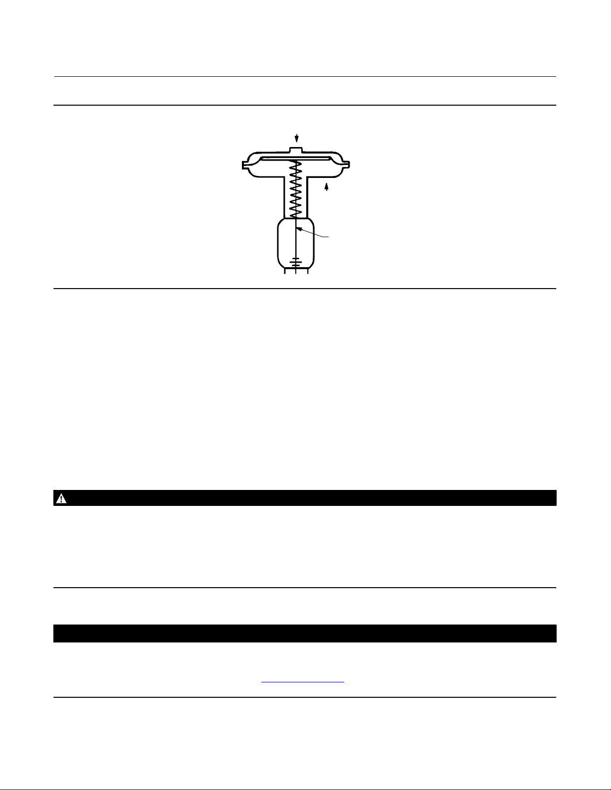
Figure 2. Schematic of Fisher 657C Actuator
AIR PUSHES
STEM DOWN
SPRING LIFTS
STEM UP
STEM
AF3833‐A
A0792‐2
Educational Services
For information on available courses for Fisher 657C diaphragm actuators, as well as a variety of other products,
contact:
Emerson Automation Solutions
Educational Services - Registration
Phone: 1-641-754-3771 or 1-800-338-8158
E-mail: education@emerson.com
emerson.com/fishervalvetraining
Installation
Key number locations are shown in figure 7 unless otherwise indicated. Also, refer to figure 3 for location of parts.
WARNING
Always wear protective gloves, clothing, and eyewear when performing any installation operations to avoid personal
injury.
Check with your process or safety engineer for any additional measures that must be taken to protect against process
media.
If installing into an existing application, also refer to the WARNING at the beginning of the Maintenance section in this
instruction manual.
CAUTION
To avoid parts damage, do not use an operating pressure that exceeds the Maximum Diaphragm Casing Pressure (table 1)
or produces a force on the actuator stem greater than the Maximum Allowable Output Thrust (table 1) or the maximum
allowable desuperheater stem load. (Contact your Emerson sales office
desuperheater stem load.)
with questions concerning maximum allowable
3
Page 4

657C Actuator (40i, 46i, and 60i)
November 2019
D Desuperheater/Actuator Assembly: If the actuator and desuperheater are shipped together as an assembly, it has
been adjusted at the factory, and may be installed in the pipeline. After installing the desuperheater in the pipeline,
refer to the Loading Connection procedures.
D Actuator Mounting: If the actuator is shipped separately or the actuator has been removed from the desuperheater,
the actuator should be mounted to the desuperheater before placing the desuperheater in the pipeline when
practical. Refer to the actuator mounting procedures before placing the desuperheater in service. You may perform
the Bench Set Spring Adjustment procedures in this section to confirm the adjustment has not changed since it was
shipped from the factory. Support actuator when in any other position than vertical.
D Positioner: If a positioner is installed, or is to be installed on the actuator, refer to the positioner instruction manual
for installation. During the adjustment procedures, it will be necessary to provide a temporary loading pressure to
the actuator diaphragm.
Instruction Manual
D104496X012
Mounting the Actuator on the Desuperheater
The 657C actuator spring loading pushes the actuator stem up towards the actuator diaphragm (see figure 2). This
spring action moves the stem away from the desuperheater while installing the actuator.
CAUTION
If the valve stem is allowed to remain in the up position (towards the actuator) during mounting, it can interfere with the
actuator mounting, possibly damage valve stem threads or bend the valve stem. Be sure the valve stem is pushed down
(into the valve body), away from the actuator while mounting.
Provide a temporary method of applying diaphragm loading pressure to the diaphragm to extend the actuator stem
during bench set spring adjustments. Provide a regulator to adjust the actuator stem during bench set spring
adjustments and a shut-off valve to isolate and prevent unwanted movement.
1. Provide a vise or some other method of supporting the desuperheater and the weight of the actuator during
assembly. Push the desuperheater stem down away from the actuator while mounting the actuator.
2. Screw the stem locknuts all the way onto the desuperheater stem. With the concave side of the travel indicator disk
(key 14, figure 7) facing the desuperheater, install the travel indicator disk on the desuperheater stem.
3. Lift or hoist the actuator onto the desuperheater yoke mounting boss:
a. Screw the yoke locknut onto the desuperheater yoke mounting boss and tighten the locknut. (Note: On small
size actuators, it may be necessary to remove the indicator disk and re‐install it while lowering the actuator on to
the desuperheater because the disk will not go through the actuator yoke opening.)
4. Do not connect the actuator stem to the desuperheater stem at this time. Whenever the actuator is installed on the
desuperheater , it is recommended to perform the Bench Set Spring Adjustment procedure to verify that the
actuator is still adjusted correctly.
4
Page 5
Instruction Manual
D104496X012
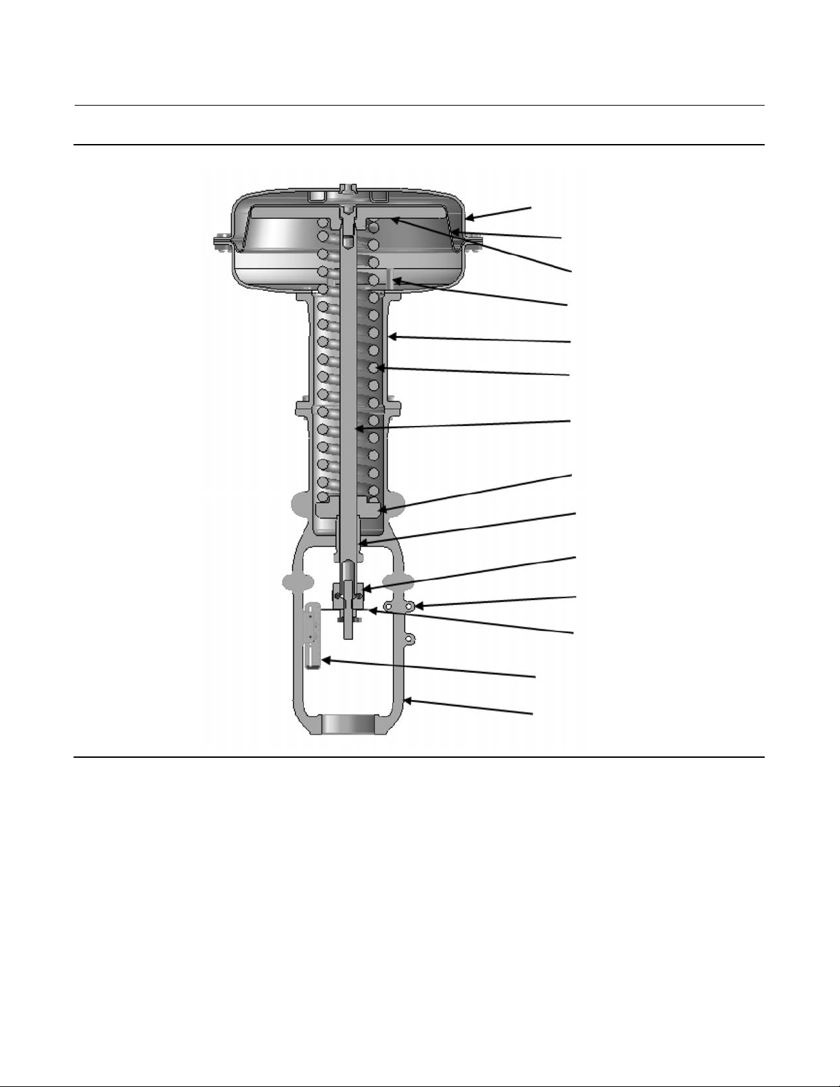
Figure 3. Actuator Components for Size 40i, 46i, and 60i Actuators
657C Actuator (40i, 46i, and 60i)
November 2019
DIAPHRAGM CASINGS
DIAPHRAGM
DIAPHRAGM PLATE
TRAVEL STOP
YOKE EXTENSION
ACTUATOR SPRING
ACTUATOR STEM
SPRING SEAT
SPRING ADJUSTOR
STEM CONNECTOR
INTEGRAL INSTRUMENT PAD
TRAVEL INDICATOR
INDICATOR SCALE
YOKE
5
Page 6
657C Actuator (40i, 46i, and 60i)
November 2019
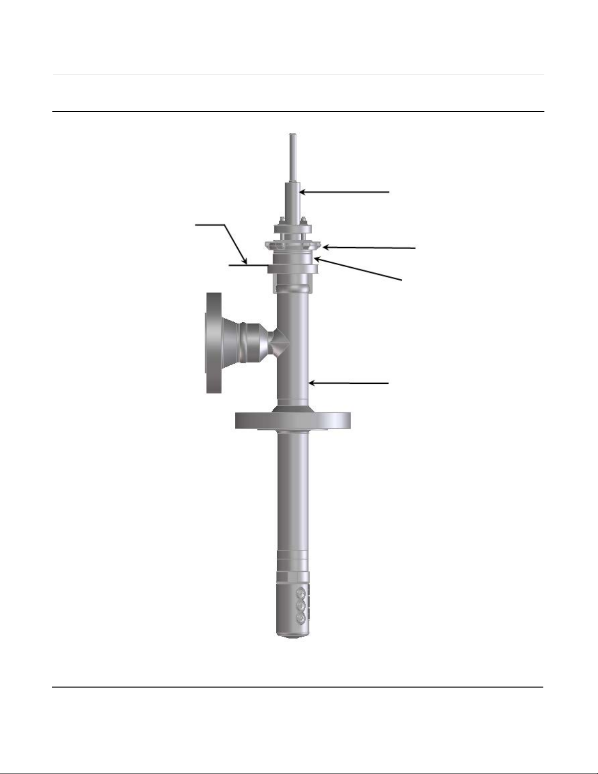
Figure 4. Construction of Yarway Desuperheater
MATCH LINE FOR
ACTUATOR
Instruction Manual
D104496X012
DESUPERHEATER STEM
YOKE LOCK NUT
YOKE BOSS DIAMETER
YARWAY DESUPERHEATER
6
Page 7
Instruction Manual
D104496X012
657C Actuator (40i, 46i, and 60i)
November 2019
Discussion of Bench Set
The bench set pressure values are used to adjust the initial compression of the actuator spring with the
desuperheater‐actuator assembly “on the bench.” The correct initial compression is important for the proper
functioning of the desuperheater‐actuator assembly when it is put into service and the proper actuator diaphragm
operating pressure is applied.
The bench set values are established with the assumption that there is no packing friction. When attempting to adjust
the spring in the field, it is very difficult to ensure that there is no friction being applied by “loose” packing.
Accurate adjustment to the bench set range can be made during the actuator mounting process by making the
adjustment before the actuator is connected to the desuperheater (see the Spring Verification procedure).
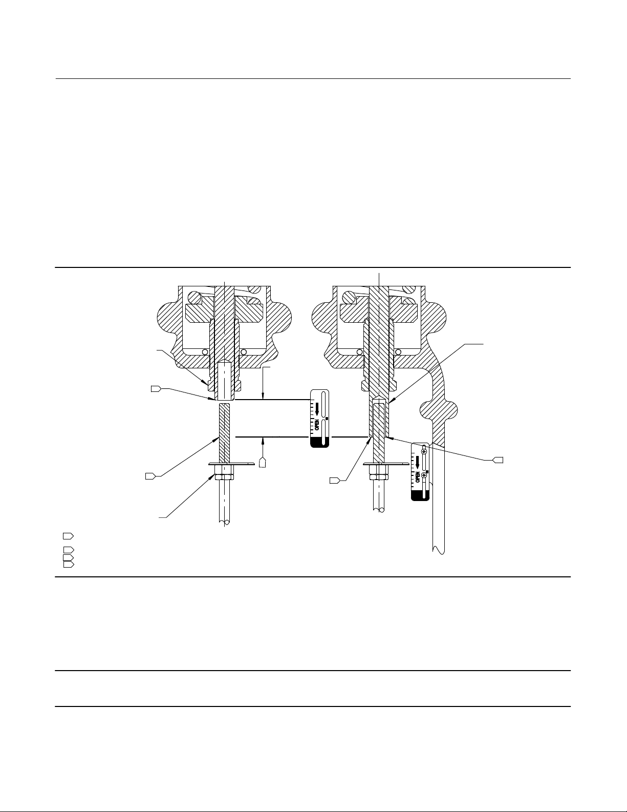
Figure 5. Bench Set Adjustment
SPRING ADJUSTER
RATED VALVE
LOWER BENCH SET
LOADING PRESSURE
UPPER BENCH SET
PRESSURE MARK
VALVE STEM
NOTES:
1
THE LOWER PSIG LOADING PRESSURE (MARKED ON NAMEPLATE) WHERE THE FIRST MOVEMENT OF
ACTUATOR STEM IS DETECTED.
2
THE UPPER PSIG LOADING PRESSURE EXTENDS ACTUATOR STEM.
3
MARK THIS POINT WITH TAPE OR A MARKER.
4
MEASURE DISTANCE OF TRAVEL. IT SHOULD EQUAL THE TRAVEL SPAN SHOWN ON THE NAMEPLATE.
1
3
TRAVEL MEASURE
4
MARK VALVE
STEM HERE
Spring Verification
ACTUATOR STEM
UPPER BENCH
SET LOADING
2
PRESSURE
3
Ensure that the actuator stem is at the top of its travel as shown in figure 5 and not connected to the desuperheater.
Note
Some spring compression is required to move the diaphragm to the top of its travel.
The steps provided are for push-down-to-open desuperheaters.
7
Page 8

657C Actuator (40i, 46i, and 60i)
November 2019
Instruction Manual
D104496X012
WARNING
When moving the actuator stem with diaphragm loading pressure, use caution to keep hands and tools out of the actuator
stem travel path. Personal injury and/or property damage is possible if something is caught between the actuator stem and
other desuperheater assembly parts.
Also, provide a certified pressure gauge suitable to accurately read the diaphragm pressure from 0 through 0.3 bar (5
psig) above the upper operating range pressure marked on the nameplate. Apply loading pressure to the diaphragm.
CAUTION
Stroke the actuator a few times to ensure that the pressure gauge is working correctly, and that the actuator is functioning
properly. To prevent actuator damage, it is important to ensure that the actuator stem is stroking smoothly and not
exhibiting binding or excessive friction. Binding or excessive friction could be an indicator of incorrect assembly or
damaged parts.
1. If not already accomplished, provide a regulator to apply an adjustable loading pressure to the actuator during
bench set adjustments and a shut-off valve to isolate and prevent the unwanted movement.
2. Set the diaphragm loading pressure at 0 bar (0 psig). Then, slowly raise the pressure towards the lower bench set
pressure, as indicated on the nameplate, while checking for the first linear movement of the actuator stem. The
actuator stem should show movement at the lower bench set pressure. If movement occurs before or after the
lower pressure is reached, adjust the spring adjuster (see figure 5) into or out of the yoke until the actuator stem's
movement is first detected at the lower bench set pressure.
3. Be sure the spring adjuster is adjusted to meet the requirements of step 2 above.
4. Apply the upper bench set pressure, as indicated on the nameplate. This pressure extends the actuator stem down
toward the desuperheater. At the end of the actuator stem, use a marker or a piece of tape to mark the
desuperheater stem (see figure 5).
Note
The actuator stem may slide over the desuperheater stem as shown in figure 5. If the actuator stem does not pass over the
desuperheater stem, provide a method to mark this point of stem travel.
5. Slowly decrease the diaphragm loading pressure to the lower bench set pressure, as indicated on the nameplate.
6. Measure the distance between the marker or tape on the desuperheater stem to the end of the actuator stem. The
distance should match the rated travel indicated on the nameplate.
7. If the measured travel matches the nameplate travel, bench set is complete. Proceed to the Installing the Stem
Connector Assembly subsection.
8. If the measured travel is not exact, consider the spring free-length and spring rate tolerances may produce a slightly
different bench set than specified. Contact your Emerson sales office
8
for assistance.
Page 9

Instruction Manual
D104496X012
657C Actuator (40i, 46i, and 60i)
November 2019
Installing the Stem Connector Assembly
When installing the stem connector assembly (key 26), the actuator and desuperheater stem threads should engage
the threads of the stem connector by the distance equal to the diameter of the stem.
WARNING
Install the stem connector securely before a positioner is mounted to the actuator and pressurized, using only a
regulator-controlled air supply, not the positioner, to move the actuator stem.
To avoid personal injury or property damage, keep hands and tools out of the actuator stem travel path while applying
loading pressure to move the actuator stem in the following steps.
CAUTION
To avoid damaging the seating surfaces, do not rotate the desuperheater plug while it is seated. Exercise care while
installing the stem connector assembly to avoid damage to the desuperheater plug stem and desuperheater stem threads.
Note
Replacement stem connectors are an assembly of two stem connector halves, cap screws, and a spacer between the connector
halves. Remove the spacer and discard, if present, before clamping the actuator and desuperheater stems together. Use only a
mated pair of stem connector halves.
1. Pull the desuperheater stem up so that it is touching the seat ring.
If necessary, screw the desuperheater stem locknuts down, away from the connector location. For all actuators,
ensure that the travel indicator disk (key 14) is located on top of the locknuts.
2. Actuator should be at lower bench set.
3. Place the stem connector half with the threaded holes, approximately half way between the actuator and
desuperheater stems, and align with the stem connector. A slight change to loading pressure may be necessary to
align the threads. Refer to figure 7 to help locate the connector position.
CAUTION
Incomplete engagement of either the desuperheater stem or actuator stem in the stem connector can result in stripped
threads or improper operation. Be sure that the length of each stem clamped in the stem connector is equal to or greater
than one diameter of that stem. Damage to threads on either stem or in the stem connector can cause the parts to be
replaced prematurely. Do not loosen the cap screws when the stem connector has spring or loading pressure force applied.
4. Install the other half of the stem connector and insert the lubricated cap screws and tighten them while ensuring
even spacing between the stem connector halves on all sides. If installing a positioner, also attach the feedback
bracket at the same time.
CAUTION
Over‐tightening the desuperheater stem locknuts can make disassembly difficult.
9
Page 10

657C Actuator (40i, 46i, and 60i)
November 2019
Instruction Manual
D104496X012
5. Screw the desuperheater stem locknuts up until the indicator disk contacts the bottom of the stem connector. Do
not overtighten the locknuts.
6. Slowly stroke the desuperheater from fully closed to fully open and verify full rated travel is achieved.
Be sure the desuperheater is in the closed position. Loosen the screws (key 17) on the travel indicator scale (key 18),
and align it with the travel indicator disk (key 14). Stroke the desuperheater full travel to ensure that the travel
matches the rated travel on the nameplate. If desuperheater travel is not correct, repeat the stem connector
procedure.
Friction Discussion
If you are attempting to adjust the bench set after the actuator is connected to the desuperheater and the packing
tightened, you must take friction into account. Make the spring adjustment so full actuator travel occurs at the bench
set values
a. Add the friction force divided by the effective diaphragm area with increasing diaphragm pressure, or,
b. Subtract the friction force divided by the effective diaphragm area with decreasing diaphragm pressure.
If the stem connector assembly has been installed, the desuperheater friction may be determined by the following
procedure:
1. Install a pressure gauge in the actuator loading pressure line that connects to the actuator diaphragm casing.
Note
Steps 2 and 4 require that you read and record the pressure shown on the pressure gauge.
2. Increase the actuator diaphragm pressure and read the diaphragm pressure as the actuator reaches a travel
position in the rated travel of the desuperheater that does not contact a travel stop. Make a reference mark on the
travel indicator scale using tape or some other method at this point.
3. Increase the actuator diaphragm pressure until the actuator is at a travel position greater than the position
referenced in step 2 using the reference point to identify first movement.
4. Decrease the actuator diaphragm pressure and read the diaphragm pressure as the actuator returns to the position
referenced in step 2.
The difference between the two diaphragm pressure readings is the change in the diaphragm pressure required to
overcome the friction forces in the two directions of travel.
5. Calculate the actual friction force:
Friction
Force, = 0.5
pounds
Difference
in pressure
readings, psig
Effective
diaphragm area,
inches
2
Refer to table 1 for the effective diaphragm area.
It is difficult to rotate the spring adjustor (key 12, figure 7) when the full actuator loading pressure is applied to the
actuator. Release the actuator loading pressure before adjusting. Then re-apply loading pressure to check the
adjustment.
Note
The actuator down stop is the limit for downward movement, and the desuperheater seat is the limit for upward (away from the
desuperheater) movement.
10
Page 11

Instruction Manual
D104496X012
657C Actuator (40i, 46i, and 60i)
November 2019
Deadband Measurement
Deadband is caused by packing friction, unbalanced forces, and other factors in the desuperheater assembly.
Deadband is the range a measured signal can vary without initiating a response from the actuator (see figure 6). Each
actuator spring has a fixed spring rate (force divided by compression). You have verified that the right spring was
installed in the actuator by completing the Spring Verification steps.
Deadband is one factor that affects the desuperheater assembly operation during automatic loop control. The control
loop tolerance for deadband varies widely depending on the loop response. Some common symptoms of the
deadband being too wide are no movement, a “jump” movement, or oscillating movements of the actuator during
automatic loop control. The following steps are provided to determine the span of deadband. The percent of
deadband is helpful in troubleshooting problems with the process control loop.
1. Start at a pressure near the lower bench set pressure, slowly increase pressure until the desuperheater is
approximately at mid‐travel. Note this pressure reading.
2. Slowly decrease pressure until movement of the desuperheater stem is detected, and note this pressure.
3. The difference between these two pressures is deadband, in psi.
4. Calculate the percent of deadband by:
Deadband, psi
Deadband = —————————————— = nn%
Bench Set Span, psi
Figure 6. Typical Desuperheater Response to Deadband
OPENING
UPPER
BENCH SET
PRESSURE
LOWER
DIAPHRAGM PRESSURE, PSIG
BENCH SET
PRESSURE
NOTE:
DEADBAND IS CAUSED BY FRICTION.
1
A6763‐2
15
BENCH SET
9
3
0
CLOSED
VALVE
MID RANGE
TRAVEL
RANGE OF
DEADBAND
CLOSING
VALVE
OPEN
1.0
0.6
1
DIAPHRAGM PRESSURE, BAR
0.2
Loading Connection
The loading pressure connections are made at the factory if the desuperheater, actuator, and positioner come as a
unit. Keep the length of tubing or piping as short as possible to avoid transmission lag in the control signal. If a volume
booster, desuperheater positioner or other accessory is used, be sure that it is properly connected to the actuator.
Refer to the positioner instruction manual or other manuals as necessary.
For actuators shipped separately or whenever the actuator pressure connections are installed, use the following steps:
11
Page 12

657C Actuator (40i, 46i, and 60i)
November 2019
Instruction Manual
D104496X012
1. Connect the loading pressure piping to the NPT internal connection in the top of the diaphragm casing.
2. If necessary, remove the 1/4 NPT bushing if a 1/2 NPT internal connection is needed to increase connection size.
The connection can be made with either piping or tubing.
3. Cycle the actuator several times to be sure that the desuperheater stem travel is correct when the correct pressure
ranges are applied to the diaphragm.
WARNING
To avoid personal injury or product damage, do not place the desuperheater into service if it is not reacting correctly to
diaphragm loading pressure changes. If desuperheater stem travel appears to be incorrect, refer to the Bench Set Spring
Adjustment procedures at the beginning of this section.
Maintenance
Actuator parts are subject to normal wear and must be inspected and replaced when necessary. The frequency of
inspection and replacement depends on the severity of service conditions.
WARNING
Avoid personal injury or property damage from sudden release of process pressure or bursting of parts. Before performing
any maintenance operations:
D Do not remove the actuator from the desuperheater while the desuperheater is still pressurized.
D Always wear protective gloves, clothing, and eyewear when performing any maintenance operations to avoid personal
injury.
D Disconnect any operating lines providing air pressure, electric power, or a control signal to the actuator. Be sure the
actuator cannot suddenly open or close the desuperheater.
D Use bypass valves or completely shut off the process to isolate the desuperheater from process pressure. Relieve
process pressure from both sides of the valve. Drain the process media from both sides of the valve.
D Vent the power actuator loading pressure and relieve any actuator spring precompression.
D Use lock‐out procedures to be sure that the above measures stay in effect while you work on the equipment.
D The desuperheater packing box may contain process fluids that are pressurized, even when the desuperheater has been
removed from the pipeline. Process fluids may spray out under pressure when removing the packing hardware or
packing rings, or when loosening the packing box pipe plug.
D Check with your process or safety engineer for any additional measures that must be taken to protect against process
media.
Actuator Maintenance
This procedure describes how the actuator can be completely disassembled and assembled. When inspection or
repairs are required, disassemble only those parts necessary to accomplish the job; then, start the assembly at the
appropriate step.
Key numbers refer to figure 7 unless otherwise indicated.
Actuator Disassembly
1. Bypass the desuperheater. Reduce the loading pressure to atmospheric, and remove the tubing or piping from the
upper diaphragm casing (key 1).
12
Page 13

Instruction Manual
(1)
D104496X012
657C Actuator (40i, 46i, and 60i)
November 2019
WARNING
To avoid personal injury from the precompressed spring force thrusting the upper diaphragm casing (key 1) away from the
actuator, relieve spring compression (step 2), and carefully remove casing cap screws (key 22, step 4).
2. Thread the spring adjuster (key 12) out of the yoke (key 9) until all spring compression is relieved.
3. If required, remove the actuator from the desuperheater body by separating the stem connector (key 26) and
removing the yoke locknut. Separate the stem connector by loosening the stem nuts (keys 15 and 16) and
unscrewing the two cap screws.
4. Remove the diaphragm casing cap screws and nuts (keys 22 and 23), then lift off the upper diaphragm casing
(key 1).
5. Remove the actuator diaphragm (key 2).
6. Remove the diaphragm plate, actuator stem, and cap screw (keys 4, 10, and 3) as an assembly. This assembly can
be broken down further, if required, by removing the cap screw (key 3).
7. Remove the actuator spring (key 6) and the spring seat (key 11).
8. If required, remove the lower diaphragm casing (key 5) from the yoke extension (key 27) by loosening the cap
screws (key 8) that hold it in place.
9. If required, remove the spring adjuster (key 12) by unscrewing it from the yoke (key 9).
10. Remove yoke extension (key 27).
Table 2. Actuator Assembly Recommended Torque Values
DESCRIPTION, KEY NUMBER ACTUATOR SIZE THREAD SIZE, INCH
Diaphragm plate to stem, key 3
Diaphragm casing, key 22 and 23
Casing to yoke, key 8 46i and 60i 3/8-16 39 29
Top-mounted handwheel and
travel stop mounting, key 141
Stem connector, key 26
Yoke extension to yoke, key 28 40i to 60i 3/8-16 39 29
1. Observe tightening pattern and procedure described in the appropriate Actuator Assembly section.
2. Torque values when lithium grease is used on the threads.
(2)
40i 1/2-20 54 40
46i and 60i 3/4-16 149 110
40i to 60i 3/8-24 27 20
40i to 60i 3/8-16 39 29
40i 5/16-18 23 17
46i and 60i 3/8-16 39 29
N•m Lbf•ft
TORQUE
Actuator Assembly
Refer to table 2 as appropriate.
1. Coat the threads and the spring seat bearing surface of the spring adjuster (key 12) with lithium grease (key 241),
and thread the spring adjuster into the yoke (key 9). Place the spring seat (key 11) in the yoke on the spring adjuster
and turn the spring adjuster to ensure that threads are properly engaged.
2. Position the yoke extension (key 27) on the yoke (key 9), and fasten the parts together by installing and evenly
tightening the cap screws (key 28).
3. Position the lower diaphragm casing (key 5) on the yoke extension (key 27), and fasten the parts together by
installing and evenly tightening the cap screws (key 8).
4. Set the actuator spring (key 6) squarely onto the spring seat (key 11).
5. If the diaphragm plate and actuator stem (keys 4 and 10) are separate, fasten them together using the cap screw
and washer (keys 3 and 25). Coat the cap screw threads with lithium grease (key 241). Tighten the cap screw (key
13
Page 14

657C Actuator (40i, 46i, and 60i)
November 2019
Instruction Manual
D104496X012
3), 54 NSm (40 lbfSft) torque for size 40i actuator, or 149 NSm (110 lbfSft) torque for size 46i and 60i actuators. Slide
the actuator stem and diaphragm plate (keys 10 and 4) into the yoke (key 9) and yoke extension (key 27) so the
actuator spring (key 6) fits squarely between the diaphragm plate and the spring seat (key 11). Then slide the
diaphragm rod through the spring adjuster (key 12).
Note
Key 25 is not part of size 40i constructions.
6. Place the diaphragm (key 2) pattern‐side up on the diaphragm plate (key 4). Align the holes in the diaphragm and
the lower diaphragm casing (key 5).
7. Position the upper diaphragm casing (key 1) on the diaphragm (key 2) and align the holes.
Note
When you replace actuator diaphragms in the field, take care to ensure the diaphragm casing bolts are tightened to the proper
load to prevent leakage, but not crush the material. Perform the following tightening sequence with a manual torque wrench.
CAUTION
Over‐tightening the diaphragm casing cap screws and nuts (keys 22 and 23) can damage the diaphragm. Do not exceed 27
NSm (20 lbfSft) torque.
Note
Do not use lubricant on these bolts and nuts. Fasteners must be clean and dry.
8. Insert the cap screws (key 22), and tighten the hex nuts (key 23) in the following manner. The first four hex nuts
tightened should be diametrically opposed and 90 degrees apart. Tighten these four hex nuts to 13 NSm (10 lbfSft).
9. Tighten the remaining hex nuts in a clockwise, criss‐cross pattern to 13 NSm (10 lbfSft).
10. Repeat this procedure by tightening four hex nuts, diametrically opposed and 90 degrees apart, to a torque of 27
NSm (20 lbfSft).
11. Tighten the remaining hex nuts in a clockwise, criss‐cross pattern to 27 NSm (20 lbfSft).
12. After the last hex nut is tightened to 27 NSm (20 lbfSft), all of the hex nuts should be tightened again to 27 NSm (20
lbfSft) in a circular pattern around the bolt circle.
13. Once completed, no more tightening is recommended.
14. Mount the actuator on the desuperheater by following the procedures in the Installation section.
Top‐Mounted Handwheel Assembly
Turning the handwheel clockwise moves the the handwheel stem (key 133, figure 7) down, compressing the spring.
Instructions are given below for complete disassembly and assembly of the top‐mounted handwheel assembly.
Perform the disassembly only as far as necessary to accomplish the required maintenance; then, begin the assembly at
the appropriate step.
Key numbers refer to figure 7 unless otherwise indicated.
14
Page 15

Instruction Manual
D104496X012
657C Actuator (40i, 46i, and 60i)
November 2019
Disassembly for Top‐Mounted Handwheel
1. Turn the handwheel (key 51) counter‐clockwise so that the handwheel assembly is not causing any spring
compression.
2. Bypass the desuperheater, reduce loading pressure to atmospheric, and remove the tubing or piping from the
upper handjack body (key 142).
WARNING
To avoid personal injury from the precompressed spring force thrusting the upper diaphragm casing (key 1) away from the
actuator, thread the spring adjuster (key 12) out of the yoke until all spring compression is relieved, then carefully remove
casing cap screws (key 22, step 4).
3. Thread the spring adjuster (key 12) out of the yoke (key 9) until all spring compression is relieved.
4. Remove the diaphragm casing cap screws and nuts (keys 22 and 23, figure 7), and lift off the upper diaphragm
casing and handwheel assembly.
5. If necessary, the handwheel assembly can be separated from the diaphragm casing by removing the cap screws
(key 141). This may be necessary to replace the O‐ring (key 139), or for ease of handling.
6. Loosen the travel stop locknut (key 137), and turn the handwheel (key 51) counter‐clockwise. Remove the cotter
pin and stop nut (keys 247 and 54), then lift off the handwheel.
7. Unscrew the travel stop locknut (key 137) from the handwheel stem (key 133), and turn the stem out of the bottom
of the body (key 142). A screwdriver slot is provided on the top of the stem for this purpose.
8. Replace the O‐ring (key 138) in the body (key 142).
9. For a handwheel assembly used on actuators, complete the disassembly by driving out the groove pin (key 140,
figure 7) and sliding the pusher plate (key 135, figure 7) off the stem.
Assembly for Top‐Mounted Handwheel
1. For a handwheel assembly used on actuators, coat the end of the handwheel stem (key 133, figure 7) with
anti‐seize lubricant (key 244). Slide the pusher plate (key 135, figure 7), onto the stem, and drive in the groove pin
(key 140, figure 7) to lock the pieces together.
2. Coat the O‐ring (key 138) with lithium grease (key 241), and insert the O‐ring in the body (key 142).
3. Coat the threads of the handwheel stem (key 133) with anti‐seize lubricant (key 244). Screw the stem into the body
(key 142).
4. Thread the travel stop locknut (key 137) onto the handwheel stem (key 133).
5. Place the handwheel (key 51), and the stop nut (key 54) on the handwheel stem (key 133). Tighten the hex nut to
fasten the parts together. Secure the nut with the cotter pin (key 247).
6. If the body (key 142) was separated from the upper diaphragm casing (key 1, figure 7), lubricate the O‐ring (key
139) with lithium grease (key 241), and place the O‐ring in the body. Align the holes in the diaphragm casing and
the body, insert the cap screws (key 141), and tighten them evenly following a crisscross pattern to ensure a proper
seal.
7. Position the upper diaphragm casing (key 1, figure 7) on the diaphragm (key 2, figure 7) and align the holes.
Note
When you replace actuator diaphragms in the field, take care to ensure the diaphragm casing bolts are tightened to the proper
load to prevent leakage, but not crush the material. Perform the following tightening sequence with a manual torque wrench.
15
Page 16

657C Actuator (40i, 46i, and 60i)
November 2019
Instruction Manual
D104496X012
CAUTION
Over‐tightening the diaphragm casing cap screws and nuts (keys 22 and 23, figure 7) can damage the diaphragm. Do not
exceed 27 NSm (20 lbfSft) torque.
Note
Do not use lubricant on these bolts and nuts. Fasteners must be clean and dry.
8. Insert the cap screws (key 22), and tighten the hex nuts (key 23) in the following manner. The first four hex nuts
tightened should be diametrically opposed and 90 degrees apart. Tighten these four hex nuts to 13 NSm (10 lbfSft).
9. Tighten the remaining hex nuts in a clockwise, criss‐cross pattern to 13 NSm (10 lbfSft).
10. Repeat this procedure by tightening four hex nuts, diametrically opposed and 90 degrees apart, to a torque of 27
NSm (20 lbfSft).
11. Tighten the remaining hex nuts in a clockwise, criss‐cross pattern to 27 NSm (20 lbfSft).
12. After the last hex nut is tightened to 27 NSm (20 lbfSft), all of the hex nuts should be tightened again to 27 NSm (20
lbfSft) in a circular pattern around the bolt circle.
13. Once completed, no more tightening is recommended.
14. Mount the actuator on the desuperheater following the procedures in the Installation section.
Casing‐Mounted Adjustable Down Travel Stops
The adjustable down travel stop (figure 8) limits the actuator stroke in the downward direction. To adjust, first relieve
actuator loading pressure before removing the travel stop cap (key 187). Then loosen the jam nut and adjust the stop
nut (keys 189 and 54) either down on the stem to limit travel, or up on the stem to allow more travel. Lock the jam nut
against the stop nut, then replace the closing cap.
Instructions are given below for disassembly and assembly. Perform the disassembly only as far as necessary to
accomplish the required maintenance; then, begin the assembly at the appropriate step.
Key numbers are shown in figure 8.
Disassembly for Casing‐Mounted Travel Stop
Bypass the desuperheater. Reduce the loading pressure to atmospheric and remove the tubing, or piping, from the
connection in the body (key 142).
Casing‐Mounted Adjustable Down Travel Stops
WARNING
To avoid personal injury from the precompressed spring force thrusting the upper diaphragm casing (key 1) away from the
actuator, relieve spring compression (step 1 and 2), and carefully remove casing cap screws (key 22, step 3).
1. Thread the spring adjuster (key 12) out of the yoke (key 9) until all spring compression is relieved.
2. Remove the travel stop cap (key 187). Unscrew the jam nut and stop nut (keys 189 and 54) until the travel stop
assembly is no longer compressing the spring. Remove the jam nut and stop nut.
16
Page 17

Instruction Manual
D104496X012
657C Actuator (40i, 46i, and 60i)
November 2019
3. Remove the upper diaphragm casing (key 1, figure 7) as outlined in the Maintenance section.
4. Remove the cap screws (keys 141) and separate the travel stop assembly from the upper casing.
5. Remove and inspect the O‐rings (key 139); replace if necessary.
6. For all actuator sizes: Loosen the stop nut (key 54), then unscrew the travel stop stem (key 133) out of the actuator
stem. The lower diaphragm plate can now be removed.
Assembly for Casing‐Mounted Travel Stop
1. Reassemble the up or down travel stop in the reverse order of the disassembly steps, being sure to apply lithium
grease as shown by the lubrication boxes (key 241) in figures 7 or 9 as appropriate.
2. Readjust the travel stop to obtain the appropriate restriction by following the adjustment procedures presented in
the introductory portion of the Casing‐Mounted Adjustable Travel Stops section. Return the unit to operation.
17
Page 18

657C Actuator (40i, 46i, and 60i)
November 2019
Instruction Manual
D104496X012
Parts Ordering
Each actuator has a serial number stamped on the nameplate. Always mention this number when corresponding with
your Emerson sales office
regarding technical information or replacement parts.
WARNING
Use only genuine Fisher replacement parts. Components that are not supplied by Emerson Automation Solutions should
not, under any circumstances, be used in any Fisher actuator, because they may void your warranty, might adversely affect
the performance of the actuator, and could cause personal injury and property damage.
Parts Kits
Kits for Top‐Mounted Handwheels
Retrofit kit includes parts to add a top-mounted handwheel. Kit 1 includes the handwheel assembly only. Kit 2 includes Kit 1 and a new diaphragm case that is
required to mount the handwheel assembly.
Kit 1
Description
Size 40i
Sizes 46i and 60i
Kit 2
Description
Size 40i
Sizes 46i and 60i
Thread Size Part Number
1/4 NPT 38A1209X032
1/2 NPT CF
1/4 NPT 32B0262X012
1/2 NPT CF
Thread Size Part Number
1/4 NPT 38A1209X042
1/2 NPT CF
1/4 NPT 32B0262X022
1/2 NPT CF
Kits for Adjustable Down Travel Stops
Retrofit kit includes parts to add an adjustable down travel stop. Kit 1includes the adjustable down travel stop assembly only. Kit 2 includes Kit1 and a new
diaphragm case that is required to mount the adjustable down travel stop assembly.
Kit 1
Description
Size 40i
Sizes 46i and 60i
Kit 2
Description
Size 40i
Sizes 46i and 60i
Thread Size Part Number
1/4 NPT BV8054X0042
1/2 NPT BV8054X0052
1/4 NPT BV8054X0062
1/2 NPT CF
Thread Size Part Number
1/4 NPT BV8054X0012
1/2 NPT BV8054X0022
1/4 NPT BV8054X0032
1/2 NPT CF
18
Page 19

Instruction Manual
D104496X012
657C Actuator (40i, 46i, and 60i)
November 2019
Parts List
Note
Contact your Emerson sales office
Actuator Assembly
(figure 7)
Key Description
1 Upper Diaphragm Casing
2* Diaphragm
3 Cap Screw
4 Diaphragm Plate
5 Lower Diaphragm Casing
6 Actuator Spring
7 Travel Stop Cap Screw
8 Cap Screw
9 Yoke
10 Actuator Stem
11 Spring Seat
12 Spring Adjuster
13 Lower Diaphragm Plate
14 Travel Indicator Disk
15 Stem Nut
16 Stem Jam Nut
17 Self‐Tapping Screw
18 Travel Indicator Scale
19 Nameplate
20 Drive Screw
22 Cap Screw
23 Hex Nut
24 Twin Speed Nut
(1)
25
Washer
26 Stem Connector Assy
28 Screw
27 Yoke Extension
30 Indicator Adaptor
31 Machine Screw
32 Washer
33 Pipe Bushing
241 Lubricant, Lithium Grease (not furnished with the actuator)
249 Warning Nameplate
for part numbers.
Top Mounted Handwheel
(figure 7)
Key Description
51 Handwheel
54 Stop Nut
133 Handwheel Stem
135 Pusher Plate
137 Casing‐Mounted Travel Stop Locknut
138* O‐Ring
139* O‐Ring
140 Groove Pin
141 Cap Screw
142 Body
164 Body Extension
(2)
171
Thrust Bearing
241 Lubricant, Lithium Grease (not furnished with actuator)
244 Lubricant, Anti‐Seize (not furnished with handwheel)
(2)
246
Spacer
247 Cotter Pin
1. Key 25 not part of size 40i constructions
2. Key 171 and 246 not part of size 40i constructions.
*Recommended spare parts
19
Page 20

657C Actuator (40i, 46i, and 60i)
November 2019
Figure 7. Fisher 657C Actuator Sizes 40i through 60i
Instruction Manual
D104496X012
APPL Y LUB
PARTS NOT SHOWN: KEY 7, 24, AND 249
NOTE:
KEY 25 IS NOT PART OF SIZE 40i CONSTRUCTIONS.
1
20
Page 21

Instruction Manual
D104496X012
Figure 8. Top-Mounted Handwheel Assembly for Size 40i through 60i Actuators
1
657C Actuator (40i, 46i, and 60i)
November 2019
1
32B0262_B
APPL Y LUB
NOTE:
KEY 171 AND 246 ARE NOT PART OF SIZE 40I CONSTRUCTIONS.
1
21
Page 22

657C Actuator (40i, 46i, and 60i)
November 2019
Figure 9. Casing-Mounted Adjustable Down Travel Stop for Size 40i and 60i Actuators
Instruction Manual
D104496X012
APPL Y LUB
Casing-Mounted Adjustable
Down Travel Stop (figure 8)
Key Description
54 Stop Nut
133 Travel Stop Stem
134 Washer
139* O-RIng
141 Cap Screw
142 Body
187 Travel Stop Cap
189 Jam Nut
241 Lubricant, Lithium Grease (not furnished with actuator)
22
*Recommended spare parts
Page 23

Instruction Manual
D104496X012
657C Actuator (40i, 46i, and 60i)
November 2019
23
Page 24

657C Actuator (40i, 46i, and 60i)
November 2019
Instruction Manual
D104496X012
Neither Emerson, Emerson Automation Solutions, nor any of their affiliated entities assumes responsibility for the selection, use or maintenance
of any product. Responsibility for proper selection, use, and maintenance of any product remains solely with the purchaser and end user.
Fisher, Templow, and Yarway are marks owned by one of the companies in the Emerson Automation Solutions business unit of Emerson Electric Co.
Emerson Automation Solutions, Emerson, and the Emerson logo are trademarks and service marks of Emerson Electric Co. All other marks are the property
of their respective owners.
The contents of this publication are presented for informational purposes only, and while every effort has been made to ensure their accuracy, they are not
to be construed as warranties or guarantees, express or implied, regarding the products or services described herein or their use or applicability. All sales are
governed by our terms and conditions, which are available upon request. We reserve the right to modify or improve the designs or specifications of such
products at any time without notice.
Emerson Automation Solutions
Marshalltown, Iowa 50158 USA
Sorocaba, 18087 Brazil
Cernay, 68700 France
Dubai, United Arab Emirates
Singapore 128461 Singapore
www.Fisher.com
24
E 2019 Fisher Controls International LLC. All rights reserved.
 Loading...