

Page 1

Instruction Manual
D102087X012
Fisher™ 585C Series Piston Actuators
585C Actuator
March 2021
Contents
Introduction 1.................................
Scope of Manual 1.............................
Description 2.................................
Specifications 2...............................
Educational Services 2.........................
Principle of Operation 8.........................
Actuator with Handwheel 8.....................
Actuator with Spring Return 10..................
Installation 10.................................
Bypass Assembly 11...........................
Three‐Way Valve Applications Note 11............
Actuator Mounting 11...........................
Size 25 and 50 Actuator Mounting 11.............
Size 60‐130 Actuator Mounting 13...............
Stem Connector Assembly (Size 60‐130) 13....
585C Handwheels 14...........................
Handwheel Operation (Sizes 25 and 50) 14........
Handwheel Operation (Sizes 60‐130) 14..........
Maintenance (Sizes 25 and 50) 15.................
Replacing Handwheel Housing O‐Ring or
Thrust Bearings (Sizes 25 and 50) 16...........
Replacing Seals, Changing Action, or
Changing Bias Spring(s) (Sizes 25 and 50) 17....
Maintenance (Sizes 60‐130) 20...................
Side‐Mounted Handwheel Maintenance
(Sizes 60‐130) 21...........................
Disassembly of Handwheel Constructions
(Sizes 60 and 68) 21.....................
Figure 1. Fisher 585C Series Piston Actuator
X0175-2
Disassembly of Handwheel Constructions
(Sizes 80‐130) 22........................
Reassembly (Sizes 60‐130) 22...............
Parts Ordering 22...............................
Parts Kits 23...................................
Parts List 24...................................
Sizes 25 and 50 24.............................
Sizes 60‐130 30...............................
Introduction
Scope of Manual
This instruction manual provides information on installation, maintenance, and parts ordering for the Fisher 585C
piston actuators. Refer to separate instruction manuals for information about other equipment and accessories used
with these actuators.
Information for the 585CLS long stroke actuator can be found in the Fisher 585CLS Instruction Manual
(D103793X012
www.Fisher.com
).
Do not install, operate, or maintain a 585C Series actuator without being fully trained and qualified in
valve, actuator, and accessory installation, operation, and maintenance. To avoid personal injury or
property damage, it is important to carefully read, understand, and follow all the contents of this
manual, including all safety cautions and warnings. If you have any questions about these instructions,
contact your Emerson sales office
before proceeding.
Page 2

585C Actuator
March 2021
Instruction Manual
D102087X012
Description
585C pneumatic piston actuators (figure 1) provide accurate throttling or on‐off control of sliding‐stem valves. The
585C actuator uses a double‐acting cylinder, which requires air pressure for operation.
Size 25 and 50 actuators are available as a springless construction or with a bias spring. Depending on configuration,
the bias spring will retract or extend the piston rod upon loss of cylinder air pressure. Size 60 through 130 actuators are
available as springless constructions only.
585C actuators are typically supplied with a DVC6200 digital valve controller, or a 3600 P/P or I/P analog positioner.
The 585C actuator is available with a top‐mounted or side‐mounted manual handwheel, depending on actuator size.
Specifications
Specifications for the 585C piston actuators are given in table 1. Some individual actuators come from the factory with
specifications stamped on a nameplate attached to the yoke.
Educational Services
For information on available courses for Fisher 585C Series piston actuators, as well as a variety of other products,
contact:
Emerson Automation Solutions
Educational Services - Registration
Phone: 1-641-754-3771 or 1-800-338-8158
E-mail: education@emerson.com
emerson.com/fishervalvetraining
2
Page 3

Instruction Manual
D102087X012
Table 1. 585C Specifications (Sizes 25‐130)
585C Actuator
March 2021
Operating Pressure
(1)
Sizes 25‐50
Maximum Allowable: 10.3 bar (150 psig)
Minimum Recommended: 1.4 bar (20 psig)
Sizes 60‐130
Maximum Allowable: See table 8
Minimum Recommended: 2.4 bar (35 psig)
Travel
See table 2
Thrust Capabilities
See tables 4 through 8
Stroking Speeds
Varies with actuator size, actuator spring, travel, and
supply pressure. If stroking speed is critical, consult
your Emerson sales office
Piston Area
See table 2
Construction Materials
Part Material
Yoke Ductile Iron
Piston Aluminum
Cylinder Aluminum
Bolting and Fasteners
Springs
(sizes 25 and 50 only)
O‐Rings
Actuator Stem Chrome‐plated Steel
Stem Connection Stainless Steel
Travel Indicator Scale Stainless Steel
Paint Polyester Powder
Cylinder Seal Bushings
(sizes 60‐130 only)
Stem Connector
(sizes 60‐130)
Approximate Weights
(less positioner and handwheel)
Size 25
Cylinder Volumetric Displacement
See table 2
2‐1/8 inch yoke boss, 7 kg (16 pounds)
2‐13/16 inch yoke boss, 8 kg (17 pounds)
Size 50
Operative Temperature Limits
(1)
For All Sizes
Standard Construction
(Nitrile O‐Rings): -40 to 80_C (-40 to 175_F)
Optional Construction
(Fluorocarbon O‐Rings): -18 to 149_C (0 to 300_F)
For Sizes 60-130
2‐13/16 inch yoke boss, 20 kg (45 pounds)
3‐9/16 inch yoke boss, 22 kg (48 pounds)
Size 60: 31 kg (68 pounds)
Size 68: 54 kg (120 pounds)
Size 80: 102 kg (225 pounds)
Size 100: 113 kg (250 pounds)
Size 130: 188 kg (415 pounds)
Low Ambient Temperature option:
Fluorosilicone O-Rings: -60 to 80_C (-76 to 175_F)
Options
Sizes 25 and 50
Yoke Boss and Valve Stem Diameters
See table 3
J Top‐mounted handwheel, see figures 5, 7, and 8
and table 9
J Cylinder bypass valve J Limit switches J Fisher
Pressure Connections
Size 25‐60
J 1/4 NPT internal (standard), or J 3/8 NPT internal
(optional)
Sizes 68‐130
J 1/2 NPT internal (standard)
Instrument Mounting
Universal NAMUR mounting
1. The pressure/temperature limits in this manual and any applicable standard or code limitation for valve should not be exceeded.
4200 position transmitter
Sizes 60‐130
J Integral side‐mounted handwheel, (figure 9)
Sizes 25‐130
J FIELDVUEt mounting options
J Fisher 377 trip valve system to fail actuator
J up or J down or J lock in last position
J TopWorxt DXP M21GNEB electrical valve stem
position switch
J Micro‐Switch limit switches
Steel NCF (std)
Stainless Steel (std and low ambient)
Alloy Steel
Nitrile (std), Fluorocarbon,
Fluorosilicone
Brass
Zinc‐plated steel (std)
Stainless Steel (std and low ambient)
3
Page 4

585C Actuator
Instruction Manual
March 2021
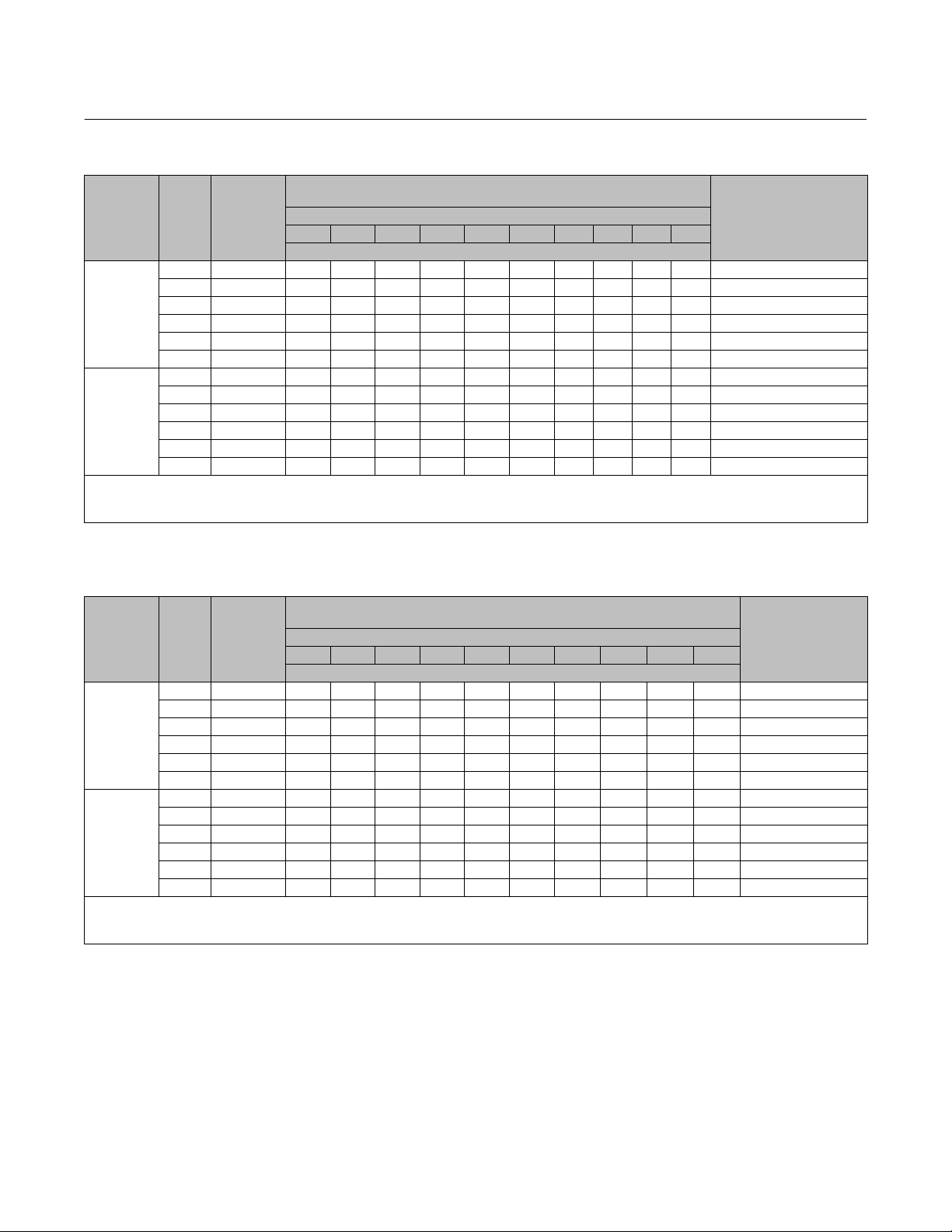
Table 2. Fisher 585C Piston Cylinder Clearance Volumes
PISTON AT TOP OF CYLINDER (SPRINGS BELOW PISTON FOR SIZE 25 AND 50)
Actuator
Size
25 168 26 2.9 1.125 104 6.3 1750 107
50 303 47 5.1 2 330 20 5200 320
60 358 55.5
68 571 88.5
80 571 88.5
100 842 130.5
130 1430 221.5
Actuator
Size
25 168 26 2.9 1.125 77 4.7 1790 109
50 303 47 5.1 2 350 22 5200 320
Piston Area Maximum Actuator Travel Upper Clearance Volume Volume Below Piston
cm
2
Inches
2
cm Inches cm
3
Inches
3
cm
3
5.1 2 310 19 2700 163
10 4 310 19 4400 270
20 8 310 19 8200 500
5.1 2 1230 75 7500 460
10.2 4 1230 75 7500 460
20.3 8 1230 75 13300 810
10.2 4 1230 75 7500 460
20.3 8 1230 75 13300 810
10.2 4 1700 104 10700 650
20.3 8 1700 104 19200 1170
10.2 4 4600 280 18500 1130
20.3 8 4600 280 33000 2000
PISTON AT BOTTOM OF CYLINDER (SPRINGS ABOVE PISTON FOR SIZE 25 AND 50)
Piston Area Maximum Actuator Travel Lower Clearance Volume Volume Above Piston
cm
2
Inches
2
cm Inches cm
3
Inches
3
cm
3
D102087X012
3
Inches
3
Inches
Table 3. Yoke Boss and Valve Stem Diameters
ACTUATOR SIZE
25
50
60 90 3‐9/16 19.1 3/4
68 90 3‐9/16 19.1 3/4
80 127 5, 5H
100 127 5, 5H
130 127 5, 5H
1. Heavy actuator to bonnet bolting.
YOKE BOSS DIAMETER VALVE STEM DIAMETER
mm Inches mm Inches
54
71
71
90
2‐1/8
2‐13/16
2‐13/16
3‐9/16
9.5
12.7
12.7
19.1
25.4
31.8
25.4
31.8
25.4
31.8
3/8
1/2
1/2
3/4
1
1‐1/4
1
1‐1/4
1
1‐1/4
4
Page 5

Instruction Manual
585C Actuator
D102087X012
Actuator Thrust Capabilities
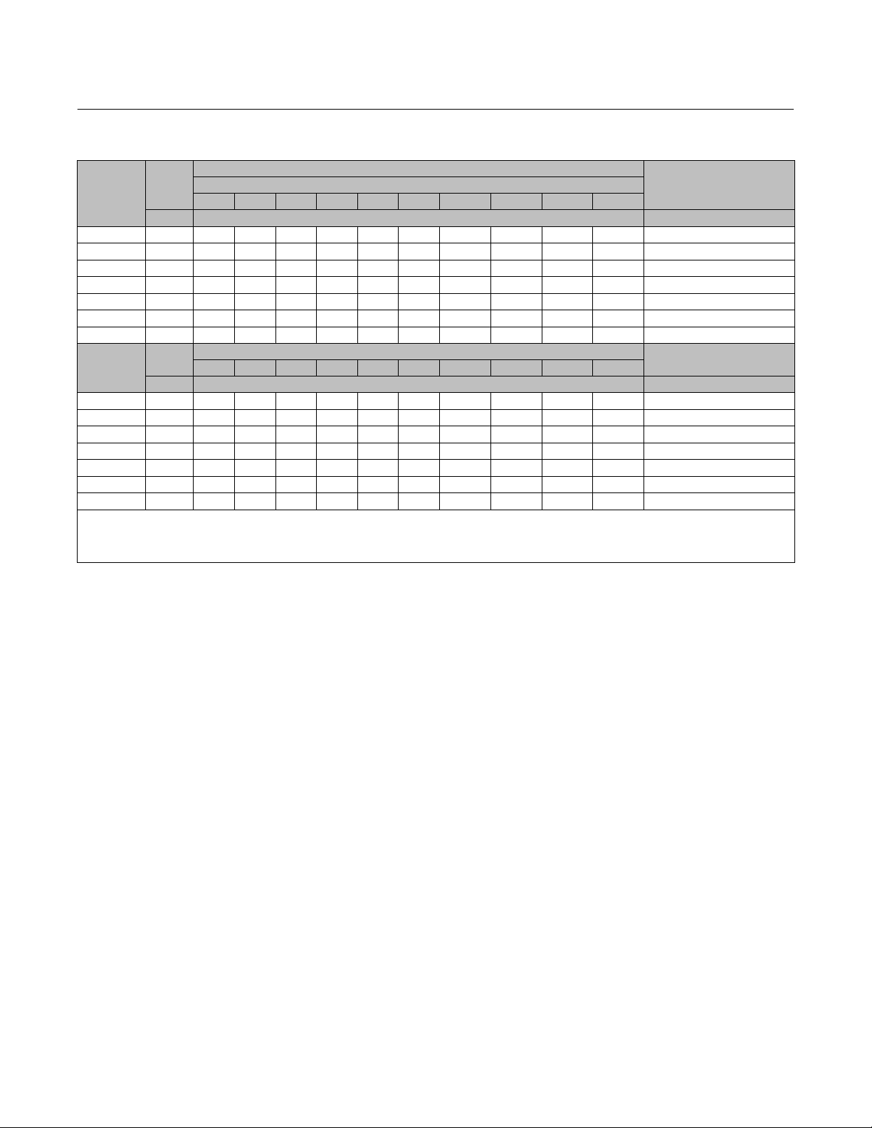
Table 4. Fisher 585C Size 25 and 50 Actuator Thrust Capabilities, U.S. Units (spring retracts actuator stem)
ACTU‐
ATOR
SIZE
25
50
X—Indicates where the listed supply pressure is not sufficient to overcome the opposing bias spring effect.
ACTUATOR
SPRING
RATE,
lb/in
200
400
500
700
900
330
600
930
1550
1880
STEM
TRAVEL,
INCHES
0 All 0 0 1040 1300 1560 1820 2080 2340 2600 2860 3250 3900
0.5625
0.75
0.875
1.125
0.5625
0.75
0.875
1.125
0.5625
0.75
0.875
1.125
0.5625
0.75
0.875
1.125
0.5625
0.75
0.875
1.125
0 All 0 0 1840 2300 2760 3220 3680 4140 4600 5060 5750 6900
0.75
0.875
1.125
1.5
2
0.75
0.875
1.125
1.5
2
0.75
0.875
1.125
1.5
2
0.75
0.875
1.125
1.5
2
0.75
0.875
1.125
1.5
2
SPRING
THRUST W/
ACTUATOR
STEM
RETRACTED,
POUNDS
200
200
200
200
400
400
400
400
500
500
500
500
700
700
700
700
900
900
900
900
330
330
330
330
330
600
600
600
600
600
930
930
930
930
930
1550
1550
1550
1550
1550
1880
1880
1880
1880
1880
SPRING
THRUST W/
ACTUATOR
STEM
EXTENDED,
POUNDS
313
350
375
425
625
700
750
850
781
875
938
1063
1094
1225
1313
1488
1406
1575
1688
1913
578
619
701
825
990
1050
1125
1275
1500
1800
1628
1744
1976
2325
2790
2710
2906
3294
3875
4650
3290
3525
3995
4700
5640
NET THRUST FOR 585C WITH ACTUATOR STEM FULLY
40 50 60 70 80 90 100 110 125 150
730
990
690
950
660
920
610
870
410
670
340
600
290
550
190
450
520
260
420
160
360
100
240
X
X
200
X
70
X
X
X
X
X
X
X
X
X
X
X
X
1310
1780
1270
1740
1180
1660
1060
1530
900
1370
840
1310
760
1230
610
1080
390
860
90
560
260
730
140
610
X
380
X
30
X
X
X
X
X
X
X
X
X
X
X
X
X
X
X
X
X
X
X
X
X
X
EXTENDED AT FULL TRAVEL
Operating Pressure, psig
Force, Pounds
1250
1510
1210
1470
1180
1440
1130
1390
930
1190
860
1120
810
1070
710
970
780
1040
680
940
620
880
500
760
460
720
330
590
250
510
70
330
150
410
X
240
X
130
X
X
2250
2720
2210
2680
2130
2600
2000
2470
1840
2310
1780
2250
1700
2170
1550
2020
1330
1800
1030
1500
1200
1670
1080
1560
850
1320
500
970
40
510
110
580
X
385
X
X
X
X
X
X
X
X
X
X
X
X
X
X
X
X
1760
1730
1700
1650
1450
1380
1330
1230
1300
1200
1140
1010
980
850
760
590
670
500
390
160
3190
3150
3070
2950
2780
2720
2650
2500
2270
1970
2140
2030
1790
1450
980
1050
855
465
X
X
470
235
X
X
X
2020
1990
1960
1910
1710
1640
1590
1490
1560
1460
1400
1270
1240
1110
1020
850
930
760
650
420
3660
3620
3540
3420
3250
3190
3120
2970
2740
2440
2610
2500
2270
1920
1450
1520
1325
935
355
X
940
705
235
X
X
2280
2250
2220
2170
1970
1900
1850
1750
1820
1720
1660
1530
1500
1370
1280
1110
1190
1020
910
680
4140
4090
4010
3890
3720
3660
3590
3440
3210
2910
3090
2970
2740
2390
1920
1990
1795
1405
825
50
1410
1175
705
X
X
2540
2510
2480
2430
2230
2160
2110
2010
2080
1980
1920
1790
1760
1630
1540
1370
1450
1280
1170
940
4610
4570
4480
4360
4190
4130
4060
3910
3680
3380
3560
3440
3210
2860
2390
2460
2265
1875
1295
520
1880
1645
1175
470
X
2930
2900
2870
2820
2620
2550
2500
2400
2460
2370
2310
2180
2150
2020
1930
1760
1840
1670
1560
1330
5310
5270
5190
5070
4900
4840
4770
4620
4390
4090
4260
4150
3910
3570
3100
3165
2970
2580
2000
1225
2585
2350
1880
1175
235
3580
3550
3520
3470
3270
3200
3150
3050
3110
3020
2960
2830
2800
2670
2580
2410
2490
2320
2210
1980
6490
6450
6370
6250
6080
6020
5950
5800
5570
5270
5440
5330
5090
4750
4280
4345
4150
3760
3180
2405
3765
3530
3060
2355
1415
March 2021
SPRINGS
USED,
BY
COLOR
Springs
Not Used
Gold
Light
Green
White
Gold &
White
Light
Green
& White
Springs
Not Used
Pink
Light
Blue
Pink &
Light
Blue
Green
Pink &
Green
5
Page 6

585C Actuator
March 2021
Instruction Manual
D102087X012
Table 5. Fisher 585C Size 25 and 50 Actuator Thrust Capabilities, Metric Units (spring retracts actuator stem)
ACTU‐
ATOR
SIZE
SPRING
RATE,
N/mm
ATOR
STEM
TRAVEL,
mm
0 All 0 0 4626 5783 6939 8096 9252 10,409 11,565 12,722 14,457 17,348
14.3
19.1
35.0
22.2
28.6
14.3
19.1
70.1
22.2
28.6
ACTU‐
25
122.6
157.7
105.1
50
162.9
271.4
329.2
X—Indicates where the listed supply pressure is not sufficient to overcome the opposing bias spring effect.
14.3
19.1
87.6
22.2
28.6
14.3
19.1
22.2
28.6
14.3
19.1
22.2
28.6
0 All 0 0 8180 10,200 12,300 14,300 16,400 18,400 20,500 22,500 25,600 30,700
19.1
22.2
28.6
57.8
38.1
50.8
19.1
22.2
28.6
38.1
50.8
19.1
22.2
28.6
38.1
50.8
19.1
22.2
28.6
38.1
50.8
19.1
22.2
28.6
38.1
50.8
SPRING
THRUST W/
ACTUATOR
STEM
RETRACTED,
N
890
890
890
890
1780
1780
1780
1780
2225
2225
2225
2225
3115
3115
3115
3115
4005
4005
4005
4005
1468
1468
1468
1468
1468
2669
2669
2669
2669
2669
4137
4137
4137
4137
4137
6894
6894
6894
6894
6894
8362
8362
8362
8362
8362
SPRING
THRUST W/
ACTUATOR
STEM
EXTENDED,
N
1393
1558
1669
1891
2781
3115
3338
3783
3475
3894
4174
4730
4868
5451
5843
6622
6257
7009
7512
8513
2571
2753
3118
3670
4404
4671
5004
5671
6672
8007
7242
7758
8790
10,342
12,410
12054
12925
14652
17236
20683
14634
15679
17770
20906
25087
NET THRUST FOR 585C WITH ACTUATOR STEM FULLY
EXTENDED AT FULL TRAVEL
Operating Pressure, bar
2.8 3.4 4.1 4.8 5.5 6.2 6.9 7.6 8.6 10.3
Force, N
3247
4404
5560
6717
7829
8985
10,142
3069
2936
2713
1824
1512
1290
845
1156
712
445
X
X
X
X
X
X
X
X
X
5827
5649
5249
4715
4003
3736
3381
2713
1735
400
1157
623
X
X
X
X
X
X
X
X
X
X
X
X
X
4226
4092
3870
2980
2669
2447
2002
2313
1868
1601
1068
890
311
X
X
X
X
X
X
7918
7740
7384
6806
6094
5827
5471
4804
3825
2491
3247
2713
1690
133
X
X
X
X
X
X
X
X
X
X
X
5382
5249
5026
4137
3825
3603
3158
3470
3025
2758
2224
2046
1468
1112
311
667
X
X
X
10,008
9831
9475
8896
8185
7918
7562
6895
5916
4582
5338
4804
3781
2224
178
489
X
X
X
X
X
X
X
X
X
6539
6405
6183
5293
4982
4760
4315
4626
4181
3914
3381
3203
2624
2269
1468
1824
1068
578
X
12,099
11,921
11,565
10,987
10,275
10,008
9653
8985
8007
6672
7428
6939
5872
4315
2269
2580
1712
X
X
X
X
X
X
X
X
7695
7562
7340
6450
6139
5916
5471
5783
5338
5071
4493
4359
3781
3381
2624
2980
2224
1735
712
14,190
14,012
13,656
13,122
12,366
12,099
11,788
11,121
10,097
8763
9519
9030
7962
6450
4359
4670
3803
2068
X
X
2091
1045
X
X
X
8852
8718
8496
7606
7295
7073
6628
6939
6494
6227
5649
5516
4938
4537
3781
4137
3381
2891
1868
16,280
16,102
15,747
15,213
14,457
14,190
13,878
13,211
12,188
10,854
11,610
11,121
10,097
8541
6450
6761
5894
4159
1579
X
4181
3136
1045
X
X
10,008
9875
9653
8763
8452
8229
7784
8096
7651
7384
6806
6672
6094
5694
4938
5293
4537
4048
3025
18,416
18,193
17,837
17,303
16,547
16,280
15,969
15,302
14,279
12,944
13,745
13,211
12,188
10,631
8541
8852
7984
6249
3670
222
6272
5226
3136
X
X
11,298
11,165
11,032
10,809
20,506
20,328
19,928
19,394
18,638
18,371
18,060
17,392
16,369
15,035
15,836
15,302
14,279
12,722
10,631
10942
10075
9919
9608
9386
8941
9252
8807
8541
7962
7829
7251
6850
6094
6450
5694
5204
4181
8340
5760
2313
8362
7317
5226
2091
X
13,033
12,900
12,766
12,544
11,654
11,343
11,121
10,676
10,943
10,542
10,275
9697
9564
8985
8585
7829
8185
7428
6939
5916
23,620
23,442
23,086
22,552
21,796
21,529
21,218
20,551
19,528
18,193
18,949
18,460
17,392
15,880
13,789
14078
13211
11476
8896
5449
11498
10453
8362
5226
1045
15,925
15,791
15,658
15,435
14,546
14,234
14,012
13,567
13,834
13,434
13,167
12,588
12,455
11,877
11,476
10,720
11,076
10,320
9831
8807
28,869
28,691
28,335
27,801
27,045
26,778
26,467
25,800
24,777
23,442
24,198
23,709
22,641
21,129
19,038
19,328
18,460
16,725
14,145
10,698
16,748
15,702
13,612
10,476
6294
SPRINGS
USED,
BY
COLOR
Springs
Not
Used
Gold
Light
Green
White
Gold &
White
Light
Green &
White
Springs
Not
Used
Pink
Light
Blue
Pink &
Light
Blue
Green
Pink &
Green
6
Page 7
Instruction Manual
585C Actuator
D102087X012
Table 6. Fisher 585CR Size 25 and 50 Actuator Thrust Capabilities, U.S. Units (spring extends actuator stem)
SPRING
lb/in
THRUST W/
ACTUATOR
STEM
EXTENDED,
40 50 60 70 80 90 100 110 125 150
ACTUATOR
SIZE
SPRING
RATE,
POUNDS
0 0 1040 1300 1560 1820 2080 2340 2600 2860 3250 3900 Springs Not Used
200 200 1240 1500 1760 2020 2280 2540 2800 3060 3450 X Gold
25
(2)
400 400 1440 1700 1960 2220 2480 2740 3000 3260 3650 X Light Green
500 500 1540 1800 2060 2320 2580 2840 3100 3360 3750 X White
700 700 1740 2000 2260 2520 2780 3040 3300 3560 X X Gold & White
900 900 1940 2200 2460 2720 2980 3240 3500 3760 X X Light Green & White
0 0 1840 2300 2760 3220 3680 4140 4600 5060 5750 6900 Springs Not Used
330 330 2210 2680 3150 3620 4090 4560 5030 5500 6205 X Pink
50
(3)
600 600 2480 2950 3420 3890 4360 4830 5300 5770 6475 X Light Blue
930 930 2810 3280 3750 4220 4690 5160 5630 6100 6805 X Pink & Light Blue
1550 1550 3430 3900 4370 4840 5310 5780 6250 6720 X X Green
1880 1880 3760 4230 4700 5170 5640 6110 6580 7050 X X Pink & Green
X—Indicates where the listed supply pressure is not sufficient to overcome the opposing bias spring effect.
1. The maximum design pressure for size 25 and 50 actuator is 150 psig.
2. Maximum thrust is 3900 lbs.
3. Maximum thrust is 6900 lbs.
TOTAL THRUST FOR 585CR WITH ACTUATOR STEM FULLY
EXTENDED
Operating Pressure, psig
(1)
Force, Pounds
SPRINGS USED, BY COLOR
March 2021
Table 7. Fisher 585CR Size 25 and 50 Actuator Thrust Capabilities, Metric Units (spring extends actuator stem)
SPRING
ACTUATOR
SIZE
SPRING
RATE,
N/mm
THRUST W/
ACTUATOR
STEM
EXTENDED,
2.8 3.4 4.1 4.8 5.5 6.2 6.9 7.6 8.6 10.3
N
0 0 4626 5782 6939 8095 9251 10408 11565 12721 14456 17347 Springs Not Used
35.0 890 5516 6672 7828 8985 10141 11298 12454 13610 15346 X Gold
25
(2)
70.0 1780 6405 7562 8718 9874 11031 12188 13344 14500 16235 X Light Green
87.6 2225 6850 8006 9163 10319 11476 12632 13789 14945 16680 X White
122.6 3115 7740 8896 10052 11209 12365 13655 14678 15835 X X Gold & White
157.6 4005 8629 9786 10942 12099 13255 14412 15568 16724 X X Light Green & White
0 0 8180 10200 12300 14300 16400 18400 20500 22500 25600 30700 Springs Not Used
57.8 1468 9830 11921 14011 16102 18192 20282 22373 24464 27600 X Pink
50
(3)
105.1 2670 11031 13122 15212 17303 19393 21484 23574 25665 28800 X Light Blue
162.8 4135 12499 14589 16680 18770 20861 22952 25042 27133 30269 X Pink & Light Blue
271.4 6894 15256 17347 19438 21528 23619 25709 27800 29891 X X Green
329.2 8362 16724 18815 20906 22996 25087 27177 29268 31358 X X Pink & Green
X—Indicates where the listed supply pressure is not sufficient to overcome the opposing bias spring effect.
1. The maximum design pressure for size 25 and 50 actuator is 10.3 bar.
2. Maximum thrust is 17347 N.
3. Maximum thrust is 31358 N.
TOTAL THRUST FOR 585CR WITH ACTUATOR STEM FULLY
EXTENDED
Operating Pressure, bar
(1)
Force, N
SPRINGS USED, BY
COLOR
7
Page 8
585C Actuator
March 2021
Instruction Manual
D102087X012
Table 8. Fisher 585C Thrust (springless construction)
ACTUATOR
SIZE
25 168 4630 5780 6940 8100 9260 10400 11600 12700 14500 17300 17300
50 303 8180 10200 12300 14300 16400 18400 20500 22500 25600 30700 31400
60 358 9880 12300 14800 17300 19800 22200 24700 27200 30900 36900 36900
68 571 15700 19700 23600 27600 31500 35400 39400 43300 49200 55600 55600
80 571 15700 19700 23600 27600 31500 35400 39400 43300 49200 58700 58700
100 842 23200 29000 34800 40600 46400 52200 58000 63900 72600 86700 86700
130 1430 39400 49300 59100 69000 78700 88500 98800 108100 X X 111200
ACTUATOR
SIZE
25 26 1040 1300 1560 1820 2080 2340 2600 2860 3250 3900 3900
50 47 1840 2300 2760 3220 3680 4140 4600 5060 5750 6900 7050
60 55.5 2220 2780 3330 3890 4440 5000 5550 6110 6940 8300 8300
68 88.5 3540 4430 5310 6200 7080 7970 8850 9740 11100 12500 12500
80 88.5 3540 4430 5310 6200 7080 7970 8850 9740 11100 13200 13200
100 130.5 5220 6530 7830 9140 10440 11700 13100 14400 16300 19500 19500
130 221.5 8860 11100 13300 15500 17700 19900 22200 24300 X X 25000
X—Indicates where the listed supply pressure will exceed the maximum thrust allowable.
1. The maximum design pressure for size 25 through 100 actuators is 10.3 bar (150 psig). The size 68 and 130 actuators are limited to 9.7 and 7.8 bar (140 and 113 psig) respectively.
2. The size 25 and 50 data is for the construction without a bias spring.
3. Minimum operating pressure for sizes 60‐130 actuators is 2.4 bar (35 psig).
4. The size 68 actuator with a handwheel is limited to 40000 Newtons (9000 lb) thrust.
PISTON
AREA
2
cm
PISTON
AREA
Inches
2.8 3.4 4.1 4.8 5.5 6.2 6.9 7.6 8.6 10.3
40 50 60 70 80 90 100 110 125 150
2
TOTAL THRUST FOR 585C
Operating Pressure, bar
Force, Newtons
Operating Pressure, psig
Force, Pounds
(1)
(3)
(2)
(3)
(2)
MAXIMUM ALLOWABLE
THRUST
Newtons
MAXIMUM ALLOWABLE
THRUST
Pounds
(4)
(4)
Principle of Operation
The 585C piston actuator (figures 2 and 3) uses a piston that moves inside the actuator cylinder. An O‐ring (see figure
3) provides a seal between the piston and the cylinder.
From an equilibrium state, the actuator reacts to a force unbalance that is created by increasing supply pressure on
one side of the piston, and decreasing it on the other. This moves the piston up or down, and results in a repositioning
of the valve plug.
Actuator with Handwheel (figures 2 and 5)
The handwheel version can be used to open or close the valve manually (either during normal operation or in an
emergency), to position the valve at any point in the stroke, or to act as a travel stop.
Size 25 and 50 actuators use an integral top‐mounted handwheel. See figure 5.
Size 60 to 130 actuators use a side‐mounted handwheel, and come with a spring‐loaded ball detent which prevents
vibration from changing the handwheel setting. Handwheels for most types are either 203 mm (8 inches) in diameter
with beveled gears or 432 mm (17 inches) in diameter with worm gears.
8
Page 9
Instruction Manual
D102087X012
Handwheel Specifications
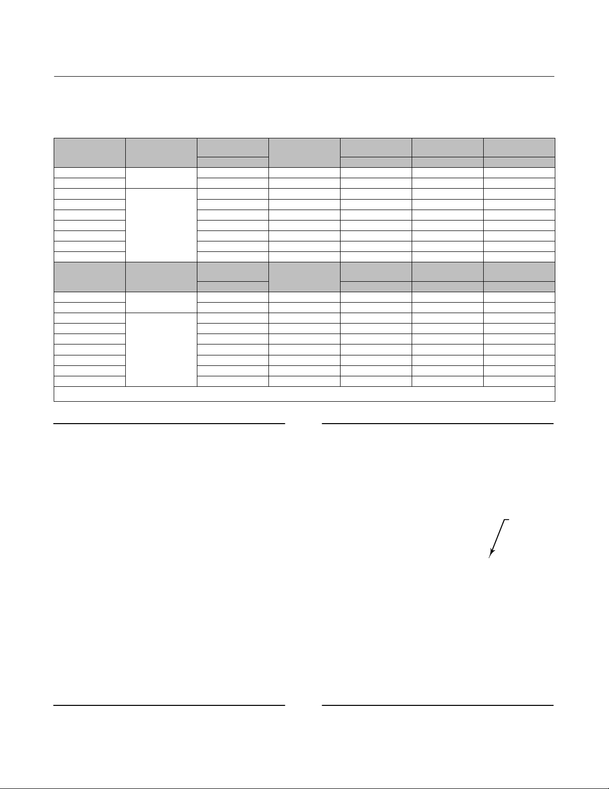
Table 9. Fisher 585C Handwheel Specifications
ACTUATOR SIZE
25
50 482 0.5 445 23,790 20
(1)
60
(2)
60
(1)
68
(2)
68
80 432 0.4 423 50000 35
100 432 0.4 623 75600 94
130 432 0.4 623 75600 123
ACTUATOR SIZE
25
50 19 12 100 5350 45
(1)
60
(2)
60
(1)
68
(2)
68
80 17 10 95 11250 77
100 17 10 140 17000 208
130 17 10 140 17000 272
1. 2 and 4 inch maximum travel constructions.
2. 8 inch maximum travel construction.
HANDWHEEL
MOUNTING
Top‐Mounted
Integral
Side‐Mounted
HANDWHEEL
MOUNTING
Top‐Mounted
Integral
Side‐Mounted
HANDWHEEL
DIAMETER
mm Newtons Newtons kg
356 0.5 325 12,810 17
203 0.6 276 40000 28
356 0.6 160 40000 30
203 0.6 276 40000 30
356 0.6 160 40000 33
HANDWHEEL
DIAMETER
Inches Pounds Pounds Pounds
14 12 73 2880 37
8 16 62 9000 61
14 16 36 9000 66
8 16 62 9000 66
14 16 36 9000 71
TURNS PER mm
TRAVEL
TURNS PER INCH
TRAVEL
MAXIMUM RIM
FORCE REQUIRED
MAXIMUM RIM
FORCE REQUIRED
HANDWHEEL
OUTPUT FORCE
HANDWHEEL
OUTPUT FORCE
585C Actuator
March 2021
HANDWHEEL
WEIGHT
HANDWHEEL
WEIGHT
Figure 2. Fisher 585C Piston Actuator
with Handwheel
E0410
Figure 3. Fisher 585C Piston Actuator
with Spring Return
PISTON
O‐RING
W7447‐1
9
Page 10

585C Actuator
March 2021
Instruction Manual
D102087X012
Actuator with Spring Return (figure 3)
585C size 25 and 50 actuators are available with bias springs in two configurations. The 585C actuator, with the bias
spring under the piston, fully retracts the actuator stem upon loss of cylinder pressure. The 585C actuator, with the
bias spring on top of the piston, fully extends the actuator stem upon loss of cylinder pressure. No additional parts are
required to convert from one actuator type to the other.
For more detailed information on the 3610 positioner and DVC6200 digital valve controllers, refer to the Principle of
Operation section in the 3610J Instruction Manual (D200149X012
)and DVC6200 instruction manuals.
Installation
WARNING
To avoid personal injury or property damage caused by cylinder fracture as a result of piston impact, install the stem
connector securely before supplying pressure to the positioner. Use only a regulator-controlled air supply to move the
actuator piston so that you can install the stem connector. Do not use the positioner to move the actuator piston before
installing the stem connector.
Always wear protective gloves, clothing, and eyewear when performing any installation operations to avoid personal
injury.
To avoid personal injury or property damage caused by bursting of pressure‐retaining parts, be certain the cylinder
pressure or other pressure ratings do not exceed the limits listed in table 1. Use pressure‐limiting or pressure‐relieving
devices to prevent cylinder pressure or other pressure ratings from exceeding these limits.
Check with your process or safety engineer for any additional measures that must be taken to protect against process
media.
If installing into an existing application, also refer to the WARNING at the beginning of the Maintenance sections in this
instruction manual.
When an actuator and valve are shipped together as a control valve assembly, the actuator is normally mounted on the
valve. Follow the valve instructions when installing the control valve in the pipeline. If the actuator is shipped
separately or if it is necessary to mount the actuator on the valve, perform the Actuator Mounting procedures in this
instruction manual corresponding to your actuator size. For information on mounting valve positioners, refer to the
3610J Instruction Manual (D200149X012) or DVC6200 instruction manuals for details.
If a 585C actuator is being installed without a positioner, the cylinder loading pressures should be supplied through a
4‐way solenoid valve or a switching valve. The bottom side of the piston is pressured through the bottom side of the
mounting flange on the actuator yoke (key 6, figures 4 and 6) for sizes 25 and 50 or the connection at the lower side of
the cylinder (key 1, figure 9 to 13) for sizes 60 to 130. The top side of the piston is pressured through the connection in
the cylinder cover (key 1 for figures 4, 6; and 9 to 13).
The supply pressure medium should be clean, dry filtered air. If the supply source is capable of exceeding the
maximum actuator operating pressure or positioner supply pressure, appropriate steps must be taken during
installation to protect the positioner and all connected equipment against overpressure.
WARNING
Dropping the actuator and any attached accessories and/or valve may cause personal injury and/or equipment damage. For
all mounting procedures use an adequately sized chain, sling, hoist, or crane to handle the actuator and any attached
accessories and/or valve. Use caution during lifting and handling to prevent slippage, swinging, faulty equipment
connections, or sudden shock loads.
10
Page 11

Instruction Manual
D102087X012
585C Actuator
March 2021
CAUTION
To avoid damage to actuator parts and difficult operation of actuator handwheels, open the bypass valve before using a
handwheel.
If manual operation is required, the actuator should be equipped with a manual handwheel. To manually move the
piston rod with the handwheel, first open the bypass needle valve (key 66 for sizes 25 and 50, figure 8; key 92 for sizes
60 to 130, figure 14), place the handwheel pointer in the neutral position, and insert the locking pin in the sleeve
assembly (for size 60‐130). Then turn the handwheel in the selected direction as indicated on the wheel.
The control valve should be located where it will be accessible for servicing. Room should be left above and below the
control valve to permit removal of the actuator and valve plug.
Bypass Assembly
The bypass is furnished as shown in figures 5, 7, 8, and 14 only when a handwheel actuator is specified. The bypass
allows the pressure to equalize on either side of the piston, so that the manual actuator can be used to position the
valve.
Flow through the bypass tubing is controlled by an angle needle valve (key 66 for figures 5, 7, and 8; and key 92 for
figure 14), which is operated manually. This valve should be closed when air pressure is being used to operate the
valve.
Three‐Way Valve Applications Note
WARNING
To avoid loss of control of process fluid and subsequent personal injury or property damage caused by bursting of
pressure‐retaining parts, be sure the cylinder pressure does not exceed 80 psig in high cycle‐rate, fast stroking speed,
three‐way valve applications.
In three‐way valve applications where the actuator fully strokes at a frequency of once per minute or faster, and the
stroking speed is rapid (less than 0.5 seconds per stroke), there is a possibility that the stem can fracture at the plug if
the actuator cylinder pressure is greater than 80 psig. This can cause loss of control of process fluid and further
damage to the actuator. Consideration should be given to the use of high‐strength, fatigue‐resistant stem materials in
these applications.
Actuator Mounting
Size 25 and 50 Actuator Mounting
The following procedure describes how to mount a 585C actuator size 25 and 50 on a push‐down‐to‐close valve so
that the piston stem to valve plug stem connection allows full travel and proper shutoff. Key numbers referenced in
the following steps are shown in figures 4 through 8.
11
Page 12

585C Actuator
March 2021
Instruction Manual
D102087X012
1. If not already removed, remove the stem connector (key 12) by loosening the cap screws (key 14).
2. Thread the stem connector nuts (keys 13 and 15) onto the valve stem, and run the nuts to the bottom of the valve
stem threads.
3. Push the valve plug stem until the valve plug is closed for push‐down‐to‐close valve plug action.
4. Place the actuator on the bonnet of the valve and secure the actuator tightly to the bonnet with the yoke locknut.
CAUTION
In the following procedure, do not rotate the valve plug while it is seated since this may cause damage to the seating
surface and thereby allow excessive leakage. Also, during adjustment, use tools carefully to avoid damaging the valve plug
stem. A damaged valve plug stem could cut the packing and allow leakage.
Note
When using an actuator with handwheel in the following step to stroke the valve plug, be sure the bypass valve (key 66, figure 5, 7,
or 8) is open. Rotating the handwheel (key 47, figure 5, 7, or 8) clockwise extends the actuator stem (key 10); rotating the
handwheel counterclockwise retracts the actuator stem.
5. Perform one of the following procedures (a or b as appropriate):
a. For a 585C actuator with spring retraction upon loss of cylinder pressure (figures 4 and 5) on a
push‐down‐to‐close valve, manually move the valve plug to the seated position. Rotate the handwheel or apply
pressure to the pressure connection in the cylinder (key 1) until the piston (key 3) and actuator stem (key 10)
move down the specified travel. Run the stem connector nut (key 13) up on the valve stem until it contacts the
actuator stem. Be sure the flats on the actuator stem are perpendicular to the scale indicator web on the yoke
(key 6). Adjust the stem connector nut as necessary, so that the flats on the nut and the actuator stem are
parallel. Clamp the actuator stem and stem connector nut together with the stem connector (key 12) and the
two cap screws and hex nuts (keys 14 and 23). Run the hex nut (key 15) up the valve stem and tighten against the
stem connector nut (key 13).
b. For a 585C actuator with spring extension upon loss of cylinder pressure (figures 6 and 7) with
push‐down‐to‐close valve, manually move the valve plug to the seated position. Run the stem connector nut
(key 13) up the valve stem until it contacts the actuator stem (key 10). Rotate the handwheel or apply pressure
to the pressure connection in the yoke (key 6) to move the actuator stem (key 10) approximately 1/4 inch away
from the stem connector nut. Rotate the stem connector nut so that it moves up the valve stem two full turns.
Manually move the valve plug so that the stem connector nut again contacts the actuator stem. Be sure the flats
on the actuator stem are perpendicular to the scale indicator web on the yoke (key 6). Adjust the stem connector
nut, as necessary, so that the flats on the nut and the actuator stem are parallel. Clamp the actuator stem and
stem connector nut together with the stem connector (key 12) and the two cap screws and hex nuts (keys 14
and 23). Run the hex nut (key 15) up the valve stem and tighten it against the stem connector nut (key 13).
6. Cycle the actuator several times to check for proper operation.
Note
In the following step, make sure the correct travel indicator scale (key 19) is used per the Parts List for the desired travel.
7. If necessary, remove the travel indicator scale screws (key 18) and reposition the travel indicator scale (key 19) so
that the scale arrow points in the same direction as the valve plug moves when opening. Close the valve. Adjust the
scale up or down so that the stem connector (key 12) indicator lines up with the closed mark on the scale. Secure
the scale with the scale screws.
12
Page 13

Instruction Manual
D102087X012
585C Actuator
March 2021
Size 60‐130 Actuator Mounting
The following procedure describes how to mount a 585C size 60 to 130 actuator on a push‐down‐to‐close valve so
that the piston stem to valve plug stem connection allows full travel and proper shutoff. Key numbers referenced in
the following steps are shown in figures 9 through 13.
If an actuator is purchased separately for field installation on a control valve, mount it on the valve and secure it in
place with the yoke locknut for size 60 and 68 or with eight bolts on actuator sizes 80, 100, and 130 which use a 127
mm (5‐inch) yoke boss.
The stem connector should then be set up to clamp the actuator stem and valve plug stem together to provide the
proper valve travel. This procedure is outlined in the Stem Connector Assembly procedures of this instruction manual.
Stem Connector Assembly (Size 60‐130)
CAUTION
To avoid damaging the seating surfaces, do not rotate the valve plug while it is seated. Also avoid damage to the valve plug
stem by careful use of tools during travel adjustment.
WARNING
D To avoid personal injury or property damage caused by cylinder fracture as a result of piston impact, install the stem
connector securely before supplying pressure to the positioner. Incomplete engagement of valve stem and/or actuator
stem in the stem connector can result in stripped threads or improper operation. Be sure that the length of each stem
clamped in the stem connector is equal to or greater than the diameter of that stem. Do not loosen the cap screws
when the stem connector has spring or loading pressure force applied to it.
D Install the stem connector securely before a positioner is mounted to the actuator and pressurized, using only a
regulator- controlled air supply, not the positioner, to move the actuator piston to position the actuator stem.
D To avoid personal injury or property damage, keep hands and tools out of the actuator stem travel path while
pressuring the actuator to move the actuator stem in the following steps.
585C Size 60‐130 Direct‐Acting (Push‐Down‐to‐Close) Valves
1. With the valve assembled and the actuator mounted, make sure the valve plug is in the closed position, and the
actuator is at the top of its stroke. Then screw the two stem locknuts (key 15) all the way onto the stem thread and
place the travel indicator disk (key 32) (if any) on the stem locknuts.
2. Keeping your hands away from any moving parts, use a regulator-controlled air supply to move the actuator stem
(key 10) down from the top of its stroke to the specified valve travel.
3. Using one half of the stem connector (key 12), align the actuator stem and the valve stem with threads from both
stems mated root-to-crest with the stem connector. Install the other half of the stem connector and tighten the cap
screws. With the stem locknuts (key 15), raise the travel indicator disk (key 32) to the stem connector (key 12).
4. Cycle the actuator to check availability of desired total travel and that the valve plug seats before the actuator
contacts the lower travel stop. Minor travel adjustments can be made by loosening the stem connector (key 12)
slightly, tightening the locknuts (key 15) together, and screwing the valve stem either into or out of the stem
connector (key 12) with a wrench on the locknuts (key 15). If the valve stem cannot be turned, as with a bellows seal
bonnet, remake the stem connection to achieve the desired travel.
5. Once the total travel is adequate, tighten the stem connector (key 12) securely, lock the stem locknuts (key 15)
against the connector, and adjust the indicator scale (key 19) on the yoke to show correct valve plug position.
13
Page 14

585C Actuator
March 2021
6. Provide a gauge to measure the pressure to the actuator. Make a final adjustment of the actuator or its positioner to
set the starting point of valve travel and to obtain full travel for the given instrument range.
Instruction Manual
D102087X012
585C Size 60‐130 Reverse‐Acting (Push‐Down‐to‐Open) Valves
1. Keeping your hands away from moving parts, pressure the actuator, using a regulator-controlled air supply, to
move the actuator stem (key 10) to the extreme upward position then reverse loading pressure to lower the
actuator stem (key 10) approximately 3 mm (1/8 inch).
2. Pull the valve stem up to seat the valve plug.
3. Using one half of the stem connector (key 12), align the actuator stem and the valve stem with threads from both
stems mated root-to-crest with the stem connector. Install the other half of the stem connector and tighten the cap
screws.
4. If there is a travel indicator disk (key 32), raise it to the stem connector (key 12) and tighten in position with the
stem locknuts (key 15). The indicator disk (key 32) should show the valve to be open with the piston (key 3) at the
bottom of its stroke. If it does not, loosen two screws (key 18) and shift the travel indicator scale (key 19) to indicate
OPEN.
5. Cycle the actuator to check availability of desired total travel and that the valve plug seats before the actuator
contacts the upper travel stop. Minor travel adjustments can be made by loosening the stem connector (key 12)
slightly, tightening the locknuts (key 15) together, and screwing the valve stem either into or out of the stem
connector (key 12) with a wrench on the locknuts. If the valve stem cannot be turned, as with a bellows seal bonnet,
remake the stem connection to achieve the desired travel.
6. Once the total travel is adequate, tighten the stem connector (key 12) securely, lock the stem locknuts (key 15)
against the connector, and adjust the indicator scale (key 19) on the yoke to show correct valve plug position.
7. Provide a gauge to measure the pressure to the actuator. Make a final adjustment of the actuator or its positioner to
set the starting point of valve travel and to obtain full travel for the given instrument range.
585C Handwheels
Handwheel Operation (Sizes 25 and 50)
Key numbers referenced in the following steps are shown in figures 5, 7, and 8 for the 585C actuator.
The handwheel assembly on a 585C actuator may be used as an adjustable travel stop to limit full upward or
downward travel of the actuator stem (key 10), or as a manual actuator to fully stroke the valve. When the neutral
indicator (key 42) is in the neutral position, travel is not restricted. With clockwise handwheel (key 47) rotation, the
operating nut (key 46) is screwed downward, forcing the actuator stem (key 10) down. With counterclockwise
rotation, the operating nut is screwed upward against the handwheel stem washer (key 45), pulling the actuator stem
up.
Note
When using an actuator with handwheel to stroke the valve plug or position the travel stop, be sure the bypass valve (key 66) is
open.
Handwheel Operation (Sizes 60‐130)
The 585C handwheel assembly for sizes 60 through 130 actuators (figures 9 and 10) has three main functions:
14
Page 15

Instruction Manual
D102087X012
585C Actuator
March 2021
a. To open or close the valve manually or to position the valve at any point in the stroke, regardless of the cylinder
pressure. The tapered pin is inserted during manual throttling operation.
b. To act as a travel stop to limit full opening or closing of the valve but not both at the same time. The tapered pin
is left out when the assembly is used as a travel stop.
c. To open or close the valve manually in an emergency without the necessity of inserting the tapered pin.
Bevel gears are used in sizes 60 and 68 and worm gears in sizes 80 through 130. A spring‐loaded ball detent is provided
in the handwheel to prevent a change in setting due to vibration. The following table 10 lists pertinent information on
these handwheel units.
Table 10. Handwheel Information
Actuator Size 60‐68 80‐130
Handwheel Diameter, Inches 8 17
Turns Required for One Inch of Travel 16 10
Maintenance (Sizes 25 and 50)
Actuator parts are subject to normal wear and must be inspected and replaced as necessary. The frequency of
inspection and replacement depends on the severity of service conditions. This section provides two separate
procedures, one on Replacing Handwheel Housing O‐Ring or Thrust Bearings, and the other on Replacing Seals,
Changing Action, or Changing Bias Spring(s).
Refer to figures 5 and 7.
For an actuator with handwheel, a grease fitting (key 50) is provided on the bearing cover (key 38) for periodic bearing
lubrication with lithium grease (key 24).
WARNING
Avoid personal injury from sudden release of process pressure. Before performing any maintenance operations:
D Do not remove the actuator from the valve while the valve is still pressurized.
D Always wear protective gloves, clothing, and eyewear when performing any maintenance operations to avoid personal
injury.
D Disconnect any operating lines providing air pressure, electric power, or a control signal to the actuator. Be sure the
actuator cannot suddenly open or close the valve.
D Use bypass valves or completely shut off the process to isolate the valve from process pressure. Relieve process pressure
on both sides of the valve. Drain the process media from both sides of the valve.
D Vent the power actuator loading pressure and release all bias spring compression force by slowly unscrewing the
cylinder cover bolting in a crisscross pattern.
D Use lock‐out procedures to be sure that the above measures stay in effect while you work on the equipment.
D The valve packing box may contain process fluids that are pressurized, even when the valve has been removed from the
pipeline. Process fluids may spray out under pressure when removing the packing hardware or packing rings, or when
loosening the packing box pipe plug.
D Check with your process or safety engineer for any additional measures that must be taken to protect against process
media.
15
Page 16

585C Actuator
March 2021
Instruction Manual
D102087X012
Replacing Handwheel Housing O‐Ring or Thrust Bearings
(Sizes 25 and 50)
Perform this procedure if inspecting or replacing the handwheel housing O‐ring, handwheel thrust bearings, or any
other handwheel parts located above the cylinder (key 1). Inspection or replacement of the cylinder O‐ring, handwheel
stem, or handwheel stem jam nut (key 57, 56, or 52) are covered in the Replacing Seals, Changing Action, or Changing
Bias Spring(s) procedure. Key numbers are referenced in figure 5 for a 585C actuator (spring retracts actuator rod) and
in figure 7 for a 585C actuator (spring extends actuator rod).
Note
This procedure may be performed without removing the cylinder, or yoke (key 1 or 6) from the bonnet of the valve.
Disassembly
Isolate the control valve from the line pressure, release pressure from both sides of the valve body, and drain the
process media from both sides of the valve. Shut‐off all pressure lines and power to the actuator, and release all
pressure from the actuator. Use lock‐out procedures to be sure that the above measures stay in effect while you work
on the equipment.
WARNING
Refer to the WARNING at the beginning of the Maintenance section in this instruction manual.
1. Shut off the bypass valve (key 66). Remove the cylinder pressure piping and bypass tubing from the bypass tees
(key 68) on the cylinder (key 1).
2. Turn the handwheel (key 47) in the appropriate direction so the neutral indicator (key 42) is behind the NEUTRAL
position of the neutral indicator plate (key 37).
3. Unscrew and remove the neutral indicator cover (key 35).
4. Remove the handwheel retaining ring, handwheel, and locking key (keys 48, 47, and 65).
5. Loosen the bearing cover set screws (key 51), and unscrew and carefully remove the bearing cover (key 38).
6. Remove the handwheel housing O‐ring (key 58) and the top set of thrust bearings (key 39).
7. Since both the handwheel housing (key 36) and the operating nut (key 46) have left‐hand threads, unscrew the
handwheel housing by turning it clockwise off the operating nut. Carefully remove the detent ball and detent spring
(keys 64 and 63), and remove the bottom set of thrust bearings (key 39).
8. Unscrew the handwheel stem cap screw (key 60) while using a 7/8 inch wrench to hold the handwheel stem
(key 56). Remove the handwheel stem washer (key 45), and the operating nut (key 46) with attached neutral
indicator (key 42).
9. Unscrew the neutral indicator (key 42) counterclockwise if necessary to separate it from the operating nut (key 46).
Reassembly
1. If the neutral indicator (key 42) was removed, coat its threads with thread locking adhesive (medium strength)
(key 70) and screw it into the operating nut (key 46). Position the 90‐degree elbow of the neutral indicator so that it
will not interfere with the neutral indicator cover (key 35) when assembled.
2. If necessary, replace the anti‐rotation key (key 40), by pushing the key outward from the cylinder (key 1) then install
the replacement key (key 40) into the anti‐rotation hole of the cylinder.
16
Page 17

Instruction Manual
D102087X012
3. Lubricate the inside surface of the operating nut (key 46) with lithium grease (key 24). Install the operating nut with
the attached neutral indicator, and the handwheel stem washer (key 45), onto the handwheel stem (key 56) and
secure with the handwheel stem cap screw (key 60). Tighten the cap screw to 169 NSm (125 lbfSft).
4. Place the bottom set of thrust bearings (key 39) on top of the cylinder (key 1). Insert the detent spring and ball
(keys 63 and 64) into the cylinder.
5. Install the handwheel housing O‐ring (key 58) on the handwheel housing (key 36). Since both the handwheel
housing and the operating nut (key 46) have left‐hand threads, thread the handwheel housing onto the operating
nut by turning it counterclockwise over the operating nut until the handwheel housing is snug against the bottom
set of thrust bearings (key 39).
6. Install the top set of thrust bearings (key 39) over the handwheel housing (key 36).
7. Carefully slide the bearing cover (key 38) over the handwheel housing (key 36) and thread the bearing cover hand
tight onto the cylinder (key 1). Secure by tightening the set screws (key 51) to 18 NSm (13 lbfSft).
8. Install the locking key, handwheel, and handwheel retaining ring (keys 65, 47, and 48).
9. Screw the neutral indicator cover (key 35) hand tight only onto the handwheel housing (key 36).
10. Install the bypass tubing with attached bypass valve (key 66) into the bypass tees (key 68) in the cylinder (key 1).
585C Actuator
March 2021
Replacing Seals, Changing Action, or Changing Bias Spring(s)
(Sizes 25 and 50)
Key numbers are referenced in figures 4 and 5 for a 585C actuator (spring retracts actuator rod) and in figures 6 and 7
for a 585C actuator (spring extends actuator rod).
Disassembly
Isolate the control valve from the line pressure, release pressure from both sides of the valve body, and drain the
process media from both sides of the valve. Shut‐off all pressure lines and power to the actuator, release all pressure
from the actuator, and release all bias spring compression force by slowly unscrewing the cylinder cover bolting in a
crisscross pattern. Use lock‐out procedures to be sure that the above measures stay in effect while you work on the
equipment.
WARNING
Refer to the WARNING at the beginning of the Maintenance section in this instruction manual.
For 585C actuators with push‐only handwheel, figure 8, be sure the handjack stem is backed out of the cylinder as far
as it will go to relieve any extra spring compression.
1. Remove the cylinder pressure piping. With a handwheel construction, perform steps 1. through 2. of the
Replacing Handwheel Housing O‐Ring or Thrust Bearings procedure.
Note
In the following step, loosen each cylinder‐to‐yoke cap screw a slight amount in turn in a crisscross pattern to keep the cylinder
square with the yoke while relieving spring precompression.
2. While carefully allowing bias spring precompression to be slowly released, remove the cylinder‐to‐yoke cap screws
and cylinder cover (keys 2 and 1).
17
Page 18

585C Actuator
March 2021
Instruction Manual
D102087X012
CAUTION
When performing the following step, set the cylinder on a protective surface to prevent damage to the cylinder surfaces.
3. Remove the cylinder (key 1). Set the cylinder on a protective surface to prevent damage to the cylinder surfaces.
With a handwheel construction, inspect the cylinder O‐ring (key 57) and replace it if necessary, applying lithium
grease (key 24) to the replacement O‐ring.
4. Inspect the piston O‐ring (key 8) and replace, if necessary. If the only further maintenance to be performed is
replacement of the piston O‐ring, skip to step 3 of this procedure.
Note
585C actuators may be used with or without the bias springs. In the following procedures, references are made to the bias springs.
If the bias springs are not used, disregard references to them when performing the maintenance procedures.
5. Perform one of the following disassembly procedures (a, b, c, d, or e, as appropriate):
a. For 585C actuators without handwheel (If the bias spring is present, it extends the piston rod.) (figure 6), remove
the piston cap screw (key 4), piston (key 3), bias spring(s) (key 16 and/or key 17), and travel stop spacer (key 5).
b. For 585C actuators with handwheel (If the bias spring is present, it extends the piston rod.) (figure 7), remove the
handwheel stem (key 56) with attached piston stud (key 69), piston (key 3), bias spring(s) (key 16 and/or key 17),
and travel stop spacer (key 5).
c. For 585C actuators without handwheel (If the bias spring is present, it retracts the piston rod.) (figure 4), remove
the bias spring(s) (key 16 and/or key 17), piston cap screw (key 4), travel stop spacer (key 5) and piston (key 3).
d. For 585C actuators with handwheel (If the bias spring is present, it retracts the piston rod.) (figure 5), remove the
bias spring(s) (key 16 and/or key 17), the handwheel stem (key 56) with attached piston stud (key 69), travel
stop spacer (key 5), and piston (key 3).
e. For 585C actuators with push‐only handwheel (figure 8), remove the cotter pin and slotted nut (keys 73 and 72)
and lift off the handwheel. Remove the jam nut (key 52). Remove the cap screws (key 60) and lift off the
handwheel housing (key 36). Back the handwheel stem (key 56) out of the housing. Inspect the O‐rings (keys 57
and 58). Replace these parts as necessary.
6. If inspection or replacement of the actuator stem O‐ring or bearing (key 9 or 11) is necessary, perform steps 1.
through 7. Otherwise, skip to step 2, being sure to comply with the note preceding step 2.
7. Loosen the two cap screws in the stem connector (key 14) and remove it. If the actuator is mounted on a valve,
separate the actuator stem (key 10) from the valve plug stem. Remove the actuator from the valve.
8. To inspect the actuator stem bearing (key 11), actuator stem O‐ring (key 9), or backup ring (key 25, size 50 only)
remove the actuator stem (key 10) from the yoke (key 6). Replace these parts if necessary. Apply lithium grease
(key 24) to the replacement O‐ring or bearing and install it into the yoke.
Assembly
1. Install the actuator stem through the yoke.
Note
Make certain the travel indicator scale (key 19) correctly matches the travel per the Parts List.
18
Page 19

Instruction Manual
D102087X012
585C Actuator
March 2021
2. To achieve the desired construction (either a direct‐acting or a reverse‐acting 585C actuator), perform one of the
following assembly procedures (a, b, or c, as appropriate):
a. For 585C actuators (bias spring retracts the piston rod) (figures 4 and 5), center the inner bias spring, if used,
(key 17 per table 6 or 7) around the center boss in the yoke (key 6). If used per table 6 or 7, center the outer bias
spring (key 16) around the inner bias spring. The outer bias spring should be within the outer boss in the yoke.
Put the travel stop spacer and the piston (keys 5 and 3) on the actuator stem. Apply lithium grease (key 24) to
the threads of the piston cap screw or piston stud (key 4 or 69). Insert the piston cap screw, or stud plus attached
handwheel stem (key 56), through both the piston and travel stop spacer and into the actuator stem. Use a
wrench on the flats of the actuator stem to prevent it from turning. Tighten the piston cap screw, or stud plus
attached handwheel stem, to 102 NSm (75 lbfSft) for size 25 actuators or 136 NSm (100 lbfSft) for size 50
actuators.
b. For 585C actuators with push‐only handwheel (figure 8), lubricate the O‐rings and handjack stem threads with
lithium grease. Install the O‐ring (key 57) and handjack stem (key 56), turning the screw into the housing as far as
possible. Place the O‐ring (key 58) over the housing and insert into the cylinder (key 1). Replace the cap screws
(key 60) and tighten to 41 NSm (30 lbfSft) on size 25 actuators or 81 NSm (60 lbfSft) on size 50 actuators. Replace
the jam nut (key 52), handwheel (key 47), and slotted nut and cotter pin (keys 72 and 73).
c. For 585C actuators (bias spring extends the piston rod) (figures 6 and 7), put the piston (key 3) on the actuator
stem and the travel stop spacer (key 5) on the piston. Apply lithium grease (key 24) to the threads of the piston
cap screw or piston stud (key 4 or 69). Insert the piston cap screw, or stud plus attached handwheel stem (key
56), through both the travel stop spacer and piston and into the actuator stem. Use a wrench on the flats of the
actuator stem to prevent it from turning. Tighten the piston cap screw, or stud plus attached handwheel stem,
to 102 NSm (75 lbfSft) for size 25 actuators or 136 NSm (100 lbfSft) for size 50 actuators. Center the inner bias
spring, if used, (key 17 per table 4 or 5) around the travel stop spacer. If used per table 4 or 5, center the outer
bias spring (key 16) around the inner bias spring. The outer bias spring should be within the outer boss on the
piston.
3. Install the piston O‐ring (key 8) if it was removed from the piston, and the yoke O‐ring (key 7, figure 4 or 6) if it was
removed from the yoke (key 6). Apply lithium grease (key 24) to the wall of the cylinder (key 1) and carefully slide
the cylinder over the piston O‐ring. Be sure the cylinder pressure connection is aligned with the yoke pressure
connection. Square the cylinder in place over the yoke O‐ring.
4. Line up the cylinder holes with the yoke holes making sure for a handwheel construction that the anti‐rotation
groove in the handwheel stem (key 56) is aligned with the hole in the cylinder for the anti‐rotation key (key 40).
Note
When placing the cylinder on the yoke and tightening the cylinder‐to‐yoke bolts, be sure to keep the cylinder square and aligned
with the top of the yoke.
5. Lubricate the cylinder‐to‐yoke bolts (key 2) with lithium grease (key 24). In a criss cross pattern, alternately tighten
each cylinder‐to‐yoke bolt a slight amount so that the cylinder stays square with the yoke. When all cylinder
surfaces are in contact with the yoke, tighten each cylinder‐to‐yoke bolt to 70 NSm (55 lbfSft) for a size 25 or 95
NSm (70 lbfSft) for a size 50.
6. With a handwheel construction, perform steps 2 through 10 of the Replacing Handwheel Housing O‐ring or Thrust
Bearings procedure.
7. If the actuator will be mounted on a valve, perform the appropriate actuator mounting procedure. Otherwise, place
the stem connector nut (key 13), stem connector (key 12), two cap screws (key 14), two hex nuts (key 23) and hex
nut (key 15) in a parts bag and attach the bag to the actuator yoke.
19
Page 20

585C Actuator
March 2021
Instruction Manual
D102087X012
Maintenance (Sizes 60‐130)
WARNING
To avoid personal injury or property damage caused by cylinder fracture as a result of piston impact, install the stem
connector securely before supplying pressure to the positioner. Use only a regulator-controlled air supply to move the
actuator piston so that you can install the stem connector. Do not use the positioner to move the actuator piston before
installing the stem connector.
WARNING
Avoid personal injury from sudden release of process pressure or uncontrolled process fluid. Before starting disassembly:
D Do not remove the actuator from the valve while the valve is still pressurized.
D Always wear protective gloves, clothing, and eyewear when performing any maintenance operations to avoid personal
injury.
D Disconnect any operating lines providing air pressure to the actuator. Be sure the actuator cannot suddenly open or
close the valve.
D Use bypass valves or completely shut off the process to isolate the valve from process pressure. Relieve process pressure
on both sides of the valve. Drain the process media from both sides of the valve.
D Vent the power actuator loading pressure.
D Use lock‐out procedures to be sure that the above measures stay in effect while you work on the equipment.
D The valve packing box may contain process fluids that are pressurized, even when the valve has been removed from the
pipeline. Process fluids may spray out under pressure when removing the packing hardware or packing rings, or when
loosening the packing box pipe plug.
D Check with your process or safety engineer for any additional measures that must be taken to protect against process
media.
Key numbers indicated refer to figures 9 through 13.
Isolate the control valve from the line pressure, release pressure from both sides of the valve body, and drain the
process media from both sides of the valve. Shut‐off all pressure lines and power to the actuator, and release all
pressure from the actuator. Use lock‐out procedures to be sure that the above measures stay in effect while you work
on the equipment.
1. If positioner is not used, go to step 5. If positioner is used, shut off all pressure lines to the positioner then remove
all tubing lines (cylinder, instrument and supply) from the positioner.
CAUTION
Do not use wrenches or other tools directly on the valve stem. Damage to the stem surface could result in subsequent
damage to the valve packing.
2. Remove the stem connector (key 12) and the piston rod boot (key 29) used to protect the lower end of the actuator
stem.
3. Remove the socket head cap screws that hold the cylinder (key 1) to the yoke (key 6).
CAUTION
Exercise care in the following step to prevent damage to the cylinder wall during removal of the cylinder from the yoke.
20
Page 21

Instruction Manual
D102087X012
4. Insert a screwdriver in the two slots on the lower edge of the cylinder casting and pry the cylinder loose from the
yoke. Remove the cylinder, being careful not to mar the cylinder wall.
5. The piston (key 3) and actuator stem (key 10) will come out with the cylinder. The piston can then be removed by
forcing it out the open end of the cylinder.
6. Unscrew the seal bushing (key 110 or 26), in the upper end of the yoke (key 6).
7. With the unit disassembled, inspect all parts for excessive wear. Replace all worn O‐rings. Lubricate with lithium
grease for standard service and Krytox
assembly drawings. Apply sealant (key 70) as indicated on the assembly drawings.
8. When reassembling the actuator after the piston nut (key 4) has been removed from the actuator stem (key 10),
clean the threads of the piston nut thoroughly and apply thread sealant to the threads. Tighten the piston nut
securely to a torque of 237 NSm (175 lbfSft) for size 60 actuators, 1290 NSm (950 lbfSft) for size 68, 80, and 100
actuators, or 2070 NSm (1530 lbfSft) for size 130 actuators.
®
GPL 202 for low ambient temperature service (key 24) as indicated on the
585C Actuator
March 2021
Side‐Mounted Handwheel Maintenance (Sizes 60‐130)
Refer to figure 9 and 10.
1. The handwheel gears should be lubricated periodically. A grease fitting (key 140) is provided on sizes 80, 100, and
130. On sizes 60 and 68, remove the handwheel (key 118) and the bevel pinion (key 116) and pack the gear case
with lithium grease. Loosen the set screw (key 139) before attempting to remove the pinion and extension.
2. If it is necessary to change the valve plug action from push‐down‐to‐close to push‐down‐to‐open or vice versa,
change the handwheel arrangement so that the arrow indicates the correct rotation required to open the valve.
a. For sizes 60 and 68, remove the handwheel, invert and replace it. On sizes 60 and 68 (figure 9), remove and
replace the spring‐loaded ball assembly (key 123) in the opposite side.
b. For sizes 80‐100, remove the handwheel assembly and install in the opposite end of the gear case by unscrewing
the back and front worm retainers (keys 135 and 136, not shown) and turn the handwheel to disengage the
bevel pinion (key 116).
Disassembly of Handwheel Constructions (Sizes 60 and 68)
WARNING
Refer to the WARNING at the beginning of the Maintenance section (Sizes 60‐130) in this instruction manual.
To disassemble 585C piston actuators sizes 60 and 68 (with handwheel) for maintenance, perform the following
procedures (figure 9 and 10):
1. Be sure that all pressure is out of the cylinder and valve body.
2. Remove all tubing lines to the positioner.
3. Remove the cap screws (key 2) on the underside of either the cylinder flange (key 100) for size 60 or the adapter
flange (key 76) for size 68. Remove the cylinder (key 1).
4. Remove the piston nut (key 4), then use a mallet to tap the piston (key 3) off the piston connector (key 107).
5. Remove the handwheel extension (key 117) by loosening the set screw (key 139) and unscrewing the extension.
6. Remove the cap screws (key 2) holding the cylinder flange (key 100) to the yoke (key 6).
7. Lift the cylinder flange (key 100) off the yoke (key 6).
8. Inspect the handwheel gears and bearings as needed.
21
Page 22

585C Actuator
March 2021
9. To remove the actuator stem (not shown), loosen the stem connection (key 12) and pull the actuator stem out the
top of the sleeve assembly (key 104).
10. Remove the sleeve by screwing it out of the sleeve assembly (key 104).
11. Unscrew the seal bushing (key 110) to inspect the O‐rings (keys 9 and 27).
Instruction Manual
D102087X012
Disassembly of Handwheel Constructions (Sizes 80‐130)
WARNING
Refer to the WARNING at the beginning of the Maintenance section (Sizes 60‐130) in this instruction manual.
To disassemble 585C piston actuators sizes 80‐130 (with handwheel) for maintenance, perform the following
procedures (figure 10):
1. Be sure that all pressure is out of the cylinder and valve body.
2. Remove all tubing lines to the positioner.
3. Remove the cap screws (key 2) on the underside of the cylinder adapter (key 101) and remove the cylinder (key 1).
4. Remove the piston nut (key 4), then use a mallet to remove the piston (key 3) from the piston connector (key 107).
5. Remove the cap screws (key 127) and cylinder adaptor (key 101).
6. Remove the cap screws (key 128) and remove the spacer (key 102), being careful not to lose the key (key 144).
7. Remove the locking pin (key 131), disconnect the stem connector (key 12) and pull out the actuator stem.
8. Remove the pointer (key 129) and turn the sleeve out of the sleeve assembly (key 104).
9. Remove the cap screws (key 128) holding the gear case (key 103) to the yoke (key 6).
10. Lift the gear case (key 103) to expose the handwheel assembly.
Reassembly (Sizes 60‐130)
When reassembling the 585C piston actuator with side‐mounted handwheel, adjust the setscrew (key 125) to
eliminate play in gear bearings. When properly set, lock with key 126.
When reassembling the actuator after the piston nut (key 4) has been removed from the piston connector (key 107),
clean the threads of the piston nut thoroughly and apply thread sealant to the threads. Tighten the piston nut securely
to a torque of 237 NSm (175 lbfSft) for size 60 actuators, 1290 NSm (950 lbfSft) for size 68, 80, and 100 actuators, or
2070 NSm (1530 lbfSft) for size 130 actuators.
Parts Ordering
When corresponding with your Emerson sales office about this equipment, refer to the serial number found on the
actuator nameplate (key 21).
WARNING
Use only genuine Fisher replacement parts. Components that are not supplied by Emerson Automation Solutions should
not, under any circumstances, be used in any Fisher valve, because they may void your warranty, might adversely affect the
performance of the valve, and could cause personal injury and property damage.
22
Page 23

Instruction Manual
D102087X012
Parts Kits
Table 11. Standard Construction
Actuator Size Parts Kit Description Parts Kit Number
25
50 R585CX00502
60 (2‐inch maximum travel)
60 (4‐inch maximum travel)
60 (2‐, 4‐, and 8‐inch maximum travel w/ handwheel)
(8‐inch maximum travel)
68 (2‐, 4‐, and 8‐inch maximum travel w/ handwheel) O‐ring (contains keys 7, 8, 9, 27, and 112) R585CX00102
68 (2‐, 4‐, and 8‐inch maximum travel)
80 (8‐inch maximum travel)
80 (2‐, 4‐, and 8‐inch maximum travel w/ handwheel)
80 (4‐inch maximum travel)
100 (4‐inch maximum travel)
100 (8‐inch maximum travel)
4‐ and 8‐inch maximum travel w/ handwheel)
130 (4‐inch travel)
130 (8‐inch travel)
(4‐ and 8‐inch travel with handwheel)
O‐ring (contains keys 7, 8, and 9)
Backup ring (key 25) for size 50 actuators only
O‐ring (contains keys 7, 8, 9, and 27)
Piston rod boot (key 29) and Snap ring (keys 30 and 31)
O‐ring (contains keys 7, 8, 9, and 27)
Piston rod boot (key 29) and Snap ring (keys 30 and 31)
O‐ring (contains keys 7, 8, 9, and 27) R585CX00032
O‐ring (contains keys 7, 8, 9, and 27) R585CX00042
O‐ring (contains keys 7, 8, 9, and 27)
Piston rod boot (key 29) and Snap ring (keys 30 and 31)
O‐ring (contains keys 7, 8, 9, and 27)
Piston rod boot (key 29) and Snap ring (keys 30 and 31)
O‐ring (contains keys 7, 8, 9, and 27) R585CX00072
O‐ring (contains keys 7, 8, 9, and 27)
Piston rod boot (key 29) and Snap ring (keys 30 and 31)
O‐ring (contains keys 7, 8, 9, and 27) R585CX00092
R585CX00252
R585CX00012
R585CX00022
R585CX00052
R585CX00062
R585CX00082
585C Actuator
March 2021
Table 12. Low Ambient Temperature Construction
Actuator Size Parts Kit Description Parts Kit Number
60 (2, 4 and 8-inch maximum travel)
60 (2,4 and 8-inch maximum travel w/ handwheel)
68 (2, 4 and 8-inch maximum travel)
68 (2, 4 and 8-inch maximum travel w/ handwheel)
80 (2, 4 and 8-inch maximum travel)
80 (2, 4 and 8-inch maximum travel w/ handwheel)
100 (4 and 8-inch maximum travel) O-ring (contains key 7, 8, 9 and 27) R585CF00032
130 (4 and 8-inch maximum travel)
130 (4 and 8-inch maximum travel w/ handwheel)
O-ring (contains key 7, 8, 9 and 27)
lubricant (key 24)
O-ring (contains key 7, 8, 9 and 27)
lubricant (key 24)
O-ring (contains key 7, 8, 9 and 27)
lubricant (key 24)
R585CF00012
R585CF00022
R585CF00042
23
Page 24

585C Actuator
March 2021
Parts List
Note
Contact your Emerson sales office
Sizes 25 and 50
Common Actuator Parts (figure 4 or 6)
Key Description
1 Cylinder
2 Cylinder‐to‐Yoke Bolts
3 Piston
4 Cap Screw, for actuators without handwheel
5 Travel Stop Spacer
6 Yoke
7* Yoke O‐ring
8* Piston O‐ring
9* Actuator Stem O‐ring
10 Actuator Stem
11* Piston Stem Bearing
12 Stem Connector
13 Stem Connector Nut
14 Cap Screw (2 req'd)
15 Hex Nut
16 Bias Spring, outer (see table 4‐7 for use)
17 Bias Spring, inner (see table 4‐7 for use)
18 Self Tapping Screw (2 req'd)
19 Travel Indicator Scale
20 Drive Screw (7 req'd)
21 Nameplate
22 Warning Tag
23 Hex Nut (2 req'd)
24 Lithium grease (not furnished with actuator)
25* Back‐Up Ring, Size 50 only
71 Warning Nameplate
75 Spacer (2 req'd)
for Part Ordering information.
Instruction Manual
D102087X012
Additional Parts for Actuator with
Handwheel (figure 5 ,7, or 8)
Key Description
1 Cylinder,
35 Neutral Indicator Cover
36 Handwheel Housing
37 Neutral Indicator Plate
38 Bearing Cover
39 Thrust Bearing
40 Anti‐rotation Key
42 Neutral Indicator
43 Neutral Indicator Plate Screw (2 req'd)
45 Handwheel Stem Washer
46 Operating Nut
47 Handwheel
48 Handwheel Retaining Ring
50 Grease Fitting
51 Bearing Cover Set Screw (3 req'd)
52 Handwheel Jam Nut
53 Button Plug
56 Handwheel Stem
57* Cylinder Cover O‐Ring - For Push Only
58* Handwheel Housing O‐Ring - For Push Only
60 Handwheel Stem Cap Screw,
(4 req'd for size 25), (3 req'd for size 50)
63 Detent Spring
64 Detent Ball
65 Locking Key
66 Bypass Valve
67 Bypass Tubing
68 Bypass Tee
69 Piston Stud
70 Thread locking adhesive (medium strength)
(not furnished with actuator)
72 Hex Nut, Slotted
73 Cotter Pin
74 Elbow, Tube
24
*Recommended spare parts
Page 25
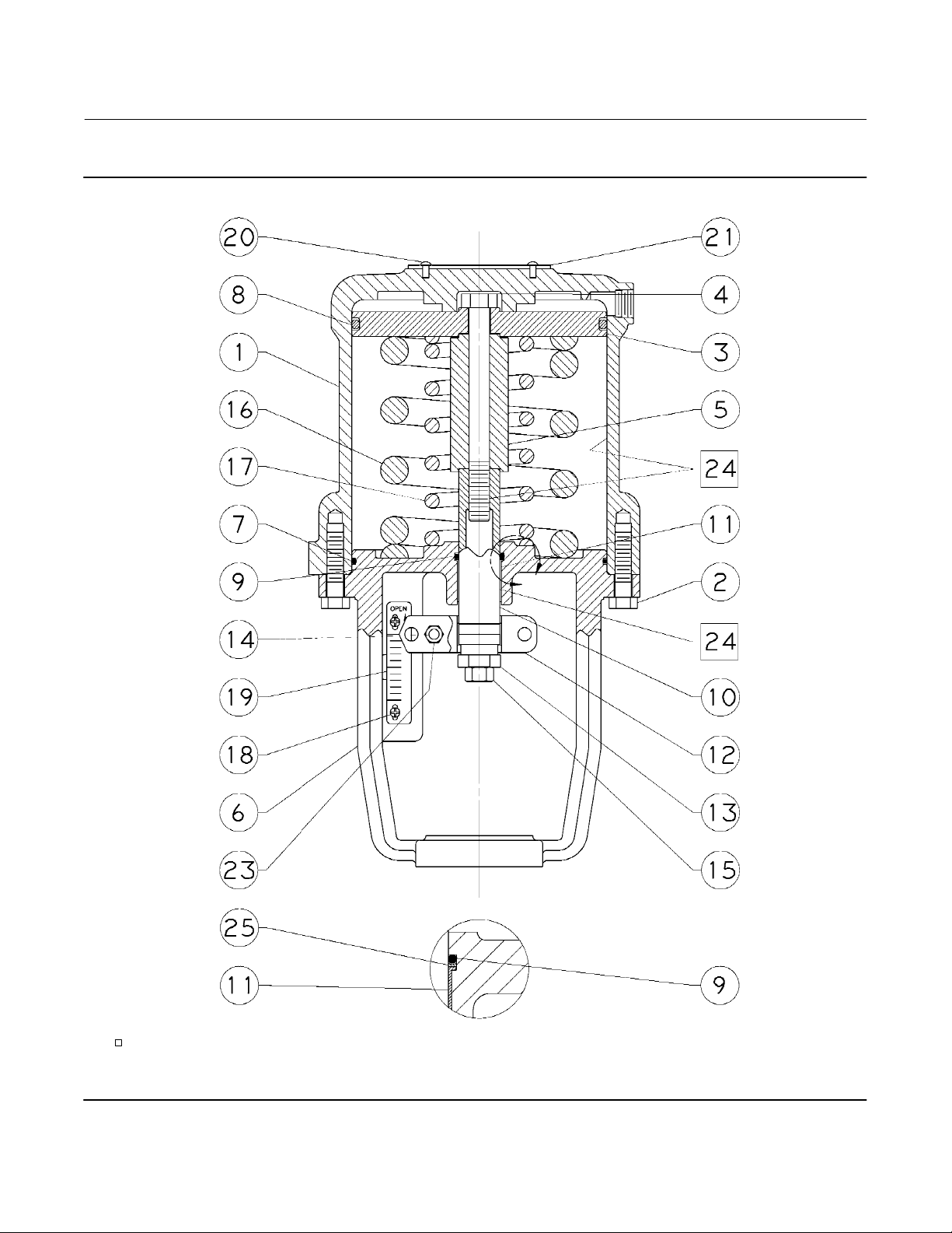
Instruction Manual
D102087X012
Figure 4. Fisher 585C Size 25 and 50 Actuators (spring retracts actuator rod)
585C Actuator
March 2021
A
APPLY LUB
NOTE:
KEY NUMBERS 22 AND 71 NOT SHOWN
44B6335‐C
VIEW A
SIZE 50
25
Page 26

585C Actuator
March 2021
Instruction Manual
Figure 5. Fisher 585C Size 25 and 50 Actuators Handwheel Assembly (spring retracts actuator rod)
D102087X012
26
APPLY LUB
44B6330‐B
HANDWHEEL ASSEMBLY
Page 27

Instruction Manual
D102087X012
Figure 6. Fisher 585CR Size 25 and 50 Actuators (spring extends actuator rod)
585C Actuator
March 2021
APPLY LUB
NOTE:
KEY NUMBERS 22 AND 71 NOT SHOWN
44B6319‐D
A
VIEW A SIZE 50
27
Page 28

585C Actuator
March 2021
Instruction Manual
Figure 7. Fisher 585CR Size 25 and 50 Actuators Handwheel Assembly (spring extends actuator rod)
D102087X012
APPLY LUB, SEALANT
44B6337‐C
28
HANDWHEEL ASSEMBLY
Page 29

Instruction Manual
D102087X012
Figure 8. Fisher 585C Size 25 and 50 Actuators Handwheel Assembly—Direct Acting, Push Only
(spring retracts actuator rod)
585C Actuator
March 2021
APPLY LUB
34B8587‐B
HANDWHEEL ASSEMBLY
29
Page 30

585C Actuator
March 2021
Instruction Manual
D102087X012
Sizes 60‐130 (figures 9-14)
Key Description
1 Cylinder Assembly
2 Cap Screw
3 Piston
4 Piston Nut
6 Yoke
7* O‐Ring
8* O‐Ring
9* O‐Ring
10 Actuator Stem
12 Stem Connector Assembly
15 Hex Nut
18 Screw (2 req'd)
19 Travel Indicator Scale
20 Drive Screw
21 Nameplate
22 Warning Nameplate (not shown)
24 Lithium grease for standard service and for handwheel locations
in all services (not furnished with actuator)
24 Krytox GPL 202 for cylinder and o-ring locations for low ambient
temperature service (not furnished with actuator)
26* Lower Seal Bushing
27* O‐Ring
28* Wiper Scraper
29* Piston Rod Boot
30* Snap Ring
31* Snap Ring
32 Travel Indicator Disk
33 Twin Speed Nut (not shown)
34 Machine Screw
70 Thread sealant (not furnished with actuator)
76 Adaptor Flange
76 Cylinder Flange
77 Cap Screws
90 Pipe Nipple (not shown)
91 Pipe Tee
92 Needle Valve
100 Cylinder Flange
101 Cylinder Adaptor
102 Spacer
103 Gear Case
104 Sleeve Assembly
105 Sleeve
Key Description
106 Actuator Stem
107 Piston Connector
108 Piston Ring Adaptor
109 Washer
110* Upper Seal Bushing
111 Retaining Ring
112* O‐Ring
113 Bearing Retainer
114 Bevel Gear
114 Worm Gear
115 Thrust Bearing (2 req'd)
116 Bevel Pinion
116 Worm Shaft
117 Extension
118 Handwheel
119 Handwheel Cap
119 Hex Nut (1 req'd)
120 Lockwasher
121 Spring Cap
122 Spring
123 Ball
123 Cover Screw
124 Combination Bearing
125 Set Screw
126 Hex Nut
127 Cap Screw
128 Cap Screw
129 Pointer
130 Handjack Indicator
131 Locking Pin
132 Chain
133 Drive Screw
134 Ball Bearing
135 Front Worm Retainer
136 Back Worm Retainer
137 Hand Grip
138 Hand Grip Bolt
139 Set Screw
140 Zerk Fitting
141 Ring
142 Machine Screw (2 req'd)
143 Key
144 Key
145 Caution Tag (not shown)
146 Cable Tie (2 req'd) (not shown)
30
*Recommended spare parts
Page 31

Instruction Manual
D102087X012
Figure 9. Fisher 585C Actuator with Integral Handjack Size 68 with 2‐ and 4‐Inch Travel
585C Actuator
March 2021
APPLY LUB/SEALANT
PARTS NOT SHOWN: 33, 145, 146
FOR BYPASS ASSEMBLY, SEE FIGURE 14
58B1370‐A
31
Page 32

585C Actuator
March 2021
Figure 10. Fisher 585C Actuator with Integral Handjack Size 80 and 100 with 4‐Inch Travel
SECTION A—A
Instruction Manual
D102087X012
APPLY LUB/SEALANT
PARTS NOT SHOWN: 141, 145, 146
FOR BYPASS ASSEMBLY, SEE FIGURE 14
58B1373‐A
32
A
A
Page 33
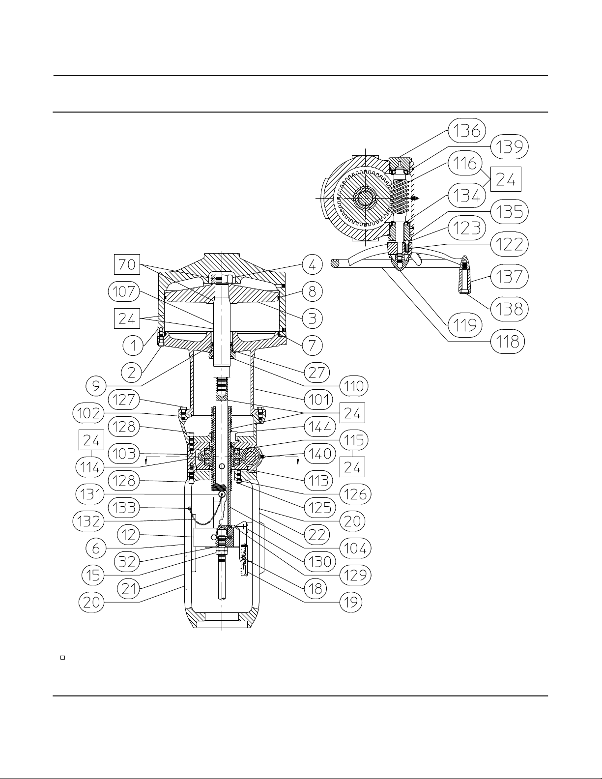
Instruction Manual
D102087X012
Figure 11. Fisher 585C Actuator with Integral Handjack Size 130 with 4‐Inch Travel
SECTION A—A
585C Actuator
March 2021
A
APPLY LUB/SEALANT
PARTS NOT SHOWN: 141, 145, 146
FOR BYPASS ASSEMBLY, SEE FIGURE 14
58B1375-1
58B1378-2
A
33
Page 34

585C Actuator
March 2021
Figure 12. Fisher 585C Actuator Size 60 with 2‐ and 4‐Inch Travel
Instruction Manual
D102087X012
APPLY LUB/SEALANT
PARTS NOT SHOWN: 33
58B1365‐A
34
Page 35

Instruction Manual
D102087X012
Figure 13. Fisher 585C Actuator Size 60 with 8‐Inch Travel and Size 68 with 2‐, 4‐, and 8‐Inch Travel
585C Actuator
March 2021
APPLY LUB/SEALANT
PARTS NOT SHOWN: 33
58B1366‐A
Figure 14. Fisher 585C Size 60‐130 Bypass Assembly
38B1397/A
35
Page 36

585C Actuator
March 2021
Instruction Manual
D102087X012
Neither Emerson, Emerson Automation Solutions, nor any of their affiliated entities assumes responsibility for the selection, use or maintenance
of any product. Responsibility for proper selection, use, and maintenance of any product remains solely with the purchaser and end user.
Fisher, FIELDVUE, and TopWorx are marks owned by one of the companies in the Emerson Automation Solutions business unit of Emerson Electric Co.
Emerson Automation Solutions, Emerson, and the Emerson logo are trademarks and service marks of Emerson Electric Co. All other marks are the property
of their respective owners.
The contents of this publication are presented for informational purposes only, and while every effort has been made to ensure their accuracy, they are not
to be construed as warranties or guarantees, express or implied, regarding the products or services described herein or their use or applicability. All sales are
governed by our terms and conditions, which are available upon request. We reserve the right to modify or improve the designs or specifications of such
products at any time without notice.
Emerson Automation Solutions
Marshalltown, Iowa 50158 USA
Sorocaba, 18087 Brazil
Cernay, 68700 France
Dubai, United Arab Emirates
Singapore 128461 Singapore
www.Fisher.com
36
E 2005, 2021 Fisher Controls International LLC. All rights reserved.
 Loading...