


Instruction Manual
D200157X012
4194HS IM
July 2022
Fisher™ 4194HS Differential Pressure Indicating
Controllers
Contents
Introduction 2.................................
Scope of Manual 2.............................
Description 2.................................
Specifications 5...............................
Educational Services 5.........................
Installation, Mounting, and Connections 5..........
Pipestand Mounting 6.........................
Pressure Connections 6........................
Process Pressure Connections 7.................
Vent Connection 8............................
Supply Pressure 9.............................
Remote Set Point
(suffix letter M) Connection 9.................
Controller Operation 9..........................
Adjustments 11...............................
Remote Set Point (suffix letter M) 11..........
Manual Set Point 11........................
Proportional Band (Differential Gap) 11.......
Changing Controller Action 11...............
Switching The Auto/Manual Station
(suffix letter E) 11.......................
Prestartup Checks 12..........................
Startup 12...................................
Calibration 12................................
Process Indicator Zero‐and‐Span
Adjustment 13..........................
Remote Set Point Zero‐and‐Span
Adjustment (suffix letter M) 13............
Setting Switching Points 14.................
Direct‐Acting Controllers 14...............
Reverse‐Acting Controllers 15.............
Principle of Operation 16........................
Overall Operation 16...........................
Remote Set Point (suffix letter M) 17.............
Auto/Manual Station (suffix letter E) 17...........
Maintenance 18................................
Inspection and Maintenance 18..................
Troubleshooting 19........................
Changing Controller Action 20...............
Replacing the Differential Pressure Unit 21.....
Replacing Controller Parts 22................
Process Pressure Scale 23..................
Relay 23.................................
Case and Cover 24........................
Figure 1. Fisher 4194HS Differential Pressure
Controller
W5907
NAMEPLATE
W5908
Gauges 25...............................
Links 25.................................
Link Number 1 25........................
Link Number 2 26........................
Link Number 3 27........................
Link Number 4 28........................
Supply Tubing and Positive Feedback
Tubing Assemblies 28....................
www.Fisher.com

4194HS IM
July 2022
Instruction Manual
D200157X012
Contents (continued)
Proportional Band Knob, Nozzle Pivot,
and Set Point Beam Assembly 29...........
Flapper Flexure Pivot Assembly 34...........
Positive Feedback Bellows 36...............
Calibration After Controller Maintenance 38...
Process Zero‐and‐Span Adjustment
Flapper Alignment 38.....................
Replacing Remote Set Point
(suffix letter M) Parts 40..................
Pivot Assembly A 40.......................
Pivot Assembly B 41.......................
Drive Flexure 41..........................
Tubing 41...............................
Remote Set Point Capsular
Element Assembly 42....................
Link A 42...............................
Link B 42...............................
Pressure Control Block for
Remote Set Point 43.....................
Remote Set Point Maintenance Calibration 43..
Remote Set Point Precalibration
Procedures 43..........................
Setting Remote Set Point Travel Stops 44.....
Aligning Remote Set Point Linkage 44........
Remote Set Point Zero‐and‐Span
Adjustment 44..........................
Remote Set Point Linearity Adjustment 45....
Auto/Manual Station (suffix letter E) 45...........
Replacing the Auto/Manual Station 45.......
Disassembly 46..........................
Assembly 46............................
Replacing the Auto/Manual Station Switch
Body Assembly, Lever O‐Ring, Switch
Body O‐Ring, and the Tubing Assembly 46...
38.......................................
Disassembly 46.........................
Assembly 47...........................
Replacing Auto/Manual Station
Loader Range Spring, Diaphragm
Assembly, Ball Seat, Tubing, and Ball 48.....
Disassembly 48........................
Assembly 48..........................
Replacing the Auto/Manual Station Loader
Valve Plug and Valve Plug Spring 49........
Parts Ordering 49...............................
Parts Kits 49...................................
Parts List 50...................................
Controller Parts 50............................
Process and Set Point Indicator Assembly 52.......
Remote Set Point Assembly 52..................
Indicator Assembly 52.........................
Auto/Manual Station (suffix letter E) 52...........
Controller Mounting Parts 53....................
Fittings 53................................
Introduction
Scope of Manual
This instruction manual provides installation, operating, calibration, maintenance, and parts ordering information for
the 4194HS (high static pressure) differential pressure indicating controllers.
The type number of the controller is on the nameplate. Refer to figure 1 for the location of the nameplate.
Configurations of the controller are indicated by letter suffixes in the type number that correspond to the mode and
option designated in table 1. Refer to table 1 for definition of each 4194HS type number.
Description
The controllers described in this manual provide differential gap control with options as shown in table 1. The
controller shows process differential pressure and set point on an easy‐to‐read process scale. The controller output is a
pneumatic signal that operates a final control element.
Table 1. Available Configurations
Controller
4194HS
4194HSE
4194HSM
4194HSME
1. Reverse‐acting constructions are designated by an R suffix in the type number.
(1)
Internal Auto/Manual Station (Suffix Letter E)
X
X
Remote Set Point (Suffix Letter M)
X
X
2

Instruction Manual
D200157X012
Table 2. Specifications
4194HS IM
July 2022
Available Configurations
See table 1
Input Signal (Sensing Element Range)
Lower and Upper Range Limits: See tables 3 and 4
Maximum Allowable Operating Limits: See tables 3
and 4
Output Signal
Differential Gap Range: 0 and 1.4 bar (0 and 20 psig)
or 0 and 2.4 bar (0 and 35 psig)
Action: Field-reversible between direct (increasing
differential pressure increases output pressure) or
reverse (increasing differential pressure decreases
output pressure)
Process Scale
Standard scale is matched to the range of the sensing
element. Optional scales available
(1)
.
Process Connections
Standard: 1/4 NPT internal stainless steel (all input
ranges)
Optional: 1/2 NPT internal stainless steel
Per ISA Standard 7.0.01
A maximum 40 micrometer particle size in the air
system is acceptable. Further filtration down to 5
micrometer particle size is recommended. Lubricant
content is not to exceed 1 ppm weight (w/w) or
volume (v/v) basis. Condensation in the air supply
should be minimized.
Per ISO 8573-1
Maximum particle density size: Class 7
Oil content: Class 3
Pressure Dew Point: Class 3 or at least 10°C less than
the lowest ambient temperature expected
Remote Set Point Pressure Ranges
(2)
0.2 to 1.0 bar (3 to 15 psig) or 0.4 to 2.0 bar
(6 to 30 psig)
Controller Adjustments
Differential Gap Control: 1 to 100% of process scale
range
Set Point: Continuously adjustable from 0 to 100% of
the scale range
Steady‐State Air Consumption
0 to 1.4 Bar (0 to 20 Psig) Output:
0.08 normal m
3
/h (2.8 scfh)
(3)(4)
0 to 2.4 Bar (0 to 35 Psig) Output:
0.07 normal m
Operative Ambient Temperature Limits
3
/h (2.5 scfh)
(2)(5)
-40 to 70°C (-40 to 160°F)
Supply and Output Connections
1/4 NPT internal
Supply Pressure Requirements
(2)
See table 4
Supply Pressure Medium
Air or Natural Gas
Supply medium must be clean, dry and non-corrosive
Housing
Designed to NEMA 3 (weatherproof) and IEC 529 IP54
specifications
Hazardous Area Classification
Complies with the requirements of ATEX Group II
Category 2 Gas and Dust
Ex h IIC Tx Gb
Ex h IIIC Tx Db
Maximum surface temperature (Tx) depends on
operating conditions
Gas: T6
Dust: T70
– Continued –
3

4194HS IM
July 2022
Table 2. Specifications (continued)
Instruction Manual
D200157X012
Mounting
Controller is mounted on a pipestand. See figure 2.
Declaration of SEP
Fisher Controls International LLC declares this
product to be in compliance with Article 4 paragraph
Approximate Weight
3 of the PED Directive 2014/68/EU. It was designed
and manufactured in accordance with Sound
Controller: 4.5 kg (10 lb) without the differential
pressure unit
Differential Pressure Unit: 21.5 kg (47 lb)
Total Weight: 26 kg (57 lb) controller with a Barton
R
199 differential pressure unit.
NOTE: Specialized instrument terms are defined in ANSI/ISA Standard 51.1 - Process Instrument Terminology.
1. Consult your Emerson sales office
2. The pressure/temperature limits in this document, and any applicable standard or code limitation should not be exceeded.
3. With Barton 199 differential pressure unit.
4. Normal m
5. Also for transportation and storage limits.
3
/hr: normal cubic meters per hour (m3/hr, 0°C and 1.01.325 bar). Scfh: standard cubic feet per hour (ft3/hr, 60°F and 14.7 psia).
for additional information.
Engineering Practice (SEP) and cannot bear the CE
marking related to PED compliance.
However, the product may bear the CE marking to
indicate compliance with other applicable European
Community Directives.
Table 3. Process Sensor (Barton 199 Differential Pressure Unit) Range and Pressure Ratings
DIFFERENTIAL PRESSURE RANGE
0 to 15 (0 to 1)
0 to 30 (0 to 2)
0 to 40 (0 to 2.8)
0 to 50 (0 to 3.4)
0 to 60 (0 to 4)
0 to 75 (0 to 5)
0 to 15 (0 to 1)
0 to 30 (0 to 2)
Psig (bar)
Inches w.c. (mbar)
1. Differential pressure ranges are in English units of measurement; metric equivalents are shown here for reference only. Consult your Emerson sales office for special differential pressure
ranges.
2. For other ranges and materials, contact your Emerson sales office.
3. The Barton 199 differential pressure unit may be pressured to this value (after reaching the travel stop at the upper range limit) without permanent zero shift or structural damage to
controller components.
0 to 40 (0 to 2.8)
0 to 50 (0 to 3.4)
0 to 60 (0 to 4)
0 to 75 (0 to 5)
0 to 15 (0 to 1)
0 to 30 (0 to 2)
0 to 40 (0 to 2.8)
0 to 50 (0 to 3.4)
0 to 60 (0 to 4)
0 to 75 (0 to 5)
0 to 20 (0 to 50)
0 to 25 (0 to 62)
0 to 50 (0 to 124)
0 to 75 (0 to 186)
0 to 100 (0 to 248)
0 to 20 (0 to 50)
0 to 25 (0 to 62)
0 to 50 (0 to 124)
0 to 75 (0 to 186)
0 to 100 (0 to 248)
0 to 20 (0 to 50)
0 to 25 (0 to 62)
0 to 50 (0 to 124)
0 to 75 (0 to 186)
0 to 100 (0 to 248)
(1,2)
SAFE WORKING PRESSURE
Bar Psig
68.9 1000 Stainless steel
172 2500 Steel
414 6000 Steel
68.9 1000 Stainless steel
172 2500 Steel
414 6000 Steel
(3)
HOUSING MATERIAL
(2)
4

Instruction Manual
D200157X012
Table 4. Supply Pressure Data
Output Signal Range
bar
psig
1. If this pressure is exceeded, control stability may be impaired.
2. If this pressure is exceeded, damage to the controller may result.
0 & 1.4 1.4 3.4
0 & 2.4 2.4 3.4
0 & 20 20 50
0 & 35 35 50
Do not install, operate, or maintain a 4194HS differential pressure indicating controller without being
fully trained and qualified in valve, actuator and accessory installation, operation and maintenance. To
avoid personal injury or property damage it is important to carefully read, understand, and follow all of
the contents of this manual, including all safety cautions and warnings. If you have any questions about
these instructions, contact your Emerson sales office
Specifications
Specifications for the 4194HS controllers are listed in table 2.
Normal Operating Supply
Pressure
(1)
before proceeding.
4194HS IM
July 2022
Maximum Pressure Limit
(2)
WARNING
This product is intended for a specific range of pressure, temperatures and other application specifications. Applying
different pressure, temperature and other service conditions could result in malfunction of the product, property damage
or personal injury.
Educational Services
Emerson Automation Solutions
Educational Services - Registration
Phone: +1-800-338-8158
E-mail: education@emerson.com
emerson.com/mytraining
Installation, Mounting, and Connections
WARNING
To avoid personal injury or property damage from sudden release of process pressure:
D Always wear protective clothing, gloves, and eyewear when performing any installation operations to avoid personal
injury.
D Personal injury or property damage may result from fire or explosion if natural gas is used as the supply medium and
preventative measures are not taken. Preventative measures may include, but are not limited to, one or more of the
following: Remote venting of the unit, re‐evaluating the hazardous area classification, ensuring adequate ventilation,
and the removal of any ignition sources. For information on remote venting of this controller, refer to page 8.
5

4194HS IM
July 2022
Instruction Manual
D200157X012
D Check with your process or safety engineer for any additional measures that must be taken to protect against process
media.
D If installing into an existing application, also refer to the WARNING at the beginning of the Maintenance section in this
instruction manual.
Pipestand Mounting
A 4194HS controller mounts on a pipestand and must be installed with the vent opening facing down. The coupling is
secured to the pipestand by three set screws as shown in figure 2.
Figure 2. Right Side View of Controller
BARTON 199
DIFFERENTIAL PRESSURE UNIT
1/2 NPT PRESSURE
CONNECTION
SET SCREW
NOTE:
1 LOW PRESSURE CONNECTION ON A BARTON 199 DIFFERENTIAL PRESSURE UNIT.
W3635-1
(3 REQ'D)
Pressure Connections
WARNING
1
1/4 NPT PRESSURE
CONNECTION
PIPESTAND MOUNTING
BRACKET
PIPESTAND
1
To avoid personal injury or property damage resulting from the sudden release of pressure, do not install any system
component, including the differential pressure unit, where service conditions could exceed the limits given in this manual
or on the appropriate nameplates. Use pressure‐relieving devices as required by government or accepted industry codes
and good engineering practices.
NOTICE
Do not use sealing tape on pneumatic connections. This instrument contains small passages that may become obstructed
by detached sealing tape. Thread sealant paste should be used to seal and lubricate pneumatic threaded connections.
6

Instruction Manual
D200157X012
4194HS IM
July 2022
Refer to figures 2 and 3 for the location of all input and output connections for the controller and differential pressure
unit. Also, refer to the differential pressure unit instruction manual for specific information about connections and
piping.
Figure 3. Connections
1/4 NPT REMOTE
SET POINT CONNECTION
REMOTE SET POINT
CONNECTION
1
1/2 NPT
TOP VIEW
1/4 NPT
OPTIONAL
EXTERNAL
FEEDBACK
CONNECTION
NOTE:
1 HIGH PRESSURE CONNECTION ON A BARTON 199
DIFFERENTIAL PRESSURE UNIT
18A5903‐B
A3000-1
FRONT VIEW
1/4 NPT
LEFT SIDE VIEW
1/4 NPT VENT
1
1/4 NPT 2 HOLES
BOTTOM VIEW
SUPPLY PRESSURE
CONTROLLER
OUTPUT PRESSURE
Supply, output, vent, and remote set point connections are 1/4 NPT. Use 1/4‐ or 3/8‐inch pipe or tubing for supply,
output, vent, and remote set point piping.
Process pressure connections are 1/4 or 1/2 NPT (optional). When installing process piping from the differential
pressure sensing unit in the process pipeline to the differential pressure unit attached to the controller, follow
accepted engineering, installation, and safety practices to insure the safe and accurate transmission of the process
differential pressure to the differential pressure unit. Install shutoff valves, vents, drains, or seal systems as required by
accepted practices.
Process Pressure Connections
Process pressures are piped to the connections on the ends of the differential pressure unit (figure 4).
Refer to the differential pressure unit instruction manual for the high and low pressure connections.
When installing process piping, follow accepted practices to ensure accurate transmission of the process pressures to
the differential pressure unit.
Install a three‐valve bypass, shutoff valves, vents, drains, or seal systems as needed in the process pressure lines.
If the instrument is located such that the adjacent process pressure lines will be approximately horizontal, the lines
should slope downward to the instrument for liquid‐filled lines and upward toward the instrument for gas‐filled lines.
This will minimize the possibility of air becoming trapped in the sensor with liquid‐filled lines or of condensate
becoming trapped with gas‐filled lines. The recommended slope is 83 millimeters per meter (1 inch per foot).
7

4194HS IM
July 2022
Figure 4. Simplified Control Loop Diagram
LOW
2
PRESSURE
CONNECTIONS
SUPPLY
PRESSURE
LOW PRESSURE
PIPING
OUTPUT
SIGNAL
HIGH PRESSURE PIPING
Instruction Manual
D200157X012
HIGH PRESSURE CONNECTIONS
1
ORIFICE PLATE
NOTE:
1 TO ALLOW A REAR VIEW OF THE CONTROLLER/ DIFFERENTIAL
PRESSURE UNIT, THE SCHEMATIC SHOWS PROCESS FLOW FROM RIGHT TO LEFT.
2 SEE FIGURE 2 FOR LOW PRESSURE CONNECTIONS.
W5910
Vent Connection
WARNING
If a flammable gas is to be used as the supply pressure medium and the controller is in an enclosed area, personal injury or
property damage could result from fire or explosion of accumulated gas. The controller assembly does not form a gas‐tight
seal and a remote vent line is recommended. However, a remote vent line cannot be relied upon to remove all hazardous
gas. Leaks may still occur. Provide adequate ventilation and necessary safety measures. Vent line piping should comply
with local and regional codes and should be as short as possible with adequate inside diameter and few bends to reduce
case pressure buildup.
NOTICE
When installing a remote vent pipe, take care not to over‐tighten the pipe fitting in the vent connection. Excessive torque
will damage the threads in the connection.
If a remote vent is required, the vent line must be as short as possible with a minimum number of bends and elbows.
Vent line piping should have a minimum inside diameter of 19 mm (3/4 inches) for runs up to 6.1 m (20 feet) and a
minimum inside diameter of 25 mm (1 inch) for runs from 6.1 to 30.5 m (20 to 100 feet).
8

Instruction Manual
D200157X012
If a remote vent is not required, the vent opening (figure 3) must be protected against the entrance of any foreign
material that could plug it. Check the vent periodically to be certain it is not plugged.
4194HS IM
July 2022
Supply Pressure
WARNING
Personal injury or property damage may occur from an uncontrolled process if the supply medium is not clean, dry, oil‐free
air or a non‐corrosive gas. While use and regular maintenance of a filter that removes particles larger than 40 micrometers
in diameter will suffice in most applications, check with a Emerson field office and industry instrument air quality standards
for use with corrosive gas or if you are unsure about the proper amount or method of air filtration or filter maintenance.
Supply pressure medium must be clean, dry, and noncorrosive and meet the requirements of ISA Standard 7.0.01 or
ISO 8573-1. A maximum 40 micrometer particle size in the air system is acceptable. Further filtration down to 5
micrometer particle size is recommended. Lubricant content is not to exceed 1 ppm weight (w/w) or volume (v/v)
basis. Condensation in the supply medium should be minimized.
Use a suitable supply pressure regulator to reduce the supply pressure source to 1.4 bar (20 psig) for an output signal
range of 0 and 1.4 bar (0 and 20 psig) and to 2.4 bar (35 psig) for an output signal range of 0 and 2.4 bar (0 and 35
psig).
Remote Set Point (suffix letter M) Connection
If the controller has the remote set point option, connect the remote set point pressure to the top of the controller
case at the location shown in figure 3. Use clean, dry air or noncorrosive gas. If pressure is supplied to the remote set
point connection with a regulator, a small bleed orifice should be placed between the regulator and remote set point
connection to prevent pressure variations due to regulator lock‐up.
Controller Operation
Note
Some of the following procedures require that the proportional band knob be adjusted to between DIRECT and REVERSE. If this is
done, it will be necessary to set the proportional band knob to 400 (direct or reverse action) before replacing the proportional
band indicator cover.
This section includes descriptions of adjustments and procedures for prestartup and startup. Location of adjustments
is shown in figures 5 and 6.
To better understand the adjustments and overall operation of the controller, refer to the Principle of Operation
section which appears later in this manual. Also, refer to the schematic diagrams, figures 8 and 9.
9

4194HS IM
July 2022
Figure 5. Location of Controller Parts and Adjustments
Instruction Manual
D200157X012
DRIVE ARM
LOCKING SCREW
PIVOT BRACKET
DRIVE ARM
CONNECTING LINK 1
ZERO
ADJUSTMENT
ZERO ADJUSTMENT
LOCKING SCREW
SPAN ADJUSTMENT
SUPPLY PRESSURE GAUGE
NOTE:
1 ON CONTROLLERS EQUIPPED WITH REMOTE SET POINT
OPTION, THIS IS THE REMOTE SET POINT INDICATOR.
W3688‐1
FRONT VIEW
Figure 6. Parts and Adjustments, Remote Set Point Option
SET POINT
1
ADJUSTMENT
PROCESS
INDICATOR
PROPORTIONAL
BAND INDICATOR
COVER
PROPORTIONAL
BAND ADJUSTMENT
OUTPUT
PRESSURE
GAUGE
PROCESS
SPAN
ADJUSTMENT
35A7374‐B
REMOTE SET POINT
SPAN ADJUSTMENT
SIDE VIEW OF SET POINT / PROCESS
INDICATOR ASSEMBLY
PIVOT
ASSEMBLY A
36A9751‐C
B1668‐4
GUIDE
FLEXURE
MOUNTING
SCREW
LINK A
ADJUSTMENT
SCREW
LINK B
LINEARITY
ADJUSTMENT
PIVOT ASSEMBLY B
TIE BAR
MOUNTING
SCREW
REMOTE SET POINT ZERO ADJUSTMENT SCREW
ZERO ADJUSTMENT LOCKING SCREW
DRIVE FLEXURE
LOWER TRAVEL
STOP
UPPER TRAVEL
STOP
CAPSULES
SIDE VIEWFRONT VIEW
10

Instruction Manual
D200157X012
4194HS IM
July 2022
Adjustments
Remote Set Point (suffix letter M)
NOTICE
Do not move the set point adjustment manually on controllers equipped with remote set point. Moving the set point
adjustment could damage the controller.
If the controller is equipped with the remote set point option, vary the remote set point pressure to change the set
point. Increase the pressure to increase the set point and decrease the pressure to decrease the set point.
Manual Set Point
The set point adjustment changes the upper or lower switching point depending on controller action. To adjust the set
point, open the controller cover and move the set point adjustment indicator until the desired value on the process
pressure scale is below the line on the set point indicator. Move the adjustment to the right to increase the set point
and to the left to decrease it.
Changing the set point adjustment does not affect the differential gap setting.
Proportional Band (Differential Gap)
The proportional band knob adjusts the width of the gap between switching points. Rotate the proportional band
knob until the desired value is opposite the line on the proportional band indicator cover.
Changing Controller Action
Controller action is switchable from direct to reverse or vice versa by simply loosening the screws on the proportional
band indicator cover and moving the cover out so the proportional band knob can be rotated to the desired action.
The white portion of the adjustment enables direct controller action; the black portion enables reverse controller
action.
Switching The Auto/Manual Station (suffix letter E)
NOTICE
Switching the controller between automatic and manual mode without balancing can disturb the process and cause
controller cycling.
Refer to figure 28 if the controller has the auto/manual option.
To switch from automatic to manual mode, you must balance the manual output with the controller output. Two
balance methods are available to equalize the manual output with the controller output.
11

4194HS IM
July 2022
To switch from automatic to manual mode, carefully adjust the loader knob until the metal ball inside the plastic tube
moves into the switching zone. Then move the automatic/manual switch to MANUAL. Turn the loader knob clockwise
to increase the controller output or counterclockwise to decrease it.
To switch from manual to automatic mode, adjust the set point manually or with remote set point pressure to move
the ball into the switching zone. Turn the switch to AUTOMATIC and adjust the set point manually or with remote set
point pressure to control the output.
When the automatic/manual switch is in AUTOMATIC, adjusting the loader knob has no effect on the controller
output. When the automatic/manual switch is in MANUAL, changing the set point adjustment has no effect on the
controller output.
Instruction Manual
D200157X012
Prestartup Checks
When performing the checks, open process loop conditions must exist. Refer to figure 5 for location of adjustments.
Note
If the controller has the auto/manual option (suffix letter E), be sure the controller is in the automatic mode before performing
prestartup checks.
1. Connect supply pressure to the supply pressure regulator and be sure it is delivering the proper supply pressure to
the controller. Provide a means of measuring the controller output pressure.
2. For controllers with remote set point (suffix letter M), connect regulated pressure of 0.2 to 1.0 bar (3 to 15 psig)
or 0.4 to 2.1 bar (6 to 30 psig) to the remote set point connection at the top of the controller case.
3. Loosen two screws (key 6), lift off the proportional band indicator cover (key 36), and set the proportional band
knob between DIRECT and REVERSE.
4. The process indicator should indicate the process differential pressure. For example, with the process differential
pressure at 50 percent of the input span, the process pointer should be at 50 ±1.0 percent of its span. Slight
adjustment of the indicator zero screw might be necessary. See figure 5 for zero adjustment and locking screw
location.
5. If desired, the accuracy can be verified at other points on the scale. If the indicator is out of calibration, refer to the
process zero‐and‐span adjustment portion of the calibration procedure.
6. Install the proportional band indicator cover (key 36) and tighten two screws (key 6).
Startup
Set the controller switching point as described in the calibration procedures.
If manual control valves are being used to bypass the control valve package (valve, actuator, positioner, controller),
slowly open the upstream and downstream manual control valves in the pipeline and close the manual bypass valve.
Calibration
Note
Some of the following procedures require that the proportional band knob be adjusted to between DIRECT and REVERSE. If this is
done, it will be necessary to set the proportional band knob to 400 (direct or reverse action) before replacing the proportional
band indicator cover.
12

Instruction Manual
D200157X012
Note
If the controller has the auto/manual option, be sure the controller is in the automatic mode before performing calibration
procedures.
4194HS IM
If the prestartup checks revealed faulty adjustment of the process indicator, perform the calibration procedures.
These procedures are valid for either shop or field calibration, if open process loop conditions exist.
Process Indicator Zero‐and‐Span Adjustment
Note
Any change in process pointer span will require readjustment of the process pointer zero adjustment screw.
July 2022
Refer to figure 5 for location of adjustments.
1. Loosen two screws (key 6) and lift off the proportional band indicator cover (key 36).
2. Set the proportional band between DIRECT and REVERSE.
3. Adjust the process differential pressure to the low limit of the input range.
4. Adjust the process indicator to the lowest limit of the input scale by loosening the zero adjustment locking screw
and turning the zero adjustment screw.
5. Adjust the process differential pressure to the upper limit of the input span. Note whether the pointer indication is
above or below the upper limit of the process scale.
6. Adjust the span screw as follows: Clockwise to increase span for a low indication; counterclockwise to decrease span
for a high indication. Adjust the span screw to correct one‐half the error.
7. Repeat steps 3 through 6 until the error is eliminated.
8. Install the proportional band indicator cover(key 36) and tighten two screws (key 6).
Remote Set Point Zero‐and‐Span Adjustment (suffix letter M)
Note
Any adjustment of the pointer span adjustment screw will require readjustment of the pointer zero adjustment screw.
Refer to figures 5 and 6 for location of adjustments.
1. Loosen two screws (key 6) and lift off the proportional band indicator cover (key 36).
2. Set the proportional band between DIRECT and REVERSE.
3. Adjust the set point pressure to the low limit of the input range.
4. Adjust the set point indicator to the lowest limit of the input scale by loosening the zero adjustment locking screw
and turning the zero adjustment screw.
13
4194HS IM
July 2022
Instruction Manual
D200157X012
5. Adjust the set point pressure to the upper limit of the input span. Note whether the pointer indication is above or
below the upper limit of the process scale.
6. Adjust the span screw as follows: Clockwise to increase span for a low indication; counterclockwise to decrease span
for a high indication. Adjust the span screw to correct one‐half the error.
7. Repeat steps 3 through 6 until the error is eliminated.
8. Install the proportional band indicator cover (key 36) and tighten two screws (key 36).
Setting Switching Points
Direct‐Acting Controllers
The controller output signal will switch from zero pressure to full supply pressure when increasing process differential
pressure passes the upper switching point.
The controller output signal will not return to zero pressure until decreasing process differential pressure passes the
lower switching point. When adjusting the controller as described in the following steps, keep in mind that:
D Changing the set point adjustment will move both switching points equally in the direction of adjustment.
D Changing the proportional band adjustment will widen or narrow the differential gap between the two switching
points by moving the position of the lower switching point.
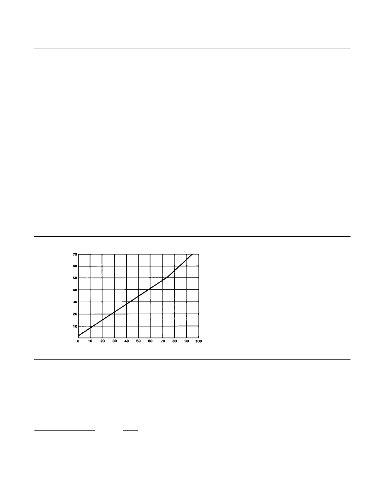
Figure 7 shows the relationship between the percent of sensor range between switching points and the proportional
band setting on the controller. The following example illustrates how to use figure 7.
Figure 7. Curve for Determining Proportional Band Setting
PROPORTIONAL BAND SETTING
A2853-1
% SENSOR RANGE BETWEEN SWITCHING POINTS
Example: The sensing element has a range of 30 psi. The lower switching point is to be set at 10 psi and the upper
switching point is to be set at 25 psi.
Proceed as follows:
D Divide the differential gap (the difference between the upper and lower switching points) by the sensing element
range. Multiply the result by 100 as shown in the following equation:
DifferentialGap
SensingElementRange
14
100 +
15psi
100 + 50%
30psi

Instruction Manual
D200157X012
4194HS IM
July 2022
D Locate the 50 percent line on figure 7. Move along this line until you intersect the curve. Read the proportional
band setting on the left hand axis. For this example, the setting is approximately 35 percent.
1. Using the curve in figure 7, determine the correct proportional band setting for the desired gap (expressed as a
percent of the input span) between the switching points.
2. Set the proportional band knob to the desired setting determined in step 1.
3. Adjust the set point to the desired upper switching point.
4. Increase the process differential pressure until the controller output signal switches from zero pressure to full
supply pressure.
5. Decrease the process differential pressure to the desired switching point at which the controller output signal
switches from full supply pressure to zero pressure.
6. Narrow or widen the proportional band slowly until the output signal switches from full supply pressure to zero
pressure.
7. Repeat steps 4 through 6 until the controller output switches at the desired points.
8. Observe the process pointer when the output switches at the upper switching point. The process pointer indication
should be within "2 percent of the set point indication.
Reverse‐Acting Controllers
The controller output signal will switch from zero pressure to full supply pressure when decreasing process differential
pressure passes the lower switching point.
The controller output signal will not return to zero pressure until increasing process differential pressure passes the
upper switching point. When adjusting the controller as described in the following steps, keep in mind that:
D Changing the set point adjustment will move both switching points equally in the direction of adjustment.
D Changing the proportional band adjustment will widen or narrow the differential gap between the two switching
points by moving the position of the upper switching point.
Figure 7 shows the relationship between the percent of sensor range between switching points and the proportional
band setting on the controller. The following example illustrates how to use figure 7.
Example: The sensing element has a range of 30 psi. The lower switching point is to be set at 10 psi and the upper
switching point is to be set at 25 psi.
Proceed as follows:
D Divide the differential gap (the difference between the upper and lower switching points) by the sensing element
range. Multiply the result by 100 as shown in the following equation:
DifferentialGap
SensingElementRange
100 +
15psi
100 + 50%
30psi
D Locate the 50 percent line on figure 7. Move along this line until you intersect the curve. Read the proportional
band setting on the left hand axis. For this example, the setting is approximately 35 percent.
1. Using the curve in figure 7, determine the correct proportional band setting for the desired gap (expressed as a
percent of the maximum input element span) between the switching points.
2. Set the proportional band knob to the desired setting determined in step 1.
3. Adjust the set point to the lower desired switching point.
4. Decrease the process differential pressure until the controller output signal switches from zero pressure to full
supply pressure.
15

4194HS IM
July 2022
Instruction Manual
D200157X012
5. Increase the process differential pressure to the desired switching point at which the controller output signal
switches from full supply pressure to zero pressure.
6. Narrow or widen the proportional band slowly until the output signal switches from full supply pressure to zero
pressure.
7. Repeat steps 4 through 6 until the controller output switches at desired points.
8. Observe the process pointer when the output switches at the lower switching point. The process pointer indication
should be within ±2 percent of the set point indication.
Principle of Operation
Overall Operation
Refer to the schematic diagram in figure 8.
Figure 8. Schematic of Fisher 4194HS Controller
SET POINT
INDICATOR
PROCESS POINTER
REMOTE SET POINT
CONNECTED HERE
INPUT ELEMENT
CONNECTED HERE
CONNECTING LINK
PROPORTIONAL
BELLOWS
(VENTED)
POSITIVE FEEDBACK
BELLOWS
PROPORTIONAL
BAND ADJUSTMENT
FEEDBACK
LINK
FEEDBACK
MOTION
DIRECT ACTION
QUADRANT
REVERSE ACTION
QUADRANT
FLAPPER
PIVOT
INPUT MOTION
FLAPPER DETAIL
OUTPUT PRESSURE
SUPPLY PRESSURE
OUTPUT PRESSURE
POSITIVE FEEDBACK PRESSURE
NOZZLE PRESSURE
B1546-2
FLAPPER
NOZZLE
SUPPLY PRESSURE
TO FINAL CONTROL
ELEMENT
RELAY
The input element is connected to the process pointer and to the flapper by connecting links. As the process
differential pressure increases (in a direct‐acting controller), the flapper moves toward the nozzle, restricting flow
through the nozzle and increasing nozzle pressure. When this occurs, relay action increases the output pressure
(delivery) of the controller. Output pressure is fed back to the positive feedback bellows. The action of this bellows is a
positive feedback action that moves the flapper closer to the nozzle, increasing nozzle pressure, which in turn,
increases the relay output. Output pressure to the final control element switches to full supply pressure.
As the process differential pressure decreases, approaching the lower switching point, the flapper moves away from
the nozzle (in a direct‐acting controller) reducing nozzle pressure. Through relay action, pressure to the positive
feedback bellows is reduced, moving the flapper farther away from the nozzle and further reducing nozzle pressure.
Output pressure to the final control element switches to zero.
16

Instruction Manual
D200157X012
4194HS IM
July 2022
The set point adjustment changes the proximity of the nozzle and flapper as does a change in process pressure except
that, when the set point is changed, the nozzle moves with respect to the flapper. The set point adjustment moves
both the upper and lower switching points.
The proportional band knob positions the nozzle on the flapper. Increasing (widening) the proportional band moves
the nozzle away from the input connection. When the proportional band adjustment moves the nozzle across the
feedback connection, the controller action changes between direct and reverse. On a direct‐acting controller,
changing the proportional band adjustment will widen or narrow the differential gap between the two switching
points. This is accomplished by changing the position of the lower switching point. On a reverse‐acting controller,
changing the proportional band adjustment will widen or narrow the differential gap between the two switching
points. This is accomplished by changing the position of the upper switching point.
Remote Set Point (suffix letter M)
The capability to adjust the controller set point from a remote location is available with all 4194HS controllers. This
option is designated by the suffix letter M in the type number.
Auto/Manual Station (suffix letter E)
Controllers with the auto/manual option (designated by the suffix letter E in the type number) have piping on the
output side of the relay as shown in figure 9. Supply pressure to the relay is also applied to the manual loader. The
manual loader, functioning as a regulator, applies pressure to one side of the plastic tube and to the auto/manual
switch. Output pressure from the relay registers on the other side of the plastic tube as well as in the auto/manual
switch.
Figure 9. Schematic of Auto/Manual Option
AUTOMATIC
POSITION
OUTPUT PRESSURE
TO FINAL CONTROL
ELEMENT
SUPPLY PRESSURE
RELAY OUTPUT PRESSURE
48A5230‐A
A2999‐1
SUPPLY PRESSURE
MANUAL LOADER OUTPUT PRESSURE
AUTO/
MANUAL
SWITCH
RELAY
MANUAL LOADER
MANUAL LOADER KNOB
PLASTIC
TUBE
METAL BALL
MANUAL POSITION
AUTO/MANUAL SWITCH
OUTPUT PRESSURE
TO FINAL CONTROL
ELEMENT
When the auto/manual switch is in the MANUAL position, the output of the manual loader is channeled through the
auto/manual switch and becomes the output of the controller. When the auto/manual switch is in the AUTO position,
the output of the relay is channeled through the switch to become the output of the controller.
17

4194HS IM
July 2022
Instruction Manual
D200157X012
Before the auto/manual switch is operated, the output of the relay must equal the output of the manual loader to
avoid bumping the process. Adjusting the set point varies the pressure on the left‐hand side of the plastic tube.
Adjusting the manual loader knob varies the pressure on the right‐hand side. When the pressures are equal, the metal
ball is centered in the tube. Pressure imbalance forces the ball to one end of the tube where it forms a seal, blocking air
flow through the tube.
Maintenance
Inspection and Maintenance
WARNING
The following maintenance procedures require taking the controller out of service. To avoid personal injury and property
damage caused by uncontrolled process pressure, observe the following before performing any maintenance procedures:
D Always wear protective clothing, gloves, and eyewear when performing any installation operations to avoid personal
injury.
D Personal injury or property damage may result from fire or explosion if natural gas is used as the supply medium and
preventative measures are not taken. Preventative measures may include, but are not limited to, one or more of the
following: Remote venting of the unit, re‐evaluating the hazardous area classification, ensuring adequate ventilation,
and the removal of any ignition sources. For information on remote venting of this controller, refer to page 8.
D Provide some temporary means of control for the process before taking the controller out of service.
D Shut off the supply pressure to the controller.
D Check with your process or safety engineer for any additional measures that must be taken to protect against process
media.
Note
Unless otherwise noted, key numbers refer to figure 26. Figures 5 and 6 show the location of adjustments and major components.
For maintenance on the indicator assembly, refer to figures 29 and 30.
Parts are subject to normal wear and must be inspected and replaced as necessary. Inspection and maintenance
frequency depends upon the severity of the service conditions. When inspection or repairs are required, disassemble
only those parts necessary to accomplish the job. Figure 10 is a maintenance guide that summarizes the information
available in the maintenance procedures.
Select the appropriate maintenance procedure and perform the numbered steps. Shut off the supply pressure and
process pressure before beginning maintenance.
The Maintenance section describes part replacement common to this type of Fisher controller. Other portions of the
maintenance procedures describe replacing the differential pressure unit, making process zero‐and‐span and flapper
alignments, and other calibration and maintenance procedures.
When maintenance procedures, including flapper alignment, have been completed, refer to the appropriate
prestartup procedure.
18
 Loading...