

Page 1

Form Number D5142
Part Number D301726X012
September 2012
ControlWave Utilities Manual
Remote Automation Solutions
Page 2

IMPORTANT! READ INSTRUCTIONS BEFORE STARTING!
Be sure that these instructions are carefully read and understood before any operation is attempted. Improper
use of this device in some applications may result in damage or injury. The user is urged to keep this book filed
in a convenient location for future reference.
These instructions may not cover all details or variations in equipment or cover every possible situation to be
met in connection with installation, operation or maintenance. Should problems arise that are not covered
sufficiently in the text, the purchaser is advised to contact Emerson Process Management, Remote Automation
Solutions for further information.
EQUIPMENT APPLICATION WARNING
The customer should note that a failure of this instrument or system, for whatever reason, may leave an
operating process without protection. Depending upon the application, this could result in possible damage to
property or injury to persons. It is suggested that the purchaser review the need for additional backup
equipment or provide alternate means of protection such as alarm devices, output limiting, fail-safe valves,
relief valves, emergency shutoffs, emergency switches, etc. If additional information is required, the purchaser
is advised to contact Remote Automation Solutions.
RETURNED EQUIPMENT WARNING
When returning any equipment to Remote Automation Solutions for repairs or evaluation, please note the
following: The party sending such materials is responsible to ensure that the materials retu rned to Remote
Automation Solutions are clean to safe levels, as such levels are defined and/or determined by applicable
federal, state and/or local law regulations or codes. Such party agrees to indemnify Remote Automation
Solutions and save Remote Automation Solutions harmless from any liability or damage which Remote
Automation Solutions may incur or suffer due to such party's failure to so act.
ELECTRICAL GROUNDING
Metal enclosures and exposed metal parts of electrical instruments must be grounded in accordance with
OSHA rules and regulations pertaining to "Design Safety Standards for Electrical Systems," 29 CFR, Part 1910,
Subpart S, dated: April 16, 1981 (OSHA rulings are in agreement with the National Electrical Code).
The grounding requirement is also applicable to mechanical or pneumatic instruments that include electrically
operated devices such as lights, switches, relays, alarms, or chart drives.
EQUIPMENT DAMAGE FROM ELECTROSTATIC DISCHARGE VOLTAGE
This product contains sensitive electronic component s that can b e damaged by exposure to an electrostatic
discharge (ESD) voltage. Depending on the magnitude and duration of the ESD, this can result in erratic
operation or complete failure of the equipment. Read supplemental document S14006 for proper care and
handling of ESD-sensitive components.
Remote Automation Solutions
Page 3

ControlWave Utilities Manual (D5142)
Contents
Chapter 1 – Introduction 1-1
1.1 What are the ControlWave Utilities? ......................................................................................... 1-1
Chapter 2 – Using ControlView 2-1
2.1 Files are downloaded to the ControlWave using ControlWave Downloader ............................ 2-1
2.2 Starting ControlView ................................................................................................................. 2-3
2.3 Establishing a Connection with the ControlWave and Uploading File(s) .................................. 2-4
Chapter 3 – Using DataView 3-1
3.1 Starting DataView ..................................................................................................................... 3-2
3.2 Using the Tool Bar within DataView .......................................................................................... 3-2
3.3 Signing on to a Node ................................................................................................................. 3-3
3.4 Printing the Entries in the Current DataView Window............................................................... 3-3
3.5 Exporting Data Entries to the Windows Clipboard ................................................................. 3-3
3.6 Conducting a Signal Search ...................................................................................................... 3-4
3.6.1 Starting the Signal Search ............................................................................................ 3-4
3.6.2 Saving Search Criteria .................................................................................................. 3-9
3.6.3 Retrieving Search Criteria ............................................................................................. 3-9
3.6.4 Altering Search Criteria ................................................................................................. 3-9
3.7 Viewing Entries in a Signal Window ........................................................................................ 3-10
3.7.1 Changing Signal Values in the Signal Window ........................................................... 3-11
3.7.2 Changing Signal Inhibit/Enable Bits in the Signal Window ......................................... 3-12
3.7.3 Changing the Floating Point Format of Data in the Signal Window ............................ 3-12
3.8 Displaying a Remote Signal List ............................................................................................. 3-13
3.8.1 Selecting a Different Remote Signal List .................................................................... 3-13
3.8.2 Changing Remote List Signal Values, Altering Inhibit/Enable Bits ............................. 3-13
3.9 Creating and Using DataView Lists ........................................................................................ 3-14
3.9.1 Creating a DataView List ............................................................................................. 3-14
3.9.2 Collecting Live Data into the DataView List ................................................................ 3-15
3.9.3 Saving the DataView List ............................................................................................ 3-15
3.9.4 Viewing a Previously Saved DataView List ................................................................. 3-15
3.10 Creating and Using Recipes ................................................................................................... 3-15
3.10.1 Creating a Recipe ....................................................................................................... 3-15
3.10.2 Saving the Recipe ....................................................................................................... 3-16
3.10.3 To View/Modify an Existing Recipe File ...................................................................... 3-17
3.10.4 To Update Signals in the Controller with the Recipe Values ...................................... 3-17
3.10.5 To Read the Current Signal Values From the Controller Into the Recipe Window ..... 3-17
3.10.6 To Cancel Unsaved Modifications to the Recipe Values ............................................ 3-17
3.10.7 Changing the Floating Point Format of Data in the Recipe Window........................... 3-17
3.11 Viewing Data for a Single Signal ............................................................................................. 3-18
3.11.1 Acknowledging an Alarm ............................................................................................. 3-19
3.12 Viewing Data Arrays ................................................................................................................ 3-19
3.12.1 Changing Values in the Data Array ............................................................................. 3-20
3.12.2 Toggling the Time/Value Format ................................................................................. 3-21
3.12.3 Keeping Column 1 Visible While Scrolling Through the Array .................................... 3-21
3.12.4 Calling Up a Different Data Array ................................................................................ 3-21
3.12.5 Changing the Floating Point Format ........................................................................... 3-21
3.13 Viewing Audit Trail Records .................................................................................................... 3-21
3.14 Viewing Archive Data Files ..................................................................................................... 3-24
Issued Sep-2012 Contents iii
Page 4

ControlWave Utilities Manual (D5142)
3.14.1 Keeping Column 1 Visible While Scrolling Through the Archive File ......................... 3-25
3.14.2 Calling Up a Different Archive File .............................................................................. 3-25
3.14.3 Changing the Floating Point Format ........................................................................... 3-25
3.14.4 Restrictions on Archive File Size ................................................................................ 3-25
Chapter 4 – Using the Downloader 4-1
4.1 Downloading to a ControlWave-series Node: ........................................................................... 4-1
4.1.1 Before You Begin .......................................................................................................... 4-1
4.1.2 Starting the ControlWave Downloader.......................................................................... 4-4
4.1.3 Using the ControlWave Downloader ............................................................................. 4-4
Chapter 5 – Using the Flash Configuration utility 5-1
5.1 Starting the Flash Configuration Utility ...................................................................................... 5-1
5.2 Flash Configuration Utility Buttons ............................................................................................ 5-4
5.3 Forcing a Reboot of the ControlWave ....................................................................................... 5-6
5.4 Flash Configuration Utility Tabs ................................................................................................ 5-7
5.5 Soft Switches ............................................................................................................................ 5-8
5.6 Ports .......................................................................................................................................... 5-9
5.6.1 IP Network Security Protocols (CHAP and PAP) Used on PPP Links ....................... 5-14
5.6.2 Challenge Handshaking Authentication Protocol (CHAP) .......................................... 5-15
5.6.3 Password Authentication Protocol (PAP) ................................................................... 5-18
5.7 IP Parameters ......................................................................................................................... 5-25
5.8 Application Parameters ........................................................................................................... 5-30
5.9 Archive .................................................................................................................................... 5-32
5.10 Audit ........................................................................................................................................ 5-37
5.11 IP Routes ................................................................................................................................ 5-40
5.12 Security ................................................................................................................................... 5-42
Chapter 6 – Using the Communication Statistics Tool 6-1
6.1 Accessing the Remote Communication Statistics Tool ............................................................ 6-2
6.2 Signing On to a Node ................................................................................................................ 6-3
6.3 Crash Block Statistics Window ................................................................................................. 6-3
6.4 Port Summary Statistics Window .............................................................................................. 6-5
Port Detail Statistics Window.................................................................................................... 6-6
Master/Expanded Addressing Master Port Statistics ............................................................... 6-6
Slave, Pseudo-Slave, Pseudo-Slave with Alarms, Serial CFE or VSAT Slave Port Statistics 6-7
Custom Port Statistics .............................................................................................................. 6-8
Internet Protocol (IP) Port Statistics ......................................................................................... 6-8
6.5 Version Information Window ..................................................................................................... 6-9
6.6 Node Routing Table Window .................................................................................................. 6-11
6.7 Internet Protocol (IP) Statistics Window .................................................................................. 6-12
IP Statistics Decription ............................................................................................................ 6-13
ICMP Statistics Description .................................................................................................... 6-14
UDP Statistics Description ...................................................................................................... 6-15
IBP Statistics Description ....................................................................................................... 6-16
6.8 Printing the Entries in the Current Window ............................................................................. 6-17
6.9 Exporting Data Entries to the Windows™ Clipboard ................................................................ 6-17
Chapter 7 – Using the System Firmware Downloader 7-1
7.1 What is System Firmware? ....................................................................................................... 7-1
7.2 Requirements for Using the System Firmware Downloader ..................................................... 7-2
7.3 Starting the System Firmware Downloader .............................................................................. 7-3
7.4 Downloading System Firmware to a Single Controller ............................................................. 7-4
7.5 Setting Application Parameters for the System Firmware Downloader .................................... 7-5
iv Contents Issued Sep-2012
Page 5

ControlWave Utilities Manual (D5142)
Security Tab .............................................................................................................................. 7-5
Batch Mode Tab ....................................................................................................................... 7-6
7.6 Using PROM Reporter to see which Firmware is Loaded in an RTU ....................................... 7-6
Issued Sep-2012 Contents v
Page 6

This page is intentionally left blank
Page 7

ControlWave Utilities Manual (D5142)
Chapter 1 – Introduction
This manual provides instructions for using ControlWave utilities
software.
In This Chapter
1.1 What are the ControlWave Utilities? ................................................ 1-1
1.1 What are the ControlWave Utilities?
OpenEnterprise™ Field Tools includes a set of utility programs used
with ControlWave controllers. Most are launched from within
TechView. These utilities include:
ControlView File Viewer – This utility retrieves certain file types
from the ControlWave’s flash memory, and launches associated
applications so you can view them on the PC, such as HTML files.
ControlWave Downloader – This utility takes the ControlWave
project you create with ControlWave Designer and downloads it into
the ControlWave controller.
DataView – This utility collects various kinds of data from the
ControlWave for you to view on screen (variable values, lists,
archives, arrays).
Flash Configuration utility – This utility lets you update
configuration parameters in the ControlWave’s flash memory for
things like communication ports, IP addresses, memory, and so on.
Remote Communication Statistics utility – This utility lets you view
statistics regarding the “health” of ControlWave communications.
System Firmware Downloader – This utility lets you perform an
upgrade to the system firmware in the ControlWave.
Besides these utilities, there are other software programs for
ControlWave devices accessible in Field Tools; for information on
these, consult the sources listed in Table 1-1.
Table 1-1 Finding information about other ControlWave software
included within Field Tools
Software Description See these sources of information
Used to create control
strategy
ControlWave Designer
Debug_Info Tools
Issued Sep-2012 Introduction 1-1
(ControlWave project)
that executes inside
the ControlWave
controller.
Provides certain
debug information;
Getting Started with ControlWave
Designer (D5085)
ControlWave Designer
Programmer’s Handbook (D5125)
Online help in ControlWave Designer
ControlWave Designer
Programmer’s Handbook (D5125) –
Page 8
ControlWave Utilities Manual (D5142)
Software Description See these sources of information
Diagnostics utility
Reset ControlWave utility
TechView
Web_BSI
primarily used by
technical support
personnel.
Runs basic diagnostic
routines on the
ControlWave
hardware.
Allows you to power
cycle the
ControlWave.
Used to launch web
pages, custom
applications, and
configuration tools.
A set of HTML pages
and web controls
specifically geared
towards
communication with
and data collection
from ControlWave
devices.
Appendix B
Diagnostics Manual (D4041A)
ControlWave Designer
Programmer’s Handbook (D5125)
TechView User’s Guide (D5131)
Web_BSI Manual (D5087)
Notes:
Some of these utilities (Remote Communication Statistics,
Debug_Info, Diagnostics, Reset ControlWave) are not accessible
from menus by default because they are typically used by advanced
users.
If you want to add one or more of these to the menu, follow the
instructions for adding menu items to initialization files in Appendix
A of the TechView User’s Guide (D5131).
1-2 Introduction Issued Sep-2012
Page 9

ControlWave Utilities Manual (D5142)
Chapter 2 – Using ControlView
The ControlWave-series of process automation controllers can store
user-created files in FLASH memory in a folder called “ControlView.”
These could include HTML files, ZIP files, etc. The underlying file
transfer between the ControlWave and the PC is accomplished using the
industry standard File Transfer Protocol (FTP).
The ControlView utility allows you to retrieve these files from the
ControlWave, copy them to the PC, and launch the associated
application program for those files.
Once you connect to the ControlWave, ControlView displays the
contents of the ControlView folder on the RTU so you can select the
desired file and ControlView automatically uploads the file and
launches the Windows™ application associated with that file type.
For example, if you have created HTML pages for displaying signal
values from the ControlWave (using Web_BSI’s ActiveX controls),
ControlView allows you to connect to the ControlWave, upload the
HTML files from the ControlView folder to your PC (using FTP), and
launch Internet Explorer to allow you to view the HTML pages with
their associated data from the ControlWave.
In This Chapter
2.1 Files are downloaded to the ControlWave using ControlWave
Downloader ...................................................................................... 2-1
2.2 Starting ControlView ........................................................................ 2-3
2.3 Establishing a Connection with the ControlWave and Uploading File(s)
......................................................................................................... 2-4
2.1 Files are downloaded to the ControlWave using ControlWave
Downloader
Files are downloaded to the ControlWave’s FLASH memory using the
ControlWave Downloader included with Field Tools. You must select
the “Download User Files” option in the Downloader, prior to starting
the download.
The Downloader takes all files in the directory defined by the “User
Files Path”, and downloads them to the ControlWave.
Issued Sep-2012 ControlView 2-1
Page 10

ControlWave Utilities Manual (D5142)
Check “Download User Files” when you
download files to the ControlView file area
of the ControlWave’s flash memory.
Figure 2-1. Downloading Files to the ControlWave
The “User Files Path” should follow the format shown below:
\OpenBSI\Downloads\project_name\ControlView
Where:
project_name is the basename of the ControlWave project. The folder
containing the files to be downloaded must be a subdirectory of projectname called ControlView.
So, for example, if the ControlWave project name is STATION3, then
the folder containing the files to be downloaded to FLASH should be
called:
\OpenBSI\Downloads\STATION3\ControlView
IMPORTANT:
If the files you are downloading are to be compressed into a zip file, you
must include a STARTUP.INI file within the zip file, which identifies
which application should be launched when the files are unzipped. This
file takes the format:
[STARTUP]
File = xxxxx.yyy
Program = program_name
Where
xxxxx.yyy is the name of one of the zipped files
2-2 ControlView Issued Sep-2012
Page 11

ControlWave Utilities Manual (D5142)
program_name is the name of the program ControlView should
launch once the zipped file is unzipped. If the
directory containing the program is not part of the
standard Windows™ PATH statement, you must
enter the entire path and filename of the program
executable here.
Example STARTUP.INI File:
[STARTUP]
File=mymenu.htm
Program=iexplore
2.2 Starting ControlView
1. If not already done, use Field Tools to establish a communication
connection (either serial or IP) with the ControlWave controller and
launch TechView. (For information on doing this, see Chapter 3 of
the OpenEnterprise™ Field Tools Quick Setup Guide (D5141) or
consult the online help in Field Tools.
2. Right-click on the icon for the controller and choose ControlView
from the pop-up menu.
Issued Sep-2012 ControlView 2-3
Page 12
ControlWave Utilities Manual (D5142)
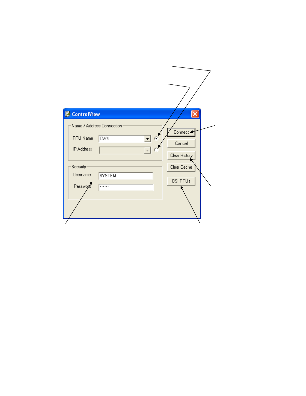
2.3 Establishing a Connection with the ControlWave and Uploading
File(s)
Select this button to enter the IP address
-orSelect this button to use the RTU name
You cannot enter both the IP address and
the RTU name
Click “Connect” to
establish the
connection and display
the files available for
upload.
You must provide a valid
username / password combination
to access the ControlWave.
The list controls allow you
to call up previous
entries. To erase the
previous entries, click
“Clear History.”
Not applicable in Field
1.
Tools.
Figure 2-2. ControlView
1. Field Tools automatically fills in the node name. If you’d rather
specify an IP address select the button to the right of the IP Address
field, then enter the ControlWave’s IP address in the IP Address
field (or use the list control to select it if it appears in the history list
of IP addresses).
2. Enter a valid Username / Password combination for this
ControlWave.
3. Click Connect and ControlView displays a list of files available for
upload from the ControlWave.
2-4 ControlView Issued Sep-2012
Page 13

ControlWave Utilities Manual (D5142)
4. From the list box in the Select File to View dialog box, select the
file you want to view and click OK. ControlView uploads that file
to the PC and launches its application. (Note: If there is only one file
in the ControlView area of FLASH available for uploading, you
don’t have to select it; ControlView uploads it automatically and
launches its associated application.)
Select which file you want
to upload and click OK.
Figure 2-3. Selecting File to Upload
Note: If the file you upload is a zipped (compressed) file, ControlView
automically uncompresses the file; the application it launches
depends on entries in the STARTUP.INI file.
Issued Sep-2012 ControlView 2-5
Page 14

This page is intentionally left blank
Page 15

ControlWave Utilities Manual (D5142)
Chapter 3 – Using DataView
DataView allows you to collect several types of data from a
ControlWave series controller, including signal data, signal lists, archive
data, array values, and audit trail alarm/event information. In addition, it
allows you to search for signals based on various criteria, and also
allows you to send recipes (lists of signal values) to the controller.
In This Chapter
3.1 Starting DataView ............................................................................ 3-2
3.2 Using the Tool Bar within DataView ................................................ 3-2
3.3 Signing on to a Node ....................................................................... 3-3
3.4 Printing the Entries in the Current DataView Window ..................... 3-3
3.5 Exporting Data Entries to the Windows Clipboard ....................... 3-3
3.6 Conducting a Signal Search ............................................................ 3-4
3.6.1 Starting the Signal Search .................................................... 3-4
3.6.2 Saving Search Criteria ......................................................... 3-9
3.6.3 Retrieving Search Criteria .................................................... 3-9
3.6.4 Altering Search Criteria ........................................................ 3-9
3.7 Viewing Entries in a Signal Window .............................................. 3-10
3.7.1 Changing Signal Values in the Signal Window .................. 3-11
3.7.2 Changing Signal Inhibit/Enable Bits in the Signal Window 3-12
3.7.3 Changing Floating Point Format of Data in Signal Window3-12
3.8 Displaying a Remote Signal List .................................................... 3-13
3.8.1 Selecting a Different Remote Signal List ............................ 3-13
3.8.2 Changing Remote List Signal Values ................................. 3-13
3.9 Creating and Using DataView Lists ............................................... 3-14
3.9.1 Creating a DataView List .................................................... 3-14
3.9.2 Collecting Live Data into the DataView List ....................... 3-15
3.9.3 Saving the DataView List ................................................... 3-15
3.9.4 Viewing a Previously Saved DataView List ........................ 3-15
3.10 Creating and Using Recipes .......................................................... 3-15
3.10.1 Creating a Recipe ............................................................... 3-15
3.10.2 Saving the Recipe .............................................................. 3-16
3.10.3 To View/Modify an Existing Recipe File ............................. 3-17
3.10.4 To Update Signals in the Controller with the Recipe Values 3-17
3.10.5 To Read the Current Signal Values From the Controller ... 3-17
3.10.6 To Cancel Unsaved Modifications to the Recipe Values ... 3-17
3.10.7 Changing the Floating Point Format of Data ...................... 3-17
3.11 Viewing Data for a Single Signal ................................................... 3-18
3.11.1 Acknowledging an Alarm .................................................... 3-19
3.12 Viewing Data Arrays ...................................................................... 3-19
3.12.1 Changing Values in the Data Array .................................... 3-20
3.12.2 Toggling the Time/Value Format ........................................ 3-21
3.12.3 Keeping Column 1 Visible While Scrolling Through the Array3-21
3.12.4 Calling Up a Different Data Array ....................................... 3-21
3.12.5 Changing the Floating Point Format .................................. 3-21
3.13 Viewing Audit Trail Records ........................................................... 3-21
3.14 Viewing Archive Data Files ............................................................ 3-24
3.14.1 Keeping Column 1 Visible .................................................. 3-25
3.14.2 Calling Up a Different Archive File ..................................... 3-25
3.14.3 Changing the Floating Point Format .................................. 3-25
3.14.4 Restrictions on Archive File Size ........................................ 3-25
Issued Sep-2012 DataView 3-1
Page 16
ControlWave Utilities Manual (D5142)
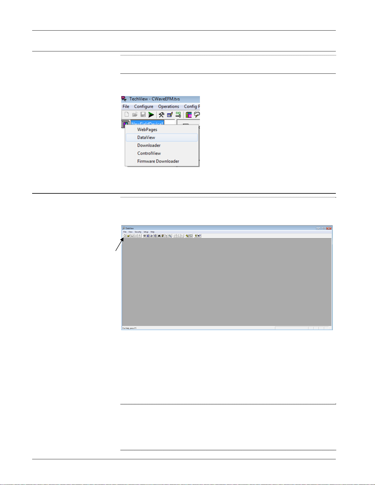
3.1 Starting DataView
Note: Before starting DataView, you must establish communications
with the controller using Field Tools, then launch TechView.
Right click on the RTU name in TechView then choose DataView from
the pop-up menu.
3.2 Using the Tool Bar within DataView
The DataView window includes a tool bar which provides you easy
access to DataView's features and functions, and serves as an alternative
to using the menu bar and pull down menus.
Toolbar
Figure 3-1. DataView
If you position the mouse cursor over any tool bar icon you can see a
label which identifies the icon's function. (Note: The number and
function of active icons in the tool bar varies depending upon which
DataView feature currently runs in the window.) A single click on the
icon activates its feature. See the pages which follow for a description of
the various DataView features.
Notes:
You can run multiple DataView functions simultaneously in
separate windows, if sufficient memory is available.
If sufficient memory is available, you can run multiple copies of
DataView simultaneously.
3-2 DataView Issued Sep-2012
Page 17

ControlWave Utilities Manual (D5142)
3.3 Signing on to a Node
When invoked from within Field Tools, DataView automatically uses
the Field Tools RTU credentials; so you do not need to sign on.
The Automatic Sign-on feature does not apply when launching
DataView through Field Tools.
3.4 Printing the Entries in the Current DataView Window
You can print the textual data displayed in the various types of
DataView Windows on a printer.
Notes:
Before attempting to print, you must configure a printer and connect
it to this workstation, either directly, or through a network. To
access the Windows Print Setup dialog box, click File > Print
Setup.
The types of DataView windows which hold printable data include
Signal windows (which are used to display Signal Searches,
DataView Lists, or Remote Lists) as well as other types of windows
such as Audit Trail windows, Archive windows, and Array
windows. All of these types of windows will be discussed later in
this manual.
To preview the data you want to print, click File>Print Preview from
the menu bar.
To print the entries (data) in the current DataView window, click the
printer icon, shown above, or click File>Print. The Windows Print
dialog box opens. See your Windows™ documentation for further
information.
3.5 Exporting Data Entries to the Windows Clipboard
As an alternative to sending data to the printer, described above, you
can copy DataView window entries as text to the Windows Clipboard.
From the Clipboard, you can export the data to other Windows
applications such as spreadsheets or word processors. DataView formats
its entries specifically for use in Microsoft Excel.
To copy entries in the current DataView window to the Windows
Clipboard, click File>Copy to Clipboard.
See your Windows documentation for more information on using the
Clipboard.
Issued Sep-2012 DataView 3-3
Page 18

ControlWave Utilities Manual (D5142)
3.6 Conducting a Signal Search
A signal search allows you to search for all signals (variables) which
share one or more common characteristics. For example, you can define
the search criteria to be all signals which share the same signal
extension and are control-inhibited. Or you could search for all signals
currently in the high-high alarm state. The following is a list of valid
signal search criteria:
Signal base name, extension, or attribute (ControlWave configured
to use ACCOL names)
Variable/function block instance name
String Search
Current alarm state (logical alarm, high, high-high, low, low-low)
Inhibit/enable bit status (alarm inhibit/enable, control inhibit/enable,
manual inhibit/enable)
Questionable data bit status
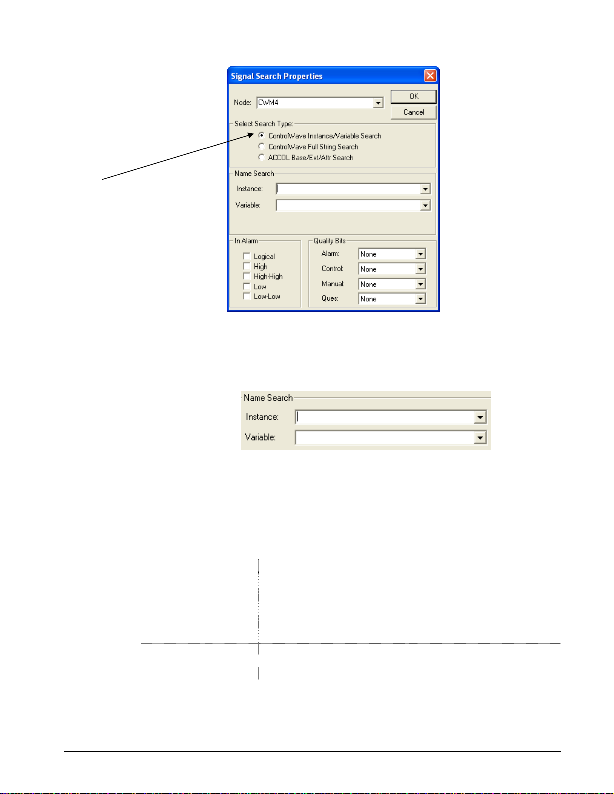
3.6.1 Starting the Signal Search
To start a Signal Search, click on the Signal Search tool bar icon (shown
at left), or click File > New, and then click Signal Search in the New
list box. Either method opens the Signal Search Properties dialog box.
Field Tools automatically populates the Node name field. Use the other
fields to specify the parameters of your search.
Notes:
To see all variables in the project (both global and local variables
marked as “PDD”) you can leave all the selection fields blank.
Some of the searches support wildcard characters. Wildcard
characters allow you to search for items for which you don’t know
the exact name, or for which there may be several possible matches.
There are two wildcard characters supported, “*” and “?”
The * indicates that DataView should automatically consider any
characters in the position where the * appears as valid matches for
this search. For example, if you search for “COMP*,” items like
“COMP4,” “COMPRESSOR” and “COMPORT” are all considered
valid matches.
The ? indicates that DataView should accept the substitution of any
one single character for the question mark as a valid match for this
search. For example, if you search for “PUMP?RUN” then
“PUMP1RUN,” “PUMP2RUN” or “PUMPNRUN” are all
considered valid matches.
3-4 DataView Issued Sep-2012
Page 19
ControlWave Utilities Manual (D5142)
Choose the type of
search you want to
conduct.
Figure 3-2. Signal Search Properties dialog box
Instance/Variable
Search Mode:
For ControlWave controllers you can search based on the POU
Instance name(s), and/or the Variable name. You can use
wildcards in either of these fields.
The same variable can have multiple instance names associated
with it, for example, an instance for the program, followed by the
instance for a function block, etc. A period “.” character follows
each instance therefore an instance name is always to the left of
the last period. DataView considers the portion to the right of the
last period to be the variable name. The signal search can only
find variables which you previously marked as “PDD.”
Field Description
Instance
Variable
You can enter up to 32 characters in the Instance name portion. If
you do NOT use wildcard characters, the instance name must match
exactly to be considered a valid match. For global variables the POU
instance name must be “@GV.” If you leave the Instance field blank,
DataView considers any instance name to be valid, and it only uses
the Variable field in the search.
You can enter up to 32 characters in the Variable name portion. If you
do NOT use wildcard characters, the variable name must match
exactly to be considered a vali d mat ch. If y ou le ave the Variabl e field
blank, DataView only uses the Instance field in the search
Some Examples:
Issued Sep-2012 DataView 3-5
Page 20

ControlWave Utilities Manual (D5142)
e
Let’s say you have a set of variables with the following names (Figure
3-3).
instance
name
multiple
instance
names
@GV.PRESSURE_READING
@GV.MYFB.STATION1_FLOW
@GV.MYFB.STATION2_FLOW
@GV.MYFB.STATION3_FLOW
@GV.MYFB.STATION4_FLOW
@GV.MYFB2.STATION1_FLOW
@GV.MYFB2.STATION2_FLOW
@GV.MYFB2.STATION3_FLOW
@GV.MYFB2.STATION4_FLOW
PROG1.TEMP_HIGH
PROG1.TEMP_LOW
PROG1.TEMP_CURRENT
instance
name
variable name
variable nam
variable name
Figure 3-3. Sample Set of Variables
Table 3-1 lists some resulting matches for searches based on this set of
variables:
Table 3-1. Sample Search Results – Instance / Variable
If you enter
this in the
Instance field
* STATION1* @GV.MYFB.STATION1_FLOW
leave blank
@GV.MYFB* STATION2* @GV.MYFB.STATION2_FLOW
PROG TEMP*
PROG*
And you enter this in
the Variable field
TEMP* PROG1.TEMP_HIGH
leave blank
DataView returns the
following variables from the
set of variables shown in
Figure 3-3.
@GV.MYFB2.STATION1_FLOW
PROG1.TEMP_LOW
PROG1.TEMP_CURRENT
@GV.MYFB2.STATION2_FLOW
No matches; because no wildcard
following ‘PROG’.
PROG1.TEMP_HIGH
PROG1.TEMP_LOW
PROG1.TEMP_CURRENT
@GV.MYFB2
*.* STATION3* @GV.MYFB.STATION3_FLOW
3-6 DataView Issued Sep-2012
leave blank
@GV.MYFB2.STATION1_FLOW
@GV.MYFB2.STATION2_FLOW
@GV.MYFB2.STATION3_FLOW
@GV.MYFB2.STATION4_FLOW
@GV.MYFB2.STATION3_FLOW
Page 21

ControlWave Utilities Manual (D5142)
If you enter
this in the
Instance field
*
*.*
And you enter this in
the Variable field
leave blank
leave blank
DataView returns the
following variables from the
set of variables shown in
Figure 3-3.
@GV.PRESSURE_READING
@GV.MYFB.STATION1_FLOW
@GV.MYFB.STATION2_FLOW
@GV.MYFB.STATION3_FLOW
@GV.MYFB.STATION4_FLOW
@GV.MYFB2.STATION1_FLOW
@GV.MYFB2.STATION2_FLOW
@GV.MYFB2.STATION3_FLOW
@GV.MYFB2.STATION4_FLOW
PROG1.TEMP_HIGH
PROG1.TEMP_LOW
PROG1.TEMP_CURRENT
@GV.MYFB.STATION1_FLOW
@GV.MYFB.STATION2_FLOW
@GV.MYFB.STATION3_FLOW
@GV.MYFB.STATION4_FLOW
@GV.MYFB2.STATION1_FLOW
@GV.MYFB2.STATION2_FLOW
@GV.MYFB2.STATION3_FLOW
@GV.MYFB2.STATION4_FLOW
*.MYFB2
leave blank
or
*
*.MYFB2* STATION2_FL?W @GV.MYFB2.STATION2_FLOW
PROG?
@GV.MYFB?
leave blank
STATION?_FLOW @GV.MYFB.STATION1_FLOW
leave blank
leave blank
@GV.MYFB2.STATION1_FLOW
@GV.MYFB2.STATION2_FLOW
@GV.MYFB2.STATION3_FLOW
@GV.MYFB2.STATION4_FLOW
@GV.MYFB.STATION2_FLOW
@GV.MYFB.STATION3_FLOW
@GV.MYFB.STATION4_FLOW
@GV.MYFB2.STATION1_FLOW
@GV.MYFB2.STATION2_FLOW
@GV.MYFB2.STATION3_FLOW
@GV.MYFB2.STATION4_FLOW
PROG1.TEMP_HIGH
PROG1.TEMP_LOW
PROG1.TEMP_CURRENT
@GV.MYFB.STATION1_FLOW
@GV.MYFB.STATION2_FLOW
@GV.MYFB.STATION3_FLOW
@GV.MYFB.STATION4_FLOW
@GV.MYFB2.STATION1_FLOW
@GV.MYFB2.STATION2_FLOW
@GV.MYFB2.STATION3_FLOW
@GV.MYFB2.STATION4_FLOW
Issued Sep-2012 DataView 3-7
Page 22
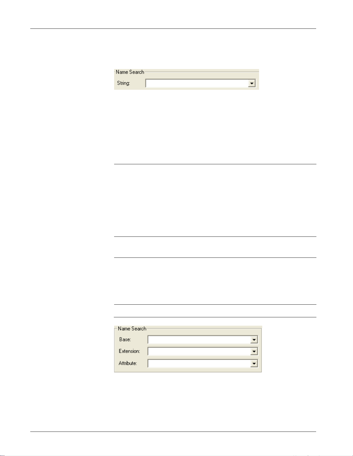
ControlWave Utilities Manual (D5142)
ControlWave Full
String Search
Mode:
For this search, you can enter a string that is in either the instance name
or variable name.
The search string you enter can include wildcards to establish a pattern
for DataView to match.
Table 3-2 shows some examples, using the same set of variables from
Figure 3-3.
Table 3-2. Sample Search Results – String
If you enter
this in the
String field
DataView returns the following variables from the set
of variables shown in Figure 3-3.
*STATION?_F* @GV.MYFB.STATION1_FLOW
@GV.MYFB.STATION2_FLOW
@GV.MYFB.STATION3_FLOW
@GV.MYFB.STATION4_FLOW
@GV.MYFB2.STATION1_FLOW
@GV.MYFB2.STATION2_FLOW
@GV.MYFB2.STATION3_FLOW
@GV.MYFB2.STATION4_FLOW
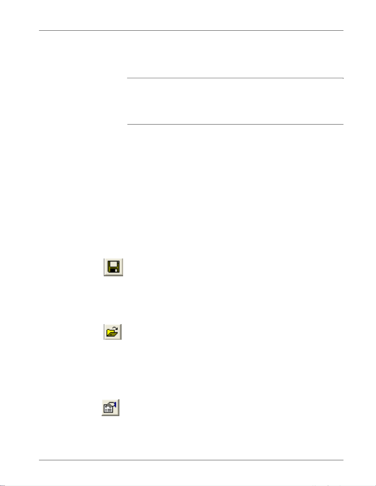
ACCOL Base,
Extension, and
Attribute Search
Mode
*MYFB?.STA
TION2*
@GV.MYFB.STATION2_FLOW
@GV.MYFB2.STATION2_FLOW
*1* @GV.MYFB.STATION1_FLOW
@GV.MYFB2.STATION1_FLOW
PROG1.TEMP_HIGH
PROG1.TEMP_LOW
PROG1.TEMP_CURRENT
@GV.P* @GV.PRESSURE_READING
If DataView communicates with a ControlWave and you set the
_USE_ACCOL_NAME system variable in your ControlWave project to
TRUE, you can use the Base, Extension and Attribute fields. To work
properly in this case, though, the signal names you search for must fit
the ACCOL II signal naming convention, i.e. no more than eight alphanumeric characters for the base, no more than six for the extension, and
3-8 DataView Issued Sep-2012
Page 23
ControlWave Utilities Manual (D5142)
no more than four for the attribute. In addition, characters such as the at
sign “@” cannot be included. The underscore “_” may work if it’s at the
end of the search parameter, but it will not work at the beginning of the
search parameter.
Notes:
Do not enter wildcard characters in this mode.
You must search using the complete, Base, Extension, or Attribute,
not part of it. For example, to search for an attribute of “FLOW,”
you must enter “FLOW,” not “FLO,” “FL,” or “F.”
In Alarm and
Quality Bits
The In Alarm check boxes let you select signals which share the same
alarm status.
The Quality Bits area list boxes allow you to select signals based on the
inhibit/enable status for each alarm, control, or manual inhibit/enable bit.
You can also select based on the Questionable data status.
Select the desired search criteria, and click OK to execute the search. A
signal window opens to display all signals/variables which share the
selected characteristics. See Viewing Entries in the Signal Window for
information on using the entries in this window to change signal values,
or to alter inhibit / enable bits. See Viewing Data for a Single Signal for
information on viewing more detailed signal information. Note: The
window can only display the first 5000 signals found.
3.6.2 Saving Search Criteria
Once the Signal Window opens you can save its associated signal search
criteria in a file by clicking on the icon, shown at left, or you can click
File>Save As. Enter a name for the search criteria file, with an extension
of .SCH. You can save subsequent modifications to the SCH file if you
click on the same icon, or click File>Save.
3.6.3 Retrieving Search Criteria
DataView lists the names of the last four files viewed (of all file types)
in the File pull down menu. If the search criteria (.SCH) file you want to
view appears in the menu, you can open the file by simply clicking on
the file name. To call up any other search criteria (SCH) file, click the
icon, shown at left, or click File>Open. Select the desired SCH file from
the windows Open File dialog box, and click the Open button.
3.6.4 Altering Search Criteria
Once the Signal Window opens, you can change the search criteria by
Issued Sep-2012 DataView 3-9
clicking on the Properties tool bar icon, shown at left, or by clicking on
Format>Properties. The Signal Search Properties dialog box re-opens
to allow you to define new search criteria.
Page 24
ControlWave Utilities Manual (D5142)
ON/O
t)
tes to controller
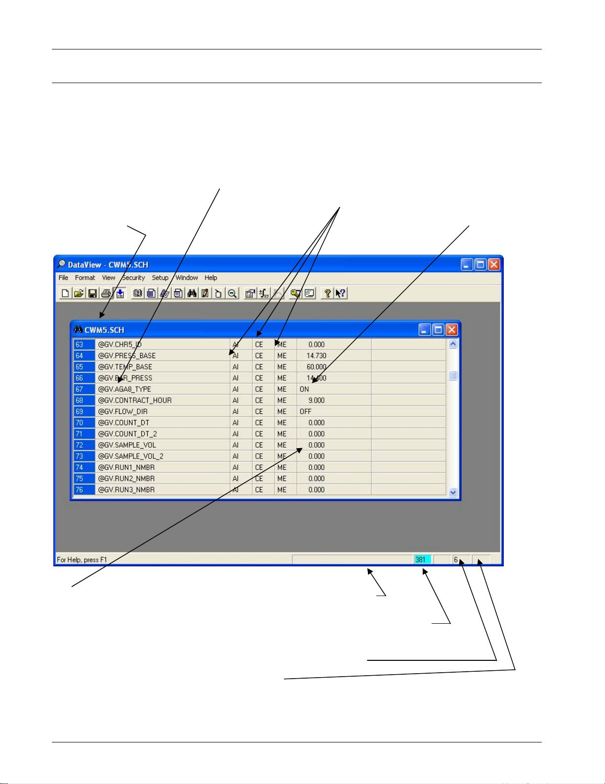
3.7 Viewing Entries in a Signal Window
DataView displays Remote Signal Lists, DataView Lists, and Signal
Searches in a signal window. You can view detailed signal information,
change signal values, or alter the inhibit/enable bits by clicking on those
fields for a particular entry in the signal window. Use the scroll bar to
view any entries not currently visible on the screen. The figure below
summarizes the elements in a signal window.
Signal Name (click
File name for the
signal search
on to get more
detailed info)
Inhibit/Enable status
bits (click on them
to change status)
Units Text (or
FF tex
Signal Value
(click on the
value to
change it)
(If value appears in red, signal
is “in-alarm;” if “!” appears,
alarm has not been
acknowledged by the central
computer (HMI/SCADA
package)
Number of pending
wri
Error/Status
Message area
Number of entries collected
Current
operator
security level
Figure 3- 4. Signal Window
3-10 DataView Issued Sep-2012
Page 25
ControlWave Utilities Manual (D5142)
Notes:
For information on viewing detailed signal information, see Viewing
Data for a Single Signal, later in this section.
For Remote Signal Lists, and Signal Searches, the number of entries
which have been collected are displayed at the bottom of the
window in the status bar. If this value appears with a cyan (light
blue) background, then there are additional entries in the controller
which have not yet been collected
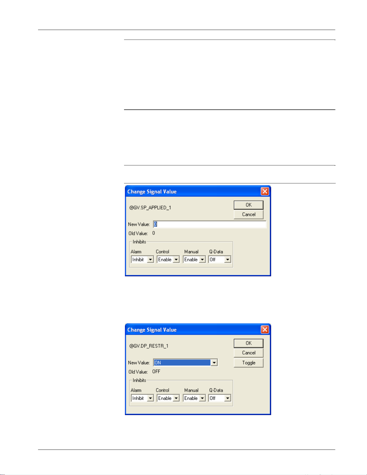
3.7.1 Changing Signal Values in the Signal Window
Click on the signal value you want to change. The Change Signal Value
dialog box opens to allow you to change the signal value, as well as the
manual, control, and alarm inhibit/enable bits, and the questionable data
bit.
Note To change a signal value, you must manually enable the signal (if
it isn’t already).
Figure 3-5. Change Signal Value – Analog
If the signal you want to change is a logical signal, you can either use
the list box to select the new state, or you can simply click on the
Toggle push button.
Figure 3-6. Change Signal Value – Logical
Issued Sep-2012 DataView 3-11
Page 26
ControlWave Utilities Manual (D5142)
Note: The questionable data bit for logical signals can only be changed
through this dialog box; there is no automatic questionable
checking from the discrete I/O boards.
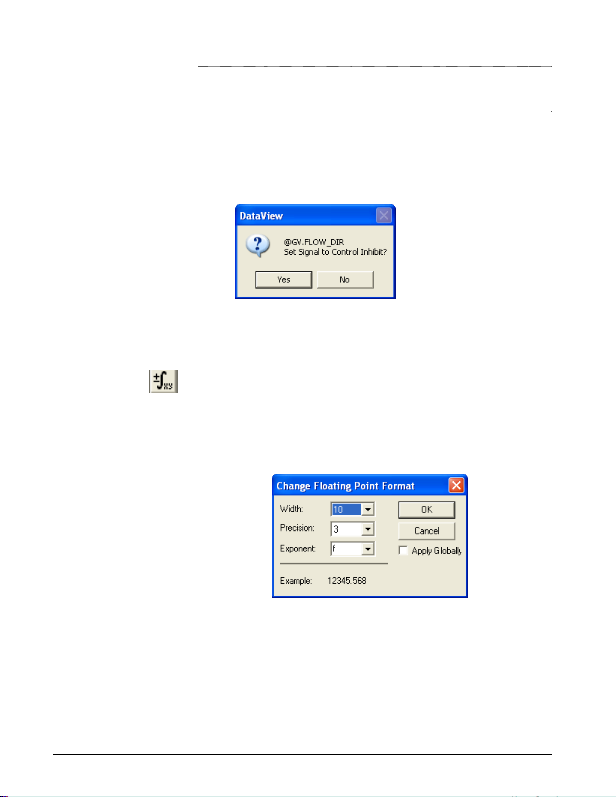
3.7.2 Changing Signal Inhibit/Enable Bits in the Signal Window
Click the inhibit/enable bit you would like to change. DataView
prompts you to confirm that you want to change the inhibit/enable
status. You can also change the inhibit/enable status using the Change
Signal Value dialog box, above.
Figure 3-7. Change Inhibit/Enable Status
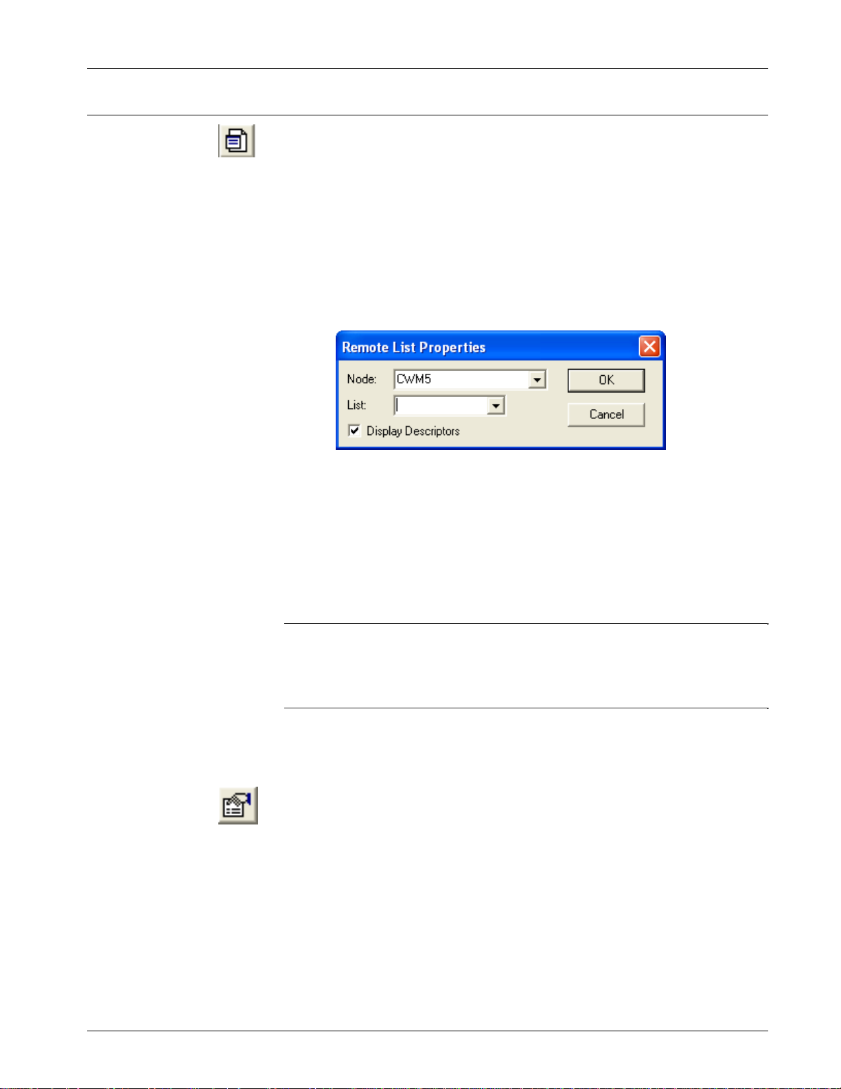
3.7.3 Changing the Floating Point Format of Data in the Signal
Window
The Signal Window (and certain other types of windows) displays
analog values according to a default floating point format. To alter this
default format, click on the Change Floating Point Format tool bar icon
(shown at left) or click Format > Floating Point. The Change Floating
Point Format dialog box opens. Use the Width list box to specify the
total number of characters in the field (including the decimal point) used
to display a floating point number.
Figure 3-8. Change Floating Point Format dialog box
Use the Precision list box to choose the number of places to the right of
the decimal point which the window should display.
Use the Exponent list box to choose floating point format f, exponential
notation e or choose g to have DataView choose the “best fit” format.
If you want the floating point format defined here to apply throughout
the DataView windows, check the Apply Globally check box.
3-12 DataView Issued Sep-2012
Page 27
ControlWave Utilities Manual (D5142)
3.8 Displaying a Remote Signal List
The Signal Window (and certain other types of windows) displays
analog values according to a default floating point format. To alter this
default format, click on the Change Floating Point Format tool bar icon
(shown at left) or click Format Floating Point. The Change Floating
Point Format dialog box opens. Use the Width list box to specify the
total number of characters in the field (including the decimal point) used
to display a floating point number.
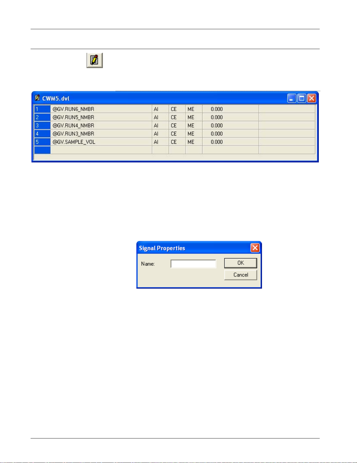
To view a signal list in the remote process controller, click the Remote
List tool bar icon, shown at left or click File>New. Choose Remote
List from the New list box.
Figure 3-9. Remote List Properties dialog box
You can use the List list box to see which signal lists exist in the
controller, and then select a list from it, or you can just type the list
number in the box; then click OK. A signal window opens containing
the signal list entries.
If you check Display Descriptors, signal descriptive text, if it exists,
appears in the signal window instead of the signal name.
Notes:
DataView cannot display more than 10,000 signals from a particular
list.
DataView cannot display lists numbered higher than 255.
3.8.1 Selecting a Different Remote Signal List
Once the Signal Window opens, you can recall the Remote List
Properties dialog box to call up a different list by clicking the Properties
icon, shown at left, or by clicking Format>Properties.
3.8.2 Changing Remote List Signal Values, Altering Inhibit/Enable
Bits
See Section 3.7 for information on using the entries in this window to
change signal values, or to alter inhibit/enable bits. See Viewing Data
for a Single Signal (later in this manual) for information on viewing
more detailed signal information.
Issued Sep-2012 DataView 3-13
Page 28
ControlWave Utilities Manual (D5142)
3.9 Creating and Using DataView Lists
A DataView List is a file, stored on the PC, that contains the names of
signals, from a single controller, from which you would like to collect
data. You can open the DataView list file in DataView to collect and
display data for the designated signals.
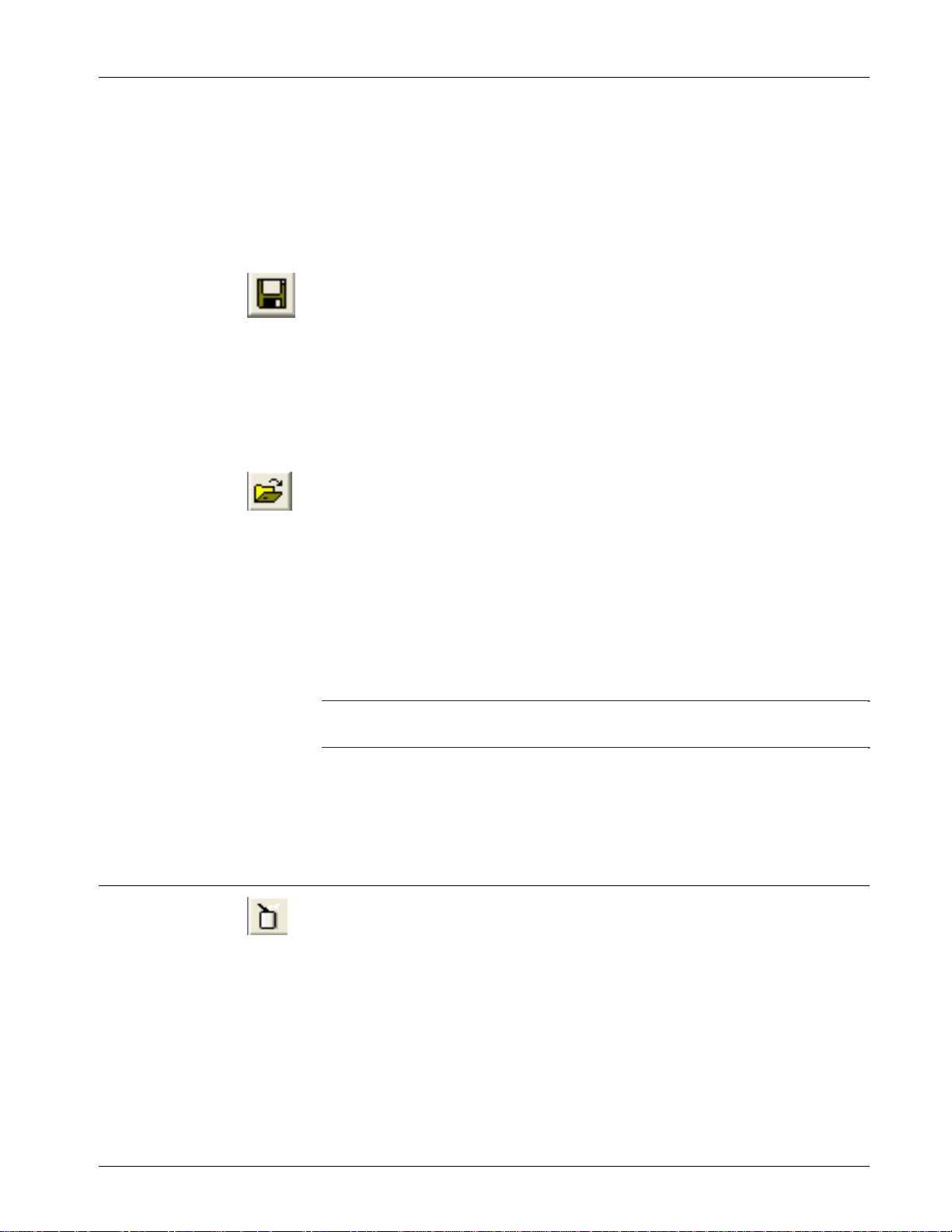
Figure 3-10. DataView List
3.9.1 Creating a DataView List
Click the DView List icon, shown above, or click File>New and then
click DView List in the New list box; in either case, an empty
DataView List signal window opens.
From the menu bar, click Edit>Insert, and the Signal Properties dialog
box opens.
Figure 3-11. Remote List Properties dialog box
Enter a signal name in the Name field, and click OK; the dialog box
inserts the signal on the currently highlighted line, and pushes down any
entries that begin on that line. Repeat this step for each additional signal
you want to include in the DataView List. Note: Be sure you include the
proper punctuation for the signal/variable.
If you make a mistake on a particular line, click on the line you want to
change, then click Edit>Modify; the Signal Properties dialog box reopens, allowing you to edit the signal name.
If you want to delete a particular line, click the line you want to delete,
and then click Edit>Delete. The system prompts you to confirm that
you want to delete the line from the DataView List; click Yes and the
system removes that signal from the DataView List.
3-14 DataView Issued Sep-2012
Page 29
ControlWave Utilities Manual (D5142)
3.9.2 Collecting Live Data into the DataView List
The system suspends collection of DataView List data while you create
or modify the DataView List, or if certain error conditions exist. When
you finish creating/editing the list, you can activate collection if you
click View>Refresh.
3.9.3 Saving the DataView List
If this is a new DataView List, you must save it by clicking on the icon,
shown at left, or by clicking File>Save As. Assign a name to the
DataView List file using the Windows Save As dialog box. All
DataView Lists have a file extension of (.DVL).
To save modifications to a previously saved DataView List, click on
Save toolbar icon, shown above, or click File>Save.
3.9.4 Viewing a Previously Saved DataView List
The File pull down menu shows the names of the last four files viewed
(of all file types). If the DataView List (.DVL) file you want to view
appears in the menu, you can open the file simply by clicking on the file
name. To view any other DataView List (.DVL file), click the Open File
tool bar icon, shown above, or click File>Open. The Windows Open
File dialog box opens. Select the DataView List file, and click the Open
button. The selected DataView List displays on the screen. Assuming
TechView is already running, you can also open a DataView list by
double-clicking on the DVL filename in Windows.
Note: DataView cannot display more than 100 signals from a
DataView list.
See Section 3.7 for information on using the entries in this window to
change signal values, or to alter inhibit/enable bits. See Viewing Data
for a Single Signal (later in this manual) for information on viewing
more detailed signal information.
3.10 Creating and Using Recipes
A recipe is a list of signals, together with signal values, which DataView
stores in a file, on the PC. You call up the recipe file, within DataView,
and you can send the signal values to the remote process controller, to
update the current values of those signals in the controller. This provides
a quick way to change the values of several signals in a running load at
the same time.
3.10.1 Creating a Recipe
Click the Recipe icon, shown above, or click File>New, and select
Recipe from the New list box. An empty recipe window opens.
Issued Sep-2012 DataView 3-15
Page 30
ControlWave Utilities Manual (D5142)
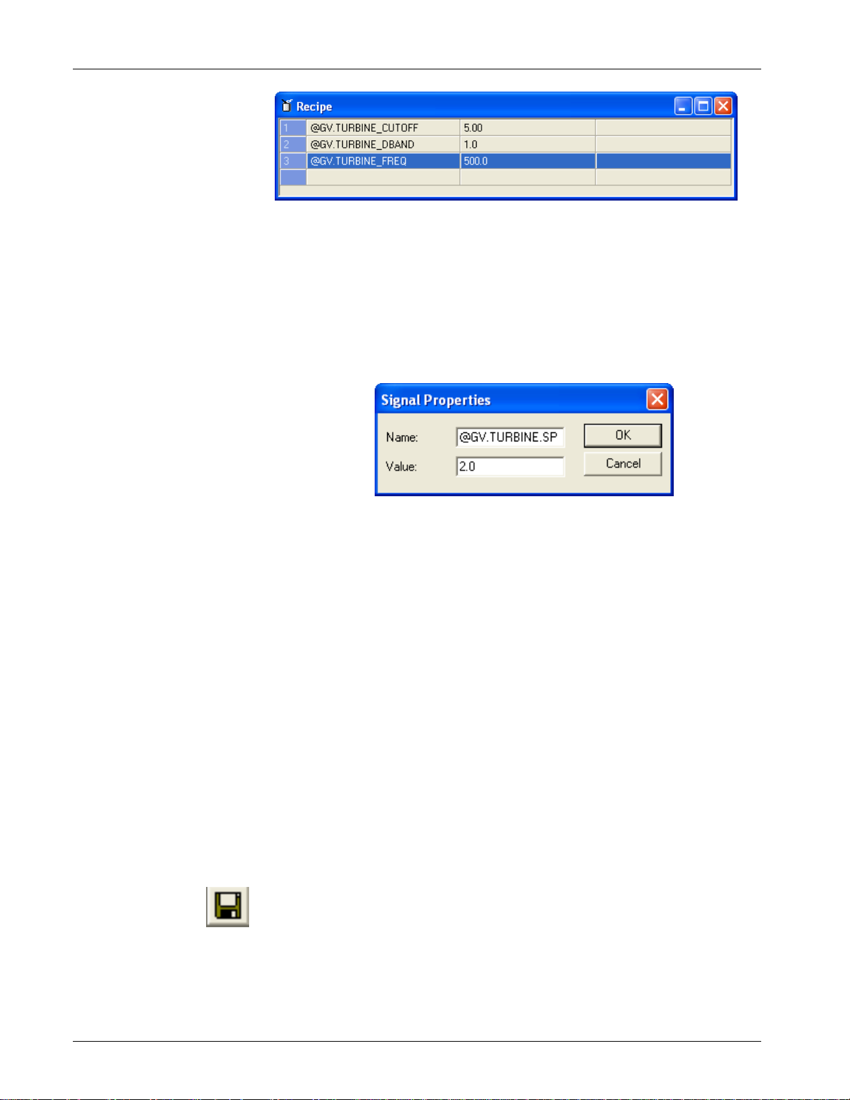
Figure 3-12. Recipe Window
Click Edit>Insert and the Signal Properties dialog box opens. Enter a
signal name in the Name field, and a value for the signal in the Value
field, then click OK. DataView inserts the signal on the currently
highlighted line, and pushes down any entries that begin on that line.
Repeat this step for each additional signal you want to include in the
Recipe.
Figure 3-13. Adding Signals to the Recipe
\\
Although DataView performs no verification with the remote load when
you create the recipe, you should remember that if you enter a logical
signal in the recipe, only two values are valid: 1.0 for ON, and 0.0 for
OFF.
If you make a mistake on a particular line, click on the line you want to
change, then click Edit>Modify; the Signal Properties dialog box
opens, allowing you to edit the signal name and/or value.
If you want to delete a particular line, click on the line you want to
delete, then click Edit>Delete. DataView prompts you to confirm that
you want to delete the line from the Recipe; click Yes and DataView
removes that signal from the Recipe.
Recipes can include up to 10,000 lines.
3.10.2 Saving the Recipe
When the Recipe is complete, you must save it by clicking on the icon,
shown at left, or click File>Save As. Assign a name to the Recipe file
using the Windows Save As dialog box. All Recipes have a file
extension of (.RCP).
To save modifications to a previously saved Recipe, click the Save
toolbar icon, shown above, or click File>Save.
3-16 DataView Issued Sep-2012
Page 31

ControlWave Utilities Manual (D5142)
3.10.3 To View/Modify an Existing Recipe File
The File pull down menu displays the names of the last four files viewed
(of all file types). If the Recipe (.RCP) file you want to view appears in
the menu, you can open the file by simply clicking on the file name. To
view any other Recipe (.RCP) file, click the Open File tool bar icon,
shown above, or click File>Open. Select the recipe file from the Open
File dialog box, and the recipe displays on the screen in a recipe
window. Assuming OpenBSI is already running, you can also open a
Recipe if you double-click on the RCP filename in Windows.
You can make modifications to signal names in the recipe by clicking
on the line you want to change, and choose Edit>Modify. You can then
change the signal name and/or value using the Signal Properties dialog
box. You can also change recipe values by overwriting the values with
the current values in the controller (see To Read the Current Signal
Values from the Controller into the Recipe Window).
3.10.4 To Update Signals in the Controller with the Recipe Values
Bring up the recipe to view (described above under To View/Modify an
Existing Recipe File) and click Recipe>Write to RTU. The Select New
Node dialog box opens. Select the node which you want to receive the
new values and sign-on to that node; DataView writes the values to the
corresponding signals in the node. Note: In order to update the signals,
you must manually enable them.
3.10.5 To Read the Current Signal Values From the Controller Into
the Recipe Window
Bring up the recipe to view (described above under To View/Modify an
Existing Recipe File). Next, click on Recipe>Read from RTU. The
Select New Node dialog box opens. Select the node which will provide
the new values and sign-on to that node. DataView copies the values in
the node, for the signals in the recipe, into the window.
3.10.6 To Cancel Unsaved Modifications to the Recipe Values
If you made changes to recipe values in the recipe window, but have not
saved them, and you want to cancel the changes, and return to the
previously saved recipe values, click Recipe>Reload. DataView
restores the previously saved recipe values into the recipe window.
3.10.7 Changing the Floating Point Format of Data in the Recipe
Window
You can change the floating point format in which DataView presents
signal values. See the sub-section on floating point formats in the
Viewing Entries in the Signal Window section.
Issued Sep-2012 DataView 3-17
Page 32

ControlWave Utilities Manual (D5142)
eadbands
y
3.11 Viewing Data for a Single Signal
You can view detailed signal information by clicking on a signal name
in any Signal Window you open using DataView's Signal Search,
DataView List, or Remote List features. Alternatively you may also
view detailed information on a single signal by clicking on the Signal
Detail toolbar icon (shown above) or you can click File>New, and then
select Signal Detail from the list box. The Signal Detail Properties
dialog box opens.
Field Tools automatically completes the Node list box for you. Enter the
complete signal name i.e. base.extension.attribute and click OK.
(RED indicates
currently in
alarm state)
Signal Value
Read Priority
Inhibit/Enable Bits
Alarm Limits
Alarm
D
Figure 3-14. Signal Detail Properties dialog box
Signal / Variable Name
Node Name
Units Text
Descriptive Text
MSD Address
(Emerson use only)
Write Priorit
Alarm Acknowledge
Alarm Priority:
Critical
Non-Critical
Operator Guide
Event
Show / Hide
alarm limits
and deadbands
Current Alarm State: On = In Alarm
Off = Not in Alarm
Alarm Report State:
Blank = no report
Mo = momentary alarm
Mult = multiple alarms
Single = one alarm
Ack Status:
Acked = Acknowledged
NotAck= Not acknowledged
Figure 3-15. Signal Detail Window
3-18 DataView Issued Sep-2012
Page 33

ControlWave Utilities Manual (D5142)
A Signal Detail window contains the signal name, base name
descriptive text, inhibit/enable bit values, signal value, units text or
ON/OFF text, read priority, write priority, and other data. The figure
above shows the window for an analog alarm signal. If you want, you
can change the signal's value, or alter the inhibit/enable bits by clicking
on those fields, and entering the new data via a dialog box.
3.11.1 Acknowledging an Alarm
If the signal you view is an alarm signal in an alarm state, and this alarm
has not been acknowledged (as indicated by an exclamation point “!”
next to the signal's value) you can acknowledge the alarm if you click
on the Ack Alarm button. A message box opens indicating the status of
the acknowledgment operation.
3.12 Viewing Data Arrays
To view a Data Array in the controller, click on the Array tool bar icon
(shown above) or click File>New, then select Array.
The Array Properties dialog box opens. Choose the node which contains
the array using the Node list box. Specify the Array Type as either
analog or logical.
Figure 3-16. Array Properties dialog box
Use the Array Num list box to determine which arrays exist in the
controller. Select the array from the list box, or enter the array number
in the box. If the array is large, and you want to begin viewing from
some row other than 1, enter that row in the Starting Row field.
Click OK; and DataView displays the array.
Note: If you cannot see a list of arrays using the Array Num list box, it
means DataView does not have access to your control strategy
file.
Issued Sep-2012 DataView 3-19
Page 34

ControlWave Utilities Manual (D5142)
If this is a large array, a scroll bar appears to let you view portions
which do not currently fit in the window.
The lower right corner of the window displays the total number of array
rows, total number of array columns, and the current operator security
level.
Number of rows
Error / status messages
Current operator security level
Number of columns
Figure 3-17. Array Window
3.12.1 Changing Values in the Data Array
If this is a read-write array, you can alter data array values if you click
on the array cell you want to change, and enter a new value using the
Change Value dialog box.
3-20 DataView Issued Sep-2012
Page 35

ControlWave Utilities Manual (D5142)
Figure 3-18. Change Value dialog box
3.12.2 Toggling the Time/Value Format
Depending upon how you configure the data array, it may include Julian
date/time stamps in the first column. To convert these time/date stamps
to the numerical total used by the system to store the date and time, and
vice versa, click Format> View First Column as Date/Time.
3.12.3 Keeping Column 1 Visible While Scrolling Through the Array
As you scroll through columns of the data array, the first column (which
may contain date/time stamps) may disappear from the window as
higher numbered columns come into the window. To prevent this, click
the icon, shown above, or click Format>Freeze First Column.
3.12.4 Calling Up a Different Data Array
Once a data array opens in the window, you can replace it with a
different data array by clicking on the Properties tool bar icon, or by
clicking Format>Properties. Either of these actions will re-open the
Array Properties dialog box, from which you can select a different array.
3.12.5 Changing the Floating Point Format
Like analog data presented in a signal window, you can alter the floating
point format for data in array windows. (See Changing the Floating
Point Format of Data in the Signal Window in the Viewing Entries in a
Signal Window section.)
3.13 Viewing Audit Trail Records
To view Audit Trail buffer entries from the Audit function block, click
the Audit tool bar icon, shown at left, or click File>New, then select
Audit from the New list box.
The Audit Collection dialog box opens.
Issued Sep-2012 DataView 3-21
Page 36

ControlWave Utilities Manual (D5142)
Figure 3-19. Audit Collection dialog box
Choose the controller
containing the audit
records you want to
view.
Choose the type of
audit information you
want to collect.
Choose how much audit
information you want to
collect.
Choose the order in
which audit records are
displayed.
First, choose the controller (RTU) from which you want to collect audit
records using the Node list box.
Then choose whether you want to retrieve alarms, events, or both.
If you choose Collect All Available Records, DataView collects all
audit records in the RTU.
Use the Start Date to specify the first date from which data will be
displayed. Depending on the Direction you choose, all following lines
of data will either be from before that date, or since that date.
If you choose Specified Period you can request audit records only from
a set period of time. Choices are records from Today, This Week or This
Month.
The Direction specifies the order in which the window displays the audit
records. From Oldest to Newest displays the earliest records first. From
Newest to Oldest displays the most recent audit records first.
Click OK to begin the collection. DataView displays the Audit Trail
buffer entries in a window on the screen. Use the scroll bar to view any
portions not currently visible.
Notes:
The total number of entries which have been collected appears in the
status bar at the bottom of the window. If this number appears with a
cyan (light blue) background, then additional entries have not yet
been collected from the controller.
DataView cannot show more than 1,000 Audit Trail buffer entries.
Any audit entries already collected using the OpenBSI Harvester, or
the Historical Log Storage control, are inaccessible to DataView.
3-22 DataView Issued Sep-2012
Page 37

ControlWave Utilities Manual (D5142)
Timestamp Text describing alarm / event
Local
Sequence
Number
Global Sequence Number
Figure 3-20. Viewing Audit Records
To re-open the Select New Node dialog box to choose a different node,
click the Properties tool bar icon, shown above, or click
Format>Properties.
Number of Entries
Current Operator Security Level
Issued Sep-2012 DataView 3-23
Page 38

ControlWave Utilities Manual (D5142)
3.14 Viewing Archive Data Files
If your controller has archive data, you can view it, in DataView, if you
click on the Archive tool bar icon, shown at left. Alternatively, you can
click File>New, and then select Archive from the list box. Either of
these methods opens up the Archive Properties dialog box.
Figure 3-21. Archive Properties dialog box
Select the RTU name from the Node list box, and enter the number of
the archive file you would like to view in the File Number field. If you
would like the oldest archive file entries to appear first, check the Start
from oldest record box.
After you choose the Node and File Number, click OK to display the
selected archive file.
The archive file opens in a window. Use the scroll bar to view portions
of the file not currently visible.
Figure 3-22. Archive File
3-24 DataView Issued Sep-2012
Page 39

ControlWave Utilities Manual (D5142)
Notes:
DataView cannot display more than 1000 archive records from a
particular archive file.
The total number of entries which have been collected appears in
the status bar at the bottom of the window. If this number appears
with a cyan (light blue) background, then additional entries have not
yet been collected from the controller.
DataView can display string-based archives.
3.14.1 Keeping Column 1 Visible While Scrolling Through the
Archive File
As you scroll through the archive file window, the first column (which
may contain date/time stamps) may disappear from the window as you
bring higher numbered columns into the window. To prevent this, click
the icon, shown at left, or click Format>Freeze First Column.
3.14.2 Calling Up a Different Archive File
Once you open an archive file in the window, you can replace it with a
different archive file if you click the Properties tool bar icon, or click
Format>Properties. Either of these actions re-opens the Archive
Properties dialog box, from which you can select a different archive file.
3.14.3 Changing the Floating Point Format
Like analog data presented in a signal window, you can alter the floating
point format for data in the archive window. (See Changing the
Floating Point Format of Data in the Signal Window in the Viewing
Entries in a Signal Window section.)
3.14.4 Restrictions on Archive File Size
When you use DataView to collect Archive files over a serial
connection, you can only display archive records that are 220 bytes or
less. The system uses a total of four bytes of the 220 to display the
timestamp, plus two bytes to store the local sequence number, and two
bytes to store the global sequence number. This leaves 212 bytes for
other columns of data. This could include up to 53 columns of floating
point data.
Table 3-3. Archive File Sizing
Type of Data Number of Bytes Required
Timestamp 4
Local Sequence Number 2
Global Sequence Number 2
Issued Sep-2012 DataView 3-25
Page 40

ControlWave Utilities Manual (D5142)
Analog Floating Point value 4
Logical / BOOL value 1
Type of Data Number of Bytes Required
3-26 DataView Issued Sep-2012
Page 41

ControlWave Utilities Manual (D5142)
Chapter 4 – Using the Downloader
When you finish creating your control strategy file using ControlWave
Designer you have to transfer it to the actual controller; this process is
called downloading.
In This Chapter
4.1 Downloading to a ControlWave-series Node: .................................. 4-1
4.1.1 Before You Begin ................................................................. 4-1
4.1.2 Starting the ControlWave Downloader ................................. 4-4
4.1.3 Using the ControlWave Downloader .................................... 4-4
The ControlWave Downloader transfers an IEC 61131 ControlWave
project from the Field Tools laptop to a running ControlWave series
RTU.
Never attempt to download an untested program into an RTU currently
Warning
running an industrial process or plant. Prior to downloading, isolate the
RTU from the process and disconnect I/O. Failure to take such
precautions could result in injury to persons or damage to property.
4.1 Downloading to a ControlWave-series Node:
Note: You can also download a project to a ControlWave directly from
within ControlWave Designer. See the ControlWave Designer
documentation for details.
4.1.1 Before You Begin
There are certain things you must do before you can download to a
ControlWave-series controller.
You must save your project as a ControlWave project *.MWT file.
You must generate a boot project file during compilation in
ControlWave Designer. To do this, you must check the Generate
bootproject during compile box for your resource.
Issued Sep-2012 Downloader 4-1
Page 42

ControlWave Utilities Manual (D5142)
Make sure this box is checked in
ControlWave Designer when you
compile/build your project.
Figure 4-1. Generating a Bootproject During Compilation
You must generate a zipped project file (*.ZWT) in ControlWave
Designer. One way you can do this is to manually save your
ControlWave project as a zip file:
First click the “Save Project As/Zip
Project As” option in ControlWave
Designer.
Next, make sure you choose “Zipped
Project Files (*.zwt) in the Save as
type list box, or else the project won’t
be zipped.
Finally, click the “Zip” button.
Figure 4-2. Zipping Your ControlWave Project
4-2 Downloader Issued Sep-2012
Page 43

ControlWave Utilities Manual (D5142)
Use the “…” button to specify the directory which will hold
your download files. When you initiate a transfer, the utility
creates a sub-directory of the download directory to hold
the boot and zip files for this particular project.
If you didn’t
generate a ZWT file
yet, check this box
and the utility does
it for you.
Click here to start the transfer.
Figure 4-3. Transferring the Project File to the Download Directory
You must transfer the bootfile and zip file for this project to a sub-
directory of whichever directory you want to use for downloads.
You can accomplish this if you click Build > Transfer Download
Files in ControlWave Designer. In this utility, you must specify the
download directory in the Download dir field. (See Figure 4-3.)
If you check Zip Project and Transfer Zip File (default), the
system zips the current project automatically, in preparation for the
transfer. If you select the Compress user libraries into download
project option, the system zips the user libraries and includes them
in the zip project.
Note: Zip Project and Transfer Zip overwrites any pre-existing zip
file for this project. To prevent this, you can disable the option,
however, if you do, you must have a previously created zip
available for transfer.
When you finish making selections, click Transfer and the file
transfer begins.
If your ControlWave-series node includes a key operated RUN /
REMOTE/ LOCAL switch, you must turn the switch to either the
REMOTE or LOCAL position, depending upon how the PC
connects to the ControlWave. Downloading CANNOT occur with
the switch in the RUN position.
Issued Sep-2012 Downloader 4-3
Page 44

ControlWave Utilities Manual (D5142)
4.1.2 Starting the ControlWave Downloader
Note: Before starting the Downloader, you must establish
communications with the controller using Field Tools, then
launch TechView.
Right-click on the icon for the controller name in TechView, and choose
Downloader from the pop-up menu.
4.1.3 Using the ControlWave Downloader
When the ControlWave Downloader dialog box opens, complete the
fields as described, below:
Field Tools uses the RTU
credentials setting to supply the
proper username and password
for this controller.
Click here to start the download.
RTU node name
(populated
automatically by
Field Tools)
Check this to allow
the ZWT file to
download.
Shows the
progress of the
download.
When downloading a project, click “Warm Boot” to perform a
warm download (project is started from the beginning using
values saved as RETAIN – if project hasn’t changed to a degree
that those values don’t apply). If you de-select “Warm Boot” a
cold download occurs (project is started from the beginning
using initial values.
Use this browse
button to choose
the sub-directory
containing your
bootfile.pro and
.zwt file.
Use this browse button to
choose the sub-directory
containing user files. You
Check this box to download
user files (.HTML, etc.) which
the ControlView utility can
retrieve later.
can use the ControlView
utility to retrieve these.
Figure 4-4. ControlWave Downloader
When the fields are completed, click Begin to start the download. The
fields/buttons in this dialog box are:
Field Description
Node
4-4 Downloader Issued Sep-2012
This displays the node name for this ControlWaveseries controller.
Page 45

ControlWave Utilities Manual (D5142)
Username, Password
Project Path
User Files Path
Begin
Field Tools automatically populates these fields with
the RTU credentials. If you didn’t specify RTU
credentials, enter a valid username/password
combination for this ControlWave-series controller.
Enter the path of the project that the Downloader will
download to this controller, or use the Browse
Bootfile button to locate it. (The path must be a sub-
directory of whichever directory you specified for
downloads (Download Dir) in the Transfer Download
Files dialog box, Figure 4-3) The project files consist of
the .PRO boot file, generated when you compile your
ControlWave project, and the zip file (*.zwt) containing
the project source. Note: If your project includes
multiple resources, each one has a different path, and
you must choose the appropriate on e.
Enter the path of the folder con taini ng files y ou want to
download to the user files area of the ControlWave, or
use the Browse Path button to locate it. (See
Download User Files, below).
Click here to start the download.
Cancel
Warm Boot
ZipFile
Download
User Files
Click here to exit down the Downloader.
When you don’t select this check box, all variables
initialize as part of the download, and the project
restarts. When you choose Warm Boot, any variables
configured as RETAIN do not re-initialize as part of the
download, however, all other variables initialize, and
the project restarts from the beginning of its cycle.
When you select this option, the download operation
includes the zipped project file (*.ZWT).
The ControlWave can store user files (*.ZIP, *.HTML,
etc.) in flash memory, for later retrieval using the
ControlView utility. You must place the user files you
want to download to the ControlWave in the folder
identified by the User Files Path field.
Issued Sep-2012 Downloader 4-5
Page 46

This page is intentionally left blank
Page 47

ControlWave Utilities Manual (D5142)
Chapter 5 – Using the Flash Configuration utility
The Flash Configuration utility lets you configure IP and local addresses
as well as configuration parameters for security, communications, and
historical data collection.
In This Chapter
5.1 Starting the Flash Configuration Utility ............................................ 5-1
5.2 Flash Configuration Utility Buttons .................................................. 5-4
5.3 Forcing a Reboot of the ControlWave ............................................. 5-6
5.4 Flash Configuration Utility Tabs ....................................................... 5-7
5.5 Soft Switches ................................................................................... 5-8
5.6 Ports ................................................................................................. 5-9
5.6.1 IP Network Security Protocols (CHAP and PAP) Used on PPP
Links .................................................................................. 5-14
5.6.2 Challenge Handshaking Authentication Protocol (CHAP) . 5-15
5.6.3 Password Authentication Protocol (PAP) ........................... 5-18
5.7 IP Parameters ................................................................................ 5-25
5.8 Application Parameters .................................................................. 5-30
5.9 Archive ........................................................................................... 5-32
5.10 Audit ............................................................................................... 5-37
5.11 IP Routes ....................................................................................... 5-40
5.12 Security .......................................................................................... 5-42
5.1 Starting the Flash Configuration Utility
Note: Before starting the Flash Configuration utility, you must establish
communications with the controller using Field Tools, then launch
TechView.
To start the Flash Configuration utility from TechView click
Operations > Access Flash Parameters, or click on the icon, shown
above.
Note: In order to use the Flash Configuration utility to view or change
parameters in a ControlWave series controller, the user you
specified in the RTU credentials dialog box in Field Tools
(username / password) must have administrative privileges. For
an all-new ControlWave, use the administrative username
“SYSTEM” and the password “666666.”
Certain options in the Flash Configuration utility don’t require you to
establish communications with the RTU. If while the utility begins to
establish communications you decide you want to use the utility offline,
you can click Cancel Initialization and Continue to do that (Figure 5-
1). If, for some reason, the utility cannot establish communications, you
can shut down the utility if you click on Cancel Initialization and
Abort.
Issued Sep-2012 Flash Configurator 5-1
Page 48

ControlWave Utilities Manual (D5142)
Once the Flash Configuration utility establishes communication with the
RTU, you can optionally specify the source for the initial parameters
displayed in the utility (Figure 5-2).
Figure 5-1. Cancel Initialization dialog box
Figure 5-2. Flash Configuration Loading Options dialog box
The choices for this are described below.
Field Description
Load from device This prompts you to log into the RTU. The utility then
loads the current parameters from the RTU into the
Flash Configuration utility pages.
Load from FCP file
5-2 Flash Configurator Issued Sep-2012
This prompts you to specify the location and
filename of a Flash Configuration Profile (FCP) file.
FCP files are files you can use to store flash
parameters on the Field Tools laptop. This simplifies
your configuration because once you store these
parameters in an FCP file you can optionally re-use
the FCP file to load the same flash parameters into a
different RTU. That way, you don’t have to re-enter
everything for each RTU. Once you specify the FCP
Page 49

ControlWave Utilities Manual (D5142)
filename, the utility loads the current parameters
from the FCP file into Flash Configuration Utility
pages.
Load from Network
Definition File
Load defaults based on
RTU type
Do not show this
dialog box again
Not applicable when invoking this utility from within
Field Tools.
This choice causes the utility to copy some basic
flash parameters into the pages of the Flash
Configuration utility. These basic parameters are
based on default settings for the type of RTU.
If you check this box, the Loading Options dialog box
does not appear again in subsequent Flash
Configuration sessions, and the last loading option you
choose becomes the default.
Click OK to finalize your choice and exit the dialog box. Parameters
load into the Flash Configuration utility pages based on your choice, or
you answer prompts to load them from the RTU or FCP file.
If you want to prevent the Loading Options dialog box from appearing,
right-click on the title bar of the Flash Configuration utility, and choose
Settings to bring up the Settings dialog box. You can un-check the
Show Loading Options dialog box at startup. You can also check
Close Transfer dialog box to automatically close the transfer dialog
box after a successful transfer. Click OK to exit the Settings dialog box.
Figure 5-3. Settings dialog box
The Flash Configuration utility includes different pages for different
types of parameters. To access them, click on the tab for a particular
page.
Issued Sep-2012 Flash Configurator 5-3
Page 50

ControlWave Utilities Manual (D5142)
g
Click on any of these tabs to bring
up other pages of the Flash
Configuration utility.
This button reads the
current configuration
from the controller into
the utility.
This button saves
ALL changes to the
controller.
This button reads the
current configuration
from the Flash
Configuration (FCP) file.
This button saves
ALL changes to the
FCP file.
This button shuts down the Flash
Confi
uration utility.
Figure 5-4. Flash Configuration Utility
5.2 Flash Configuration Utility Buttons
The Flash Configuration utility contains several buttons, primarily for
read/write file operations. The Flash Configuration utility buttons
include:
Button Description
Apply New Node Not applicable when invoking this utility from within Field
Tools.
Sign On
Read From RTU
Not applicable when invoking this utility from within Field
Tools.
Click here to read the current configuration characteristics
directly from the controller, and copy them into the pages
of the Flash Configuration utility.
5-4 Flash Configurator Issued Sep-2012
Page 51

ControlWave Utilities Manual (D5142)
Write To RTU Click here to save all entries in all pages of the Flash
Configuration utility to th e controll er. The ut ility prom pts
you to confirm you want to write to the flash memory.
Warning
The Flash Configuration Utility displays the progress of the
save operation.
After the write operation to the ControlWave completes,
the Flash Configuration utility assesses whether or not
the changes require you to reset the ControlWave. If the
utility determines that you must reset it prompts you to
do so.
During the reset process, your controller performs no measurement or
control of your process. Ensure you have backup control mechanisms
in place during the reset process. Failure to take such precautions
could result in injury to persons or damage to property
Issued Sep-2012 Flash Configurator 5-5
Page 52

ControlWave Utilities Manual (D5142)
Read From FCP Click here to read the current configuration of this
Click Yes for the system to stop any currently running
project and reboot the ControlWave unit immediately;
changes then take effect. Click No if you want to manually
reboot the unit later; changes do not take effect until the
reboot. See Section 5.3 for information on fo rcing a
reboot.
controller, as specified in a Flash Configuration Profile
file (*.FCP), and copy it into the pages of the Flash
Configuration utility. You can then subsequently copy
the configuration into the controller using the Write To
RTU button.
The Flash Configuration utility does not perform any validation checks
Caution
on an FCP file when it opens it. Therefore, we recommend you do NOT
attempt to edit the FCP file manually with a text editor, because you
could corrupt the profile file. Recommended best practice is to edit the
FCP only through the Flash Configuration utility.
Write To FCP Click here to copy all entries made in the Flash
Configuration utility for the current controller into the
Flash Configuration Profi le file (*.F CP).
Read From NDF Not applicable when invoking this utility from within
Field Tools.
Write To NDF
Close
Not applicable when invoking this utility from within
Field Tools.
Click here to shut down t he Fl ash Co nfigura tion Utility .
5.3 Forcing a Reboot of the ControlWave
You can reset the ControlWave, at any time, using the Flash
Configuration utility. To do this, right-click on the title bar, and choose
Reset Rtu from the pop-up menu:
5-6 Flash Configurator Issued Sep-2012
Page 53

ControlWave Utilities Manual (D5142)
Figure 5-5. Forcing a Reboot of the ControlWave
5.4 Flash Configuration Utility Tabs
The Flash Configuration utility contains multiple pages; you access a
page by clicking on its tab. The various tabs include:
Soft Switches - the most important of these is the BSAP local
address of the controller. (See Section 5.5.)
Ports - this includes all communication ports on the controller -
serial BSAP ports, serial IP ports (PPP), and Ethernet IP ports. Some
controllers also support other port types. (See Section 5.6.)
IP Parameters - if this controller performs IP communications, you
must configure certain parameters such as the IP address of the
Network Host PC (NHP), UDP socket numbers, and the address of
the default gateway. (See Section 5.7.)
Application Parameters - Most of these are “tuning” parameters
which govern how the ControlWave executes its application
(project). (See Section 5.8.)
Archive - Archive data is one portion of the historical capabilities of
the ControlWave controller. It allows you to save “snapshots” of
many variables at the same instant, to provide a detailed historical
record of process variables at a particular moment in time. The
controller stores the archive data in structures called archive files.
You configure the archive feature, in part, using the ARCHIVE
function block in your ControlWave project. Utilities such as
DataView can collect and display the archive data. (See Section 5.9.)
Audit Audit logging is one portion of the historical capabilities of
the ControlWave controller. It allows you to save records of when
certain variables change value, as well as records of all alarms in the
system. Use the Audit page to specify various parameters used to set
up the Audit system. You also need to configure the AUDIT
function block in your ControlWave project. (See Section 5.10.)
IP Routes - Dynamic IP routes allows the ControlWave to take
messages which cannot successfully reach a particular destination
address, to re-route them through a different path in the IP network.
(See Section 5.11.)
Issued Sep-2012 Flash Configurator 5-7
Page 54

ControlWave Utilities Manual (D5142)
Security - This page allows you to configure user accounts and
privileges. (See Section 5.12 .)
5.5 Soft Switches
To reach the “Soft Switches” page, click on the “Soft Switches” tab in
the Flash Configuration utility.
Figure 5-6. Soft Switches Page
Complete the fields as described below:
Field Description
Local Address
EBSAP Group
Specify the BSAP local address here, which must be
an integer from 1 to 127. The default is 1. The BSAP
local address is important even in non-BSAP networks
to ensure proper routing of alarm and RBE messages.
Specify the EBSAP group number here; if this node
does not use expanded node addressing (EBSAP),
enter “0” for the group number.
5-8 Flash Configurator Issued Sep-2012
Page 55

ControlWave Utilities Manual (D5142)
5.6 Ports
To reach the “Ports” page, click on the “Ports” tab in the Flash
Configuration utility. The numbers and types of ports shown for
configuration vary depending upon the type of controller.
To configure a particular port, click on its icon in the left part of the
page, and the right part of the page will display the parameters for that
port (which can further change depending upon the mode and how you
configure the port).
Caution
Figure 5-7. Ports Page
When configuring ports in the Flash Configuration utility, exercise
care regarding the port through which you are currently
communicating using TechView. For example, if you change the baud
rate for the serial port on which you are currently communicating and
click “Write to RTU” all communications on that port immediately
cease because you now made the baud rates incompatible with the
current baud rate setting in TechView.
If you do this accidentally, you can re-start the TechView session
using a new baud rate or you can re-establish communications by
setting the “Use/Ignore Soft Switches” switch (also referred to as the
“default switch”) on your CPU module to OFF, and then re-connect to
one of the serial ports using the factory default baud rate setting. See
your ControlWave hardware manual for details on switches and
default baud rates for particular ports.
Sub-sections follow which describe the configuration for each type of
port.
Issued Sep-2012 Flash Configurator 5-9
Page 56

ControlWave Utilities Manual (D5142)
t
t
t
r
Ethernet Port
Parameters
The Ethernet port parameters specify the IP address of this RTU's
Ethernet port(s), as well as the range of IP addresses to which this RTU
can send messages. To access the Ethernet Port Parameters, click the
“ENET” icon in the "Ports" list box. Some controllers support up to
three Ethernet ports (ENET1 through ENET3).
Figure 5-8. Ethernet Port Parameters
Field Description
IP ADDR A
"P ADDR B"
IP MASK This lets you specify the range of valid IP addresses
This lets you specify the IP address of the Etherne
Port on the RTU, or, if this RTU is the “A” unit of a
redundant pair of RTU's, the IP address for its
Ethernet Port as part of the redundant pair. You mus
enter a unique IP address in dotted decimal format.
This lets you specify the IP address of the Etherne
Port on the “B” unit of a redundant pair of RTU's. If this
RTU is NOT part of a redundant pair, specify an
address of 0.0.0.0. If the RTU is part of redundant pair,
you must enter a unique IP address in dotted decimal
format.
which this RTU can send messages to through this
port. You must enter the mask in dotted decimal
format. The default is 0.0.0.0 (all devices are
reachable). Each part of the "IP MASK" can only be
one of the following numbers: 255, 254, 252, 248, 240,
224, 192, 128, or 0. These values correspond to a
decimal representation of the number of bits in the IP
addresses of all nodes, reachable through this port,
which must match exactly. If you enter anything othe
than "255" in a particular part of the "IP MASK" field,
you must set all fields to the right to 0.
BSAP Slave /
EBSAP Slave
Port Parameters
Use these parameters to specify the baud rate used for BSAP cold
downloads through the selected serial port. ControlWave serial ports
range from COM1 to COM11 depending upon the type of unit.
5-10 Flash Configurator Issued Sep-2012
Page 57

ControlWave Utilities Manual (D5142)
f
t
p
Figure 5-9. BSAP Slave / EBSAP Slave Port Parameters
Field Description
Mode
Baud Rate
Choose either BSAP Slave if this controller belongs to
a BSAP network (or sub-network) or EBSAP Slave i
this controller belongs to an EBSAP network.
The baud rate you enter for the ControlWave here
applies to any usage of this port. In addition, if the por
already exists, changes made here are immediate,
and do not require you to reset the unit.
User Mode Port
Parameters
Use these parameters to configure a customized serial data link
rotocol. For ControlWave controllers, the serial ports range from
COM1 to COM11 depending upon the type of unit.
Figure 5-10. User Mode Port Parameters
Issued Sep-2012 Flash Configurator 5-11
Page 58

ControlWave Utilities Manual (D5142)
t
y
y
Field Description
Mode
Baud Rate
Bits Per Char
Stop Bits
Parity
User Mode
P1
P2
PPP Port
Parameters
PPP (Point-to-Point Protocol) ports allow serial IP communication.
Use these parameters to specify the baud rate used for BSAP cold
downloads through the selected serial port. For ControlWave
controllers, the serial ports range from COM1 to COM11 depending
upon the type of unit.
Choose USER_MODE.
Specify the baud rate for your customized protocol.
The default value for baud rate is 9600.
The baud rate you enter for the ControlWave here
applies to any usage of this port. In addition, if the por
already exists, changes made here are immediate,
and do not require you to reset the unit.
Specify the number of bits in a character for this
custom protocol. The default is 8.
Specify the number of stop bits per character for this
custom protocol. The default is 1.
Specify ODD, EVEN, or NONE for the parity. The
default is NONE.
Specify a protocol number which the firmware uses to
reference internal and custom tables at the RTU, in
order to select the proper driver software for this
custom data link.
This is is a protocol-specific value which a non-
standard protocol uses at RTU initialization. Its value is
4 bytes unsigned, and defaults to 0. (This field is onl
for non-standard, customized data links.)
This is a second protocol-specific value which a nonstandard protocol uses at RTU initialization. Its value is
4 bytes unsigned, and defaults to 0. (This field is onl
for non-standard, customized data links.)
5-12 Flash Configurator Issued Sep-2012
Page 59

ControlWave Utilities Manual (D5142)
t
t
r
A
r
Figure 5-11. PPP Port Parameters
Field Description
Mode
Baud Rate
IP ADDR
IP MASK
Server Security
Choose PPP.
Specify the baud rate for serial IP Point-to-Poin
Protocol (PPP) communication. The default is 9600.
For ControlWave-series controllers, the baud rate you
enter here applies to any usage of this port. In
addition, if the port already exists, changes made here
are immediate, and do not require you to reset the
unit.
Specify the IP address of this serial IP port. You mus
enter a unique IP address in dotted decimal format.
This lets you specify the range of valid IP addresses
which this RTU can send messages to through this
port. You must enter the mask in dotted decimal
format. The default is 0.0.0.0 (all devices are
reachable). Each part of the IP MASK can only be one
of the following numbers: 255, 254, 252, 248, 240,
224, 192, 128, or 0. These values correspond to a
decimal representation of the number of bits in the IP
addresses of all nodes, reachable through this port,
which must match exactly. If you enter anything othe
than "255" in a particular part of the IP MASK field,
you must set all fields to the right to 0.
This parameter only applies to ControlWave-series
controllers which serve as Password Authentication
Protocol (PAP) / Challenge Handshaking
uthentication Protocol (CHAP) servers. Choose
Plain Text (PAP) to designate this controller as a PAP
Server, Encrypted (CHAP) to designate this controlle
as a CHAP Server, or None if you do not intend to
Issued Sep-2012 Flash Configurator 5-13
Page 60

ControlWave Utilities Manual (D5142)
r
p
implement CHAP or PAP.
Notes About
Using PAP/CHAP
on a PPP Link
Client Security
This parameter only applies to ControlWave-series
controllers which serve as PAP/CHAP clients. Choose
Plain Text (PAP) to designate this controller as a PAP
Client, Encrypted (CHAP) to designate this controlle
as a CHAP Client, or None if you do not intend to
implement CHAP or PAP.
You can implement either the PAP or CHAP protocol as a security
measure on the PPP link. CHAP is the more secure of the two
rotocols. The basic configuration steps at the ControlWave are the
same for both.
1. Define user accounts on the “Security” page of the Flash
Configuration utility (described later in this chapter).
2. On the “Ports” page for the PPP link, use the Client Security or
Server Security choice (described above) to specify whether this
ControlWave port is a client or a server, and choose the security
protocol for it - PAP or CHAP. Clients initiate a request for access,
and servers validate the request. If you configure more than one PPP
port, you can configure a client on one port, and a server on another
port.
3. On the “IP Parameters” page of the Flash Configuration Utility
(described later), choose whichever user account you want to use for
PAP/CHAP transmissions in this controller.
For a more detailed explanation of PAP/CHAP, see Section 5.6.1.
5.6.1 IP Network Security Protocols (CHAP and PAP) Used on PPP Links
While not required, we strongly recommend you consider using one of
the two supported security protocols (PAP and CHAP) to help prevent
unauthorized access to your network by an intruder (hacker). Typically,
you should use CHAP since it is more secure.
The PAP and CHAP protocols operate in a client/server arrangement.
The ControlWave RTU operates as a CHAP (or PAP) server. Either a
ControlWave RTU or an OpenBSI workstation operates as a CHAP (or
PAP) client. Any client must always supply a valid username/password
combination to gain access to the server.
If the OpenBSI workstation is the client, you enter the username and
password directly in response to a login prompt. These must match one
of the username / password combinations stored in the ControlWave.
If a ControlWave RTU is the client, use the "Challenge Protocol
Default Username" field in the “Ports” page of the Flash Configuration
Utility to enter the username. The RTU automatically transmits the
5-14 Flash Configurator Issued Sep-2012
Page 61

ControlWave Utilities Manual (D5142)
username / password text string for that username in response to a login
prompt from the server.
Both of these security methods are similar at the user level. The
difference is in the underlying operation of the protocols.
5.6.2 Challenge Handshaking Authentication Protocol (CHAP)
The CHAP server (ControlWave) issues an encrypted challenge
message (which appears as a normal login prompt) to any CHAP client
(workstation or ControlWave) that requests access. CHAP encrypts the
supplied username and password according to a pre-defined secret
encryption key. The result is called the response message.
Even though the username / password combination for a particular user
does NOT change on each login attempt, the encrypted challenge and
response messages are different on each attempt. This helps prevent an
intruder from replicating the proper response message for a given
challenge message, either through trial and error or “brute force”
searches of all possible challenge messages.
Another characteristic of CHAP is that even after the client logs in,
subsequent challenge / response transactions occur to verify that the
connection is still with a valid user.
Example 1 - In this first CHAP example, the CHAP client is a PC
workstation, and the CHAP Server is a ControlWave RTU.
Issued Sep-2012 Flash Configurator 5-15
Page 62

ControlWave Utilities Manual (D5142)
Figure 5-12. CHAP – Workstation to Controller
5-16 Flash Configurator Issued Sep-2012
Page 63

ControlWave Utilities Manual (D5142)
Example 2 - The second CHAP example is very similar, except in this
case, the CHAP client is another ControlWave RTU. For this reason,
you configure a username/password combination (default IP user) and
store it in FLASH memory. You also configure a Challenge Protocol
Default Username on the IP parameters page of the Flash Configuration
utility, to reference the default IP user.
Figure 5-13. CHAP – Controller to Controller
Issued Sep-2012 Flash Configurator 5-17
Page 64

ControlWave Utilities Manual (D5142)
5.6.3 Password Authentication Protocol (PAP)
PAP requires a client requesting access to provide a username and
password, similar to CHAP. PAP is a simpler method of protection,
however, that has certain characteristics which make it less secure than
CHAP.
PAP allows clients to send passwords as clear “plain text” unencrypted
strings of characters. This could allow an unauthorized person to
intercept a password message, and then subsequently use the password
to gain access.
PAP also has no safeguards against repeated attempts to log in. For
example, an intruder using trial and error to “guess” a password, or
someone using software which performs a “brute force” search of all
possible passwords could gain access.
Example 1 - In the first PAP example, the PAP client is a PC
workstation, and the PAP Server is a ControlWave RTU.
Figure 5-14. PAP – Workstation to Controller
5-18 Flash Configurator Issued Sep-2012
Page 65

ControlWave Utilities Manual (D5142)
Example 2 - The second PAP example is very similar, except in this
case, the PAP client is another ControlWave RTU. For this reason, you
configure a username/password combination (default IP user) and store
it in FLASH memory. You also configure a Challenge Protocol Default
Username, on the IP parameters page of the Flash Configuration utility,
to reference the default IP user.
Figure 5-15. PAP – Controller to Controller
Further Information
For further information on PAP and CHAP, see these documents, both
of which are available at www.ietf.org.
PPP Authentication Protocols by Brian Lloyd and William
Simpson, Daydreamer Computer Systems Consulting Services, RFC
1334, October, 1992.
The MD5 Message-Digest Algorithm by Ronald Rivest, MIT
Laboratory for Computer Science, and RSA Data Security Inc., RFC
1321, April, 1992.
Issued Sep-2012 Flash Configurator 5-19
Page 66

ControlWave Utilities Manual (D5142)
f
r
Modbus Port
Parameters
ControlWave supports three different Modbus port parameters
(GOULD MODBUS Slave, ENRON Slave, MODBUS Master. For
ControlWave controllers, the serial ports range from COM1 to COM11
depending upon the type of unit.
Figure 5-16. MODBUS Port Parameters
Field Description
Mode
Baud Rate
Bits Per Char
Stop Bits
Parity
Message Type
Modbus Store &
Forward – Activate
Store & Forward
Choose either GOULD MODBUS Slave, ENRON
Slave, or MODBUS Master.
Specify the baud rate for Modbus communication. The
default is 9600.
The baud rate you enter here applies to any usage o
this port. In addition, if the port already exists, changes
made here are immediate, and do not require you to
reset the unit.
Specify the number of bits in a character for this
protocol. If the Message Type is “ASCII” the numbe
of bits is 7 or 8. The default is 8. If the Message Type
is “RTU (binary)” this parameter must be 8.
Specify the number of stop bits per character. The
default is 1.
Specify either ODD, EVEN, or NONE for the parity.
The default is NONE.
pecify the type of data which the protocol transmits,
either “RTU (binary)” or “ASCII”.
Click this to activate the Modbus Store and Forward
feature (Modbus slaves only.) See the ControlWave
Designer online help for an explanation of Modbus
store and forward.
5-20 Flash Configurator Issued Sep-2012
Page 67

ControlWave Utilities Manual (D5142)
f
BSAP Master
Port Parameters
BSAP master ports allow this controller to communicate with any
BSAP slave RTUs. For ControlWave controllers, the serial ports range
from COM1 to COM11 depending upon the type of unit.
Figure 5-17. BSAP Master Port Parameters
Field Description
Mode
Baud Rate
Low Slave
High Slave
Choose BSAP Master.
Specify the baud rate for this BSAP master port. The
default is 9600.
The baud rate you enter here applies to any usage o
this port. In addition, if the port already exists, changes
made here are immediate, and do not require you to
reset the unit.
Specify the lowest BSAP local address among all
slave nodes on this BSAP line. Together with High
Slave this address defines the range of slave node
addresses for this Master port.
Specify the highest BSAP local address among all
slave nodes on this BSAP line. Together with Low
Slave this address defines the range of slave node
addresses for this Master port.
Issued Sep-2012 Flash Configurator 5-21
Page 68

ControlWave Utilities Manual (D5142)
p
f
y
Generic Serial
The generic serial interface provides support for custom serial
rotocols you may choose to implement. For ControlWave controllers,
the serial ports range from COM1 to COM11 depending upon the type
of unit.
Figure 5-18. Generic Serial Port Parameters
Field Description
Mode
Baud Rate
Bits Per Char
Stop Bits
Parity
Buffer Size
Choose Generic Serial.
Specify the baud rate for the generic serial port.
The baud rate you enter here applies to any usage o
this port. In addition, if the port already exists, changes
made here are immediate, and do not require you to
reset the unit.
Specify the number of bits in a character for this
protocol. This defaults to 8.
Specify the number of stop bits per character.
Specify either ODD, EVEN, or NONE for the parity.
The default is NONE.
Specify the message buffer size. This can range from
256 bytes (default) to 32,767 bytes. Internally the utilit
stores this as Parameter 1 for the Generic Serial Port.
Note: For more information on configuring the generic serial interface,
see the ControlWave Designer online help.
5-22 Flash Configurator Issued Sep-2012
Page 69

ControlWave Utilities Manual (D5142)
f
Allen-Bradley
DF1 Master /
Slave Protocols
See the ControlWave Designer online help for details on this protocol.
VSAT Slave
See the ControlWave Designer online help for details on this protocol.
DNP3 Master /
Slave Protocols
See the ControlWave Designer online help for details on this protocol.
AI Net Slave
Protocol
See the ControlWave Designer online help for details on this protocol.
Hex Repeater
Protocol
See the ControlWave Designer online help for details on this protocol.
HART Protocol
See the ControlWave Designer online help for details on this protocol.
Serial EXP Rack
(ControlWave
only)
Use this mode to communicate with a ControlWave I/O expansion rack
using an RS485 link
The fields vary depending upon whether you are connected to the I/O
rack itself (slave) or the host ControlWave controller (master).
See the ControlWave Designer online help for more information on
this mode.
Field Description
Mode
Baud Rate
Master Addressing: Configure these fields if this is a host ControlWave
Set to Serial EXP Rack.
The baud rate you enter here applies to any usage o
this port. In addition, if the port already exists, changes
made here are immediate, and do not require you to
reset the unit.
controller to the I/O expansion rack.
Issued Sep-2012 Flash Configurator 5-23
Page 70

ControlWave Utilities Manual (D5142)
r
f
f
r
r
t
t
r
t
r
IP Address
Maximum Slave
Address
Slave Addressing: Configure these fields if this unit is an I/O expansion
IP Address
Unit is Redundant
This is the IP address (in dotted decimal format) of a
port used by the master to communicate with one o
more I/O expansion rack(s). The first three bytes o
the IP address must match the first three bytes o
the associated slave port on each I/O expansion
rack on this line. For example, if this IP address is
10.56.82.251, the first three bytes of the IP address fo
each I/O expansion rack on this line must be 10.56.82
and the last byte must be unique for each I/O
expansion rack.
If this is a non-redundant ControlWave host, set the
fourth byte of this IP address to 251.
If this ControlWave host is part of a redundant pair,
specify the fourth byte of the IP address to be 251 fo
the “A” unit or 252 for the “B” unit.
Set this to the maximum number of I/O expansion
racks connected to the host through this port.
rack communicating with a host ControlWave
controller using RS485.
Specify the IP address of a slave port on the I/O
expansion rack which communicates with a hos
ControlWave controller. The first three byes of the IP
address must match the first three bytes of the hos
ControlWave’s master IP port.
The fourth byte must be unique for each slave on the
line and can range from 1 to 250.
If this slave rack is part of a redundant pair of I/O
expansion racks, specify the fourth byte of the IP
address for the “B” unit to be one more than the “A”
unit. For example, if the “A” unit is 10.211.43.6, then
the “B” unit must be 10.211.43.7.
Never assign the “A” unit in a redundant pair a numbe
higher than 249, since the “B” unit number canno
exceed 250.
Check this box if this unit is part of a red undan t pair o
I/O expansion racks.
5-24 Flash Configurator Issued Sep-2012
Page 71

ControlWave Utilities Manual (D5142)
k
t
r
5.7 IP Parameters
To reach the “IP Parameters” page, click on the “IP Parameters” tab in
the Flash Configuration utility. The numbers and types of ports shown
for configuration vary depending upon the type of controller.
In this page you specify the IP addresses (in dotted decimal format) of
this RTU's Network Host PC (NHP), as well as UDP port/socket
information. For ControlWave-series units, you can specify additional
parameters for IP routing, and communications security.
Figure 5-19. IP Parameters page
Field Description
NHP
IP ADDR A
IP ADDR B
UDP
IBP
Specify the primary IP address for this RTU's Networ
Host PC (NHP). You must enter the address in dotted
decimal format.
Specify a secondary IP address for the same NHP
referenced by IP ADDR A or the IP address of a
redundant backup NHP. If neither of these situations
apply, leave IP ADDR B blank. If you enter an address
you must use dotted deci mal f orm at.
Specify the UDP port number (socket number) the IP
driver uses. The driver uses this value to spli
message traffic along different “streams”. All PC's o
RTU's which you want to communicate with each
Issued Sep-2012 Flash Configurator 5-25
Page 72

ControlWave Utilities Manual (D5142)
y
Time Synch
Gateway
Default G/W
SNMP
Disable SNMP
Processing
Note: SNMP equires CWP/LPS/CWR 03.00 or newer firmware or
other must share the same IBP number. In a sense,
this value is like a common password which each
node in the network must know Note: The term “UDP
Port” has no actual relationship with the physical
communication ports.
Specify the UDP port number (socket number) the IP
driver uses for time synchronization of the RTU's. All
PC's or RTU's must share this same value, or else
they cannot receive time synchronization messages.
In a sense, this value is like a common password
which each node in the network must know. (Note:
The term “UDP Port” has no actual relationship with
the physical communication ports.)
Specify an IP address of a default gateway. The
default gateway is an address to which any messages
with destinations that are not directly reachable are
sent (i.e. not in the valid address range specified b
the IP mask for this node). You must enter this
address in dotted decimal format.
SNMP allows monitoring and remote adjustment of
certain IP parameters. For security purposes, you may
want to check this box to disable this capability.
CWM 04.00 or newer)
RIP Protocol
This section allows configuration of parameters for the Routing
Internet Protocol (RIP). Beginning with ControlWave firmware
CWP02.0, the ControlWave supports dynamic IP routing using the
RIP protocol. A router which supports RIP essentially maintains a set of
tables of IP address ranges which it can reach, either directly, or through
another router. You can specify “include address ranges” and “exclude
address ranges” for use in these tables, to avoid sending out routes to
known areas in the same network.
Note: The source for this information on RIP is Douglas Comer and
David Stevens, Internetworking with TCP/IP - Volumes 1 & 2
(Englewood Cliffs, NJ: Prentice Hall, 1991); Frank Derfler and
Steve Rigney, TCP/IP A Survival Guide for Users (New York:
MIS Press, 1998)
Each router sends a broadcast message (at periodic intervals) which
includes these tables. Other routers receive the broadcast message, and
determine from them, whether there is a better route to a particular IP
5-26 Flash Configurator Issued Sep-2012
Page 73

ControlWave Utilities Manual (D5142)
f
t
t
k
destination, than the route stored in their own tables. If there is, they
update their own tables. In this way, devices throughout the network(s)
can determine the best possible route to send a message from one node
to another. RIP includes safeguards to prevent looping situations where
two routers each think the other router has the best route to a particular
destination.
Field Description
Inclusion Addr
Inclusion Mask
Exclusion Addr
Exclusion Mask
Specify an IP address, which the system uses with the
Inclusion Mask (below) to define a range of IP
addresses which this controller “advertises” that it can
reach. This helps define a route that RIP broadcasts
throughout the network. You can restrict this range
further if you define an Exclusion Addr and
Exclusion Mask.
If you enter a non-zero value in any of the Inclusion
Mask fields, that indicates that the corresponding
Inclusion Addr field specifies a portion of the IP
address which must match exactly with every IP
address on routes which this controller “advertises” in
its RIP broadcasts. If you enter a zero value in any o
the Inclusion Mask fields this means that RIP
considers any integer (from 0 to 255) valid for tha
corresponding portion of the Inclusion address.
You can enter an IP address which RIP uses with the
Exclusion Mask (below) to define a range of IP
addresses on routes which this controller will no
“advertise” in its RIP broadcasts, because they are
already considered reachable, i.e. they are in the
same network. You can modify this further based on
the optional definitions of an Inclusion Addr and
Inclusion Mask discussed above.
If you enter a non-zero value in any of the Exclusion
Mask fields it means the corresponding Exclusion
Addr field specifies a portion of the IP address which
must exactly match with every IP address which this
controller specifically excludes from its advertised
routes. A zero value in any of the Exclusion Mas
fields means the protocol considers any in teger from
(0 to 255) valid for that corresponding portion of the
destination exclusion address.
Notes:
If you do not make any entries in either the Inclusion Addr/Mask
or Exclusion Addr/Mask, RIP does not function.
Only devices which you configure for RIP can use the routing tables
provided in the RIP broadcast messages.
Some examples for setting the inclusion and or exclusion address/mask
pairs follow:
Issued Sep-2012 Flash Configurator 5-27
Page 74

ControlWave Utilities Manual (D5142)
In Example #1 (Figure 5-20) Network A’s configuration supports RIP.
The configurations for Gateway 1 and Gateway 2 also support RIP.
Network B does not support RIP but has Gateway 1 as its default
Gateway. Because of RIP, Network A knows about Gateway 2 as an
alternate route to Network B, if Gateway 1 fails.
Example #1 In this arrangement, Network A knows that
both GATEWAY 1 and GATEWAY 2 provide
a route to Network B. Should either GATEWAY
fail, traffic to Network B can be routed via the
other GATEWAY.
Network A and Gateways 1&2 support RIP.
Inclusion address/masks are set as follows:
Network A
Inclusion Addr: 172.16.0.0
Inclusion Mask: 255.255.0.0
Network B does NOT
support RIP, but has
GATEWAY 1 as its
default gateway.
Default Gateway:
172.16. 0.200
Network B
ControlWave
ControlWave
10.0.0.1
10.0.0.2
10.0.0.200
10.0.1.200
GATEWAY 1
GATEWAY 2
172.16.0.1
172.16.0.200
172.16.0.2
172.16.1.200
ControlWave
ControlWave
Figure 5-20. Example 1 – Routing Internet Protocol (RIP)
In Example #2 (Figure 5-21) the configurations for Networks A and B,
as well as the Gateways all support RIP. Here we specify just an
Exclusion Address and Mask for an address which isn't even on any of
the two networks. In this case we choose 1.1.1.1. With this minimal
exclusion range, RIP broadcasts include routes to all known addresses
outside a particular Network, i.e. Network A receives information about
routes to Network B, and Network B receives information about routes
to Network A.
Example #2 - Network A, Network B, and all the gateways
are configured for RIP, so that all routes
between the networks are known.
Configure Exclusion Addr/Mask as follows:
Network A
ControlWave
ControlWave
10.0.0.1
10.0.0.2
Exclusion Addr: 1.1.1.1
Exclusion Mask: 255.255.255.255
10.0.0.200
10.0.1.200
GATEWAY 1
GATEWAY 2
172.16.0.200
172.16.1.200
172.16.0.1
172.16.0.2
Network B
ControlWave
ControlWave
Figure 5-21. Example 2 – Routing Internet Protocol (RIP)
5-28 Flash Configurator Issued Sep-2012
Page 75

ControlWave Utilities Manual (D5142)
f
p
Dynamic IP Routing
Ping
See the "IP Routes" page (Section 5.11) for a description of dynamic
IP routing.
Field Description
Rate
Timeout
Retries
This is the frequency (in milliseconds) at which the
system tests an IP route (using a ping message) to
verify that the connection still functions. If the test is
unsuccessful (no return from the ping within the
specified timeout) the test fails. If Retries is a non-zero
value, the system makes that number of additional
attempts to perform the ping test. If the test is still
unsuccessful, the system re-routes IP traffic according
to the information defined on the IP Routes page.
This is period of time (in milliseconds) after which the
system declares the failure of the ping test for a given
IP route.
This is the number of additional ping tests the system
makes after the first failure. If the total number o
retries reaches this number, the system begins to reroute IP traffic.
Challenge Protocol
ControlWave supports two standard protocols for security on PPP links:
Challenge Handshaking Authentication Protocol (CHAP) and Password
Authentication Protocol (PAP). These protocols operate in a
client/server arrangement. We usually recommend CHAP since it
rovides greater security..
The CHAP (or PAP) server is a ControlWave-series controller. The
CHAP (or PAP) client could be either a ControlWave-series controller,
or an OpenBSI workstation.
The client must always supply a valid username/password combination
in order to gain access to the server. If a ControlWave controller is the
client, you just pre-configure the username and password combination
and store it in flash at the unit. The ControlWave automatically
transmits the username / password text string in response to a login
prompt from the server.
Field Description
Default Username
This is the username which the ControlWave
(PAP/CHAP client) transmits in response to a
challenge message from the PAP/CHAP server. This
username must be one of the user accounts defined
for the ControlWave, and is sent along with the
password defined for the specified user account.
Issued Sep-2012 Flash Configurator 5-29
Page 76

ControlWave Utilities Manual (D5142)
f
t
k
k
5.8 Application Parameters
To reach the “Application Parameters” page, click the “Application
Parameters” tab in the Flash Configuration utility.
These parameters apply only to ControlWave-series units configured as
IP nodes.
Figure 5-22. Application Parameters page
Field Description
CPU
Goal Idle
Idle Min Ticks
Minimum Idle
This is a goal expressing the desired percentage o
time the ControlWave CPU remains idle. The de faul
value is 30%. If the CPU cannot meet this goal, the the
system automatically adjusts the DEFAULT tas
period to free up CPU time.
This is the minimum number of 1 millisecond cloc
ticks allowed between executions of the DEFAULT
task. The default value is 2.
If the ControlWave CPU cannot maintain this
percentage of free CPU time, it reports an overload
exception. The default value is 5%.
Exercise caution when you modify the application parameters for
Caution
memory. If you make significant changes to these parameters without
an understanding of how the parameters interact, you can actually
reduce the amount of available memory, even though you increase the
values of the parameters. If you do change these parameters, use small,
incremental changes only.
5-30 Flash Configurator Issued Sep-2012
Page 77

ControlWave Utilities Manual (D5142)
t
r
f
Field Description
Memory
Prog RAM
Data RAM
Retain RAM
Redundancy Transfer
Unit A Addr
Unit B Addr
Variations when using the ControlWave I/O Expansion Rack
In kilobytes, this is the amount of memory the system
reserves at startup to store the code for the
ControlWave project. This value should not
significantly exceed the amount of memory the projec
requires, because any unused reserved memory is
unavailable for data or other purposes. Note: If the
system does not have sufficient memory to hold the
user requests, the system reduces the requests
proportionally. This defaults to 1024k in the
ControlWave and ControlWave MICRO, and 256k in
the ControlWaveLP. This ranges from 10k to 10240k.
This is the size of storage the system reserves fo
variables in kilobytes. This ranges from 10k to 10240k.
The default is 256k in the ControlWave and
ControlWave MICRO, and 64k in the ControlWaveLP.
NOTE: This amount does not include historical data
(audit/archive).
This is the size of storage space (in kilobytes) the
system reserves at startup for variables marked
“RETAIN”. The system preserves the values o
variables marked “RETAIN” in the event of a warm
start download. Retain RAM ranges from 0k to
10240k, and defaults to 256k in the ControlWave and
ControlWave MICRO, and 64k in the ControlWaveLP.
This IP address must correspond to an Ethernet port
on the A controller in a redundant pair.
This IP address must correspond to an Ethernet port
on the B controller in a redundant pair.
For the ControlWave I/O Expansion Rack, the Application
Parameters page appears slightly different. The page omits the
“Memory” and “CPU” sections and includes a “Timeouts” section.
The Power Fail Timeout determines how outputs of the I/O rack
operate when power is restored following a power failure, or under
certain circumstances, during a restart following a CPU watchdog.
Host Comm Loss Timeout specifies how a communication failure
with the host ControlWave controller affects the outputs of the I/O
Rack.
For a full description of these options, please see the ControlWave
I/O Expansion Rack Quick Setup Guide (document# D5122).
Issued Sep-2012 Flash Configurator 5-31
Page 78

ControlWave Utilities Manual (D5142)
5.9 Archive
To reach the “Archive” page, click the “Archive” tab in the Flash
Configuration utility.
Figure 5-23. Archive page
The Archive feature is one portion of the historical capabilities of the
ControlWave-series controllers. It allows the system to save “snapshots”
of many variables at the same instant. This provides a detailed historical
record of process variables at a particular moment in time.
Archive files are structures which hold the archive data inside the
ControlWave. You can use DataView to collect the archive files from
the ControlWave.
The Archive page specifies various parameters that set up the Archive
system.
Note: You must perform additional configuration for archiving within
the ControlWave project file, using the ARCHIVE function block.
See the ControlWave Designer Programmer’s Handbook
(document# D5125) for details, as well as the on-line help for the
ARCHIVE function block in ControlWave Designer.
To begin defining an archive file, click the New button and complete the
fields as described below:
To delete an existing archive file, click on the file number in the box at
the upper left of the page, then click the Delete button.
Note: Even after you click the Save to RTU button, the actual file
deletion does not occur until you reset the unit.
5-32 Flash Configurator Issued Sep-2012
Page 79

ControlWave Utilities Manual (D5142)
r
Field Description
File Definition
Number
Name
Records
Columns
Location
Flash
RAM
Interval
1 Min, 5 Min, 15 Min,
1 Hour, 1 Day
Mode
At Store
This is a unique ID number for this archive file. It can
range from 1 to 32767.
This is the archive file name. Use up to 8
alphanumeric characters for the name.
Specify how many rows of “snapshot” data this archive
file retains. For example, if you want to save 24 rows
(records) enter 24 here. The size of each record
determines the upper limit on the number of records.
An archive file cannot exceed 74,000 bytes. This
means that as the size of the defined archive record
increases (based on your configuration of the numbe
of columns, types of data, etc.) the number of records
the system can save in the archive file decreases.
Note: Each archive record includes 14 bytes to store
the timestamp and sequence numbers, in addition to
the bytes used to store the actual co lumn dat a.
This is the number of columns in the archive file. Each
column corresponds to a particular variable in the
ControlWave project. The number of columns ranges
from 1 to 64.
When you select this, you configure the ControlWave
to store all archive records in flash memory. Flash
memory preserves the records in the event you reset
the ControlWave, or if the unit's backup ba ttery fail s.
When you select this, you configure the ControlWave
to store all archive records in static RAM. If the
ControlWave resets, for any reason, it only preserves
archive records so long as the unit's backup battery
continues to operate, or until you perform a system
cold start. See the ControlWave Designer
Programmer’s Handbook manual (document# D5125)
for a discussion of system cold starts.
Only applies when the Timestamp Mode is Periodic.
This specifies how often the ControlWave should take
“snapshots” of data for archive records.
When you select At Store the archive system assigns
a timestamp to this archive re cord based on the ti me it
stored the record.
Issued Sep-2012 Flash Configurator 5-33
Page 80

ControlWave Utilities Manual (D5142)
Column
Definitions
Start of Period
Type
Non Periodic
Periodic
When you select Start of Period the archive system
assigns a timestamp to this archive record based on
the time of the begi nni ng of th e i nterv al.
When you select Non Periodic, the system stor es
archive records when the ARCHIVE function block
executes, if the criteria determined by the iiMode
terminal is met. See the on-line help for the ARCHIVE
function block, for details.
When you select Periodic, the system stores archive
records when the ARCHIVE function block executes,
and the chosen interval (either 1 minute, 5 minute, 15
minute, 1 hour, 1 day) expires. See the on-line help for
the ARCHIVE function block, for details.
To define a column in the archive file, click the Add button. The Archive
Column Definition dialog box opens. Make entries as described, below
and click OK when finished.
Figure 5-24. Archive Column Definition dialog box
If you need to modify a column after you exit the Archive Column
Definition dialog box, select the column number in the list in the lower
right part of the Archive page, and click Modify to re-call the dialog
box.
To delete an existing column, select the column number in the list in the
lower right part of the Archive page, then click Remove. The utility
renumbers the remaining columns automatically.
Field Description
Column This displays the number of the column you want to
define; the utility assigns column numbers
sequentially; you cannot change them.
5-34 Flash Configurator Issued Sep-2012
Page 81

ControlWave Utilities Manual (D5142)
Title
Data Type
Characteristics
Precision
Enter a description for the column here. It can range
from 1 to 16 characters.
Allows you to choose the data type of the variable
associated with this column. This should match the
data type you configure for this variable in
ControlWave Designer. Note: You determine the
assignments of which variable goes with which column
when you configure the ARCHIVE function block, in
your ControlWave project.
Determines the type of calculation the system
performs on the collected data for this variable. Click
on the Characteristics field and choose from the list
box. See Table 5-1 for an explanation of the
characteristics. This table includes formulas which use
the following not ation:
(i) is the time at which the ARCHIVE function block
executes and reads or “samples” the variable.
(n) is the number of module executions or samples
that can occur within the define d Peri odic Int erv al e. g.,
with a one second Task execution and a one Hour
Periodic Interval “n” is 3600. Wfactor in these formulas
refers to the Weight Factor. You specify Weight
Factors in the ARCHIVE function block. (See the
ControlWave Designer Programmer’s Handbook
(document# D5125).)
Specify the numerical precision you want to use to
display variables.
Table 5-1. Archive Characteristics
Characteristic Explanation
Avg for time
when Wfactor2
!=0
Issued Sep-2012 Flash Configurator 5-35
This performs a simple sum and divide averaging calculation,
but applies a weight factor to each sample as it reads the
sample. Program logic sets the weight factor, as required, to
control the averaging done by the module; typically you write
the program logic to ensure that the variable being read is
only averaged while another condition is valid. See the
equation below:
Page 82

ControlWave Utilities Manual (D5142)
Characteristic Explanation
Arithmetic
Mean Over
Wfactor1
Performs a simple sum and di vide av erage wit h each sam ple
weighted by WeightFactor1. See the equation below:
Avg of
Sqrt(var) for
time when
Wfactor2 !=0
Sqr of (Avg of
sqrt(var))
During the periodic interval, sample the variable, take the
square root of the sample, multiply it by WeightFactor2, and
sum it. At the end of the interval, calculate the average
square root and store the result in the archive. See the
equation, below:
During the periodic interval, sample the variable, take the
square root of the sample, multiply it by WeightFactor2 and
sum it. At the end of the interval, calculate the average
square root, then square it and store the result in the archive.
See the equation below:
Note: The result is zero if Weight Factor 2 is zero for the
entire interval.
Instantaneous
Place value in
log
Min observed
value for
period
Max observed
value from
period
Place value in
log, and 0
5-36 Flash Configurator Issued Sep-2012
No calculation performed. At the en d of the periodi c interval ,
simply store the current value of the variable in the archive.
At the end of the periodic interval, store the lowest value of
the variable among all samples collected during this interval.
At the end of the periodic interval, store the highest value of
the variable among all samples collected during this interval.
At the end of the periodic interval, st ore the curre nt value of
the variable, and reset the variable to zero.
Page 83

ControlWave Utilities Manual (D5142)
Characteristic Explanation
signal
5.10 Audit
Integration
over Wfactor2
Sum the samples taken durin g the pe riodic int erval aft er
multiplying each sample by WeightFactor 2. Perform the
following calculation:
To reach the “Audit” page, click the “Audit” tab in the Flash
Configuration utility.
Figure 5-25. Audit page
Audit logging is one portion of the historical capabilities of the
ControlWave-series controllers. The Audit feature keeps records of
when certain variables change value, as well as a record all alarms in the
system. Beginning with ControlWave firmware 05.20, operator
login/logout activity is also included in the Audit log. The Audit
Configuration page specifies various parameters that set up the Audit
feature.
Note: For the Audit feature to work, you must also configure your
ControlWave project file, using the AUDIT function block. See
the Control Wave Designer Programmer’s Handbook (document#
D5125) as well as the on-line help for the AUDIT function block,
Issued Sep-2012 Flash Configurator 5-37
Page 84

ControlWave Utilities Manual (D5142)
Field Description
Storage Location
Flash
RAM
Logging Type
Continuous
Stop on Full
Sizing
Number of Events
Number of Alarms
Number of Records in
the Overflow Buffer"
for details.
When you select this, you configure the
ControlWave to store all Audit records in flash
memory. Flash memory preserves the records in the
event you reset the ControlWave, or if the unit's
backup battery fails.
When you select this, you configure the
ControlWave to store all Audit records in static RAM.
If the ControlWave resets, for any reason, it only
preserves Audit records so long as the unit's backup
battery continues to operate, or until you perform a
system cold start. See the ControlWave Designer
Programmer’s Handbook manual (document#
D5125) for a discussion of system cold starts.
If you choose this, when the storage area for audit
records fills up, the system overwrites (erases) the
oldest records as new records come in.
If you choose this, when the storage area for audit
records fills up, all logging stops. Note: This has no
impact on the variables themselves; they continue to
change; only the audit system no longer records the
changes.
Specify the number of events the audit system logs.
This value can range from 0 to 584. “0 “is the
default, which means the system does not log any
events.
Specify the number of alarms the audit system logs.
This value can range from 0 to 584. “0” is the
default, which means that the system does not log
any alarms.
When you choose Flash as the storage location for
the audit records, eventually the Alarm or Event
flash logs fill up. When this happens, the audit
system attempts to re-arrange the flash logs to make
room for new records. The system temporarily stores
any new incoming records during this rearrangement procedure in the overflow buffer, until
such time as there is sufficient space in the flash
logs. Number of Records in the Overflow Buffer
determines the size of the overflow buffer as a
percentage of the full flash logs. For example, if you
set Number of Records in the Overflow Buffer to
50, that means the system sizes the overflow buffer
5-38 Flash Configurator Issued Sep-2012
Page 85

ControlWave Utilities Manual (D5142)
so it is large enough to hold 50% of the full Alarm
and Event flash logs (or half) of the logs. We
recommend that if you have a high frequency of
audit record generation, that you set this value to
100.
Port
Logging Master Port
Defines the only port on the ControlWave which can
delete audit records from the audit logs. The Logging
Master Port is only meaningful when the recording
mode is Stop on Full.
Issued Sep-2012 Flash Configurator 5-39
Page 86

ControlWave Utilities Manual (D5142)
5.11 IP Routes
To reach the IP Routes page click the "IP Routes" tab in the Flash
Configuration Utility.
Beginning with ControlWave firmware CWP02.0, you can optionally
configure multiple gateways (routers) for a particular network to support
dynamic IP routing.
A dynamic IP route is a range of destinations (IP addresses) and the
gateways the system uses to reach them.
Gateways are essentially routers (devices with IP connections on two or
more separate networks). As such, they provide a means to send
messages from one network to another. You might want to think of
gateways as entrance ramps to a highway.
You can configure up to four gateways to reach a particular destination
address range, and you can specify up to 16 destination address ranges
for a particular controller.
Since the system can send messages to a particular route by a choice of
more than one gateway, the system can attempt transmission through
one gateway, and if it fails, send traffic through one of the other
gateways. This provides a degree of fault-tolerance in the system. (See
figure, below)
Network A
ControlWave
ControlWave
ControlWave
ControlWave
ControlWave
ControlWave
10.0.0.1
10.0.0.2
10.0.0.3
10.0.0.4
10.0.0.5
10.0.0.6
If one gateway fails, message traffic between
networks 'A' and 'B' can be re-routed through
one of the other three gateways.
USING MULTIPLE GATEWAYS FOR FAULT TOLERANCE
10.0.0.200
10.0.0.201
10.0.0.202
10.0.0.203
Hardware
failure
GATEWAY
GATEWAY
GATEWAY
GATEWAY
172.16.0.200
172.16.0.201
172.16.0.202
172.16.0.203
172.16.0.1
172.16.0.2
172.16.0.3
172.16.0.4
172.16.0.5
172.16.0.6
Figure 5-26. IP Routes
Network B
ControlWave
ControlWave
ControlWave
ControlWave
ControlWave
ControlWave
5-40 Flash Configurator Issued Sep-2012
Page 87

ControlWave Utilities Manual (D5142)
The system can test a particular path by using a specified ping address.
The ping address can be the address of the gateway itself, or it could be
the address of the destination controller.
The actual re-routing occurs only after a specified timeout expires. (See
"IP Parameters" page for details.)
The “IP Routes” page (shown below) shows a typical configuration for
the network depicted on the previous page. (This configuration applies
for a controller that belongs to network "A" as shown on the previous
page.)
Figure 5-27. IP Routes page
After you completely define a particular route, you can click on the next
route number in the box in the upper left corner, to clear the various
fields so you can enter information on the next route. You can define a
total of 16 separate routes.
Field Description
Route x Destination
IP Address
IP Mask
Check Primary
This IP Address together with its IP Mask define a
range of destination IP addresses on this particular
route.
Any non-zero value in the IP Mask specifies a portion
of the IP address which must match exactly for every
IP address on the destination route.
If you check this selection, if event re-routing occurs
due to a failure, the system forces a re-test of the first
Issued Sep-2012 Flash Configurator 5-41
Page 88

ControlWave Utilities Manual (D5142)
t
t
y
y
r
Route x Gateways
IP Address 1 to IP
Address 4
Route x Pings
IP Address 1 to IP
Address 4
gateway (or ping address) to see if the failure still
exists. This check allows traffic to return to its normal
path using the first gateway when the problem no
longer exists. This might be particularly important if the
secondary route is slower than the primary. If you
don’t check this selection, and there is a failure, rerouted traffic continues to use the secondary route,
unless it too fails.
You must specify IP addresses for gateways tha
reside in the same network as the current controller.
During normal operation, traffic uses the gateway 1
address, but if a failure occurs along the path for tha
gateway, the system attempts to re-route traffic to the
next gateway (IP address 2). If that second gatewa
doesn’t work, then the system tries the third o ne, and
that doesn’t work it tries the fourth gateway. If the
fourth gateway fails, the system tries the first gat ewa
again, and so on.
For each of the four possible paths of a given route,
you can optionally define a ping address for testing the
route. Typically, you specify the IP address for the
gateway of the other network as the ping address.
Alternatively, you can specify the address of one of the
destination controllers in the other network as the p ing
address; you might do this so the system checks fo
failure of one of the controllers in a redundant pair.
5.12 Security
To reach the Security page click the "Security" tab in the Flash
Configuration utility.
In the Security page, you create usernames and passwords for each user
of this ControlWave-series controller, and you specify the features the
user can use when they sign on. This allows you to set restrictions on
who has access to certain features of the ControlWave.
Note: Beginning with OpenBSI 5.8, a new utility for security
configuration called the Security Management Tool allows you
to manage ControlWave security details from the OpenBSI
workstation. If you choose to use the Security Management Tool,
changes from the Security page of the Flash Configuration
Utility are locked out by default, and you will see this message:
5-42 Flash Configurator Issued Sep-2012
Page 89

ControlWave Utilities Manual (D5142)
Figure 5-28. Security page
Adding a New
User
A ControlWave-series controller supports up to 240 different users. To
add a user, first enter the user’s name (up to 16 characters long) in the
“Username” field, and enter a password (up to 16 characters long) for
that user in the “Password” AND “Verify” fields. (The password does
not appear as you type it.)
Note: Some utilities which communicate with the controller such as
DataView, Downloader, etc. only support shorter usernames and
passwords (10 characters or less for the username, 6 characters or
less for the password) so you may want to limit the length of your
usernames and passwords to conform to these limits. In addition,
to use these programs to communicate with this unit the password
must be UPPERCASE.
Next, to select the privileges for this user click "Custom" and then
select the individual privileges in the “Privileges” list box, to highlight
them. Alternatively, you can choose "Operator", "Engineer" or
"Administrator" for a particular user, which automatically highlights
privileges associated with those user categories. The tables, on the next
page, show the privileges associated with these user categories, and list
what all the various privileges mean.
When all desired privileges have been selected, click the Add button to
add the user to the system.
Note: Every ControlWave-series controller has a special user called
RDB_Max. This user account defines the maximum privileges
allowed for RDB protocol messages coming into the
ControlWave. (Program s su ch as D a taView, the Harvester, etc. use
Issued Sep-2012 Flash Configurator 5-43
Page 90

ControlWave Utilities Manual (D5142)
A
The table, below, shows the privileges associated with the Operator,
Engineer, and Administrator categories:
Privilege Operator Engineer Administrator
Read Data Value
RDB to request data from the ControlWave.) You cannot delete
the RDB_Max user, or rename it, but you can change its
privileges.
Table 5-2. Standard User Privileges
Update Data Value
Read Flash Files via FTP
Change/Del Flash Files v ia FTP
Read Historical Data
Change Last Read Pointers in
Audit Info
Change/Delete Histor ical
Definitions
Add / Change / Del User
Security Info
Modify Soft Switches
Run Diag to read Memory
Run Diag to write Memory
Read Stat / Diag Info
Read Stat / Crash Blocks
Read Application Values
Write Application Values
Full Application Access
Add New Historical Definitions
The table, below, describes the meaning of each privilege:
Table 5-3. User Privileges
Privilege Description
Read Data Value
Update Data Value
5-44 Flash Configurator Issued Sep-2012
Allows this user to read data values from this
controller.
lows this user to change data values in this
controller.
Page 91

ControlWave Utilities Manual (D5142)
A
A
A
/
A
A
A
A
A
A
A
A
A
A
Privilege Description
Read Flash Files via FTP
llows this user read access (using File
Transfer Protocol) to files stored in this
ControlWave's flash memory. This includes
the ControlWave boot project, source files
(*.ZWT), etc.
Change/Del Flash Files v ia FTP
Read Historical Data
Change Last Read Pointers in
Audit Info
Add New Historical Definitions
Change/Delete Histor ical
Definitions
Add / Change / Del User
Security Info
Modify Soft Switches
llows this user (using File Transfer
Protocol) to change or delete files stored in
the ControlWave's flash memory. This could
include the ControlWave boot project, source
files (*.ZWT), etc.
llows this user to view historical data (Audit
Archive information) from the controller,
using either web pages, or DataView.
Allows this user to delete audit records from
the controller.
llows this user to create new archive file
definitions, and / or to set up the alarm and
event buffers for audit configuration using the
Flash Configuration util ity.
llows this user to change or delete historical
definitions via the Flash Configuration utility.
llows this user to add, change, or delete
security configuration information via the
Flash Configuration utility security p age.
Allows this user to change soft switch values
in the soft switches page of the Flash
Configuration utility.
Run Diag to read Memory
Run Diag to write Memory
Read Stat / Diag Info
Read Stat / Crash Blocks
Read Application Values
Write Application Values
Full Application Access
llows this user to run diagnostics to read
memory at the controller.
llows this user to run diagnostics to write to
memory at the controller.
llows this user to view communication
statistics and other information on the
Statistics web pages.
llows this user to reset statistics and crash
block areas on the Statistics web pages.
llows this user to read values using the
ControlWave Designer OPC Server.
llows this user to modify values using the
ControlWave Designer OPC Server.
llows this user full privileges to perform
debugging operations in ControlWave
Designer.
Issued Sep-2012 Flash Configurator 5-45
Page 92

ControlWave Utilities Manual (D5142)
p
Modifying the
Privileges of an
Existing User
Cloning a User
Deleting an
Existing User
To change the privileges of an existing user, select the user’s name from
the list of "Usernames" and select / de-select privileges for that user in
the “Privileges” list box. When you finish making selections, click the
Modify button to store the modified privileges for that user.
If you want to create several users with identical privileges, click on the
name of the user that has the desired privileges, then click Clone.
Type the number of users you want to create in the Number of Cloned
Users box, then press the [Enter] key. Users named CLONE will
appear. You can then modify those users with new usernames and
asswords.
To delete a user from the system, select the user's name from the
"Usernames" list and click the Delete button.
Notes:
You cannot delete the RDB_Max user. You also cannot delete the
current user, or any user who is currently signed on to this
ControlWave-series controller.
You can only modify privileges for users defined as Custom. The
privileges for operators, engineers, administrators, etc. are fixed.
Importing /
Exporting
Security
Information
If desired, you can export the configuration information for the users on
this ControlWave to a *.SEC file. By default the SEC file basename is
the RTU name. You can then import the SEC file into the Flash
Configuration utility when you configure another ControlWave. This
allows you to easily replicate the same security configuration on
multiple ControlWaves.
To export a security file, click Export to Security File and provide a
filename, or use the default.
To import a security file, click Import from Security File and select
the SEC file.
Caution
When You
Finish Making
Security
Changes
Importing security data from an SEC file overwrites any existing security
entries in the Flash Configuration utility.
Unless you are an advanced user, do not attempt to edit the SEC file with
a text editor. Never edit the password in a text editor because it is
encrypted and will corrupt the security configuration.
Changes you make to security occur immediately after you click Write
to Rtu.
Turn the default switch ON when you finish, otherwise the special
default security account (SYSTEM) remains active. For ControlWave
controllers, this is CPU switch SW1-3; for ControlWave LP controllers,
this is CPU switch SW4-3, and for ControlWave MICRO controllers,
this is CPU switch SW2-3.
5-46 Flash Configurator Issued Sep-2012
Page 93

ControlWave Utilities Manual (D5142)
Chapter 6 – Using the Communication Statistics Tool
The Remote Communication Statistics Tool collects information on the
current state of communications with one or more controllers (RTU).
In This Chapter
6.1 Accessing the Remote Communication Statistics Tool ................... 6-2
6.2 Signing On to a Node ...................................................................... 6-3
6.3 Crash Block Statistics Window ........................................................ 6-3
6.4 Port Summary Statistics Window ..................................................... 6-5
Port Detail Statistics Window ........................................................... 6-6
Master/Expanded Addressing Master Port Statistics ...................... 6-6
Slave, Pseudo-Slave, Pseudo-Slave with Alarms, Serial CFE or VSAT
Slave Port Statistics ............................................................ 6-7
Custom Port Statistics ..................................................................... 6-8
Internet Protocol (IP) Port Statistics ................................................ 6-8
6.5 Version Information Window ............................................................ 6-9
6.6 Node Routing Table Window ......................................................... 6-11
6.7 Internet Protocol (IP) Statistics Window ........................................ 6-12
IP Statistics Decription ................................................................... 6-13
ICMP Statistics Description ........................................................... 6-14
UDP Statistics Description ............................................................. 6-15
IBP Statistics Description ............................................................... 6-16
6.8 Printing the Entries in the Current Window .................................... 6-17
6.9 Exporting Data Entries to the Windows™ Clipboard ...................... 6-17
Some of the information can help you optimize communication
performance of the running control strategy file. Other information is
primarily of use to Emerson Application Support and Field Service
personnel, when they attempt to diagnose problems. You can view the
following information:
Statistics on the usage of communication ports
Details on the structure of the Node Routing Table (NRT)
Details on the contents of the Custom PROM area
Details on the contents of the Crash Block area
Details on the version of ACCOL Tools used to create this load (if
applicable)
Issued Sep-2012 Comm Stats 6-1
Page 94

ControlWave Utilities Manual (D5142)
6.1 Accessing the Remote Communication Statistics Tool
Notes:
Because the Remote Communication Statistics tool is generally used
by advanced users and technical support personnel, it is not included
in the default TechView session files used with Field Tools.
If you want to add it to the menu, follow the instructions for adding
menu items to initialization files in Appendix A of the TechView
User’s Guide (D5131). The executable for the Remote
Communication Statistics tool is STATS.EXE.
After you finish that configuration you can start the tool from a
menu item similar to the way you start DataView, ControlView, etc.
Status Messages Current Node Name
Figure 6-1. Remote Communication Statistics Tool
Once you start the tool, choose from the icons in the tool bar, or click
Statistics in the menu bar, to select the category of information you
want to view.
6-2 Comm Stats Issued Sep-2012
Page 95

ControlWave Utilities Manual (D5142)
6.2 Signing On to a Node
When invoked from within Field Tools, the Remote Communication
Statistics tool automatically uses the Field Tools RTU credentials; so
you do not need to sign on.
The Automatic Sign-on feature does not apply when launching the
Remote Communication Statistics tool through Field Tools.
6.3 Crash Block Statistics Window
A crash block is an area of memory in the controller which retains a
“snapshot” of the state of the unit immediately prior to a system failure.
Emerson Application Support and/or Development personnel can use
this information to help diagnose the cause of the failure. Note: Not all
failures result in useable crash block information.
To access the Crash Block Statistics Window, click the icon, shown
above, or click Statistics>Crash Blocks.
Figure 6-2. Crash Block Window
The appearance of the screen varies depending upon the firmware and
software version. To move between the various pages, click the tab(s).
Individual crash block pages of the window display the five most recent
crashes, including the Date and Time that the crash occurred. To access
one, click the Crash Block n file tab. Note: If there have been no
crashes, the tabs won’t exist.
Issued Sep-2012 Comm Stats 6-3
Page 96

ControlWave Utilities Manual (D5142)
You should record the contents of the crash block displayed in the
window and provide it to Emerson support personnel for analysis. Once
you do this, you can click Reset to clear all five of the crash blocks; this
allows the system to capture any new crash information as it occurs.
You must sign on at security level six in order to perform the reset
operation.
Figure 6-3. Crash Blocks
6-4 Comm Stats Issued Sep-2012
Page 97

ControlWave Utilities Manual (D5142)
6.4 Port Summary Statistics Window
You can view information on the communication ports of a controller
through the Port Summary Statistics window.
To access the Port Summary Statistics Window, click the icon, shown
above, or click Statistics>Port Summary.
Figure 6-4. Port Summary Statistics
The fields in the window are:
Field Description
Port
Protocol
MsgSent
MsgRcv
Reset All
This shows the name of the port. If you did not configure a
particular port, it does not appear in the Port Summary
Statistics window. Note: For ControlWave-series controllers,
the window shows UNUSED ports as BSAP Slave, since
that is the default for unused ports in ControlWave.
This shows the type of port configuration. For ports
configured with a Custom Protocol, the window shows the
name “Custom,” followed by the m ode valu e for the
particular type of custom protocol.
This shows the total number of messages sent out through
this port. Note: Not all port types maintain this statistic. If
they do not, the value remains zero.
This shows the total number of messages received through
this port. Note: Not all port types maintain this statistic. If
they do not, the value remains zero.
You can reset the send and receive counts for all ports in
the window. To do this, click Reset All. You must sign on at
security level six to perform the reset operation.
Issued Sep-2012 Comm Stats 6-5
Page 98

ControlWave Utilities Manual (D5142)
Port Detail Statistics Window
For more detailed information on a particular port, click anywhere on
the line for that port, and the Port Detail Statistics Window opens.
Information in this window varies depending upon what type of port
you examine.
The Port Detail Statistics Window has two parts. The top part of the
window displays statistics about the messages going through the port.
To reset these statistics click Reset. (You must sign on at security level
six to perform the reset.) The bottom part of the window displays port
characteristics, such as the baud rate.
The pages that follow describe the statistics maintained for the various
port types.
Figure 6-5. Port Detail Statistics
Master/Expanded Addressing Master Port Statistics
Field Description
Messages Sent
Messages
Received
Response
Timeouts
Consecutive
Response
Timeouts
6-6 Comm Stats Issued Sep-2012
This shows the total number of data and poll messages sent
out through this port.
This shows the total number of data messages received
through this port.
This shows the number of response timeouts since the last
response received
This shows a condition similar to response timeouts (see
above). If this number exceeds the number of slaves on the
line, the line has fa ile d.
Page 99

ControlWave Utilities Manual (D5142)
NAKs Received
CRC Errors
Message
Discarded
ACKs Received
Protocol Errors,
Overflow
Errors,
Serial Number
Errors
A NAK means that the slave node discards a message from
the master node because there is no empty buffer available.
Increasing the number of buffers in the slave node may
help. Ensure that you set the master's poll period
appropriately to achieve maximum throughput.
The master port receives a message with correct framing;
however, the message fails the CRC check and so the
master port discards the message. Usually this occurs due
to noise on the line. The message is not lost; the slave will
repeat the message because it did not receive an ACK.
If the master does not receive an ACK from the slave node
for a message the slave receives from the master, the
master re-transmits the message. The slave discards the
duplicate message and advises the master by issuing an
“ACK, msg discarded” response. Usually this results from
noise on the line.
These are miscellaneous problems usually caused by noise
on the line. Setting the master’s timeout too short can also
cause these problems.
Slave, Pseudo-Slave, Pseudo-Slave with Alarms, Serial CFE or VSAT Slave Port
Statistics
Field Description
Messages Sent
Messages
Received
Polls Received
Messages
Aborted for
Transmit
Queue
NAKS issued
Message
Discarded
ACKs Issued
This shows the total number of data messages sent out
through this port.
This shows the total number of data messages received
through this port.
This shows the total number of poll messages received by
this port.
When the poll period for the slave line expires without
reception of a poll message from the master, the slave
port discards messages on its queue in order to free up
buffers. Set the slave port's poll period to 1.5 to 3 times
the poll period for the master node on this line to avoid
unnecessary errors of this type.
If the slave node does not have an available buffer to
process a message it receives from the master node, it
discards the message and sends a NAK to the master.
Try increasing the number of buffers to solve this problem.
Ensure that you set the master's poll period appropriately
to achieve maximum throughput.
If the master does not receive an ACK from the slave for a
message the master sent to the slave, the master assumes
the slave did not receive the message, and the master retransmits the message. The slave discards the duplicate
message and advises the master by issuing an “ACK, msg
discarded” response. Usually this results from noise on the
line.
Issued Sep-2012 Comm Stats 6-7
Page 100

ControlWave Utilities Manual (D5142)
Custom Port Statistics
Field Description
Messages Sent
This shows the total number of messages sent out
through this port.
Messages
Received
This shows the total number of messages received
through this port.
Internet Protocol (IP) Port Statistics
The RTU maintains Internet Protocol (IP) statistics for each of its IP
communications ports (either serial or Ethernet). In addition, the IP
Statistics Window (later in this section) maintains RTU-wide statistics
for IP communications.
Field Description
Packets Received
(Unicast)
Packets Sent (Unicast)
Characters Received
Packets Received (Multi)
Rcv Messages
Discarded
Rcv Messages (Errors)
Rcv Messages (Bad
Protocol)
The number of non-broadcast packets
received at the current port. Packets
Received includes both invalid packets (see
RCV errors, below), and packets being routed
through the RTU, in addition to packets
intended for this RTU.
The number of non-broadcast packets sent
from the current port.
The number of characters received at the
port. This includes all protocol characters, and
characters included within badly formed
packets.
The number of broadcast packets received.
These are most likely ARP requests on an
Ethernet. ARP requests are used to determine
the hardware (MAC) address for an IP
address.
The number of packets discarded due to
frame-check errors (such as invalid check-
sums).
For a serial I/O expansion rack on an RS-485
line this indicates CRC errors.
This is a catch-all error for invalid frames,
which have been discarded. For a
ControlWave host of serial I/O expansion
racks on an RS-485 line this indicates a count
of protocol errors, which are unexpected
responses from the I/O expansion rack.
The number of messages, with valid format
and checksums, which have been discarded
due to containing a protocol not supported by
this RTU. For a serial I/O expansion rack on
an RS-485 line this indicates a count of the
6-8 Comm Stats Issued Sep-2012
 Loading...