

Page 1

Safe Use Instructions:
UK
DE
FR
PT
SC
IT
NL
SP
ControlWave® Micro
Safe Use Instructions – ControlWave Micro
Part D301761X012
June 2021
Safe Use Instructions
Anleitung zur sicheren Verwendung
Consignes de sécurité
Instruções para uso seguro
安全使用说明
Istruzioni per la sicurezza d'uso
Instructies voor veilig gebruiks
Instrucciones para un uso sequro
Remote Automation Solutions
Page 2

Safe Use Instructions – ControlWave Micro
Part D301761X012
June 2021
Page 3
Safe Use Instructions – ControlWave Micro
Part D301761X012
June 2021
ControlWave® Micro Process Automation Controller
Figure 1. ControlWave Micro Nameplate (ATEX Version shown)
Us
e this safe use instructions (SUI) document with the
ControlWave Micro Process Automation Controller
Instruction Manual (part D301392X012). For full
cautions and descriptions of installation and
troubleshooting procedures, refer to that manual.
ControlWave Micro Special Conditions for Safe Use
Connections made to RS-232 or RS-485
communications ports shall be mechanically
secured in place with suitable screw connections
to prevent loosening or disconnection during use.
When using Ethernet connections, the RJ45
Ethernet) connection must have a mating
(
connector with a valid securing clip to prevent
loosening or disconnection during use.
The USB connector on the IEC 62591 module shall
not be used unless the area is known to be nonhazardous (non-flammable).
Install the ControlWave Micro within a suitable
certified tool-accessible ATEX or IECEx approved
IP54 or better enclosure.
The area in which the equipment is used should be
a minimum of Pollution degree 2, as defined by
IEC 60664-1 (that is, the environment should not
contain conductive pollution and the equipment
shall be installed in an indoor or sheltered
location)
T
he equipment may be used in zone 2 wit
flammable gases.
The equipment may be used in the presence of
flammable gases and vapors with apparatu
g
roups IIC or IIB or IIA and with temperatur
classes T1 or T2 or T3 or T4.
The equipment is certified for use in ambie
emperatures in the range of –40°C ≤ T
t
and should not be used outside this range.
The equipment is to be installed by suitably
trained personnel in accordance with the
applicable code of practice (typically IEC EN
60079-14).
The equipment does not require assembly or
dismantling.
.
h
s
e
nt
≤ +70°C
amb
With regard to safety it is not necessary to chec
f
or correct operation.
No user adjustment is required.
Regular periodic inspection of the equipment
should be performed by suitably trained personnel
in accordance with the applicable code of practice
to ensure it is maintained in a satisfactory
condition.
The equipment is not intended to be repaired by
the user. Repair of the equipment is to be carried
out by the manufacturer, or their approved
agents, in accordance with the applicable code of
practice.
The equipment contains no other customer-
replaceable parts.
Under certain extreme circumstances, the non-
metallic parts incorporated in the enclosure of this
equipment may generate an ignition-capable level
of electrostatic charge. Therefore, the equipment
shall only be cleaned with a damp cloth.
If the equipment is likely to come into contact
with aggressive substances (such as acidic liquid
or gases that may attack metals or solvents that
may affect polymeric materials), then it is the
responsibility of the user to take suitable
precautions that prevent the equipment from
being adversely affected, thus ensuring that the
type of protection is not compromised.
Provision shall be made to prevent the rated
voltage from being exceeded by transient
disturbances of more than 140% of the rated
voltage.
Statement of Conformity
Hereby, Remote Automation Solutions declares that
the ControlWave Micro product is in compliance with
the essential requirements and other relevant
provisions of European Directives 2004/108/EC (EMC)
and 94/9/EC (ATEX).
k
s
Remote Automation Solutions
Page 4
Safe Use Instructions – ControlWave Micro
SPECIFICATIONS
POWER
External Power Input
Input:
ENVIRONMENTAL
Operating Ambient Temperature:
Storage Temperature:
Operating Humidity:
WEIGHT
APPROVALS
ATEX/IECEx
Part D301761X012
June 2021
DANGER
When installing units in a hazardous area, make sure
all installation components selected are labeled for
use in such areas. Installation and maintenance must
be performed only when the area is known to be
non-hazardous. Installation in a hazardous area could
result in personal injury or property damage.
Always turn off the power to the ControlWave Micro
before you attempt any type of wiring. Wiring of
powered equipment could result in personal injury or
property damage.
To avoid circuit damage when working inside the unit,
use appropriate electrostatic discharge precautions,
such as wearing a grounded wrist strap.
Do not open enclosure unless area is known to be nonhazardous.
: 10.7 to 30 V dc (+12 V dc) or
21.7 to 30 V dc (+24 V dc), depending on configuration
of jumpers switches, reverse polarity protection.
10.7 to 30 V dc, 3A max, 36 watts max.
Reference ratings for each device are:
396560-01-6: 2 mA @ 3.3 V dc
396560-02-4: 2 mA @ 3.3 V dc
396563-16-3: 240 mA @ 3.3 V dc
396581-06-4: 145 mA @ 3.3 V dc
396657-02-8: 2A @ 24 V dc
4A @ 12 V dc
396686-01-0: 96 mA @ 120 V ac
40 mA@ 3.3 V dc
396897-02-9: 46 mA @ 3.3 V dc
24.3 mA @ Vext (11-30 V dc)
–40 to +70°C.
–40 to +85°C.
15 to 95%, non-condensing.
0.36 kg (4-slot base unit or 4-slot expansion unit).
Evaluated per the following standards:
EN 60079-0 (2012)
EN 60079-15 (2010)
th
IEC 60079-0 (6
IEC 60079-15 (4
Ed)
th
Ed)
DEMKO 13 ATEX 1203X
Product Markings for Hazardous Locations:
Ex nA IIC T4 Gc, –40°C ≤ T
≤ +70°C
amb
II 3 G.
The following tools are required for installation,
maintenance, and troubleshooting:
Personal computer running Microsoft
®
Windows®
XP (with Service Pack 3), Windows 7, 8, 8.1 Pro, or
Windows 10 Pro.
ControlWave Designer software.
Phillips-head screwdriver.
Flat-head screwdriver.
1. You receive the ControlWave Micro in a box.
Remove it from the box.
2. The ControlWave Micro has three base housing
configurations (3-slot, 4-slot, and 8-slot) and three
expansion housing configurations (2-slot, 4-slots,
and 8-slot). This document discusses the 4-slot
base housing and the 4-slot expansion housing. For
2 www.Emerson.com/RemoteAutomation
Page 5

further information on other housings, refer to the
JP2, JP3,
& JP4
jumpers
ControlWave Micro Process Automation Controller
Instruction Manual (Part D301392X012). Install the
ControlWave Micro in a suitable ATEX- or IECExapproved IP54 or better enclosure, using the
following guidelines:
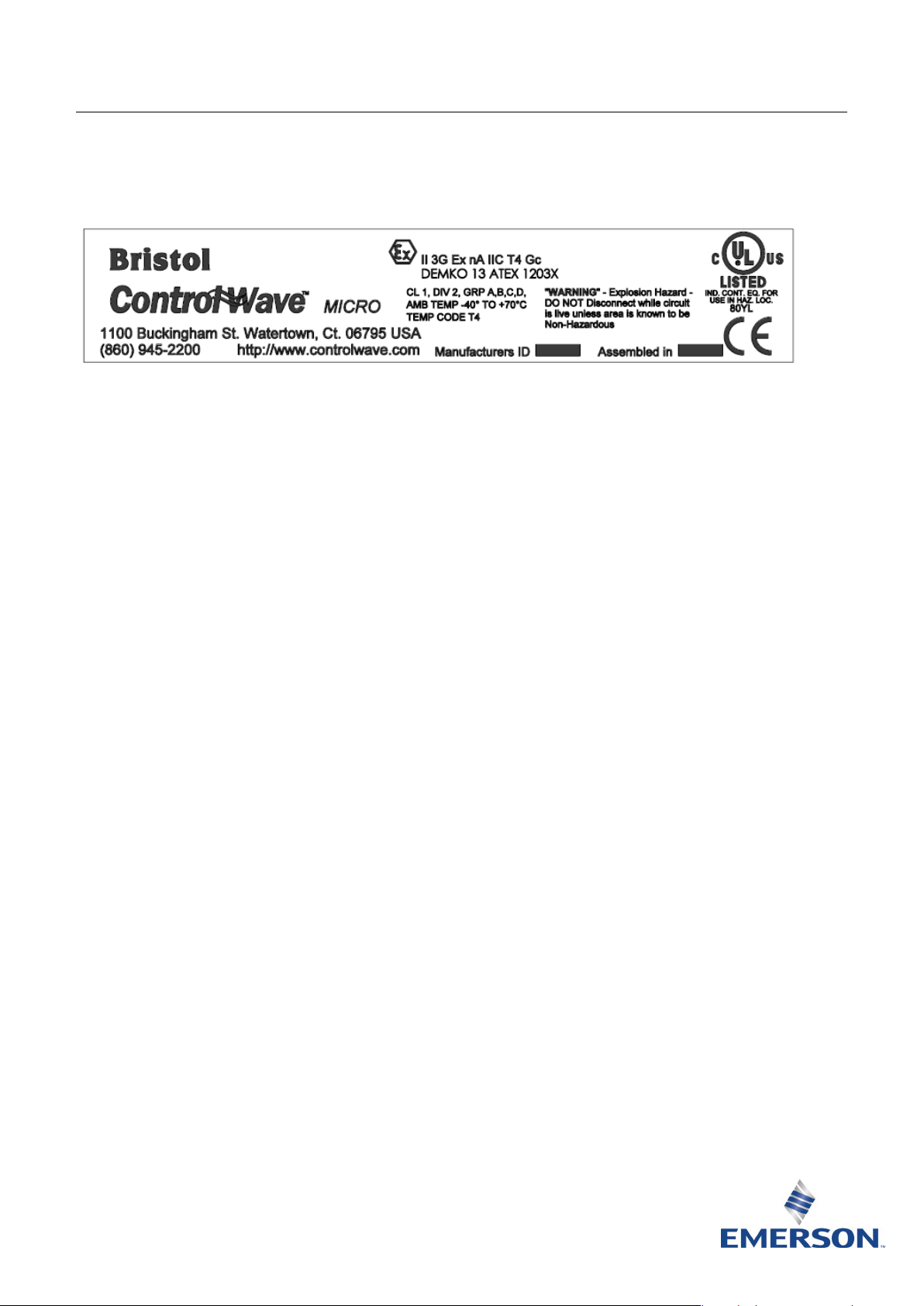
Base housing. Position as desired on the
enclosure mounting plate and locate mounting
holes on the plate using the ControlWave
Micro as a template. See Figure 2 for
dimensions. Drill and tap mounting holes in the
plate. Position the ControlWave Micro over the
tapped locations and attach to the plate with
four screws (not provided). Torque the screws
to approximately 1.1 to 1.4 N-m.
Safe Use Instructions – ControlWave Micro
Part D301761X012
June 2021
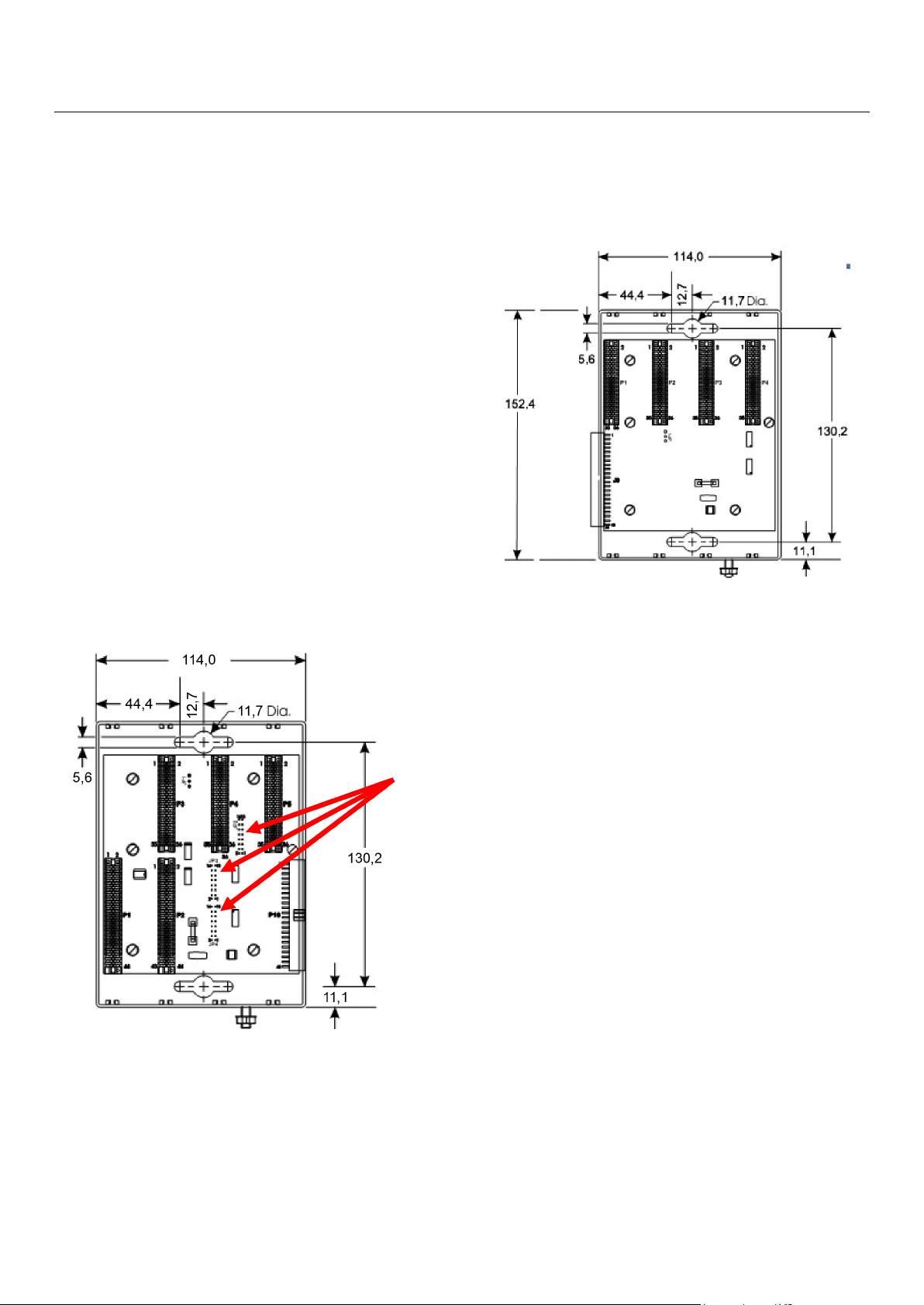
Figure 3. ControlWave Micro 4-Slot Expansion Housing
Dimensions (in millimeters)
Figure 2. ControlWave Micro 4-Slot Base Housing
Dimensions (in millimeters)
Expansion housing. Position the expansion
housing to the right of the base housing and
locate mounting holes using the expansion
housing as a template (see Figure 3 for
dimensions).
Note: Remove the paper label over the
connector on the right back edge of the
base housing to firmly attach the
expansion housing to the base housing.
Note: If you are attaching an expansion
housing to a 4-slot or 8-slot base
housing, remove the three bus
terminators (JP2, JP3, and JP4, shown on
Figure 2) from the backplane of the 4-slot
or 8-slot base housing.
Drill and tap holes in the mounting plate.
Position the base housing over the tapped
locations and attach to the plate with four
screws (not provided). Do
not fully tighten. Plug
the expansion housing into the base housing
and attach to the plate with four screws (not
provided). Torque the eight mounting screws to
approximately 1.1 to 1.4 N-m.
3. Find a suitable location for the enclosure assembly.
When choosing an installation site, be sure to
check all clearances. Provide adequate clearance
for wiring and service. Seal any holes placed in the
enclosure to maintain the IP54 enclosure rating.
Ensure the mounting of the assembly meets all
weight requirements and the installation conforms
to local building codes.
4. Properly ground the ControlWave Micro.
Properly grounding the Micro helps to reduce the
effects of electrical noise on the unit’s operation
and protects against lightning.
Base housings have a ground lug (see Figure 2) that
accommodates up to 5.19 mm (4 AWG) wire size.
After you install the base and any expansion housings
before you install any modules in the base or
and
expansion housings, you
must run a ground wire
between the base housing ground lug and a known
good earth ground. All earth grounds must have an
earth-to-ground rod or grid impedance of 2.0 ohms
www.Emerson.com/RemoteAutomation 3
Page 6

Safe Use Instructions – ControlWave Micro
Part D301761X012
June 2021
or less, as measured with a ground system tester. The
grounding conductor should have a resistance of 1
ohm or less between the ControlWave Micro’s
enclosure ground and the earth ground rod or grid.
Note: After you install the PSSM In the base
housing, run a 1.63 mm (14 AWG) wire
from the TB1-3 power connection (Ground)
to the same known good earth ground.
If the pipeline-to-earth impedance is greater than 2
ohms, electrically isolate the ControlWave Micro
and install a ground rod or grid grounding system.
The recommended cable for I/O signal wiring is an
insulated, shielded, twisted-pair. The twisted pair
and the shielding minimize signal errors caused by
EMI (electromagnetic interference), RFI (radio
frequency interference), and transients.
5. Install and configure the Power Supply/Sequencer
module (PSSM). Refer to the ControlWave Micro
Process Automation Controller Instruction Manual
(part D301392X012) for specific instructions on
configuring the PSSM to your site’s requirements.
6. Install and configure the CPU and communications
and I/O modules. Refer to the ControlWave Micro
Process Automation Controller Instruction Manual
(Part D301392X012) for specific instructions on
configuring these modules to your site’s
requirements.
7. Connect the ControlWave Micro to power, I/O
devices, and communication devices. The external
connections (or field terminals) are all located on
the termination board. The terminal block accepts
wires up to 1.63 mm (14 AWG) in size.
The ControlWave Micro connectors use
compression terminals. The input power
termination (IN+ / IN–) uses a removable connector
and accommodates wiring up to 1.63 mm (14
AWG) in size. In all cases, make connections by
baring the end (6 mm maximum) of the wire,
inserting the bared end into the clamp beneath the
termination screw, and then tightening the screw
to 0.25 N-m.
Notes:
Caution: Do not over-torque the connector
screws.
Check the input power polarity before you turn
on the power.
8. Apply power to the ControlWave Micro.
9. To place the ControlWave Micro in service, use
ControlWave Designer software to create a
ControlWave project that meets the needs of your
particular application. Download the project into
the unit. Then use the Flash Configuration utility to
set configuration parameters.
Note: For an overview of this process and
references to other relevant documentation,
see the ControlWave Micro Quick Setup Guide
(D301425X012).
10. If you are experiencing problems that appear to be
hardware-related, verify the wiring. If you still
experience problems, contact your local sales office
for return authorization.
11. To remove the ControlWave Micro from service:
Verify safe area.
Disconnect power from the unit.
Remove all external wiring connections.
Remove the FB107 from its enclosure.
12. Place the ControlWave Micro in a suitable
container for transportation or shipment.
The inserted wires should have a minimum of bare
wire exposed to prevent short circuits. Allow some
slack when making connections to prevent strain.
4 www.Emerson.com/RemoteAutomation
Page 7

Safe Use Instructions – ControlWave Micro
Global Headquarters,
North America, and Latin America:
end-user.
Europe:
Middle East/Africa:
Asia-Pacific:
T +65 6777 8211| F +65 6777 0947
Part D301761X012
June 2021
For customer service and technical support,
visit www.Emerson.com/SupportNet.
Emerson Automation Solutions
Remote Automation Solutions
6005 Rogerdale Road
Houston, TX 77072 U.S.A.
T +1 281 879 2699 | F +1 281 988 4445
www.Emerson.com/RemoteAutomation
Emerson Automation Solutions
Remote Automation Solutions
Unit 1, Waterfront Business Park
Dudley Road, Brierley Hill
Dudley, DY5 1LX UK
T +44 1384 487200
Emerson Automation Solutions
Remote Automation Solutions
Emerson FZE
P.O. Box 17033
Jebel Ali Free Zone – South 2
Dubai U.A.E.
T +971 4 8118100 | F +971 4 8865465
Emerson Automation Solutions
Remote Automation Solutions
1 Pandan Crescent
Singapore 128461
© 2014-2021 Remote Automation Solutions, a business unit of Emerson Automation
Solutions. All rights reserved.
This publication is for informational purposes only. While every effort has been made to ensure
accuracy, this publication shall not be read to include any warranty or guarantee, express or
implied, including as regards the products or services described or their use or applicability.
Remote Automation Solutions (RAS) reserves the right to modify or improve the designs or
specifications of its products at any time without notice. All sales are governed by RAS terms
and conditions which are available upon request. RAS accepts no responsibility for proper
selection, use or maintenance of any product, which remains solely with the purchaser and/or
Remote Automation Solutions
Page 8
Anleitung zur sicheren Verwendung – ControlWave Micro
Dok.-Nr. D301761X012
ControlWave® Micro ProzessautomatisierungsController
A
bbildung 1. Typenschild des ControlWave Micro (ATEX-Version abgebildet)
Di
ese Anleitung zur sicheren Verwendung ergänzt die
Betriebsanleitung für den ControlWave Micro
Prozessautomatisierungs-Controller (Dok.-Nr.
D301392X012) – ControlWave Micro Process Automation
Controller Instruction Manual. In diesem Handbuch finden
Sie ausführliche Warnungen, eine Installationsanleitung
und Verfahren zur Problemlösung.
Spezielle Voraussetzungen zur sicheren Verwendung des ControlWave Micro
Verbindungen mit den
Kommunikationsschnittstellen RS-232 oder
RS-485 müssen mechanisch mit passenden
Schraubverbindungen gesichert werden, um Lockern
oder Ablösen während des Betriebs zu verhindern.
Bei der Verwendung von Ethernet-Verbindungen
muss der RJ45-Stecker (Ethernet) mit ein
Gegenstecker mit passender Sicherungsklemme
ersehen sein, um Lockern bzw. Ablösen während des
v
Betriebs zu verhindern.
Der USB-Anschluss am IEC 62591-Modul darf nur
dann verwendet werden, wenn der Arbeitsbereich
nicht explosionsgefährdet (nicht entzündlich) ist.
Den ControlWave Micro in einem passenden, mit
Werkzeug zugänglichen Gehäuse mit ATEX- oder
IECEx-Zulassung und Schutzart IP54 oder höher
installieren.
Der Bereich, in dem das Gerät verwendet wird, muss
mindestens den Verschmutzungsgrad 2 gemäß IEC
60664-1 haben (d. h. die Umgebung darf kein
eitfähige Verschmutzung enthalten und das Gerät
l
muss in einem Innenraum oder geschützten Or
installiert werden).
Das Gerät kann in Zone 2 mit entzündlichen Gase
erwendet werden.
v
Das Gerät kann bei vorhandenen entzündlichen
asen und Dämpfen mit den Gerätegruppen IIC, IIB
G
oder IIA und mit Temperaturklassen T1, T2, T3 oder
T4 verwendet werden.
Das Gerät ist für die Verwendung bei
Umgebungstemperaturen im Bereich –40 °C ≤ T
Remote Automation Solutions
em
e
t
n
≤
amb
+70 °C
zertifiziert und darf nicht außerhalb diese
ereichs verwendet werden.
B
Das Gerät muss von entsprechend geschultem
Personal in Übereinstimmung mit den zutreffenden
Richtlinien (in der Regel IEC EN 60079-14) installiert
werden.
Für das Gerät ist kein Zusammenbau oder Zerlegen
erforderlich.
Hinsichtlich der Sicherheit ist eine Überprüfung des
korrekten Betriebs nicht erforderlich.
Es sind keine weiteren Einstellungen durch de
B
enutzer erforderlich.
Regelmäßige Inspektionen des Geräts sind von
entsprechend geschultem Personal in
Übereinstimmung mit den zutreffenden Richtlinien
uszuführen, um einen einwandfreien Zustand
a
sicherzustellen.
Es ist nicht vorgesehen, dass das Gerät vom Benutzer
repariert wird. Die Reparatur des Gerätes muss durch
Hersteller oder von ihm zugelassene Vertreter, in
den
Übereinstimmung mit den zutreffenden Richtlinien,
ausgeführt werden.
Das Gerät enthält keine durch den Benutzer
austauschbaren Ersatzteile.
Unter bestimmten extremen Umständen können die
nichtmetallischen Gehäuseteile dieses Gerätes ein
zü
ndfähige elektrostatische Ladung erzeugen. Darum
darf das Gerät nur mit einem feuchten Lappen
gereinigt werden.
Kommt das Gerät voraussichtlich mit aggressiven
Substanzen (wie z. B. sauren Flüssigkeiten oder
Gasen, die Metall angreifen können, oder
Lösungsmitteln, die Polymermaterial beschädigen
können) in Kontakt, so ist der Benutzer dafür
verantwortlich, geeignete Vorkehrungen zu treffen
d
ie einer Beeinträchtigung entgegenwirken, und so
sicherzustellen, dass die Schutzart nicht gefährdet ist.
Juni 2021
s
n
e
,
Page 9

Anleitung zur sicheren Verwendung – ControlWave Micro
TECHNISCHE DATEN
SPANNUNGSVERSORGUNG
UMGEBUNGSBEDINGUNGEN
Betriebstemperatur
Lagerungstemperatur
Luftfeuchtigkeit beim Betrieb
GEWICHT
ZULASSUNGEN
ATEX/IECEx
Dok.-Nr. D301761X012
Juni 2021
Es sollten Vorkehrungen getroffen werden, damit die
Nennspannung durch Überspannungsstörungen nicht
um mehr als 140 % der Nennspannung überschritten
wird.
Konformitätserklärung
Remote Automation Solutions erklärt hiermit, dass das
Produkt ControlWave Micro den grundlegenden
Anforderungen und anderen relevanten Vorschriften der
EU-Richtlinien 2004/108/EG (EMV) und 94/9/EG (ATEX)
entspricht.
GEFAHR
Wenn Geräte in einem explosionsgefährdeten Bereich
installiert werden, so muss darauf geachtet werden,
dass alle ausgewählten Installationskomponenten für
den Einsatz in solchen Bereichen zugelassen sind.
Installations- und Wartungsarbeiten dürfen nur dann
ausgeführt werden, wenn der Arbeitsbereich nicht in
einer explosionsgefährdeten Zone liegt.
Installationsarbeiten in einem explosionsgefährdeten
Bereich können zu Personen- und/oder zu Sachschäden
führen.
Vor der Verkabelung des ControlWave Micro muss
unbedingt die Stromzufuhr getrennt werden. Die
Verkabelung bei an die Spannungsversorgung
angeschlossenem Gerät kann zu Personen- und/oder
Sachschäden führen.
Externer Stromeingang: 10,7 bis 30 VDC (+12 VDC)
oder 21,7 bis 30 VDC (+24 VDC), je nach Konfiguration
von Steckbrücken, Schaltern, Verpolungsschutz
Eingang: 10,7 bis 30 VDC, max. 3 A, max. 36 Watt
Referenzklassen für jedes Gerät:
396560-01-6: 2 mA bei 3,3 VDC
396560-02-4: 2 mA bei 3,3 VDC
396563-16-3: 240 mA bei 3,3 VDC
396581-06-4: 145 mA bei 3,3 VDC
396657-02-8: 2 A bei 24 VDC
4 A bei 12 VDC
396686-01-0: 96 mA bei 120 VAC
40 mA bei 3,3 VDC
396897-02-9: 46 mA bei 3,3 VDC
24,3 mA bei Vext (11–30 VDC)
: –40 bis +70 °C
: –40 bis +85 °C
: 15 bis 95 %,
nichtkondensierend
0,36 kg (Basiseinheit mit 4 Steckplätzen oder
Erweiterungseinheit mit 4 Steckplätzen)
Um elektrische Schäden bei Arbeiten im Geräteinneren zu
vermeiden, müssen die erforderlichen
Vorsichtsmaßnahmen zur Vermeidung elektrostatischer
Entladungen eingehalten werden, zum Beispiel durch das
Tragen eines Antistatikbands.
Das Gehäuse nur öffnen, wenn der Arbeitsbereich nicht
explosionsgefährdet ist.
Bewertet gemäß folgenden europäischen Normen
(EMV):
EN 60079-0 (2012)
EN 60079-15 (2010)
th
IEC 60079-0 (6
IEC 60079-15 (4
Ed)
th
Ed)
DEMKO 13 ATEX 1203X
Produktkennzeichnungen für explosionsgefährdete
Umgebungen:
Ex nA IIC T4 Gc, –40 °C ≤ T
≤ +70 °C
amb
II 3 G.
Für Installation, Wartung sowie Störungsanalyse und
-beseitigung sind die folgenden Hilfsmittel bzw.
Werkzeuge erforderlich:
®
PC mit Microsoft
Windows® XP (mit Service Pack 3),
Windows 7, Windows 8, Windows 8.1 Pro oder
Windows 10 Pro.
ControlWave Designer-Software
Kreuzschlitzschraubendreher
Schlitzschraubendreher
1. Der ControlWave Micro wird in einem Karton geliefert.
Das Gerät aus dem Karton herausnehmen.
2 www.Emerson.com/RemoteAutomation
Page 10
Anleitung zur sicheren Verwendung – ControlWave Micro
und JP4
Frontseite
Frontseite
Dok.-Nr. D301761X012
Juni 2021
2. Für den ControlWave Micro gibt es drei
Basisgehäusekonfigurationen (mit 3, 4 und
8 Steckplätzen) und drei Erweiterungsgehäusekonfigurationen (mit 2, 4 und 8 Steckplätzen). Dieses
Dokument behandelt das Basisgehäuse mit 4
Steckplätzen und das Erweiterungsgehäuse mit
4 Steckplätzen. Weitere Informationen zu anderen
Gehäusen finden Sie in der Betriebsanleitung für den
ControlWave Micro ProzessautomatisierungsController (ControlWave Micro Process Automation
Controller Instruction Manual) (Dok.-Nr.
D301392X012). Den ControlWave Micro in einem
passenden ATEX- oder IECEx-zertifizierten Gehäuse mit
Schutzart IP54 oder höher entsprechend der
folgenden Anleitung installieren:
Basisgehäuse. Das Basisgehäuse wie gewünscht
auf der Gehäusemontageplatte positionieren und
unter Verwendung des ControlWave Micro als
Schablone die Montagebohrungen auf der Platte
ermitteln. Abmessungen siehe Abbildung 2.
Montagebohrungen mit einem Gewindebohrer in
der Platte anbringen. Den ControlWave Micro auf
die Gewindebohrungen setzen und mit vier
Schrauben (nicht im Lieferumfang enthalten)
befestigen. Die Schrauben mit einem
Drehmoment von etwa 1,1 bis 1,4 Nm anziehen.
Hinweis: Den Papieraufkleber auf dem Anschluss
an der rechten Hinterkante des
Basisgehäuses entfernen, um das
Erweiterungsgehäuse fest am
Basisgehäuse zu befestigen.
Abbildung 3. Abmessungen des ControlWave Micro-
Erweiterungsgehäuses mit 4 Steckplätzen (in Millimetern)
Steckbrücken
JP2, JP3
Abbildung 2. Abmessungen des ControlWave Micro-
Basisgehäuses mit 4 Steckplätzen (in Millimetern)
Erweiterungsgehäuse. Das Erweiterungsgehäuse
rechts neben dem Basisgehäuse positionieren und
die Montagebohrungen unter Verwendung des
Erweiterungsgehäuses als Schablone ermitteln
(Abmessungen siehe Abbildung 3).
Hinweis: Wenn ein Erweiterungsgehäuse an
einem Basisgehäuse mit 4 oder 8
Steckplätzen angebracht wird, die drei
Busabschlüsse (JP2, JP3 und JP4, siehe
Abbildung 2) an der Rückseite des
Basisgehäuses mit 4 oder 8 Steckplätzen
entfernen.
Montagebohrungen mit einem Gewindebohrer in
der Platte anbringen. Das Basisgehäuse auf die
Gewindebohrungen setzen und mit vier Schrauben
(nicht im Lieferumfang enthalten) auf der Platte
befestigen. Nicht vollständig anziehen. Das
Erweiterungsgehäuse in das Basisgehäuse
einstecken und mit vier Schrauben (nicht im
Lieferumfang enthalten) an der Platte befestigen.
Die acht Montageschrauben mit einem
Drehmoment von etwa 1,1 bis 1,4 Nm festziehen.
3. Einen geeigneten Standort für das Gehäuse suchen.
Bei der Auswahl eines Einbauortes alle Abstände
prüfen. Ausreichend Raum für die Kabel und für
Wartungstätigkeiten freilassen. Alle Löcher am
Gehäuse versiegeln, um die Schutzart IP54
beizubehalten. Sicherstellen, dass die Montage der
Baugruppe alle Gewichtsanforderungen erfüllt und die
Installation den lokalen Bauvorschriften entspricht.
4. Den ControlWave Micro sachgemäß erden.
Eine sachgemäße Erdung des Micro kann dazu
beitragen, Einflüsse durch elektrisches Rauschen auf
www.Emerson.com/RemoteAutomation 3
Page 11

Anleitung zur sicheren Verwendung – ControlWave Micro
Dok.-Nr. D301761X012
Juni 2021
den Gerätebetrieb zu minimieren, und schützt vor
Überspannungen/Blitzschlag.
Basisgehäuse verfügen über eine Erdungsklemme (siehe
Abbildung 2), die Kabel mit einem Durchmesser bis zu
5,19 mm (4 AWG) aufnehmen kann. Nach Installation
des Basisgehäuses und allen Erweiterungsgehäusen und
vor der Installation von Modulen im Basis- oder
Erweiterungsgehäuse muss ein Erdungskabel zwischen
der Erdungsklemme des Basisgehäuses und einer
zuverlässigen Erdung verlegt werden. Bei allen Erdungen
darf die Impedanz des Stabs bzw. des Netzes zwischen
Erdung und Masse maximal 2,0 Ohm betragen,
gemessen mit einem Erdungsprüfgerät. Der Erdleiter
sollte einen Widerstand von maximal 1,0 Ohm zwischen
der Gehäusemasse des ControlWave Micro und dem
Erdungsstab oder Erdungsnetz aufweisen.
Hinweis: Nach der Installation des Stromversorgungs-
/Sequenziermoduls (PSSM) ein Kabel mit
einem Durchmesser von 1,63 mm (14 AWG)
vom Stromanschluss TB1-3 (Masse) zur
gleichen Erdung verlegen.
Wenn die Impedanz zwischen Leitung und Erdung
über 2 Ohm liegt, eine elektrische Isolierung am
ControlWave Micro anbringen und ein Erdungssystem
mit Erdungsstab oder -netz installieren.
Für die E/A-Signale wird ein isoliertes, abgeschirmtes,
verdrilltes Doppelkabel empfohlen. Durch die Verdrillung
und die Abschirmung werden Signalfehler durch EMS
(elektromagnetische Störung), RFI (Funkstörung) und
Transienten minimiert.
5. Das Stromversorgungs-/Sequenziermodul (PSSM)
installieren und konfigurieren. Genaue Anweisungen
zur Einrichtung des PSSM entsprechend den
Bedürfnissen Ihres Standorts finden Sie in der
Betriebsanleitung für den ControlWave Micro
Prozessautomatisierungs-Controller (ControlWave
Micro Process Automation Controller Instruction Manual)
(Dok.-Nr. D301392X012).
6. Die CPU, Kommunikations- und E/A-Module
installieren und konfigurieren. Genaue Anweisungen
zur Einrichtung dieser Module gemäß den
Bedürfnissen Ihres Standorts finden Sie in der
Betriebsanleitung für den ControlWave Micro
Prozessautomatisierungs-Controller (ControlWave
Micro Process Automation Controller Instruction Manual)
(Dok.-Nr. D301392X012).
7. Den ControlWave Micro mit dem Stromnetz, E/AGeräten und Kommunikationsgeräten verbinden. Die
externen Anschlüsse (oder Feldanschlüsse) befinden
sich alle an der Anschlussplatine. Die Klemmleiste ist
für einen Durchmesser bis zu 1,63 mm (14 AWG)
geeignet.
Die Anschlüsse des ControlWave Micro sind
Schraubklemmen. Der Anschluss für den
Eingangsstrom (IN+/IN–) verwendet einen
beweglichen Stecker und ist für Kabel mit einem
Durchmesser bis zu 1,63 mm (14 AWG) geeignet. Für
den Anschluss immer das Kabelende abisolieren
(maximal 6 mm), in die Klemme unter die
Klemmschraube einführen und die Schraube dann mit
einem Drehmoment von 0,25 Nm festziehen.
Um Kurzschlüsse zu vermeiden, sollten die Adern der
eingeführten Kabel so kurz wie möglich abisoliert sein.
Bei der Herstellung von Verbindungen auf
Zugentlastung achten.
Hinweise:
Achtung: Die Klemmenschrauben nicht zu fest
anziehen.
Vor dem Einschalten der Spannungsversorgung die
Polarität des Eingangsstroms prüfen.
8. Die Stromversorgung des ControlWave Micro
einschalten.
9. Um den ControlWave Micro in Betrieb zu nehmen, mit
der ControlWave Designer-Software ein ControlWaveProjekt erstellen, das den Anforderungen der
jeweiligen Anwendung entspricht. Das Projekt in das
Gerät laden. Dann mit dem Dienstprogramm „Flash
Configuration“ die Konfigurationsparameter
einstellen.
Hinweis: Einen Überblick über diesen Vorgang und
Referenzen zu anderer relevanter
Dokumentation finden Sie in der
Kurzanleitung für den ControlWave Micro
(ControlWave Micro Quick Setup Guide)
(D301425X012).
10. Falls Probleme auftreten, deren Ursache in der
Hardware vermutet wird, die Verkabelung prüfen. Falls
die Probleme weiterhin bestehen, wenden Sie sich an
Ihr lokales Vertriebsbüro, um eine
Rückgabegenehmigung zu erhalten.
11. So nehmen Sie den ControlWave Micro aus dem
Betrieb:
Prüfen, dass der Bereich sicher ist.
Die Stromversorgung vom Gerät trennen.
Alle externen Kabelanschlüsse entfernen.
Den FB107 aus dem Gehäuse herausnehmen.
12. Den ControlWave Micro in einen geeigneten Behälter
für den Transport oder Versand legen.
4 www.Emerson.com/RemoteAutomation
Page 12

Anleitung zur sicheren Verwendung – ControlWave Micro
Weltweite Firmenzentrale
Nordamerika/Lateinamerika:
Endanwender.
Europa:
Naher Osten/Afrika:
Asien/Pazifik:
Tel.: +65 6777 8211| Fax: +65 6777 0947
Doc-Nr. D301761X012
Juni 2021
Kundendienst und technische Unterstützung
finden Sie unter www.Emerson.com/SupportNet.
Emerson Automation Solutions
Remote Automation Solutions
6005 Rogerdale Road
Houston, TX 77072, USA
Tel.: +1 281 879 2699 | Fax: +1 281 988 4445
www.Emerson.com/RemoteAutomation
Emerson Automation Solutions
Remote Automation Solutions
Unit 1, Waterfront Business Park
Dudley Road, Brierley Hill
Dudley DY5 1LX UK
Tel.: +44 1384 487200
Emerson Automation Solutions
Remote Automation Solutions
Emerson FZE
P.O. Box 17033
Jebel Ali Free Zone – South 2
Dubai, Vereinigte Arabische Emirate
Tel.: +971 4 8118100 | Fax: +971 4 8865465
Emerson Automation Solutions
Remote Automation Solutions
1 Pandan Crescent
Singapur 128461
© 2017-2021 Remote Automation Solutions, ein Geschäftsbereich von Emerson
Automation Solutions. Alle Rechte vorbehalten.
Diese Publikation dient nur zu Informationszwecken. Obwohl große Sorgfalt zur
Gewährleistung ihrer Exaktheit aufgewendet wurde, kann diese Publikation nicht zur
Ableitung von Garantie- oder Gewährleistungsansprüchen, ob ausdrücklicher Art oder
stillschweigend, hinsichtlich der in dieser Publikation beschriebenen Produkte oder
Dienstleistungen oder ihres Gebrauchs oder ihrer Verwendbarkeit herangezogen werden.
Remote Automation Solutions (RAS) behält sich das Recht vor, jederzeit und ohne
Vorankündigung die Konstruktion und technischen Daten seiner Produkte zu ändern oder
zu verbessern. Für alle Verkäufe gelten unsere (RAS) allgemeinen Geschäftsbedingungen,
die auf Anfrage zur Verfügung gestellt werden. Die Verantwortung bezüglich der richtigen
Auswahl, Verwendung oder Wartung von jeglichen Produkten liegt allein beim Käufer und
Remote Automation Solutions
Page 13

6 www.Emerson.com/RemoteAutomation
Page 14

Consignes de sécurité – ControlWave Micro
Contrôleur d’automatisation des procédés ControlWave® Micro
Figure 1. Étiquette ControlWave Micro (Version ATEX illustrée)
ilisez les présentes consignes avec le Manuel
Ut
d’instruction du contrôleur d’automatisation des
procédés ControlWave Micro (réf. D301392X012).
Consultez ce manuel pour obtenir toutes les mesures
de précaution, explications d’installation et
procédures de dépannage.
Conditions spéciales pour une utilisation en toute sécurité de ControlWave Micro
Les branchements effectués avec les ports de
ommunication RS-232 ou RS-485 doivent être
c
fixés et sécurisés mécaniquement avec de
raccords vissés appropriés pour éviter tout
desserrage ou déconnexion pendant l’utilisation.
Lors de l’utilisation de branchements Ethernet, l
b
ranchement (Ethernet) RJ45 doit posséder un
connecteur homologue avec une pince d’attache
valide pour éviter tout desserrage ou déconnexion
pendant l’utilisation.
Le connecteur USB sur le module CEI 62591 ne
doit être utilisé que s’il est certain que la zone
d’utilisation n’est pas une zone dangereuse (noninflammable).
Installez le ControlWave Micro dans un coffret
accessible avec des outils, de catégorie IP54 ou
supérieure et approuvé par la règlementation
ATEX ou IECEx.
La zone où l’équipement sera utilisé devra être un
environnement de degré de pollution 2 minimum,
tel que défini par la norme CEI 60664-1
(l’environnement ne devra pas être pollué par des
éléments conducteurs et l’équipement devra êtr
nstallé à l’intérieur ou dans un endroit abrité).
i
L’équipement peut être utilisé dans des
environnements de type 2 avec des ga
i
nflammables.
L’équipement peut être utilisé en présence de gaz
ou vapeurs inflammables avec les groupes IIC, IIB
et IIA et avec les classes de température T1, T2, T3
ou T4.
s
e
z
e
L’équipement est homologué pour une utilisation
à des températures ambiantes comprises entre 40 °C ≤ T
de cette plage de températures.
L’installation de l’équipement doit être effectu
p
ar un personnel qualifié selon les règles et usage
en vigueur (généralement CEI EN 60079-14).
L’équipement ne requiert ni assemblage ni
démontage.
En matière de sécurité, il n’est pas nécessaire de
vérifier son bon fonctionnement.
Aucun réglage utilisateur n’est requis.
L’inspection périodique et régulière de
l’équipement doit être effectuée par un personnel
qualifié selon les règles et usages en vigueur pour
assurer qu’il est maintenu dans un état
satisfaisant.
Il n’est pas prévu que l’utilisateur répare
équipement. La réparation de l’équipement doit
l’
être effectuée par le fabricant ou ses agents
agréés selon les règles et usages en vigueur.
L’équipement ne contient aucune pièce
emplaçable par le client.
r
Sous certaines circonstances extrêmes, les partie
n
on métalliques incorporées dans le coffret de cet
équipement peuvent générer un niveau de charge
lectrostatique suffisant à un allumage. C’est pour
é
cela que l’équipement ne doit être nettoy
qu’avec un chiffon humide.
Si l’équipement est susceptible d’entrer en
contact avec des substances agressives (tels que
des liquides acides ou des gaz pouvant attaquer
les métaux ou des solvants susceptibles d’affecter
les matériaux polymères), l’utilisateur doit
prendre les précautions nécessaires afin
d’empêcher tout dommage à l’équipement qui
risquerait de remettre en cause le type d
p
rotection.
≤ +70 °C et ne doit pas être utilisé hors
amb
réf. D301761X012
Juin 2021
ée
s
s
é
e
Remote Automation Solutions
Page 15

Consignes de sécurité – ControlWave Micro
SPÉCIFICATIONS
ALIMENTATION
Entrée d’alimentation externe
Entrée :
CONDITIONS AMBIANTES
Température ambiante de fonctionnement :
Température de stockage :
Humidité relative de fonctionnement :
POIDS
CERTIFICATIONS
ATEX/IECEx
réf. D301761X012
Juin 2021
Les dispositions nécessaires devront être prises
afin de s’assurer que les surtensions transitoires ne
soient pas supérieures de 140 % de la tension
nominale.
Déclaration de conformité
Par la présente, Remote Automation Solutions déclare
que le produit ControlWave Micro est conforme aux
exigences essentielles et autres provisions applicables
des directives européennes 2004/108/CE (CEM) et
94/9/CE (ATEX).
DANGER
Si les unités sont installées dans une zone
dangereuse, assurez-vous que les étiquettes des
composants sélectionnés autorisent leur usage dans
une telle zone. L’installation et la maintenance ne
doivent être effectuées que lorsque la zone ne
présente aucun risque. L’installation dans une zone
dangereuse peut entraîner des blessures ou des
dégâts matériels.
Mettez toujours le ControlWave Micro hors tension
avant d’effectuer tout type de câblage. Toute
intervention sur un équipement sous tension
pourrait entraîner des blessures ou des dégâts
matériels.
Pour éviter d’endommager les circuits lors d’une
intervention à l’intérieur de l’unité, appliquer les
précautions pertinentes concernant les décharges
électrostatiques, notamment le port d’un bracelet
antistatique.
N’ouvrez pas le coffret, sauf s’il est certain que la zone
ne présente aucun risque.
: 10,7 à 30 Vcc (+12 Vcc) ou
21,7 à 30 Vcc (+24 Vcc), en fonction de la configuration des
interrupteurs de cavaliers, inversez la protection de polarité
10,7 à 30 Vcc, 3 A max, 36 W max
Les régimes nominaux de référence pour chaque
appareil sont :
396560-01-6 : 2 mA à 3,3 Vcc
396560-02-4 : 2 mA à 3,3 Vcc
396563-16-3 : 240 mA à 3,3 Vcc
396581-06-4 : 145 mA à 3,3 Vcc
396657-02-8 : 2 A à 24 Vcc
4 A à 12 Vcc
396686-01-0 : 96 mA à 120 Vcc
40 mA à 3,3 Vcc
396897-02-9 : 46 mA à 3,3 Vcc
24,3 mA à Vext (11-30 Vcc)
-40 à +70 °C
-40 à +85 °C
15 à 95 %, sans
condensation
0,36 kg (unité de base à 4 emplacements ou unité
d’expansion à 4 emplacements)
Evalué selon les normes suivantes :
EN 60079-0 (2012)
EN 60079-15 (2010)
CEO 60079-0 (6
CEI 60079-15 (4
DEMKO 13 ATEX 1203X
Marquages du produit pour les zones dangereuses :
Ex nA IIC T4 Gc, -40 °C ≤ T
e
Ed)
e
Ed)
≤ +70 °C
amb
2 www.Emerson.com/RemoteAutomation
II 3 G.
Les outils suivants sont nécessaires pour l’installation,
la maintenance et le dépannage :
®
Ordinateur PC exécutant Microsoft
Windows® XP
(avec Service Pack 3), Windows 7, Windows 8,
Windows 8.1 Pro ou Windows 10 Pro.
Logiciel ControlWave Designer
Tournevis cruciforme
Tournevis à tête plate
1. Le ControlWave Micro vous est livré dans un carton.
Retirez-le de l’emballage.
2. Le ControlWave Micro comprend trois
configurations de boîtier de base (3 emplacements,
4 emplacements et 8 emplacements) et trois
configurations de boîtier d’expansion
(2 emplacements, 4 emplacements, et
8 emplacements). Ce document présente le boîtier
Page 16

de base à 4 emplacements et le boîtier d’expansion
Avant
Avant
à 4 emplacements. Pour plus de renseignements
sur les autres boîtiers, consultez le Manuel
d’instruction du contrôleur d’automatisation des
procédés ControlWave Micro (réf. D301392X012).
Installez le ControlWave Micro dans un coffret IP54
ou supérieur, approuvé par la règlementation ATEX
ou IECEx, en suivant les instructions suivantes :
Boîtier de base. Positionnez comme souhaité
sur la plaque de montage et repérez
l’emplacement des orifices de fixation sur la
plaque en utilisant le ControlWave Micro
comme modèle. Voir Figure 2 pour les
dimensions. Percez et taraudez les orifices de
fixation dans la plaque. Positionnez le
ControlWave Micro au-dessus des
emplacements taraudés et fixez-le à la plaque
avec 4 vis (non fournies). Serrez les vis au
couple de 1,1 à 1,4 N.m environ.
Consignes de sécurité – ControlWave Micro FB3000 RTU
réf. D301761X012
Juin 2021
Figure 3. Dimensions du boîtier d’extension à
4 emplacements ControlWave Micro (en millimètres)
Figure 2. Dimensions du boîtier de base à
4 emplacements ControlWave Micro (en millimètres)
Boîtier d’extension. Positionnez le boîtier
d’extension à la droite du boîtier de base et
repérez l’emplacement des orifices de fixation
en utilisant le boîtier d’extension comme
modèle (voir Figure 3 pour les dimensions).
Remarque : enlevez l’étiquette en papier située
sur le connecteur sur le bord arrière
droit du boîtier de base pour fixer
fermement le boîtier d’extension au
boîtier de base.
Cavaliers
JP2, JP3
et JP4
Remarque : en cas de fixation d’un boîtier
d’expansion à un boîtier de base à 4
ou 8 emplacements, déposez les
trois terminaisons de bus (JP2, JP3
et JP4 illustrés Figure 2) de la face
arrière du boîtier de base.
Percez et taraudez les orifices dans la plaque de
montage. Positionnez le boîtier de base audessus des emplacements taraudés et fixez-le à
la plaque avec 4 vis (non fournies). Ne serrez
complètement. Branchez le boîtier d’extension
dans le boîtier de base et fixez-le à la plaque
avec 4 vis (non fournies). Serrez les huit vis de
fixation entre 1,1 et 1,4 N.m environ.
3. Trouvez un emplacement convenable pour
l’ensemble du coffret. Lors du choix d’un
emplacement, assurez-vous de bien vérifier tous les
dégagements. Veillez à laisser un espace suffisant
pour le câblage et l’entretien. Scellez tous les
orifices situés dans le coffret pour garantir sa
classification IP54. Assurez-vous que le montage de
l’ensemble satisfait aux exigences de poids et que
l’installation est conforme aux codes du bâtiment
locaux.
4. Mettez correctement à la terre le ControlWave
Micro.
La mise à la terre correcte du Micro permet de
réduire les effets de bruit électrique lors du
fonctionnement de l’unité et protège contre la
foudre.
Les boîtiers de base possèdent un plot de masse (voir
Figure 2) qui peut recevoir des fils mesurant jusqu’à
5,19 mm. Après avoir installé le boîtier de base et
tout boîtier d’expansion, et avant d’installer tout
pas
www.Emerson.com/RemoteAutomation 3
Page 17

Consignes de sécurité – ControlWave Micro
réf. D301761X012
Juin 2021
module, vous devez acheminer un câble de mise à la
terre entre du boîtier de base et une bonne prise de
terre. Toutes les prises de terre doivent posséder une
tige de mise à la terre ou une grille d’impédance de
2,0 ohms ou moins, à mesurer avec un testeur de
système de mise à la terre. Le conducteur de mise à la
terre doit posséder une résistance de 1 ohm ou
moins entre la prise de terre du coffret du
ControlWave Micro et la grille ou la tige de mise à la
terre.
Remarque : après avoir installé le PSSM dans le
boîtier de base, acheminez un fil de
1,63 mm du branchement de
l’alimentation TB1-3 (masse) vers la
même bonne prise de terre.
Si l’impédance de la conduite vers la terre est
supérieure à 2 ohms, isolez électriquement le
ControlWave Micro et installez une tige de mise à la
terre ou un système de grille de mise à la terre.
Il est recommandé que le câble des signaux
d’entrée et de sortie soit isolé, blindé et à paire
torsadée. La paire torsadée et le blindage
minimisent les erreurs de signal causées par
l’interférence électromagnétique, les perturbations
radioélectriques et les transitoires.
5. Installez et configurez le module
d’alimentation/séquenceur (PSSM). Consultez le
Manuel d’instruction du contrôleur d’automatisation des
procédés ControlWave Micro (réf. D301392X012), pour
obtenir des instructions spécifiques concernant la
configuration du PSSM répondant aux exigences de
votre emplacement.
6. Installez et configurez l’unité centrale et les
modules de communications et d’entrée et sortie
(E/S). Consultez le Manuel d’instruction du
contrôleur d’automatisation des procédés
ControlWave Micro (réf. D301392X012), pour
obtenir des instructions spécifiques concernant la
configuration de ces modules répondant aux
exigences de votre emplacement.
7. Branchez le ControlWave Micro à une source
d’alimentation, aux appareils E/S et aux appareils
de communication. Les connexions externes (ou
bornes de secteur) sont toutes situées sur le
tableau de bornes. Le bloc de jonction accepte les
fils d’une taille maximale de 1,63 mm.
Les connecteurs du ControlWave Micro utilisent
des bornes de compression. La borne d’entrée
d’alimentation (IN+/IN-) utilise un connecteur
amovible et peut recevoir des fils jusqu’à 1,63 mm.
Dans tous les cas, effectuez les connexions en
dénudant l’extrémité (6 mm maximum) du fil, en
insérant l’extrémité dénudée dans le collier près de
la vis de raccordement, puis en serrant la vis à
0,25 N.m.
Les fils insérés doivent avoir une partie minimale
exposée de fil dénudé pour éviter les courtscircuits. Ne pas tendre excessivement les fils pour
éviter toute tension.
Remarque :
Attention : ne serrez pas les vis du connecteur de
façon excessive.
Vérifiez la polarité de l’entrée d’alimentation
avant de mettre sous tension.
8. Mettez le ControlWave Micro sous tension.
9. Pour mettre le ControlWave Micro en service,
utilisez le logiciel ControlWave Designer pour créer
un projet ControlWave répondant à vos besoins
spécifiques. Téléchargez le projet dans l’unité.
Ensuite, utilisez l’utilitaire Flash Configuration pour
régler les paramètres de configuration.
Remarque : pour obtenir une vue d’ensemble de ce
processus et vous référer à d’autres
documents pertinents, consultez le
Guide condensé ControlWave Micro (réf.
D301425X012).
10. En cas de problèmes qui semblent liés au matériel,
vérifiez le câblage. Si les problèmes persistent,
contactez votre bureau de vente local pour
l’autorisation de retour.
11. Pour retirer du service le ControlWave Micro :
Vérifiez que la zone est sûre.
Mettez l’unité hors tension.
Retirez tous les branchements de fils externes.
Retirez le FB107 de son coffret.
12. Placez le ControlWave Micro dans un conteneur
approprié pour le transport ou l’expédition.
4 www.Emerson.com/RemoteAutomation
Page 18

Consignes de sécurité – ControlWave Micro FB3000 RTU
Siège social international
Amérique du Nord et Amérique latine :
Cette publication est à titre informatif uniquement. Bien que tous les efforts aient été faits pour
l'entretien d'un produit, laquelle incombe uniquement à l'acquéreur ou à l'utilisateur final.
Europe :
Moyen-Orient/Afrique :
Asie-Pacifique :
T +65 6777 8211| F +65 6777 0947
réf. D301761X012
Juin 2021
Pour contacter le service clientèle et bénéficier d'une assistance technique,
consultez la page www.Emerson.com/SupportNet.
Emerson Automation Solutions
Remote Automation Solutions
6005 Rogerdale Road
Houston, TX 77072 États-Unis.
T +1 281 879 2699 | F +1 281 988 4445
www.Emerson.com/RemoteAutomation
Emerson Automation Solutions
Remote Automation Solutions
Unit 1, Waterfront Business Park
Dudley Road, Brierley Hill
Dudley DY5 1LX UK
T +44 1384 487200
Emerson Automation Solutions
Remote Automation Solutions
Emerson FZE
P.O. Box 17033
Jebel Ali Free Zone – South 2
Dubai, Émirats Arabes Unis.
T +971 4 8118100 | F +971 4 8865465
Emerson Automation Solutions
Remote Automation Solutions
1 Pandan Crescent
Singapour 128461
© 2014-2021 Remote Automation Solutions, une division d'Emerson Automation Solutions.
Tous droits réservés.
vérifier l'exactitude des informations présentées dans ce document, ce dernier ne saurait être
considéré comme une garantie tacite ou explicite des produits ou services décrits quant à leur
utilisation ou leur applicabilité. Remote Automation Solutions (RAS) se réserve le droit de
modifier ou d'améliorer les conceptions ou les spécifications de ses produits à tout moment et
sans préavis. Toutes les ventes sont régies par les conditions générales de RAS, lesquelles sont
disponibles sur demande. RAS décline toute responsabilité quant au choix, à l'utilisation ou à
Remote Automation Solutions
Page 19

Instruções para uso seguro – ControlWave Micro
ControlWave® - Controlador de automação de processo
Figura 1. Placa ControlWave Micro (versão ATEX mostrada)
Peça D301761X012
Junho de 2021
Use este documento de instruções para um uso seguro
(SUI) juntamente com o Manual de instruções do
controlador de automação de processo ControlWave
Micro (peça D301392X012). Para obter todos os
cuidados e descrições relacionados aos procedimentos
de instalação e solução de problemas, consulte o
manual.
Condições especiais para uso seguro do ControlWave Micro
As conexões feitas com as portas de comunicação
RS-232 e RS-485 devem estar mecanicament
f
ixadas a conexões com parafusos adequados,
para evitar a perda ou a desconexão durante o
uso.
Para usar conexões Ethernet, a conexão RJ
(E
thernet) deve ter um conector acoplado a um
clipe de fixação válido, para evitar a perda ou
esconexão durante o uso.
d
O conector USB do módulo IEC 62591 não dever
se
r usado, a menos que se saiba que o local não é
perigoso (não inflamável).
Instale o ControlWave Micro com uma ferramenta
para invólucro adequada, com certificação ATEX
ou IECEX IP54 ou superior.
O local em que o equipamento é usado deve ter
um grau mínimo de poluição 2, conforme
definição do IEC 60664-1 (ou seja, o ambiente não
deve conter poluição condutora e o equipament
d
everá ser instalado em um local interno ou
protegido).
O equipamento pode ser usado dentro da zona 2
om gases inflamáveis.
c
O equipamento pode ser usado com gases
inflamáveis e vapores, grupos de equipamento
IIC, IIB ou IIA e classes de temperaturas T1, T2, T3
u T4.
o
O equipamento é certificado para uso em
temperatura ambiente, com variação entre -40°C
≤ +70°C e não deverá ser usado fora destes
≤ T
amb
ites.
lim
e
45
a
á
o
s
O equipamento deverá ser instalado por pessoa
de
vidamente treinadas, em conformidade com
código de prática vigente (normalmente, o IEC EN
60079-14).
Não é necessário montar nem desmontar o
equipamento.
Não é necessário verificar se o equipament
f
unciona corretamente em relação à segurança.
Não é necessário fazer ajustes para usuários.
Uma inspeção regular periódica no equipamento
deverá ser realizada por pessoas devidamente
treinadas, em conformidade com o código de
prática vigente, para assegurar uma manutenção
em condições satisfatórias.
O equipamento não deverá ser reparado pelo
usuário. O reparo do equipamento deverá ser feito
pelo fabricante ou agentes treinados pelo mesmo,
em conformidade com o código de prática
vigente.
O equipamento não contém peças que possam
ser substituídas pelo cliente.
Em determinadas circunstâncias extremas, as peças
não metálicas incorporadas no invólucro deste
equipamento podem gerar um nível de ignição
suscetível a carga eletrostática. Portanto, a limpeza
do equipamento deverá ser feita apenas com um
pano úmido.
Se houver probabilidade de um contato do
equipamento com substâncias agressivas (como
líquidos ácidos ou gases que possam atacar metais,
ou solventes que possam afetar materiais
poliméricos), é responsabilidade do usuário tomar
os cuidados necessários para evitar que o
equipamento seja afetado negativamente,
garantindo, assim, que o tipo de proteção não seja
comprometido.
Providências devem ser tomadas para evitar que
tensão nominal seja excedida por perturbações
ransitórias em mais de 140%.
t
s
o
o
a
Remote Automation Solutions
Page 20

Instruções para uso seguro – ControlWave Micro
ESPECIFICAÇÕES
ENERGIA
Entrada de alimentação externa:
Entrada:
AMBIENTAIS
Temperatura ambiente operacional:
Temperatura de armazenamento:
Umidade operacional:
PESO
CERTIFICAÇÕES
ATEX/IECEx
Peça D301761X012
Junho de 2021
Declaração de conformidade
Por este documento, a Remote Automation Solutions
declara que o produto ControlWave Micro está em
conformidade com os requisitos fundamentais e
outras cláusulas pertinentes das Diretivas Europeias
2004/108/CE (EMC) e 94/9/CE (ATEX).
PERIGO
Para instalar unidades em um local perigoso,
verifique se todos os componentes selecionados
para instalação têm etiqueta para uso nestes locais.
A instalação e a manutenção só devem ser realizadas
quando se tem conhecimento que a área não é
classificada. A instalação em um local perigoso pode
causar lesão pessoal ou danos à propriedade.
Sempre desligue a alimentação do ControlWave
Micro, antes de experimentar qualquer tipo de
fiação. A fiação de um equipamento ligado pode
causar lesão pessoal ou danos à propriedade.
Para evitar danos ao circuito ao trabalhar dentro da
unidade, tome os cuidados necessários com a
descarga eletrostática, tais como usar uma pulseira de
aterramento.
10,7 a 30 V cc (+12 V cc) ou
21,7 a 30 V cc (+24 V cc), de acordo com a configuração dos
switches jumpers e da proteção da polaridade reversa
10,7 a 30 V cc, 3A máx., 36 watts máx
As classificações de referência para cada dispositivo são:
396560-01-6: 2 mA @ 3,3 V cc
396560-02-4: 2 mA @ 3,3 V cc
396563-16-3: 240 mA @ 3,3 V cc
396581-06-4: 145 mA @ 3,3 V cc
396657-02-8: 2A @ 24 V cc
4A @ 12 V cc
396686-01-0: 96 mA @ 120 V ca
40 mA@ 3,3 V cc
396897-02-9: 46 mA @ 3,3 V cc
24,3 mA @ Vext (11-30 V cc)
-40 a +70°C
-40 a +85°C
15 a 95%, sem condensação
0,36 kg (unidade básica com 4 slots ou unidade de expansão
com 4 slots)
Não abra o invólucro, a menos que você saiba que o
local não é perigoso.
A avaliação é feita conforme as normas abaixo:
EN 60079-0 (2012)
EN 60079-15 (2010)
IEC 60079-0 (6
IEC 60079-15 (4
DEMKO 13 ATEX 1203X
Marcação de produtos para áreas classificadas:
Ex dentro da IIC T4 Gc, -40°C ≤ T
a
Ed)
a
Ed)
II 3 G.
≤+70°C
amb
As ferramentas abaixo são necessárias para a
instalação, a manutenção e a solução de problemas:
®
Computador pessoal com Microsoft
Windows®
XP (com Service Pack 3), Windows 7, Windows 8,
Windows 8.1 Pro ou Windows 10 Pro instalado.
Software ControlWave Designer.
Chave de fenda Phillips.
Chave de fenda simples.
1. Você recebe o ControlWave Micro em uma caixa.
Retire-o da caixa.
2 www.Emerson.com/RemoteAutomation
Page 21

2. O ControlWave Micro tem três configurações do
Jumpers
JP2, JP3 e
JP4
Frente
Frente
invólucro de base (3 slots, 4 slots e 8 slots) e três
configurações do invólucro de expansão (2 slots, 4
slots e 8 slots). Este documento é sobre o invólucro
base com 4 slots e o invólucro de expansão com 4
slots. Para mais informações sobre outros
invólucros, consulte o Manual do controlador de
automação de processo ControlWave Micro
(D301392X012). Instale o ControlWave Micro em
um invólucro com certificação ATEX ou IECEX IP54
ou superior adequado, da seguinte maneira:
Invólucro de base. Posicione-o, como
desejado, dentro da placa de montagem do
invólucro e localize os furos de montagem da
placa, usando o ControlWave Micro como
modelo. Consulte a Figura 2 para saber as
dimensões. Perfure e cubra os orifícios dentro
da placa de montagem. Coloque o
ControlWave Micro sobre os orifícios cobertos
e prenda-o à placa com quatro parafusos (não
fornecidos). Aperte os parafusos com torque
de aproximadamente 1,1 a 1,4 N-m.
Instruções para uso seguro – ControlWave Micro
Peça D301761X012
Junho de 2021
Figura 3. Dimensões do invólucro de expansão com 4
slots do ControlWave Micro (em milímetros)
Nota: Se você estiver prendendo um invólucro
de expansão a um invólucro de base com
4 ou 8 slots, retire as três terminações de
barramento (JP2, JP3 e JP4, mostradas
dentro da Figura 2) do backplane do
invólucro de base com 4 ou 8 slots.
Figura 2. Dimensões do invólucro de base com 4 slots do
ControlWave Micro (em milímetros)
Invólucro de expansão. Posicione o invólucro
de expansão à direita do invólucro de base e
localize os orifícios de montagem, usando o
invólucro de expansão como modelo (consulte
a Figura 3 para conhecer as dimensões).
Perfure e cubra os orifícios dentro da placa de
montagem. Coloque o invólucro de base sobre
os orifícios cobertos e prenda-o à placa com
quatro parafusos (não fornecidos).
completamente. Conecte o invólucro de
expansão ao invólucro de base e prenda-o à
placa com quatro parafusos (não fornecidos).
Aperte os oito parafusos com torque de
aproximadamente 1,1 a 1,4 N-m.
3. Encontre um local adequado para o conjunto do
invólucro. Antes de escolher um local de instalação,
verifique todos os espaços livres. Forneça espaço
livre adequado para a fiação e para a manutenção.
Sele todos os orifícios colocados no invólucro para
manter a categoria de proteção IP54. Verifique se a
montagem do conjunto preenche todos os
requisitos de peso e se a instalação está em
conformidade com os códigos de construção
locais.
4. Aterre o ControlWave Micro corretamente.
O aterramento correto do Micro ajuda a reduzir os
efeitos do ruído elétrico durante a operação da
unidade e a proteger contra a luz.
Não aperte
Nota: Retire o rótulo de papel do conector
dentro da ponta direita traseira do
invólucro de base, para prender
firmemente o invólucro de expansão ao
invólucro de base.
www.Emerson.com/RemoteAutomation 3
Os invólucros de base têm um terminal de
aterramento (consulte a Figura 2) que acomoda um
fio de até 5,19 mm (4 AWG). Após instalar o
invólucro de base e todos os invólucros de expansão
antes de instalar todos os módulos nos invólucros
e
Page 22

Instruções para uso seguro – ControlWave Micro
Peça D301761X012
Junho de 2021
de base ou de expansão, você deverá passar um fioterra entre o terminal de aterramento do invólucro
de base e um bom ponto de ligação ao aterramento.
Todos os pontos de ligação ao aterramento devem
ter uma haste de aterramento ou uma impedância
de rede de até 2,0 ohms, conforme medição feita por
um dispositivo de teste do sistema de aterramento.
O condutor de aterramento deve ter uma resistência
de até 1 ohm entre o aterramento do invólucro do
ControlWave Micro e a haste ou a rede do ponto de
ligação ao aterramento.
Nota: Após instalar o PSSM no invólucro de base,
passe um fio de 1,63 mm (14 AWG) da
conexão de alimentação TB1-3 (terra) até o
mesmo bom ponto de ligação ao
aterramento.
Se a impedância da tubulação a ponto de
aterramento for maior que 2 ohms, isole
eletricamente o ControlWave Micro e instale uma
haste de aterramento ou um sistema de
aterramento de rede.
O cabo recomendado para a fiação de sinais de E/S
é um de par trançado, isolado e blindado. O par
trançado e a blindagem minimizam os erros de
sinais causados por EMI (interferência
eletromagnética), RFI (interferência de
radiofrequência) e transitórios.
5. Instale e configure o módulo Fornecimento de
alimentação/Sequenciador (PSSM). Consulte o
Manual do controlador de automação de processo
ControlWave Micro (D301392X012), para conhecer
as instruções específicas de configuração do PSSM,
em conformidade com as exigências da sua região.
6. Instale e configure a CPU, as comunicações e os
módulos de E/S (I/O). Consulte o Manual do
controlador de automação de processo ControlWave
Micro (D301392X012), para saber as instruções
específicas de configuração destes módulos, em
conformidade com as exigências da sua região.
7. Conecte o ControlWave Micro à alimentação, aos
dispositivos de E/S e aos dispositivos de
comunicação. Todas as conexões externas (ou
terminais de campo) estão localizadas dentro da
placa terminal. O bloco terminal aceita fios de até
1,63 mm (14 AWG).
Os conectores do ControlWave Micro usam
terminais de compressão. O terminal de
alimentação de entrada (IN+/IN-) usa um conector
removível e acomoda uma fiação de até 1,63 mm
(14 AWG). Em todos os casos, para estabelecer
conexões, descubra a parte terminal (máximo de 6
mm) do fio, insira a parte terminal descoberta
dentro da braçadeira sob o parafuso do terminal e
aperte o parafuso com torque de 0,25 N-m.
Os fios inseridos devem ter um mínimo de fio
descoberto exposto, a fim de evitar curtoscircuitos. As conexões não devem ficar muito
apertadas para evitar fadiga.
Nota:
Atenção: Não aperte muito os parafusos do
conector.
Verifique a polaridade da alimentação de
entrada
8. Forneça energia ao ControlWave Micro.
9. Para trabalhar com o ControlWave Micro, use o
antes de ligar a energia.
software ControlWave Designer para criar um
projeto ControlWave que atenda às necessidades
da sua aplicação particular. Baixe o projeto para a
unidade. Depois, defina os parâmetros de
configuração com o Flash Configuration.
Nota: Para ter uma visão geral deste processo e
consultar documentos relevantes, veja o
Guia de configuração rápida do ControlWave
Micro (D301425X012).
10. Se você tiver problemas que pareçam estar
relacionados com o hardware, verifique a fiação. Se
o problema persistir, entre em contato com a
assistência técnica da Emerson dentro da sua
região, para o envio da peça para reparo.
11. Para interromper o funcionamento do
ControlWave Micro:
Verifique se o local está seguro.
Desligue a alimentação da unidade.
Remova todas as conexões de fiação externas.
Remova o FB107 do seu invólucro.
12. Coloque o ControlWave Micro em um contentor
adequado para transporte ou remessa.
4 www.Emerson.com/RemoteAutomation
Page 23

Sede global,
América do Norte e América Latina:
Embora cada esforço tenha
se o direito de modificar ou
final.
Europa:
Oriente Médio/África:
Ásia-Pacífico:
Fax +65 6777 0947
Para atendimento ao cliente e suporte técnico,
visite www.Emerson.com/SupportNet
Instruções para uso seguro – ControlWave Micro
Peça D301761X012
Junho de 2021
Emerson Automation Solutions
Remote Automation Solutions
6005 Rogerdale Road
Houston TX EUA 77072 U.S.A.
Fone +1 281 879 2699
Fax +1 281 988 4445
www.Emerson.com/RemoteAutomation
Emerson Automation Solutions
Remote Automation Solutions
Unit 1, Waterfront Business Park
Dudley Road, Brierley Hill
Dudley DY5 1LX UK
Telefone +44 1384 487200
Emerson Automation Solutions
Remote Automation Solutions
Emerson FZE
P.O. Box 17033
Jebel Ali Free Zone – South 2
Dubai, Emirados Árabes Unidos.
Fone +971 4 8118100
Fax +971 4 8865465
Emerson Automation Solutions
Remote Automation Solutions
1 Pandan Crescent
Cingapura 128461
Telefone +65 6777 8211
© 2014-2021 Remote Automation Solutions, uma unidade de negócios da Emerson
Automation Solutions. Todos os direitos reservados.
Esta publicação tem apenas a finalidade de apresentar informações.
sido empregado para garantir precisão, esta publicação não inclui quaisquer formas de
garantia, explícita ou implícita, em relação aos produtos ou serviços descritos ou uso ou
aplicabilidade deles. A Remote Automation Solutions (RAS) reservamelhorar os projetos ou as especificações desses produtos a qualquer momento sem aviso
prévio. Todas as vendas são regulamentadas pelos termos e condições da RAS, que se
encontram disponíveis mediante solicitação. A responsabilidade pela seleção adequada, uso e
manutenção de qualquer produto da RAS permanece unicamente com o adquirente e usuário
Remote Automation Solutions
Page 24

ControlWave® Micro
图 1. ControlWave Micro 铭牌(所示为 ATEX 版本)
安全使用说明 – ControlWave Micro
部件 D301761X012
2021 年 6 月
此安全使
自动化控制器说明手册
一起使用。有关安装和故障排除过程的所有注意事项
和说明,请参阅该手册。
ControlWave Micro 安全使用的特殊条件
与 RS-232 或 RS-485 通信端口连接的线缆应当使
在使用以
IEC 62591 模块上的 USB 接头不得使用,除非该
将 ControlWave Micro 安装在合适的通过 ATEX 或
本设备使用环境的污染度不能超过 2 级(根据 EIC
本设备可
本设备可
本设备的
设备的安
用说明 (SUI) 文档与
用规格合适的螺丝以机械方式固定,以防止在使
用过程中松开或断开连接。
太网连接时,RJ45(以太网)连接必须
使用具有可靠固定夹片的咬合式接头,以防止在
使用过程中松开或断开连接。
区域确认为无危险(非易燃)区域。
IECEx 认证的 IP54 或更高防护等级的机柜内。
60664-1 定义),也就是使用环境中不能存在导
电性污染物,并且应当将设备安装在室内或避光
的地方。
在含有可燃气体的区域 2 中使用。
在含有可燃气体和蒸汽的环境中与器具
组 IIC、IIB 或 IIA 一起使用,还可在温度等级 T1、
T2、T3 或 T4 环境中使用。
认证使用环境温度范围是 –40°C ≤ T
+70°C,不得
适用的操作规范(通常是 IEC EN 60079-14)来
执行。
在超出此温度范围的环境中使用。
装应当由经过适当培训的专业人员根据
ControlWave Micro 过程
(手册编号 D301392X012)
amb
≤
本设备不
关于安全
无需用户
应由经过适当培训的专业人员根据适用的操作
规范定期
状况。
本设备不
或其认可的代理商依照适用的操作规范来执行。
本设备不
在某些极
属零部件可能产生可点燃的静电电荷。因此,应
只使用湿布来清洁本设备。
如果设备
腐蚀金属的酸性液体或气体,或者是可能影响聚
合材料的溶剂),那么用户应负责采取适当的预
防措施来防止设备受到不利影响,从而确保能够
维持适当的防护等级。
应采取预
瞬态干扰产生超过额定电压的电压。
需要装配或拆解。
性方面,无需检查运行是否正确。
进行调整。
对设备进行检查,以确保设备保持良好
可由用户修理。设备的修理应由制造商
包含任何用户可自行更换的零部件。
端情况下,包含在本设备壳体内的非金
有可能接触到侵蚀性物质(例如,可能
防措施,以防止超过额定电压 140% 的
Remote Automation Solutions
Page 25

规格
电源
外部电源输入
输入:
环境
工作环境温度:
储存温度:
工作湿度:
重量
审批
ATEX/IECEx
安全使用说明 – ControlWave Micro
部件 D301761X012
2021 年 6 月
符合性声明
Remote Automation Solutions 特此声明 ControlWave
Micro 产品符合欧洲指令 2004/108/EC (EMC) 和
94/9/EC (ATEX) 中适用的基本要求和其他相关规定。
危险
危险区域安装组件时,请确保所选的所有安装
组件都标明了可以用于这些区域。仅当这些区
域被确认为无危险时,才可以执行安装和维
护。在危险区域安装可能导致人员受伤或财产
损坏。
进行任何接线操作前都必须切断 ControlWave
Micro 的电源。对通电设备进行接线可能会
造成人员受伤或财产损坏。
为防止在装置内工作时损坏电路,请采取
适当的静电放电防护措施(例如佩戴接地
腕带)。
在区域确认为无危险之前,不要打开机柜。
:10.7 至 30 V DC (+12 V DC) 或 21.7
至 30 V DC (+24 V DC),取决于跳线开关的配置和本
设备具备极性反接保护能力。
10.7 至 30 V DC,最大 3A,最大 36 瓦。
每个设备的参考额定值为:
396560-01-6:2 mA @ 3.3 V DC
396560-02-4:2 mA @ 3.3 V DC
396563-16-3:240 mA @ 3.3 V DC
396581-06-4:145 mA @ 3.3 V DC
396657-02-8:2A @ 24 V DC
4A @ 12 V DC
396686-01-0:96 mA @ 120 V AC
40 mA@ 3.3 V DC
396897-02-9:46 mA @ 3.3 V DC
24.3 mA @ Vext (11-30 V DC)
–40 至 +70°C。
-40 至 +85°C。
15 至 95%,无冷凝。
0.36 千克(4 槽的基本装置或 4 槽的扩展装置)。
已通过以下标准的评估:
EN 60079-0 (2012)
EN 60079-15 (2010)
IEC 60079-0 (6
IEC 60079-15 (4
DEMKO 13 ATEX 1203X
危险场所使用产品标记:
Ex nA IIC T4 Gc,–40°C ≤ T
II 3 G。
安装、维护和故障排除需要使用以下工具:
运行 Microsoft
、Windows 7、Windows 8、Windows 8.1 Pro 或
Windows 10 Pro 的个人计算机。
ControlWave Designer 软件。
十字螺丝刀。
平头螺丝刀。
th
Ed)
th
Ed)
≤ +70℃
amb
®
Windows® XP(带 Service Pack 3)
1. 您收到包装在箱子中的 ControlWave Micro 后,将
其从包装箱中取出。
2 www.Emerson.com/RemoteAutomation
Page 26

2. ControlWave Micro 有三种基本壳体配置(3 槽、
JP2、JP3
与 JP4 跳
线
前部
前部
4 槽和 8 槽)和三种扩展壳体配置(2 槽、4 槽和 8
槽)。本文档讨论 4 槽基本壳体和 4 槽扩展壳体。
有关其他壳体的更多信息,请参阅
Micro 过程自动化控制器说明手册
)。将 ControlWave Micro 安装在合适的通过
ATEX 或 IECEx 认证的 IP54 或更高防护等级的机柜
中,遵循以下指导原则:
基本壳体。将其放置在机柜装配板上的合适位
置,使用
板上的安装孔。尺寸信息请参见
的安装孔位置进行钻孔攻丝。将 ControlWave
Micro 放置在钻攻好的位置上并使用四个螺丝
(未提供)固定到装配板上。以大约 1.1 至
1.4 牛米的转矩拧紧螺丝。
ControlWave Micro 作为模板找到面
ControlWave
(D301392X012
图 2
。对板上
安全使用说明 – ControlWave Micro
部件 D301761X012
2021 年 6 月
图 3. ControlWave Micro 4 槽扩展壳体尺寸(以毫米
为单位)
图 2. ControlWave Micro 4 槽基本壳体尺寸(以毫米
为单位)
扩展壳体。将扩展壳体放置在基本壳体的右
侧,使用扩展壳体作为模板定位安装孔(尺寸
请参见
图 3
)。
注: 揭下基本壳体右后边缘的接口上的标签
纸,将扩展壳体牢固地连接在基本壳
体上。
注: 如果您将扩展壳体连接到 4 槽或 8 槽基
本壳体上,请从 4 槽或 8 槽基本壳体的
背板上拆下三个总线端子(JP2、JP3 和
JP4,如
在装配板上进行钻孔攻丝。将基本壳体放置在
钻攻的位置并使用四个螺丝(未提供)固定到
板上。
不要完全拧紧。将扩展壳体插入基本壳
体中并使用四个螺丝(未提供)固定到装配板
上。
以大约 1.1 至 1.4 牛米的转矩拧入八个固
定螺丝。
3. 找到机柜组件的合适位置。选择安装地点时,确保
检查所有间隙。留出足够的间隙进行接线和维修。
密封机柜上的所有孔洞,以维持 IP54 机柜防护等
级。确保配件的安装符合所有重量要求,并且确保
安装符合当地建筑法规。
4. 将 ControlWave Micro 正确接地。
Micro 正确接地可减少电噪声对装置运行的影响,
并可防止雷电袭击。
基本壳体有一个接地片(参见
最大为 5.19 毫米 (4 AWG)
任何扩展壳体之后,以及在基本壳体或扩展壳体中
安装任何模块
知的良好接地之间连接接地线。所有接地的地面与
接地棒或接地网之间的阻抗必须为
(使用接地系统检测器检测)。ControlWave Micro
的机柜接地与接地棒或接地网之间的接地导体的阻
抗应为 1 欧姆或以下。
图 2
所示)。
图 2
),可接纳尺寸
的线。在安装基本壳体及
之前,您必须在基本壳体接地片和已
2.0 欧姆或以下
www.Emerson.com/RemoteAutomation 3
Page 27

安全使用说明 – ControlWave Micro
部件 D301761X012
2021 年 6 月
注: 在基本壳体中安装 PSSM 之后,从 TB1-3
电源接线端子(接地端)布设一条 1.63mm
(14AWG) 的线到相同的已知良好的接地
线位。
如果管道与地面之间的阻抗大于 2 欧姆,则必须电
气隔离 ControlWave Micro,并安装接地棒或接地
网接地系统。
建议的 I/O 信号配线电缆为绝缘、屏蔽的双绞线。
屏蔽双绞线可最大限度减少由 EMI(电磁干扰)、
RFI(射频干扰)和瞬变导致的信号错误。
5. 安装和配置电源/定序器模块 (PSSM)。请参阅
ControlWave Micro 过程自动化控制器说明手册
(D301392X012),了解按照您的站点要求配置
PSSM 的特定说明。
6. 安装和配置 CPU 以及通信和 I/O 模块。请参阅
ControlWave Micro 过程自动化控制器说明手册
(D301392X012),了解按照您的站点要求配置
这些模块的特定说明。
7. 将 ControlWave Micro 连接到电源、I/O 设备和通信
设备。外部连接(或现场端子)均位于端接板上。
线端子可接受最高 1.63 毫米 (14 AWG) 规格的线。
ControlWave Micro 接头使用压接型端子。输入电源
端子 (IN+ / IN–) 使用可拆卸接头并最多可接纳尺寸
为 1.63 毫米 (14 AWG) 的线。在所有情况下,剥开
线缆的末端(最多 6 毫米),将裸露端插入端子螺
栓下方的接线夹中,然后以 0.25 牛米拧紧螺钉。
注:
注意:不要用过大的扭矩力来拧紧接头螺钉。
在打开电源之前,先检查输入电源的极性。
8. 接通 ControlWave Micro 电源。
9. 要让 ControlWave Micro 投入运行,请使用
ControlWave Designer 软件创建一个符合您的特定
应用要求的 ControlWave 项目。将项目下载到装置
中。然后使用闪存
组态实用工具来设置组态参数。
注:有关此过程的概述以及其他相关文档的参考,
请参阅
ControlWave Micro 快速安装设置指南
(D301425X012)。
10. 如果您遇到的问题可能与硬件有关,请检查接
线。如果问题仍然存在,请联系您的当地销售处
以获取返修授权。
11. 要拆卸 ControlWave Micro:
检查安全区。
断开装置的电源。
移除所有外部接线连接。
FB107 从其机柜中拆下。
12. 将 ControlWave Micro 装入合适的容器中以便
运输。
插入的线应尽量减少裸线外露部分,以防止短路。
连接时保持一定的松弛度,以防过紧。
4 www.Emerson.com/RemoteAutomation
Page 28

全球总部
北美及拉丁美洲:
修改或
欧洲:
中东/非洲:
如需客户服务和技术支持,
请访问www.Emerson.com/SupportNet。
艾默生自动化解决方案
远程自动化解决方案
美国德克萨斯州休斯顿,邮编 77072
Rogerdale 路 6005 号。
电话 +1 281 879 2699
传真 +1 281 988 4445
www.Emerson.com/RemoteAutomation
安全使用说明 – ControlWave Micro
部件 D301761X012
2021 年 6 月
艾默生自动化解决方案
远程自动化解决方案
英国达德利布赖尔利山
达德利大道
滨水商业公园 1 单元,邮编 DY5
电话 +44 1384 487200
艾默生自动化解决方案
远程自动化解决方案
阿拉伯联合酋长国迪拜
杰贝阿里自由贸易区-南 2 号
艾默生 FZE
邮政信箱 17033
电话 +971 4 8118100
传真 +971 4 8865465
亚太:
艾默生自动化解决方案
远程自动化解决方案
新加坡班丹湾 1 号
邮编:128461
电话 +65 6777 8211
传真 +65 6777 0947
© 2014-2021 艾默生自动化解决方案远程自动化解决方案业务部门。保留所有权利。
本刊物内容仅供参考。我们已尽最大努力确保准确性,本刊物不得视为对此处所述产品或服
务以及其使用或适用性的明示或暗示保证或担保。远程自动化解决方案 (RAS) 有权随时
改进其产品的设计或规格,恕不另行通知。所有销售均受 RAS 条款和条件的制约,这些条款
或条件可按要求提供。RAS 概不承担正确选择、使用或维护任何产品的责任,该等责任应由
购买者和/或最终用户独自承担。
远程自动化解决方案
Page 29

Safe Use Instructions – ControlWave Micro
Controllore di automazione di processo ControlWave® Micro
Figura 1. Targhetta di ControlWave Micro (versione ATEX illustrata)
Codice D301761X012
Giugno 2021
Utilizzare queste istruzioni per l'uso sicuro (SUI, Safe
Use Instructions) con il Manuale di istruzioni del
controllore di automazione del processo ControlWave
Micro (Codice D301392X012). Per tutte le avvertenze
e le descrizioni delle procedure di installazione e la
risoluzione dei problemi, fare riferimento al manuale.
Condizioni speciali per l'utilizzo sicuro di ControlWave Micro
I collegamenti alle porte di comunicazione RS-232
o
RS-485 d
ite adeguati, per prevenire l'allentamento o la
v
disconnessione durante l'uso.
Quando si utilizzano connessioni Ethernet RJ45,
utilizzare un connettore con una clip di chiusur
fficace, per prevenire l'allentamento o la
e
disconnessione durante l'uso.
Il connettore USB sul modulo IEC 62591 non deve
essere utilizzato, a meno che non si trovi in un'area
non pericolosa (non infiammabile).
Installare il ControlWave Micro all'interno di un
alloggiamento approvato IP54, certificato e
accessibile mediante utensili ATEX o IECEx
migliore.
L'area in cui si utilizza l'apparecchio deve avere un
grado minimo di inquinamento 2, come definit
alla norma IEC 60664-1 (vale a dire, l'ambient
d
no
l'apparecchio deve essere installato all'interno o in
una posizione protetta).
L'apparecchio può essere usato in un'area con g
in
L'apparecchio può essere utilizzato in presenza di gas
e vapori infiammabili con gruppi di apparati IIC o IIB e
IIA e con classi di temperature T1 o T2 o T3 o T4.
L'apparecchio è certificato per l'utilizzo in ambient
co
°C e non deve essere usato fuori di tale intervallo.
evono essere fissati con collegamenti
n deve contenere inquinamento conduttivo e
fiammabili di grado 2.
n temperature comprese tra -40 °C ≤ T
o
amb
a
a
o
e
as
≤ +70
L'apparecchio deve essere installato da personale
qualificato in conformità al codice di condotta
applicabile (tipicamente IEC EN 60079-14).
L'apparecchio non richiede montagg
s
montaggio.
Per quanto riguarda la sicurezza, non è necessario
verificare il corretto funzionamento.
Non è necessaria alcuna regolazione da parte
dell'utente.
Al fine di garantire il mantenimento di condizion
di funzionamento soddisfacenti, devono essere
eseguiti regolari controlli periodic
de
ll'apparecchio da parte di personale
appositamente addestrato, in conformità al
codice di condotta applicabile.
L'apparecchio non deve essere riparato
dall'utente. La riparazione dell'apparecchio deve
essere eseguita dal produttore o dai suoi agent
a
utorizzati, in conformità al codice di condotta
applicabile.
L'apparecchio non contiene altre parti sostituib
dal cliente.
In presenza di circostanze estreme, i componenti
non metallici dell'alloggiamento di quest
ap
parecchio possono generare un livello di carica
elettrostatica in grado di causare un'ignizione. Ne
consegue che l'apparecchio può essere pulit
e
sclusivamente con un panno umido.
Se è possibile che l’apparecchio venga a contatto
con sostanze aggressive (come liquidi o gas acidi
che potrebbero attaccare i metalli o solventi che
potrebbero influire sulla composizione de
materiali polimerici), è responsabilità dell’utente
adottare le necessarie precauzioni per evitar
e
ffetti indesiderati e la compromissione del tipo d
rotezione.
i
p
i
io o
i
i
ili
o
o
i
e
i
Remote Automation Solutions
Page 30

Safe Use Instructions – ControlWave Micro
SPECIFICHE
ALIMENTAZIONE
Alimentazione esterna
Ingresso:
SPECIFICHE AMBIENTALI
Temperatura ambiente di esercizio:
Temperatura di stoccaggio:
Umidità di esercizio:
PESO
CERTIFICAZIONI
ATEX/IECEx
Codice D301761X012
Giugno 2021
È necessario adottare le misure necessarie atte ad
evitare che la tensione nominale venga superata
da transitori superiori al 140% della tensione
nominale.
Dichiarazione di conformità
Di seguito è riportata la dichiarazione rilasciata da
Remote Automation Solutions relativa alla conformità
di ControlWave Micro ai requisiti essenziali ed alle altre
disposizioni pertinenti della Direttiva Europea
2004/108/CE (EMC) e 94/9/CE (ATEX).
PERICOLO
In caso di installazione delle unità in un'area
pericolosa, assicurarsi che tutti i componenti di
installazione selezionati riportino l'etichetta per l'uso
in tali aree. L'installazione e la manutenzione devono
essere eseguite solo se si è certi della non
pericolosità dell'area. L'installazione in aree
pericolose può causare lesioni personali o danni alle
proprietà.
Spegnere sempre l'alimentazione di ControlWave
Micro prima di tentare qualsiasi tipo di cablaggio. Il
cablaggio di un apparecchio alimentato può causare
lesioni personali o danni alle proprietà.
: da 10,7 a 30 V c.c. (+12 V c.c.) o da
21,7 a 30 V c.c. (+24 V c.c.), in base alla configurazione degli
switch a cavallotto, protezione dall'inversione della polarità.
da 10,7 a 30 V cc, 3 A max, 36 W max.
Valori nominali per ciascun dispositivo:
396560-01-6: 2 mA a 3,3 V c.c.
396560-02-4: 2 mA a 3,3 V c.c.
396563-16-3: 240 mA a 3,3 V c.c.
396581-06-4: 145 mA a 3,3 V c.c.
396657-02-8: 2 A a 24 V c.c.
4 A a 12 V c.c.
396686-01-0: 96 mA a 120 V c.c.
40 mA a 3,3 V c.c.
396897-02-9: 46 mA a 3,3 V c.c.
24,3 mA a Vext (11-30 V c.c.)
da -40 a +70 °C.
da -40 a +85 °C.
da 15 a 95%, senza condensa.
0,36 kg (unità di base a 4 slot o unità di espansione a 4 slot).
Per evitare danni al circuito quando si lavora
sull'unità, adottare le precauzioni necessarie contro
le scariche elettrostatiche, indossando per esempio
un bracciale con messa a terra.
Non aprire l'alloggiamento, a meno che l'area non sia
nota per essere non pericolosa.
Valutato secondo i seguenti standard:
EN 60079-0 (2012)
EN 60079-15 (2010)
IEC 60079-0 (6
IEC 60079-15 (4
DEMKO 13 ATEX 1203X
Marcature del prodotto per le aree pericolose:
Ex nA IIC T4 Gc, –40 °C ≤ T
a
Ed.)
a
Ed)
II 3 G.
≤ +70 °C
amb
Sono necessari i seguenti strumenti per l'installazione,
la manutenzione e la risoluzione dei problemi:
Personal computer con sistema operativo
®
Microsoft
Windows® XP (con Service Pack 3),
Windows 7, Window 8, Windows 8.1 Pro o
Windows 10 Pro.
Software ControlWave Designer.
Cacciavite Phillips.
Cacciavite a testa piatta.
1. Il ControlWave Micro viene consegnato in una
scatola. Estrarre l'apparecchio dalla scatola.
2 www.Emerson.com/RemoteAutomation
2. ControlWave Micro prevede tre configurazioni base
per l'alloggiamento (a 3 slot, 4 slot e 8 slot) e tre
configurazioni di alloggiamento di espansione (a 2
slot, 4 slot e 8 slot). Questo documento illustra
l'alloggiamento a 4 slot di base e l'alloggiamento a 4
slot di espansione. Per ulteriori informazioni su altri
alloggiamenti, fare riferimento al Manuale di
istruzioni del controllore di automazione del processo
Page 31

ControlWave Micro (D301392X012). Installare il
Cavallot
ti JP2,
JP3 e JP4
Lato anteriore
Lato anteriore
ControlWave Micro in un alloggiamento omologato
ATEX o IECEx conforme allo standard IP54 o migliore
attenendosi alle seguenti istruzioni:
Alloggiamento di base. Posizionare come
desiderato sulla piastra di montaggio
dell'alloggiamento ed individuare i fori di
montaggio sulla piastra usando il ControlWave
Micro come modello. Vedere la Figura 2 per le
dimensioni. Praticare i fori di montaggio nella
piastra. Posizionare il ControlWave Micro sui
fori e fissarlo alla piastra con quattro viti (non
fornite). Serrare le viti a circa 1,1 - 1,4 N-m.
Safe Use Instructions – ControlWave Micro
Codice D301761X012
Giugno 2021
Figura 3. Dimensioni dell'alloggiamento di espansione a 4
slot per ControlWave Micro (in millimetri)
Figura 2. Dimensioni della custodia base a 4 slot per
ControlWave Micro (in millimetri)
Alloggiamento di espansione. Posizionare
l'alloggiamento di espansione a destra
dell'alloggiamento di base e individuare i fori di
montaggio utilizzando l'alloggiamento di
espansione come modello (vedere la Figura 3
per le dimensioni).
Nota: rimuovere l'etichetta di carta posta sul
connettore sul bordo posteriore destro
dell'alloggiamento di base per fissare
saldamente l'alloggiamento di
espansione all'alloggiamento di base.
Nota: per fissare un alloggiamento di
espansione a un alloggiamento di base a
4 slot o 8 slot, rimuovere i tre terminali
del bus (JP2, JP3 e JP4, mostrati nella
Figura 2) dal backplane
dell'alloggiamento di base a 4 slot o 8
slot.
Praticare i fori nella piastra di montaggio.
Posizionare l'alloggiamento di base sui fori e
fissarlo alla piastra con quattro viti (non fornite).
Non serrare completamente. Collegare
l'alloggiamento di espansione all'alloggiamento
di base e fissarlo alla piastra con quattro viti
(non fornite). Serrare le otto viti di montaggio a
circa 1,1 - 1,4 N-m.
3. Trovare una posizione adatta per il gruppo
dell'alloggiamento. Quando si sceglie un luogo di
installazione, accertarsi di controllare le minime
distanze di rispetto. Lasciare uno spazio adeguato
per il cablaggio e la manutenzione. Sigillare i fori
praticati nell'alloggiamento per mantenere lo
standard IP54. Verificare che il montaggio del
gruppo soddisfi tutti i requisiti di peso e che
l'installazione sia conforme alle norme in vigore.
4. Collegare correttamente il ControlWave Micro alla
terra.
Il corretto collegamento alla terra del Micro aiuta a
ridurre gli effetti del rumore elettrico sul
funzionamento dell'unità e a proteggerla dai
fulmini.
www.Emerson.com/RemoteAutomation 3
Gli alloggiamenti di base sono dotate di un
capocorda di terra (vedere la Figura 2) in grado di
accogliere un filo di dimensioni massime di 5,19
mm (4 AWG). Dopo l'installazione degli
Page 32

Safe Use Instructions – ControlWave Micro
Codice D301761X012
Giugno 2021
alloggiamenti di base e di espansione e prima di
installare tutti i moduli nell'alloggiamento di
espansione o base, è necessario collegare un cavo
di messa a terra tra il capocorda di terra
dell'alloggiamento di base e un terminale di messa
a terra sicuramente efficace. Tutti i collegamenti di
messa a terra devono essere dotati di
un'impedenza della massa o della griglia di 2,0 ohm
o meno, come misurato con un apposito tester. Il
conduttore della massa deve avere una resistenza
di 1 ohm o meno tra la messa a terra
dell'alloggiamento del ControlWave Micro e la
massa o la griglia.
Nota: dopo aver installato il PSSM nella custodia di
base, stendere un filo da 1,63 mm (14
AWG), dal collegamento di alimentazione
TB1-3 (massa) alla stessa messa a terra
sicuramente efficace.
Se l'impedenza dalla conduttura alla terra è
maggiore di 2 ohm, isolare elettricamente il
ControlWave Micro e installare una sistema di
massa o griglia.
Il cavo consigliato per il cablaggio di segnale I/O è
un doppino intrecciato schermato e isolato. Il
doppino intrecciato e la schermatura riducono al
minimo gli errori di segnale causati dall'interferenza
elettromagnetica (EMI), dall'interferenza in
radiofrequenza (RFI) e dai transitori.
5. Installare e configurare il modulo PSSM
(Power Supply/Sequencer Module, modulo
alimentatore/sequencer). Per istruzioni specifiche
sulla configurazione del PSSM in base ai requisiti
specifici del sito, consultare il Manuale di istruzioni del
controllore di automazione del processo ControlWave
Micro (D301392X012).
6. Installare e configurare la CPU, le comunicazioni e i
moduli di I/O. Per istruzioni specifiche sulla
configurazione di questi moduli in base ai requisiti
specifici del sito, consultare il Manuale di istruzioni
del controllore di automazione del processo
ControlWave Micro (D301392X012).
7. Collegare il ControlWave Micro all'alimentazione,
ai dispositivi di I/O e ai dispositivi di comunicazione.
I collegamenti esterni (o terminali sul campo) si
trovano tutti sulla scheda di terminazione. La
morsettiera accetta cavi fino a 1,63 mm (14 AWG).
I connettori del ControlWave Micro utilizzano
terminali a compressione. La terminazione
dell'alimentazione in ingresso (IN+ / IN-) utilizza un
connettore rimovibile ed è in grado di ospitare cavi
fino a 1,63 mm (14 AWG). In tutti i casi, effettuare i
collegamenti spellando l'estremità del filo (6 mm al
massimo), inserendo l'estremità spellata nel
morsetto sotto la vite della terminazione, quindi
avvitare la vite a 0,25 N-m.
I fili inseriti devono avere una minima parte di filo
spellato esposto per evitare cortocircuiti. Lasciare
un pò gioco quando si effettuano i collegamenti,
per evitare sollecitazioni eccessive.
Nota:
Attenzione: non serrare eccessivamente le viti
del connettore.
Verificare la polarità dell'alimentazione in
ingresso prima di accendere l'apparecchio.
8. Accendere il ControlWave Micro.
9. Per mettere in funzione il ControlWave Micro,
utilizzare il software ControlWave Designer per
creare un progetto ControlWave che soddisfi le
esigenze di una particolare applicazione. Scaricare il
progetto nell'unità. Quindi utilizzare la utility Flash
Configuration per impostare i parametri di
configurazione.
Nota: per una panoramica di questo processo e i
riferimenti ad altra documentazione, vedere
la Guida rapida all'installazione di ControlWave
Micro (D301425X012).
10. Se si verificano problemi che sembrano correlati
all'hardware, verificare il cablaggio. Se il problema
persiste, contattare l'ufficio vendite locale per
l'autorizzazione alla restituzione.
11. Per ritirare il ControlWave Micro dal servizio:
Verificare la sicurezza dell'area.
Scollegare l'alimentazione dall'unità.
Rimuovere tutti i cavi di collegamento esterni.
Estrarre l'FB107 dall'alloggiamento.
12. Collocare il ControlWave Micro in un apposito
contenitore per il trasporto o la spedizione.
4 www.Emerson.com/RemoteAutomation
Page 33

Sedi centrali
Nord America e America Latina:
a il diritto di modificare o migliorare il
esclusivamente dell'acquirente.
Europa:
Medio Oriente/Africa:
Asia-Pacifico:
Tel. +65 6777 8211| Fax +65 6777 0947
Per il servizio clienti e il supporto tecnico,
visitare il sito www.Emerson.com/SupportNet.
Safe Use Instructions – ControlWave Micro
Codice D301761X012
Giugno 2021
Emerson Automation Solutons
Remote Automation Solutions
6005 Rogerdale Road
Houston, TX 77072 U.S.A.
Tel. +1 281 879 2699 | Fax +1 281 988
4445
www.Emerson.com/RemoteAutomation
Emerson Automation Solutons
Remote Automation Solutions
Unit 1, Waterfront Business Park
Dudley Road, Brierley Hill
Dudley DY5 1LX UK
Tel. +44 1384 487200
Emerson Automation Solutons
Remote Automation Solutions
Emerson FZE
P.O. Box 17033
Jebel Ali Free Zone – South 2
Dubai U.A.E.
Tel. +971 4 8118100 | Fax +971 4
8865465
Emerson Automation Solutons
Remote Automation Solutions
1 Pandan Crescent
Singapore 128461
© 2014-2021 Remote Automation Solutions, una business unit di Emerson Automation
Solutons. Tutti i diritti riservati.
Questo documento ha fini esclusivamente informativi. Sebbene ogni sforzo sia stato profuso
per garantire la correttezza delle informazioni, queste non vanno interpretate come garanzie,
esplicite o implicite, da riferirsi ai prodotti o ai servizi ivi descritti, né al loro impiego o alla loro
applicabilità. Remote Automation Solutions (RAS) si riserv
design o le specifiche di tali prodotti in qualsiasi momento senza preavviso. Tutte le vendite
sono soggette ai termini e condizioni di RAS, disponibili su richiesta. RAS non si assume la
responsabilità per la selezione, l'uso e la manutenzione corretti di qualsiasi prodotto, che è
Remote Automation Solutions
Page 34

Instructies voor veilig gebruik – ControlWave Micro
ControlWave® Micro controller voor procesautomatisering
A
fbeelding 1. Typeplaatje ControlWave Micro (ATEX-versie afgebeeld)
G
ebruik dit document met instructies voor veilig
gebruik samen met de Handleiding ControlWave Micro
controller voor procesautomatisering (onderdeel
D301392X012). Alle aandachtspunten en
omschrijvingen met betrekking tot de installatie en
het verhelpen van storingen vindt u in deze
handleiding.
Speciale voorwaarden voor veilig gebruik van de ControlWave Micro
Aansluitingen op de RS-232- of RS-485-
communicatiepoort moeten mechanisch worden
bevestigd met passende schroefverbindingen
zodat losraken of loskoppeling tijdens het gebruik
wordt voorkomen.
Bij gebruik van ethernetverbindingen moet d
R
J45 (ethernet)-aansluiting voorzien zijn van ee
contrastekker met een degelijke veiligheidsklem
odat losraken of loskoppeling tijdens het gebruik
z
wordt voorkomen.
De USB-connector op de IEC 62591-module ma
alleen worden gebruikt indien vaststaat dat de
ruimte ongevaarlijk (niet brandgevaarlijk) is.
Installeer de ControlWave Micro in een gepast
b
ehuizing met ATEX- of IECEx-goedkeuring e
beschermingsgraad van ten minste IP54 die goede
toegang biedt aan gereedschappen.
De ruimte waar de apparatuur wordt gebruikt
moet conform IEC 60664-1 minsten
co
ntaminatiegraad 2 zijn (dat wil zeggen dat de
omgeving geen conductieve contaminatie ma
b
evatten en de apparatuur binnen of op ee
beschutte locatie dient te worden geïnstalleerd).
De apparatuur kan in zone 2 met brandbare
gassen gebruikt worden.
De apparatuur kan gebruikt worden met
brandgevaarlijke gassen en dampen met
apparatuurgroep IIC, IIB of IIA en
temperatuurklasse T1, T2, T3 of T4.
s
e
n
g
e
n
g
n
De apparatuur is gecertificeerd voor gebruik bij
omgevingstemperaturen van -40 °C ≤ T
°C en mag buiten dit bereik niet worden gebruikt.
De installatie van deze apparatuur dient te worden
uitgevoerd door personeel met een gepast
opleiding, in overeenstemming met de
oepasselijke regelgeving (met name IEC EN
t
60079-14).
Monteren of demonteren van deze apparatuur is
niet vereist.
De juiste werking hoeft met betrekking tot
veiligheid niet te worden gecontroleerd.
Aanpassing door de gebruiker is niet vereist.
Regelmatige periodieke inspectie van dez
apparatuur dient te worden uitgevoerd door
personeel met een gepaste opleiding, in
overeenstemming met de toepasselijk
regelgeving, om te verzekeren dat de apparatuur
in goede staat verkeert.
Het is niet de bedoeling dat de gebruiker d
a
pparatuur repareert. Reparatie van dez
apparatuur dient te worden uitgevoerd door de
abrikant of diens erkende vertegenwoordigers in
f
overeenstemming met de van toepassing zijnd
egelgeving.
r
De apparatuur bevat geen onderdelen die de klant
kan vervangen.
Onder bepaalde extreme omstandigheden
kunnen de niet-metallische onderdelen in de
behuizing van deze apparatuur een zodanig sterke
elektrostatische lading afgeven dat deze
ontsteking kan veroorzaken. Daarom dient de
apparatuur uitsluitend met een vochtige doek te
worden gereinigd.
Onderdeelnummer D301761X012
Juni 2021
≤ +70
omg
e
e
e
e
e
e
Remote Automation Solutions
Page 35

Instructies voor veilig gebruik – ControlWave Micro
SPECIFICATIES
VOEDING
Externe voedingsingang
Ingang:
OMGEVING
Bedrijfstemperatuur:
Opslagtemperatuur:
Vochtigheidsgraad bedrijf:
GEWICHT
GOEDKEURINGEN
ATEX/IECEx
Onderdeelnummer D301761X012
Juni 2021
Als er een gerede kans bestaat dat de apparatuur
in aanraking komt met agressieve stoffen (zoals
zuren en zure gassen die metaal aantasten of
oplosmiddelen die polymeren kunnen aantasten)
dan is de gebruiker verantwoordelijk voor het
nemen van gepaste voorzorgsmaatregelen zodat
de apparatuur niet nadelig wordt beïnvloed en
wordt verzekerd dat er geen inbreuk wordt
gemaakt op de bescherming die volgens het
beschermingstype wordt geboden.
Er dienen maatregelen te worden getroffen om te
voorkomen dat de gespecificeerde spanning
wordt overschreden door voorbijgaande storingen
van meer dan 140% van de nominale spanning.
Conformiteitsverklaring
Remote Automation Solutions verklaart bij deze dat het
product ControlWave Micro voldoet aan de essentiële
eisen en overige van toepassing zijnde relevante
bepalingen van de Europese richtlijnen 2004/108/EG
(EMC) en 94/9/EG (ATEX).
GEVAAR
: 10,7 tot 30 V dc (+12 V dc) of 21,7
tot 30 V dc (+24 V dc), afhankelijk van de configuratie van de
jumper-schakelaars, beveiliging tegen polariteitsomkering.
10,7 tot 30 V dc, 3 A max, 36 W max.
De nominale referentiewaarden voor elk toestel zijn:
396560-01-6: 2 mA bij 3,3 V dc
396560-02-4: 2 mA bij 3,3 V dc
396563-16-3: 240 mA bij 3,3 V dc
396581-06-4: 145 mA bij 3,3 V dc
396657-02-8: 2 A bij 24 V dc
4 A bij 12 V dc
396686-01-0: 96 mA bij 120 V ac
40 mA bij 3,3 V dc
396897-02-9: 46 mA bij 3,3 V dc
24,3 mA bij Vext (11-30 V dc)
–40 tot +70 °C.
-40 tot +85 °C.
15 tot 95%, niet-condenserend.
Zorg als het apparaat in een gevaarlijke omgeving
wordt geïnstalleerd dat alle bij de installatie
gebruikte componenten geschikt zijn voor gebruik in
een dergelijke omgeving. Installatie en onderhoud
mogen alleen plaatsvinden als de omgeving
daarvoor geen gevaar oplevert. Installatie in een
gevaarlijke omgeving kan leiden tot persoonlijk
letsel of materiële schade.
Schakel altijd eerst de stroom van de ControlWave
Micro uit voor u werkzaamheden aan de bekabeling
uitvoert. Het bekabelen van ingeschakelde
apparatuur kan tot lichamelijk letsel of schade aan
het apparaat leiden.
Neem bij werkzaamheden binnen in het apparaat
afdoende maatregelen om schade aan de
schakelingen door elektrostatische ontladingen te
voorkomen, bijvoorbeeld door een geaarde polsband
te dragen.
Open de behuizing slechts dan als zeker is dat de
omgeving ongevaarlijk is.
0,36 kg (basiseenhei d met 4 sleuven of uitbreidingseenheid
met 4 sleuven).
Beoordeeld volgens de onderstaande normen:
EN 60079-0 (2012)
EN 60079-15 (2010)
IEC 60079-0 (6
IEC 60079-15 (4
DEMKO 13 ATEX 1203X
Productmarkering voor gevaarlijke locaties:
Ex nA IIC T4 Gc, –40 °C ≤ T
e
ed.)
e
ed.)
II 3 G.
≤ +70 °C
amb
Voor het installeren, uitvoeren van onderhoud en
verhelpen van storingen aan het apparaat zijn de
volgende gereedschappen vereist:
®
Pc met Microsoft
Windows® XP (met Service Pack
3), Windows 7, Windows 8, Windows 8.1 Pro of
Windows 10 Pro.
ControlWave Designer-software.
Kruiskopschroevendraaier.
Bladschroevendraaier.
2 www.Emerson.com/RemoteAutomation
1. De ControlWave Micro wordt verzonden in een
doos. Haal het apparaat uit de doos.
2. De ControlWave Micro heeft drie configuraties voor
de basisbehuizing (3, 4 en 8 sleuven) en drie
uitbreidingsconfiguraties (2, 4 en 8 sleuven). In dit
document worden de basisbehuizing met 4 sleuven
en de uitbreidingsbehuizing met 4 sleuven
beschreven. Raadpleeg voor meer informatie over
Page 36

andere behuizingen de Instructiehandleiding voor de
Voorkant
Voorkant
ControlWave Micro controller voor
procesautomatisering (D301392X012). Installeer de
ControlWave Micro in een gepaste behuizing met
ATEX- of IECEx-goedkeuring en beschermingsgraad
van ten minste IP54 aan de hand van de
onderstaande richtlijnen:
Basisbehuizing. Plaats de behuizing in de
gewenste stand op de montageplaat voor de
behuizing en kies de plaats voor de
montagegaten in de plaat met gebruikmaking
van de ControlWave Micro als mal. Zie
afbeelding 2 voor de afmetingen. Boor de
montagegaten aan en tap de schroefdraad in
de plaat. Plaats de ControlWave Micro op de
schroefgaten en bevestig hem op de plaat met
vier schroeven
(niet bijgeleverd).
tot circa 1,1 tot 1,4 Nm.
Draai de schroeven aan
Instructies voor veilig gebruik – ControlWave Micro
Onderdeelnummer D301761X012
Juni 2021
Afbeelding 3. Afmetingen (mm) uitbreidingsbehuizing
ControlWave Micro met 4 sleuven
Afbeelding 2. Afmetingen (mm) basisbehuizing
ControlWave Micro met 4 sleuven
Uitbreidingsbehuizing. Plaats de
uitbreidingsbehuizing rechts van de
basisbehuizing en bepaal de plaats van de
montagegaten in de plaat met gebruikmaking
van de uitbreidingsbehuizing als mal (zie
afbeelding 3 voor de afmetingen).
NB Verwijder het papieren etiket op de
connector aan de rechterachterrand van
de basisbehuizing om de
uitbreidingsbehuizing stevig te
bevestigen aan de basisbehuizing.
Jumper
JP2, JP3
en JP4
NB Als de uitbreidingsbehuizing op een
basisbehuizing met 4 of 8 sleuven wordt
bevestigd, moeten de drie jumpers (JP2,
JP3 en JP4, afgebeeld in afbeelding 2) van
het achterpaneel van de basisbehuizing
met 4 of 8 sleuven worden verwijderd.
Boor en tap draadgaten in de montageplaat.
Plaats de basisbehuizing op de schroefgaten en
bevestig hem op de plaat met vier schroeven (niet
bijgeleverd). Niet helemaal aanhalen. Steek de
uitbreidingsbehuizing in de basisbehuizing en
bevestig hem op de plaat met vier schroeven (niet
bijgeleverd). Draai de acht montageschroeven
aan tot circa 1,1 tot 1,4 Nm.
3. Kies een geschikte plaats voor de volledige
behuizing. Controleer bij de keuze van de
installatieplek alle vrije ruimten. Zorg voor
voldoende ruimte voor de bekabeling en het
uitvoeren van onderhoud. Dicht alle gaten in de
behuizing af om de beschermingsclassificatie IP54
te behouden. Zorg dat de bevestiging van de
behuizing voldoet aan alle vereisten w.b. gewicht
en dat de installatie voldoet aan de plaatselijke
bouwvoorschriften.
4. Zorg voor goede aarding van de ControlWave Micro.
Door een correcte aarding van de Micro wordt het
effect van elektrische ruis gereduceerd en wordt
het apparaat beschermd tegen blikseminslag.
De basisbehuizing heeft een aardverbinding (zie
afbeelding 2) waarvoor bekabeling tot maximaal 5,19
mm (4 AWG) kan worden gebruikt. Na installatie van
de basisbehuizing en eventuele
uitbreidingsbehuizingen en vóór installatie van
modules in de basis- of uitbreidingsbehuizing moet
www.Emerson.com/RemoteAutomation 3
Page 37

Instructies voor veilig gebruik – ControlWave Micro
Onderdeelnummer D301761X012
Juni 2021
een aarddraad worden gelegd van de
aardverbinding op de basisbehuizing naar een
bekend goed massapunt. Alle aardvoorzieningen
moeten een staaf- of roosterimpedantie van niet
meer dan 2,0 ohm hebben, gemeten met een
aardtester. De aardingsgeleider mag een maximale
weerstand van 1 ohm hebben tussen de
behuizingsaarde van de ControlWave Micro en de
aardingsstaaf of het -rooster.
NB Na installatie van de PSSM in de
basisbehuizing moet een kabel van
1,63 mm (14 AWG) worden gelegd van
de stroomaansluiting TB1-3 (aarde)
naar hetzelfde bekende massapunt.
Als de impedantie tussen de leiding en aarde groter
is dan 2 ohm, moet de ControlWave Micro
elektrisch geïsoleerd worden en moet een
aardingsstaaf of aardingsroostersysteem worden
geïnstalleerd.
Voor de I/O-signaalbedrading wordt een
geïsoleerde, afgeschermde, getwiste, tweeaderige
kabel aanbevolen. De getwiste twee aders en de
afscherming beperken door elektromagnetische
storingen, radiofrequentiestoringen en
overgangsstromen veroorzaakte foutsignalen tot
een minimum.
5. Installeer en configureer de module met de
stroombron en sequencer (PSSM). Raadpleeg de
Instructiehandleiding voor ControlWave Micro
controllers voor procesautomatisering
(D301392X012) voor specifieke aanwijzingen
aangaande de configuratie van de PSSM voor de
vereisten van uw locatie.
6. Installeer en configureer de CPU, de
communicatieverbindingen en de I/O-modules.
Raadpleeg de Instructiehandleiding voor
ControlWave Micro controllers voor
procesautomatisering (D301392X012) voor
specifieke aanwijzingen aangaande de configuratie
van deze modules voor de vereisten van uw locatie.
7. Sluit de ControlWave Micro aan op de voeding, de
I/O-instrumenten en de communicatieapparatuur.
Alle externe aansluitingen (of veldklemmen)
bevinden zich op het klemmenbord. Op het
klemmenbord kan bekabeling tot maximaal 1,63
mm (14 AWG) worden gebruikt.
uiteinde van de ader in onder het klemplaatje onder
de aansluitschroef en draai dan de schroef aan tot
0,25 Nm.
Er dient zo min mogelijk ongeïsoleerde ader
vrijgelaten te worden om kortsluiting te
voorkomen. Laat de draden bij de aansluitingen iets
langer om trekbelasting te voorkomen.
NB:
Let op: De verbindingsschroeven niet te strak
aandraaien.
Controleer of de polen correct zijn aangesloten
vóór de stroom wordt ingeschakeld.
8. Schakel de ControlWave Micro in.
9. Stel de ControlWave Micro in bedrijf door met de
ControlWave Designer-software een ControlWaveproject aan te maken dat voldoet aan de vereisten
van uw specifieke toepassing. Download het
project naar de eenheid. Stel vervolgens de
configuratieparameters in met het hulpprogramma
voor flash-configuratie.
NB Zie voor een overzicht van dit proces en
verwijzingen naar andere relevante
documenten de Beknopte installatiegids voor
de ControlWave Micro (D301425X012).
10. Als u problemen ondervindt die met de hardware
te maken lijken te hebben, controleert u de
bekabeling. Als u daarna nog steeds problemen
ondervindt, vraag dan toestemming aan het
plaatselijke verkoopkantoor voor retourzending.
11. De ControlWave Micro uit bedrijf nemen:
Controleer of de omgeving veilig is.
Schakel de stroom naar de eenheid uit.
Haal alle externe kabelverbindingen los.
Haal de ControlWave Micro uit de behuizing.
12. Plaats de ControlWave Micro in een doos voor
verzending of vervoer.
De connectors van de ControlWave Micro zijn
drukklemmen. De klem voor de ingangsspanning
(IN+ / IN–) heeft een verwijderbare connector en
hiervoor kan bekabeling tot maximaal 1,63 mm
(14 AWG) worden gebruikt. In alle gevallen moeten
de aansluitingen als volgt worden gemaakt: strip het
uiteinde van de ader (max. 6 mm), steek het gestripte
4 www.Emerson.com/RemoteAutomation
Page 38

Instructies voor veilig gebruik – ControlWave Micro
Internationaal hoofdkantoor,
Noord-Amerika en Latijns-Amerika:
verantwoordelijkheid berust uitsluitend bij de koper en/of eindgebruiker.
Europa:
Midden-Oosten en Afrika:
Azië-Pacific:
T +65 6777 8211 | F +65 6777 0947
Onderdeelnummer D301761X012
Juni 2021
Ga voor klantenservice en ondersteuning naar
www.Emerson.com/SupportNet.
Emerson Automation Solutions
Remote Automation Solutions
6005 Rogerdale Road
Houston, TX 77072, VS
T +1 281 879 2699 | F +1 281 988 4445
www.Emerson.com/RemoteAutomation
Emerson Automation Solutions
Remote Automation Solutions
Unit 1, Waterfront Business Park
Dudley Road, Brierley Hill
Dudley DY5 1LX UK
T +44 1384 487200
Emerson Automation Solutions
Remote Automation Solutions
Emerson FZE
P.O. Box 17033
Jebel Ali Free Zone – South 2
Dubai V.A.E.
T +971 4 8118100 | F +971 4 8865465
Emerson Automation Solutions
Remote Automation Solutions
1 Pandan Crescent
Singapore 128461
© 2014-2021 Remote Automation Solutions, een afdeling van Emerson Automation
Solutions. Alle rechten voorbehouden.
Deze publicatie dient uitsluitend ter informatie. Hoewel we uiterste zorg hebben besteed aan
de nauwkeurigheid, kunnen er geen rechten of garanties, expliciet of impliciet, met betrekking
tot de producten of diensten die erin beschreven worden, of het gebruik of de toepasbaarheid
ervan, aan worden ontleend. Remote Automation Solutions (RAS) behoudt zich het recht voor
de ontwerpen of specificaties van deze producten op elk moment en zonder kennisgeving aan
te passen of te verbeteren. Alle verkooptransacties vallen onder de voorwaarden van RAS,
welke op verzoek beschikbaar worden gesteld. RAS aanvaardt geen verantwoordelijkheid voor
juiste selectie, juist gebruik en juist onderhoud van welk product dan ook; deze
Remote Automation Solutions
Page 39

Instrucciones para un uso seguro – ControlWave Micro
Controlador de automatización de proceso ControlWave® Micro
Figura 1. Placa de identificación del ControlWave Micro (se muestra la versión ATEX)
Parte D301761X012
Junio de 2021
Use este documento de instrucciones de uso seguro
(SUI) con el Manual de instrucciones del controlador de
automatización de proceso ControlWave Micro (parte
D301392X012). Para conocer todas las precauciones y
las descripciones de instalación y los procedimientos
de solución de problemas, consulte ese manual.
Condiciones especiales para un uso seguro del ControlWave Micro
Las conexiones que se hacen a los puertos de
comunicaciones RS-232 o RS-485 se deben
asegurar en su lugar de manera mecánica con
conexiones atornilladas adecuadas que eviten la
desconexión y el aflojamiento durante el uso.
Al usar las conexiones Ethernet, la conexión RJ45
(Ethernet) debe tener un conector d
coplamiento con un sujetador de segurida
a
álido para evitar la desconexión y el aflojamient
v
d
urante el uso.
El conector USB en el módulo de IEC 62591 no se
puede usar a menos que se conozca que el área no
es peligrosa (no inflamable).
Instale el ControlWave Micro dentro de una
carcasa IP54 adecuada y certificada según ATEX o
IECEx con acceso a las herramientas, o una de
mejor calidad.
El área donde se usará el equipo debe tener un
grado de contaminación mínimo de 2, según la
definición de IEC 60664-1 (es decir, el entorno no
debe tener contaminación conductiva y el equipo
se debe instalar en el interior o en un lugar
protegido).
El equipo se puede usar en la zona 2 con gase
nflamables.
i
El equipo se puede usar en presencia de vapores y
gases inflamables con grupos de aparatos IIC o II
o I
IA y con temperaturas clase T1 o T2 o T3 o T4.
El equipo está certificado para usarse en
temperaturas ambiente dentro de los rangos de –
40 °C ≤ T
ste rango.
e
≤ +70 °C y no se debe usar fuera de
amb
e
d
o
s
B
Un personal capacitado correctamente debe ser
el encargado de instalar el equipo según el código
profesional correspondiente (generalmente IEC
EN 60079-14).
No es necesario armar o desarmar el equipo
Con respecto a la seguridad, no es necesario
revisar si hay un funcionamiento adecuado.
No se requieren ajustes por parte del usuario.
La inspección periódica regular del equipo la debe
hacer el personal capacitado correctamente según
el código profesional correspondiente con el fin de
garantizar que se mantenga en condiciones
isfactorias.
sat
El usuario no debe reparar el equipo. La reparación
de este equipo debe ser efectuada por el
fabricante o los agentes aprobados siguiendo el
ódigo profesional correspondiente.
c
El equipo no contiene ninguna otra pieza que deba
reemplazar el cliente.
En ciertas circunstancias extremas, las partes no
metálicas de la carcasa de este equipo pueden ser
capaces de generar un nivel de carga
electrostática capaz de generar una ignición. Por
lo tanto, el equipo debe limpiarse únicamente con
un pañuelo húmedo.
Si existe la posibilidad de que el equipo tenga
contacto con sustancias agresivas (como gases o
líquidos ácidos que puedan estropear metales o
solventes que puedan afectar materiales
oliméricos), es entonces responsabilidad de
p
u
suario tomar las precauciones pertinentes que
prevengan efectos adversos al equipo y garantice
así que el tipo de protección no haya sid
comprometido.
Se deben tomar las precauciones necesarias par
vitar que se exceda el voltaje nominal debido a
e
disturbios transitorios de más del 140 % del voltaje
nominal.
.
l
o
a
Remote Automation Solutions
Page 40

Instrucciones para un uso seguro – ControlWave Micro
ESPECIFICACIONES
ALIMENTACIÓN
Entrada de alimentación externa
Entrada:
CARACTERÍSTICAS AMBIENTALES
Temperatura ambiente operativa:
Temperatura de almacenamiento:
Humedad de operación:
PESO
APROBACIONES
ATEX/IECEx
Parte D301761X012
Junio de 2021
Declaración de conformidad
Por la presente, Remote Automation Solutions declara
que el producto ControlWave Micro cumple con los
requisitos esenciales y otras provisiones relevantes de
las directivas europeas 2004/108/EC (EMC) y 94/9/EC
(ATEX).
PELIGRO
Al instalar unidades en un área peligrosa, asegúrese de
que todos los componentes seleccionados para la
instalación estén diseñados para su uso en este tipo de
entornos. La instalación y el mantenimiento deben
llevarse a cabo sólo cuando se tenga la seguridad de
que el área no es peligrosa. La instalación en un área
peligrosa podría ocasionar lesiones personales o
daños materiales.
Siempre apague la alimentación a ControlWave
Micro antes de intentar cualquier tipo de cableado. El
cableado de equipos con alimentación conectada
podría ocasionar lesiones personales o daños
materiales.
Para evitar daños en los circuitos al trabajar dentro de
la unidad, utilice las debidas precauciones contra
descargas electrostáticas, como el uso de una pulsera
antiestática conectada a tierra.
: 10,7 a 30 V cc (+12 V cc) o
21,7 a 30 V cc (+24 V cc), según la configuración de los
conmutadores de puentes, invierta la protección de
polaridad.
10,7 a 30 V cc, 3A máx., 36 vatios máx.
Las clasificaciones de referencia para cada dispositivo
son:
396560-01-6: 2 mA a 3,3 V cc
396560-02-4: 2 mA a 3,3 V cc
396563-16-3: 240 mA a 3,3 V cc
396581-06-4: 145 mA a 3,3 V cc
396657-02-8: 2A a 24 V cc
4A a 12 V cc
396686-01-0: 96 mA a 120 V ca
40 mA a 3,3 V cc
396897-02-9: 46 mA a 3,3 V cc
24,3 mA a Vext (11-30 V cc)
–40 a +70 °C.
–40 a +85 °C.
15 a 95 %, sin condensación.
0,36 kg (unidad de base de 4 ranuras o unidad de expansión
de 4 ranuras).
No abra la carcasa a menos que se sepa que el área no
es peligrosa.
Evaluado por las siguientes normas:
EN 60079-0 (2012)
EN 60079-15 (2010)
IEC 60079-0 (6
IEC 60079-15 (4
DEMKO 13 ATEX 1203X
Marcas de productos para ubicaciones peligrosas:
Ex nA IIC T4 Gc, –40 °C ≤ T
th
Ed)
th
II 3 G.
Ed)
≤ +70°C
amb
Se requieren las siguientes herramientas para la
instalación, el mantenimiento y la solución de
problemas:
®
Computadora personal con Microsoft
Windows®
XP (con Service Pack 3), Windows 7, Windows 8,
Windows 8.1 Pro, o Windows 10 Pro.
Software ControlWave Designer.
Destornillador de cabeza Phillips.
Destornillador de cabeza plana.
1. El ControlWave Micro se recibe en una caja. Retírelo
de la caja.
2 www.Emerson.com/RemoteAutomation
Page 41

Instrucciones para un uso seguro – ControlWave Micro
Puentes
JP2, JP3
y JP4
Frontal
Frontal
Parte D301761X012
Junio de 2021
2. El ControlWave Micro tiene tres configuraciones de
carcasa de base (3 ranuras, 4 ranuras y 8 ranuras) y
tres configuraciones de carcasa de expansión (2
ranuras, 4 ranuras y 8 ranuras). En este documento,
se analizan la carcasa de base de 4 ranuras y la
carcasa de expansión de 4 ranuras. Para obtener más
información sobre otras carcasas, consulte el Manual
de instrucciones del controlador de automatización de
proceso ControlWave Micro (Parte D301392X012).
Instale el ControlWave Micro en una carcasa IP54
adecuada y aprobada por ATEX o IECEx, o una de
mejor calidad, según las siguientes pautas:
Carcasa de base. Colóquela según lo desee en
la placa de montaje de la carcasa y ubique los
orificios de montaje en la placa con el
ControlWave Micro como plantilla. Vea la
Figura 2 para obtener las dimensiones. Perfore
y rosque orificios de montaje en la placa.
Coloque el ControlWave Micro sobre las
ubicaciones roscadas y conecte la placa con
cuatro tornillos (no se proveen). Ajuste los
tornillos en un par de 1,1 a 1,4 N-m
aproximadamente.
firmemente la carcasa de expansión a la
carcasa de base.
Figura 3. Dimensiones (en milímetros) de la carcasa de
expansión de 4 ranuras del ControlWave Micro
Figura 2. Dimensiones (en milímetros) de la carcasa de
base de 4 ranuras del ControlWave Micro
Carcasa de expansión. Coloque la carcasa de
expansión a la derecha de la carcasa de base y
ubique los orificios de montaje con la carcasa
de expansión como plantilla (vea la Figura 3
para conocer las dimensiones).
Nota: Quite la etiqueta de papel que está sobre
el conector en el borde trasero derecho
de la carcasa de base para conectar
Nota: Si está conectando una carcasa de
expansión a una carcasa de base de 4 u 8
ranuras, quite los tres terminadores de
bus (JP2, JP3 y JP4, se muestran en la
Figura 2) del plano posterior de la carcasa
de base de 4 u 8 ranuras.
Perfore y rosque orificios en la placa de
montaje. Coloque la carcasa de base sobre las
ubicaciones roscadas y conéctela a la placa con
cuatro tornillos (no se proveen). No apriete por
completo. Enchufe la carcasa de expansión en la
carcasa de base y conéctela a la placa con
cuatro tornillos (no se proveen). Ajuste los ocho
tornillos de montaje en un par de 1,1 a 1,4 N-m
aproximadamente.
3. Busque un lugar adecuado para el conjunto de la
carcasa. Cuando elija un lugar para la instalación,
asegúrese de revisar todos los espacios vacíos.
Proporcione suficiente espacio para el cableado y el
mantenimiento. Selle cualquier orificio que haya en la
carcasa para mantener la clasificación IP54. Asegúrese
de que el montaje del conjunto cumpla con todos los
requisitos de peso y de que la instalación cumpla con
los códigos de construcción locales.
4. Conecte adecuadamente el ControlWave Micro a
tierra.
La puesta a tierra adecuada del Micro contribuye a
reducir los efectos del ruido eléctrico en el
funcionamiento de la unidad y la protege contra
rayos.
www.Emerson.com/RemoteAutomation 3
Page 42

Instrucciones para un uso seguro – ControlWave Micro
Parte D301761X012
Junio de 2021
Las carcasas de base tienen una orejeta de conexión a
tierra (vea la Figura 2) que se adapta a un tamaño de
cable de hasta 5,19 mm (4 AWG). Después de
instalar la base y cualquier carcasa de expansión y
antes de instalar cualquier módulo en las carcasas de
base o de expansión, debe tender un cable a tierra
entre la orejeta de conexión a tierra de la carcasa de
base y una buena conexión a tierra conocida. Todas
las conexiones a tierra deben tener una varilla a tierra
o rejilla de tierra con impedancia de 2,0 ohmios o
menos, medida con un probador de sistemas de
tierra. El conductor de tierra debe tener una
resistencia de 1 ohmio o menos entre la conexión a
tierra de la carcasa del ControlWave Micro y la varilla
o la rejilla de tierra.
Nota: Después de instalar el PSSM en la carcasa de
conexiones pelando el extremo del cable (6 mm
como máximo), insertando el extremo pelado en el
sujetador debajo del tornillo de terminación y,
luego, ajustando el tornillo a 0,25 N-m.
Los cables insertados deben tener un mínimo de
cable pelado expuesto para evitar cortocircuitos.
Permita que haya algo de espacio suficiente
cuando haga las conexiones para evitar la presión.
Notas:
Precaución: No ajuste demasiado el par de los
tornillos del conector.
Revise la polaridad de la alimentación de entrada
antes de encender la alimentación.
8. Encienda el ControlWave Micro.
base, tienda un cable de 1,63 mm (14 AWG)
desde la conexión de alimentación TB1-3
(a tierra) a la misma buena conexión a tierra
conocida.
Si la impedancia de la tubería a tierra es mayor que
2 ohmios, aísle eléctricamente al ControlWave
Micro e instale una varilla o un sistema de rejilla a
tierra.
Para el cableado de señal de E/S se recomienda un
cable aislado, blindado y en par trenzado. El par
trenzado y el blindaje reducen al mínimo los errores
de señal causados por EMI (interferencia
electromagnética), RFI (interferencia de
radiofrecuencia) y transitorios.
5. Instale y configure el módulo de fuente de
alimentación/secuenciador (PSSM). Consulte el
Manual de instrucciones del controlador de
automatización de proceso ControlWave Micro (parte
D301392X012) para conocer las instrucciones
específicas sobre la configuración del PSSM según
los requisitos de su sitio.
6. Instale y configure la CPU y los módulos de E/S y
comunicaciones. Consulte el Manual de
instrucciones del controlador de automatización de
proceso ControlWave Micro (parte D301392X012)
9. Para hacer funcionar el ControlWave Micro, use el
software de ControlWave Designer con el fin de
crear un proyecto de ControlWave que satisfaga las
necesidades de su aplicación en particular.
Descargue el proyecto en la unidad. Luego, use la
utilidad de Flash Configuration para establecer los
parámetros de configuración.
Nota: Para obtener una descripción general de este
proceso y referencias a otra documentación
relevante, consulte la Guía de configuración
rápida del ControlWave Micro (parte
D301425X012).
10. Si tiene problemas que parezcan estar relacionados
con el hardware, revise el cableado. Si todavía tiene
problemas, comuníquese con la oficina de ventas
local para obtener una autorización de devolución.
11. Para quitar al ControlWave Micro del servicio:
Verifique que el área sea segura.
Desconecte el suministro eléctrico de la
unidad.
Quite todas las conexiones externas del
cableado.
Quite al FB107 de su carcasa.
para conocer las instrucciones específicas sobre la
configuración de estos módulos según los
requisitos de su sitio.
7. Conecte la alimentación del ControlWave Micro, los
dispositivos de E/S y los dispositivos de
comunicación. Las conexiones externas (o los
terminales de campo) se encuentran en la placa de
terminación. El bloque de terminales acepta cables
de hasta 1,63 mm (14 AWG) de tamaño.
Los conectores de ControlWave Micro usan
terminales de compresión. La terminación de
12. Coloque al ControlWave Micro en un contenedor
adecuado para el transporte o el envío.
alimentación de entrada (IN+/IN–) usa un conector
extraíble y admite un cableado de hasta 1,63 mm
(14 AWG) de tamaño. En todos los casos, haga las
4 www.Emerson.com/RemoteAutomation
Page 43

Instrucciones para un uso seguro – ControlWave Micro
Oficinas centrales,
Norteamérica y Latinoamérica:
comprador y/o al usuario final.
Europa:
Oriente Medio/África:
Asia-Pacífico:
Tel. +65 6777 8211| Fax +65 6777 0947
Parte D301761X012
Junio de 2021
Para recibir servicio al cliente y soporte técnico,
visitar www.Emerson.com/SupportNet.
Emerson Automation Solutions
Remote Automation Solutions
6005 Rogerdale Road
Houston, TX 77072 EE. UU.
Tel. +1 281 879 2699 | Fax +1 281 988 4445
www.Emerson.com/RemoteAutomation
Emerson Automation Solutions
Remote Automation Solutions
Unit 1, Waterfront Business Park
Dudley Road, Brierley Hill
Dudley DY5 1LX UK
Tel. +44 1384 487200
Emerson Automation Solutions
Remote Automation Solutions
Emerson FZE
P.O. Box 17033
Jebel Ali Free Zone – South 2
Dubái E. A. U.
Tel. +971 4 8118100 | Fax +971 4 8865465
Emerson Automation Solutions
Remote Automation Solutions
1 Pandan Crescent
Singapur 128461
© 2014-2021 Remote Automation Solutions, una unidad comercial de Emerson
Automation Solutions. Reservados todos los derechos.
Esta publicación tiene fines exclusivamente informativos. Aunque se han realizado todos
los esfuerzos para garantizar su exactitud, esta publicación no incluye garantías, explícitas
o implícitas, incluyendo los productos o servicios descritos o su uso o aplicación. Remote
Automation Solutions se reserva el derecho de modificar o mejorar los diseños o
especificaciones de dichos productos en cualquier momento, sin previo aviso. Todas las
ventas están regidas por los términos y condiciones de RAS, los cuales se encuentran
disponibles a pedido. RAS no acepta responsabilidad de la selección, el uso y el
mantenimiento correctos de cualquier producto, que corresponde exclusivamente al
Remote Automation Solutions
 Loading...