

Page 1

s
Instruction Manual
Part Number D301385X012
Document: CI-ControlWave EXP
August 2015
ControlWave®
I/O Expansion Rack
Remote Automa tio n Solution
www.EmersonProcess.com/Remote
Page 2

Be sure that these instructions are carefully read and understood before any operation is
attempted. Improper use of this device in some applications may result in damage or injury. The
user is urged to keep this book filed in a convenient location for future reference.
These instructions may not cover all details or variations in equipment or cover every possible
situation to be met in connection with installation, operation or maintenance. Should problems arise
that are not covered sufficiently in the text, the purchaser is advised to contact Emerson Process
Management, Remote Automation Solutions for further information.
IMPORTANT! READ INSTRUCTIONS BEFORE STARTING!
EQUIPMENT APPLICATION WARNING
The customer should note that a failure of this instrument or system, for whatever reason, may
leave an operating process without protection. Depending upon the application, this could result in
possible damage to property or injury to persons. It is suggested that the purchaser review the
need for additional backup equipment or provide alternate means of protection such as alarm
devices, output limiting, fail-safe valves, relief valves, emergency shutoffs, emergency switches,
etc. If additional information is required, the purchaser is advised to contact Remote Automation
Solutions.
RETURNED EQUIPMENT WARNING
When returning any equipment to Remote Automation Solutions for repairs or evaluation,
please note the following: The party sending such materials is responsible to ensure that the
materials returned to Remote Automation Solutions are clean to safe levels, as such levels are
defined and/or determined by applicable federal, state and/or local law regulations or codes. Such
party agrees to indemnify Remote Automation Solutions and save Remote Automation Solutions
harmless from any liability or damage which Remote Automation Solutions may incur or suffer due
to such party's failure to so act.
ELECTRICAL GROUNDING
Metal enclosures and exposed metal parts of electrical instruments must be gr ounded in
accordance with OSHA rules and regulations pertaining to "Design Safety Standards for Electrical
Systems," 29 CFR, Part 1910, Subpart S, dated: April 16, 1981 (OSHA rulings are in agreement
with the National Electrical Code).
The grounding requirement is also applicable to mechanical or pneumatic instruments that
include electrically operated devices such as lights, switches, relays, alarms, or chart drives.
EQUIPMENT DAMAGE FROM ELECTROSTATIC DISCHARGE VOLTAGE
This product contains sensitive electronic components that can be damaged by exposure to an
electrostatic discharge (ESD) voltage. Depending on the magnitude and duration of the ESD, this
can result in erratic operation or complete failure of the equipment. Read supplemental document
S14006 for proper care and handling of ESD-sensitive components.
Page 3

ControlWave I/O Expansion Rack Instruction Manual
Contents
Chapter 1 – Introduction 1-1
1.1 Scope of the Manual ................................................................................................................. 1-2
1.2 Physical Description .................................................................................................................. 1-2
1.3 Housings ................................................................................................................................... 1-3
1.4 CPU Module .............................................................................................................................. 1-5
1.5 Power Supply/Sequencer Module (PSSM) ............................................................................... 1-6
1.6 I/O Modules ............................................................................................................................... 1-6
1.7 Secure Gateway ........................................................................................................................ 1-7
Chapter 2 – Installation 2-1
2.1 Site Considerations ................................................................................................................... 2-1
2.1.1 Class I, Div 2 Installation Considerations ...................................................................... 2-2
2.2 Installation Overview ................................................................................................................. 2-3
2.2.1 Unpacking Components ................................................................................................ 2-4
2.2.2 Color Coding of Slot Connectors .................................................................................. 2-5
2.2.3 Mounting the Housing ................................................................................................... 2-7
2.2.4 Grounding the Housing ............................................................................................... 2-11
2.3 Power Supply/Sequencer Module (PSSM) ............................................................................. 2-11
2.3.1 General Information about the PSSM ......................................................................... 2-11
2.3.2 PSSM Installation Overview ........................................................................................ 2-13
2.3.3 Setting Jumpers .......................................................................................................... 2-14
2.3.4 General Wiring Guidelines .......................................................................................... 2-16
2.3.5 Wiring a Bulk DC Power Supply to the PSSM ............................................................ 2-17
2.3.6 Hot-swapping a Power Supply .................................................................................... 2-20
2.3.7 Wiring an External Alarm or Annunciator to the Watchdog Connector and Wiring the
Redundancy Control Input (OPTIONAL) ................................................................................ 2-21
2.3.8 Wiring Digital Inputs to indicate Power Supply Failure ............................................... 2-23
2.3.9 PSSM Specifications ................................................................................................... 2-24
2.4 CPU Module ............................................................................................................................ 2-25
2.4.1 Setting DIP Switches on the CPU Module .................................................................. 2-26
2.4.2 Connections to RS-232 Serial Port(s) ......................................................................... 2-29
2.4.3 Connections to RS-485 Serial Port on the Secondary Communication Board (SCB) 2-32
2.4.4 Connections to Ethernet Port(s) on the CPU Module ................................................. 2-34
2.5 Bezels ...................................................................................................................................... 2-35
Chapter 3 – I/O Modules 3-1
3.1 Module Placement .................................................................................................................... 3-3
3.2 Status LEDs .............................................................................................................................. 3-4
3.3 Wiring ........................................................................................................................................ 3-4
3.3.1 Local Termination .......................................................................................................... 3-5
3.3.2 Remote Termination ...................................................................................................... 3-6
3.3.3 Shielding and Grounding ............................................................................................... 3-6
3.4 Digital Input (DI) Modules .......................................................................................................... 3-8
3.5 Digital Output (DO) Modules ................................................................................................... 3-13
3.6 Analog Input (AI) Modules ....................................................................................................... 3-20
3.7 Analog Output (AO) Modules .................................................................................................. 3-25
3.8 Universal Digital Input (UDI) Modules ..................................................................................... 3-30
3.9 Isolated Resistance Temperature Device (RTD) Input Module .............................................. 3-36
3.10 Isolated Thermocouple Module ............................................................................................... 3-40
Issued Aug-2015 Contents iii
Page 4

ControlWave I/O Expansion Rack Instruction Manual
Chapter 4 – Operation 4-1
4.1 Powering Up/Powering Down the ControlWave I/O Expansion Rack ...................................... 4-1
4.2 Communicating with the ControlWave I/O Expansion Rack ..................................................... 4-1
4.2.1 Default Comm Port Settings ......................................................................................... 4-1
4.2.2 Changing Port Settings ................................................................................................. 4-2
Chapter 5 – Service and Troubleshooting 5-1
5.1 Upgrading Firmware .................................................................................................................. 5-2
5.2 Removing or Replacing Components ....................................................................................... 5-5
5.2.1 Accessing Modules for Testing ..................................................................................... 5-5
5.2.2 Removing/Replacing the Bezel ..................................................................................... 5-5
5.2.3 Removing/Replacing the CPU Module ......................................................................... 5-6
5.2.4 Removing/Replacing the PSSM .................................................................................... 5-6
5.2.5 Removing/Replacing an I/O Module (Hot Swapping) ................................................... 5-7
5.2.6 Removing/Replacing the Backup Battery ................................................................... 5-12
5.3 General Troubleshooting Procedures ..................................................................................... 5-13
5.3.1 Common Communication Configuration Problems ..................................................... 5-13
5.3.2 Checking LEDs ........................................................................................................... 5-14
5.3.3 Checking Wiring/Signals ............................................................................................. 5-22
5.3.4 Port 80 Display Codes ................................................................................................ 5-22
5.3.5 Reset Switch ............................................................................................................... 5-26
5.4 WINDIAG Diagnostic Utility ..................................................................................................... 5-26
5.4.1 Available Diagnostics .................................................................................................. 5-28
5.5 Core Updump .......................................................................................................................... 5-32
Appendix A – Special Instructions for Class I, Division 2 Hazardous Locations. A-1
Appendix B – Open MODBUS Interface B-1
Appendix Z – Sources for Obtaining Material Safety Data Sheets Z-1
Index IND-1
iv Contents Issued Aug-2015
Page 5

Chapter 1 – Introduction
The ControlWave I/O Expansion Rack provides additional I/O in a
separately mounted rack for an existing ControlWave process
automation controller.
This manual focuses on the hardware aspects of the ControlWave I/O
Expansion Rack. For information about the software used with the
ControlWave I/O Expansion Rack, refer to the ControlWave I/O
Expansion Rack Quick Setup Guide (D5122), the ControlWave
Designer Programmer’s Handbook (D5125), and the online help in
ControlWave Designer.
This chapter details the structure of this manual and provides an
overview of the I/O rack and its components.
In This Chapter
1.1 Scope of the Manual ........................................................................ 1-2
1.2 Physical Description ........................................................................ 1-2
1.3 Housings .......................................................................................... 1-3
1.4 CPU Module .................................................................................... 1-5
1.5 Power Supply/Sequencer Module (PSSM) ..................................... 1-6
1.6 I/O Modules...................................................................................... 1-6
1.7 Secure Gateway .............................................................................. 1-7
ControlWave I/O Expansion Rack Instruction Manual
Features
The ControlWave I/O expansion rack was designed with an emphasis
on providing high performance with low power consumption,
scalability, and modularity.
You can configure the ControlWave I/O expansion rack as a slave to a
ControlWave Process Automation Controller (CWPAC), ControlWave
Redundant Controller (CWRED), or a ControlWave Redundant I/O
Switch Unit (CWRED I/O). Communication to the rack can be via an
Ethernet connection, serial MODBUS, or Open MODBUS.
ControlWave I/O expansion racks have the following key features:
Low power consumption
Small size (enabling panel mount or 19 inch rack-mount
installations)
Two or three RS-232 ports
One or three 10/100 MB Ethernet ports
Options for additional communication ports
Housings to support four or eight I/O modules
Variety of I/O modules and support for hot swapping of I/O modules
Support for redundant operation with another ControlWave I/O
expansion rack
LED status indicators on the CPU, PSSM, and certain I/O modules
Revised Aug-2015 Introduction 1-1
Page 6

ControlWave I/O Expansion Rack Instruction Manual
Port 80 display to present status codes
Battery backup for the real-time clock and the system’s static RAM
(SRAM)
Class I, Division 2 Hazardous Location approvals (Requires an
appropriate enclosure that meets NEMA Type 3X or 4X
specifications.)
1.1 Scope of the Manual
This manual contains the following chapters:
Chapter 1
Introduction
Chapter 2
Installation
Chapter 3
I/O Modules
Chapter 4
Operation
Chapter 5 Service and
Troubleshooting
1.2 Physical Description
Each ControlWave has a printed circuit board (PCB) backplane
mounted in a stainless steel housing, a Power Supply/Sequencer Module
(PSSM), a CPU module which may include an optional Secondary
Communication Board (SCB) and—depending on the backplane and
housing size—up to eight I/O modules.
Provides an overview of the hardware and
general specifications for the ControlWave.
Provides information on the housings, the
Power Supply/Sequencer module (PSSM), and
the CPU module.
Provides general information and wiring
diagrams for the I/O modules.
Provides information on day-to-day operation of
the I/O rack.
Provides information on service and
troubleshooting procedures.
Figure 1-1.
ControlWave I/O Expansion Rack with 8 I/O Modules
Refer to the following sections in this chapter or to other chapters in this
manual for further information:
Housings (chassis) with backplanes (see Section 1.3 and Chapter 2)
1-2 Introduction Revised Aug-2015
Page 7

1.3 Housings
ControlWave I/O Expansion Rack Instruction Manual
Power Supply/Sequencer module (PSSM) (see Section 1.5 and
Chapter 2)
CPU module (see Section 1.4 and Chapter 2)
One or more I/O modules (see Section 1.6 and Chapter 3)
ControlWave housings are stainless steel designed for panel/wallmounting or for some versions, for mounting in a 19-inch equipment
rack. They contain the printed circuit board (PCB) backplane into which
you connect the PSSM, the CPU module, and any I/O modules.
The following housings are available:
6-slot backplane supports on PSSM, one CPU, and up to four I/O
modules.
10-slot housing supports one PSSM, one CPU, and up to eight I/O
modules. The 10-slot housing is suitable for mounting in a 19-inch
equipment rack.
Hot swap detection circuitry within the PSSM allows for the safe
insertion and removal of I/O modules while power is on.
Revised Aug-2015 Introduction 1-3
Page 8

ControlWave I/O Expansion Rack Instruction Manual
Figure 1-2. ControlWave I/O Expansion Rack Housing Options
1-4 Introduction Revised Aug-2015
Page 9

1.4 CPU Module
ControlWave I/O Expansion Rack Instruction Manual
Note: The ControlWave I/O Expansion Rack CPU does not accept a
downloadable ControlWave project (software application), it
only holds I/O modules. A separate ControlWave Process
Automation Controller runs the ControlWave project which must
reference the I/O points in the ControlWave I/O Expansion Rack.
The CPU (central processing unit) module houses the CPU board, and if
present the secondary communications board (SCB). The CPU module
provides I/O monitor/control, memory, and communication functions.
The CPU board includes:
Intel 386EX microprocessor running at 25 MHz
2 RS-232 communication ports
1 10/100baseT Ethernet port
2 MB of battery backed Static RAM (SRAM)
512 KB boot/downloader FLASH
32 MB simultaneous read/write FLASH memory
configuration DIP switches (described in Chapter 2)
Port 80 display to show status codes
You can order the CPU module with the optional secondary
communication board (SCB) for additional communication ports. See
CPU Module Configurations.
CPU Module
Configurations
The CPU module has two basic configurations, all of which have an
on-board backup battery and different combinations of
communications ports.
Table 1-1. CPU Module Configurations
Number of RS-232
Ports
2 (COM1 & COM2) 0 1 (ETH1) No SCB.
3 (COM1, COM2, COM4) 1 (COM3) 3 (ETH1,
CPU Backup
Battery
Number of RS-485
Ports
Number of
Ethernet
Ports
ETH2,
ETH3)
For this port count, 1
RS-232 (COM4), 1 RS485 (COM3), and 2
Ethernet ports (ETH2,
ETH3) reside on the
SCB.
The CPU module includes a 3.6V, 950 mA-hr lithium
This battery provides backup power for the real-time clock and the
system’s Static RAM (SRAM).
Notes
½ AA battery.
CPU Memory
There are several different types of memory used on the CPU module:
Revised Aug-2015 Introduction 1-5
Page 10

ControlWave I/O Expansion Rack Instruction Manual
Boot/Downloader FLASH
Boot/download code is contained in a single 512 Kbyte FLASH chip.
Boot FLASH also holds the value of soft switches, audit/archive file
configurations, and user account and port information.
FLASH Memory
The CPU module contains 32 MB of FLASH memory. The FLASH
memory holds the system firmware. The FLASH does not support
hardware write protection.
System Memory (SRAM)
The CPU module has 2 MB of static random access memory (SRAM).
During power loss periods, SRAM enters data retention mode (powered
by the CPU backup battery). Critical system information that must be
retained during power outages or when the system has been disabled for
maintenance is stored here. This includes the last states of all I/O points.
1.5 Power Supply/Sequencer Module (PSSM)
The Power Supply/Sequencer module (PSSM) takes power from an
external bulk DC power supply and then provides power through the
ControlWave housing/backplane to all installed modules.
The PSSM operates from +22.2 to +30V (dc) and ships from the factory
with a nominal input supply configuration of 24V.
The PSSM includes:
ON/OFF system power switch(es) for each power supply board
Pluggable terminal block to connect the external power supply
Watchdog output connector to signal a watchdog failure to an
external device
Status LEDs
Chapter 2 includes instructions for installing and configuring the PSSM.
1.6 I/O Modules
The ControlWave I/O expansion rack supports analog input, analog
output, digital input, digital output, universal digital input, isolated
RTD, and isolated low level analog (thermocouple and mv) input
modules for either local or remote field device wiring termination.
Refer to Chapter 3 for information on specific I/O modules. Figure 1-3
shows a typical I/O module housing.
Terminations are pluggable and accept a maximum wire size of #14
AWG. Each I/O module connects to the backplane using a 110-pin male
connector and to its associated terminal block assembly using a 44 pin
header.
1-6 Introduction Revised Aug-2015
Page 11

ControlWave I/O Expansion Rack Instruction Manual
1.7 Secure Gateway
Figure 1-3. I/O Module (with door open)
For enhanced data security when using an IP/Ethernet connection,
Emerson Remote Automation Solutions recommends adding an
industrial router with VPN and firewall security. Recommended
solutions include the MOXA EDR‐810, the Hirschman Eagle One, or
the Phoenix mGuard rs4000 (or equivalents). An example of how to
install one of these devices to the RTU can be found in the Emerson
Remote Automation Solutions MOXA® Industrial Secure Router
Installation Guide (part number D301766X012). For further
information, contact your Local Business Partner or the individual
vendor’s website.
Revised Aug-2015 Introduction 1-7
Page 12

This page is intentionally left blank
Page 13

Chapter 2 – Installation
This chapter discusses the physical configuration of the ControlWave
I/O Expansion Rack, considerations for installation, wiring instructions
for the PSSM module, and instructions for setting switches and jumpers
on the CPU module. For instructions on I/O installation, see Chapter 3.
In This Chapter
2.1 Site Considerations .......................................................................... 2-1
2.1.1 Class I, Div 2 Installation Considerations ............................. 2-2
2.2 Installation Overview ........................................................................ 2-3
2.2.1 Unpacking Components ....................................................... 2-4
2.2.2 Color Coding of Slot Connectors .......................................... 2-5
2.2.3 Mounting the Housing .......................................................... 2-7
2.2.4 Grounding the Housing ...................................................... 2-11
2.3 Power Supply/Sequencer Module (PSSM) ................................... 2-11
2.3.1 General Information about the PSSM ................................ 2-11
2.3.2 PSSM Installation Overview ............................................... 2-13
2.3.3 Setting Jumpers ................................................................. 2-14
2.3.4 General Wiring Guidelines ................................................. 2-16
2.3.5 Wiring a Bulk DC Power Supply to the PSSM ................... 2-17
2.3.6 Hot-swapping a Power Supply ........................................... 2-20
2.3.7 Wiring an External Alarm or Annunciator to the Watchdog
2.3.8 Wiring Digital Inputs to indicate Power Supply Failure ...... 2-23
2.3.9 PSSM Specifications .......................................................... 2-24
2.4 CPU Module .................................................................................. 2-25
2.4.1 Setting DIP Switches on the CPU Module ......................... 2-26
2.4.2 Connections to RS-232 Serial Port(s) ................................ 2-29
2.4.3 Connections to RS-485 Serial Port on the Secondary
2.4.4 Connections to Ethernet Port(s) on the CPU Module ........ 2-34
2.5 Bezels ............................................................................................ 2-35
ControlWave I/O Expansion Rack Instruction Manual
Connector and Wiring the Redundancy Control Input
(OPTIONAL) ..................................................................... 2-21
Communication Board (SCB) ........................................... 2-32
2.1 Site Considerations
When choosing an installation site, check all clearances. Ensure that the
ControlWave I/O expansion rack is accessible for wiring and service.
To ensure safe use of this product, please review and follow the
Caution
Revised Aug-2015 Installation 2-1
instructions in the following supplemental documentation:
Supplement Guide - ControlWave Site Considerations for
Equipment Installation, Grounding, and Wiring (S1400CW)
ESDS Manual – Care and Handling of PC Boards and ESD
Sensitive Components (S14006)
Page 14

ControlWave I/O Expansion Rack Instruction Manual
Specifications
for Temperature,
Humidity and
Vibration
2.1.1 Class I, Div 2 Installation Considerations
Caution
See document CWPAC available on our website for detailed
technical specifications for temperature, humidity, and vibration for
the ControlWave I/O Expansion Rack. This document is available
on our website at: http://www.emersonprocess.com/remote.
Ensure that the ambient temperature and humidity at the installation
site remains within these specifications. Operation beyond the
specified ranges could cause output errors and erratic performance.
Prolonged operation under extreme conditions could also result in
failure of the unit.
Check the mounted enclosure, panel, or equipment rack for
mechanical vibrations. Make sure that the ControlWave is not
exposed to a level of vibration that exceeds that provided in the
technical specifications..
Placement of the ControlWave in Class 1, Division 2 (Group A, B, C, and
D) hazardous locations requires that you select an appropriate
enclosure that meets NEMA Type 3X or 4X specifications.
Underwriters Laboratories (UL) lists the ControlWave I/O Expansion
Rack as non-incendive and suitable only for use in Class I, Division 2,
Group A, B, C, and D hazardous locations and non-hazardous locations.
Read this chapter and Appendix A carefully before you install a
ControlWave in a hazardous location.
WARNING
Perform all power and I/O wiring in accordance with Class I, Division 2
wiring methods as defined in Article 501-4 (b) of the National Electrical
Code, NFPA 70 (for installations within the United States) or as
specified in Section 18-152 of the Canadian Electrical Code (for
installation in Canada).
EXPLOSION HAZARD
Substitution of components may impair suitability for use in Class I,
Division 2 environments.
When the ControlWave I/O Expansion Rack is situated in a hazardous
location, turn off power before servicing or replacing the unit and
before installing or removing I/O wiring.
Do not connect or disconnect equipment unless the power is switched
off or the area is known to be non-hazardous.
2-2 Installation Revised Aug-2015
Page 15

2.2 Installation Overview
Installing a ControlWave I/O Expansion Rack involves several general
steps, and includes not just the I/O expansion rack(s), but configuration
of its host ControlWave Process Automation Controller to reference the
I/O in the I/O expansion rack.
Unpacking, assembling, and configuring the hardware.
1.
a) Mount the housing (Section 2.2.3).
b) Install the PSSM in chassis slot 1 (Section 2.3.1).
c) Set CPU switches then install the CPU in chassis slot 2 (Section
d) Make communication port connections, including a connection
e) Install I/O modules in chassis slots 3 through 6 (or 3 through 10)
ControlWave I/O Expansion Rack Instruction Manual
2.4.1).
between your PC and the I/O rack (Sections 2.4.2, 2.4.3 and
2.4.4).
and wire the I/O modules to I/O devices (Chapter 3).
f) Install a ground wire between the chassis ground lug and a
known good earth ground (Section 2.2.4).
g) If required, install watchdog switch wiring and redundancy
control wiring (Section 2.3.7).
h) Connect bulk DC power to the PSSM module. (Section 2.3.5)
i) Install the bezel to cover the PSSM and CPU.(Section 2.5)
j) Plug an Ethernet cable from you network to one of the Ethernet
ports.
k) Open the bezel door and turn on the power on the PSSM
module.
l) Check the display; when the power on sequence finishes, it
should be blank.
2. Installing PC-based software (ControlWave Designer and
OpenBSI).
3. Establishing communication by connecting the PC to one of the I/O
rack’s communication ports.
4. Setting flash memory parameters in the I/O expansion rack(s).
5. Creating an application-specific control strategy (ControlWave
project) for the ControlWave host that references the I/O in the I/O
expansion rack.
6. Downloading the application-specific ControlWave project into the
ControlWave host controller.
Revised Aug-2015 Installation 2-3
Page 16

ControlWave I/O Expansion Rack Instruction Manual
A
Note: Steps 2 through 6 require that you install and use ControlWave
Designer and OpenBSI software on your PC. This manual
focuses on hardware installation and preparation. Software
installation and configuration is beyond the scope of this
manual. Refer to the ControlWave I/O Expansion Rack Quick
Setup Guide (D5122) for material related to software
configuration.
ControlWave Process
utomation Controller
(HOST)
Ethernet cabling
ControlWave
Expansion I/O Rack
ControlWave
Expansion I/O Rack
Figure 2-1. ControlWave Process Automation Controller (PAC) with Two I/O Expansion Racks
2.2.1 Unpacking Components
Packaging
Depending upon how you order it, the ControlWave I/O Expansion
Rack may arrive pre-assembled, with all modules installed in the
housing, or as individual components in a number of separate boxes. In
the latter case, you must identify, unpack, and assemble the
components. Unless otherwise noted, you can place I/O modules in any
slot in a base or expansion housing.
Note: Do not install modules in the housing until you have mounted
and grounded the housing at the designated installation site.
Delivered boxes may include:
Housing assemblies
Power Supply/Sequencer module (PSSM)
Note: The PSSM must reside in slot #1 in the base housing.
CPU module
Note: The CPU module must reside in slot #2 in the base housing.
I/O Modules
2-4 Installation Revised Aug-2015
Page 17

ControlWave I/O Expansion Rack Instruction Manual
Notes:
There are many different types of I/O modules available. Chapter
3 contains detailed instructions on each I/O module.
Universal Digital Input (UDI) modules can only reside in the first
four I/O slots. One or more bezel assemblies; each bezel covers
two I/O modules.
2.2.2 Color Coding of Slot Connectors
A color tab on each backplane connector matches the color on the
module which you can place in that slot.
PSSM goes in the first slot (Yellow tab)
CPU goes in the second slot (Blue tab)
I/O modules go in any other slot (Green tab)
Figure 2-2. Color Coded Board Connectors
Revised Aug-2015 Installation 2-5
Page 18

ControlWave I/O Expansion Rack Instruction Manual
Figure 2-3. PSSM Installed in ControlWaveEXP Slot #1
Figure 2-4. PSSM & CPU (with SCB) Installed in Slot #1 & #2 (Respectively)
2-6 Installation Revised Aug-2015
Page 19

ControlWave I/O Expansion Rack Instruction Manual
2.2.3 Mounting the Housing
ControlWave I/O expansion rack modules reside in a stainless steel
housing. No enclosure is provided.
You can install a ControlWave equipped with a 4-I/O module housing
on a wall or panel. See Figure 2-6 for mounting hole patterns for a 4-
I/O unit.
You can install a ControlWave I/O expansion rack equipped with an 8I/O module housing in a 19-inch equipment rack, a panel or a wall.
These units ship from the factory with the end plates configured for 19inch rack mounting. Remove the end plates, rotate them 180° and then
reinstall them to accommodate panel or wall mounting. See Figure 2-5
for hole patterns and dimensions.
When you install any of these units on a panel or wall, position it
according to the following restrictions:
Position the unit so that you can see the front of the assembly and so
it is accessible for service such as installing a module or replacing a
battery.
Do not install ControlWave modules until you mount the chassis
and ground it properly.
Revised Aug-2015 Installation 2-7
Page 20

ControlWave I/O Expansion Rack Instruction Manual
Figure 2-5. 8-I/O Module ControlWave I/O Rack - Mounting Diagram
(dimensions in inches)
2-8 Installation Revised Aug-2015
Page 21

ControlWave I/O Expansion Rack Instruction Manual
Figure 2-6. 4-I/O Module ControlWave - Mounting Diagram (dimensions in inches)
Revised Aug-2015 Installation 2-9
Page 22

ControlWave I/O Expansion Rack Instruction Manual
Figure 2-7. 4-I/O Module ControlWave - Mounting Diagram
2-10 Installation Revised Aug-2015
Page 23

ControlWave I/O Expansion Rack Instruction Manual
2.2.4 Grounding the Housing
Caution
Do not install any modules in the housing until you mount and ground
the housing at the designated installation site.
Housings have a ground lug that accommodates up to a #4 AWG wire
size. Once you install the housing, you must run a ground wire between
the housing ground lug and a known good earth ground.
When you install the various ControlWave modules into the housing
and secure them using the captured panel fasteners, this automatically
connects them to chassis ground.
Note: After you install the PSSM in the housing, as an added
precaution we recommend that you run a #14 AWG wire from
the TB2-3 power connection (chassis ground) to the same known
good earth ground.
Additional grounding guidelines include:
Use stranded copper wire (#4 AWG) for the housing to earth
ground, and keep the length as short as possible.
Clamp or braze the ground wire to the ground bed conductor
(typically a stranded copper AWG 0000 cable installed vertically or
horizontally).
Tin the wire ends with solder (using a high-wattage soldering iron)
prior to inserting the wire into the housing ground lug.
Run the ground wire so that any routing bend in the cable has a
minimum radius of 12-inches below ground and 8-inches above
ground.
2.3 Power Supply/Sequencer Module (PSSM)
Before we actually install the PSSM it in the housing, we’re going to
discuss some general information about how it works.
2.3.1 General Information about the PSSM
The Power Supply/Sequencer module (PSSM) takes power from an
external bulk DC power supply and then provides power through the
ControlWave housing/backplane to all installed modules.
The PSSM is used in the following ControlWave models:
ControlWave Process Automation Controller
ControlWave I/O Expansion Rack
ControlWave Redundant Controller
The PSSM plugs into slot #1 (first slot from the left) on the
ControlWave’s backplane using connector J1.
Revised Aug-2015 Installation 2-11
Page 24

ControlWave I/O Expansion Rack Instruction Manual
The PSSM provides your ControlWave with dual power supplies for
operational redundancy.
Note: You can optionally purchase the PSSM with only a single power
supply installed, however, this configuration does not allow for
redundancy within the PSSM which is discussed throughout this
section.
The PSSM includes two independent power supplies. Should either
power supply fail, operations automatically continue using the second
supply, and you can “hot-swap” the failed power supply with a spare
unit without interrupting control operations. The PSSM also supports
hot swapping of I/O modules. However, you cannot replace the entire
PSSM itself without first turning off power to the ControlWave.
When used as part of a redundant system, the failure of one of the two
power supplies in a redundant power supply sequencer module would
not force a failover to the other controller. Only the loss of both power
supplies on the redundant power supply sequencer module would
trigger a failover.
Power
Supply
WARNING
Hot Swap of I/O
Modules
Hot Swapping of
Power Supplies
Watchdog
Switch
The PSSM ships from the factory configured for a nominal input supply
of 24Vdc.
Do not perform “hot swapping” in a Class I, Division 2 hazardous
location.
The PSSM supports “hot swapping” of I/O modules. This means you
can insert or remove an I/O module from the chassis while power is
live.
There is no support for “hot swapping” of the entire PSSM itself, or the
CPU module, however, if you have the dual power supply version, you
can hot swap a power supply on the PSSM. For information on hot
swapping of power supplies see Section 2.3.6.
PSSMs include a watchdog metal oxide semiconductor field-effect
transistor (MOSFET) switch connector. The purpose of the watchdog
connector is to trigger an external alarm or annunciator if the
ControlWave enters a “watchdog” condition in which the CPU cannot
control your process. This occurs on power-up before the ControlWave
project starts, if the unit is reset, if the ControlWave project “crashes”
or if the system loses power. See Section 2.3.7.
2-12 Installation Revised Aug-2015
Page 25

ControlWave I/O Expansion Rack Instruction Manual
Redundancy
Control Input
The same terminal block (TB3) used for watchdog control also handles
a redundancy control line to a ControlWave Redundant I/O Switcher. If
this ControlWave I/O expansion rack is part of a redundant pair, and
the ControlWave Redundancy Switcher detects a watchdog failure in
the other ControlWave I/O rack, the redundancy control input sends
signals to this ControlWave I/O rack that it must take control. For more
information on how this works, see the ControlWave Redundancy
Setup Guide (D5123) and the ControlWave Redundant I/O and Control
Switch Unit Manual (CI-ControlWave REDI/O).
2.3.2 PSSM Installation Overview
There are several steps you need to follow when you install the PSSM.
1. Identify the carton holding the PSSM and remove it from that carton.
See Section 2.2.1.
2. If needed, set jumpers. See Section 2.3.3.
3. Slide the PSSM into slot #1 of the housing.
Slot 1
TB2
Power Supply
Module 1
Pin 7
TB3
Pin 1
Power Supply
Module 2
TB1
Figure 2-8. PSSM Installed in ControlWave Slot #1 of a ControlWave Controller
4. Tighten the captive panel fasteners to secure the PSSM in place.
5. Unplug terminal block connectors TB1 and TB2 from the PSSM and
wire them to an external bulk DC power supply. See Section 2.3.5.
6. If you want to use the watchdog connector TB3, or use this
ControlWave in a redundant system, unplug TB3 from the PSSM and
wire it to an external annunciator or similar device according to
instructions in Section 2.3.7.
7. After you configure and install the CPU module in slot #2 re-connect
terminal blocks to their connectors to apply power to the unit.
Revised Aug-2015 Installation 2-13
Page 26

ControlWave I/O Expansion Rack Instruction Manual
2.3.3 Setting Jumpers
Depending upon how you are using the PSSM, you may have to change
one or more jumpers from their factor default positions. See Table 2-1
for a list of the jumpers and their functions; see Figure 2-10 for jumper
locations.
Table 2-1. PSSM Jumpers
Jumper Position Description
JP1 1-2
2-3 Disables the watchdog circuitry.
JP2 1-2 Sets the PSSM as always the on-line unit.
2-3 Specifies that the PSSM is part of a redundant system.
JP3 1-2 Enables the 12V monitor.
2-3 Disables the 12V monitor.
Enables the watchdog circuitry. This is the default. Watchdog wiring is discussed
later in this document.
This is the default. Use this setting if the PSSM is not installed in a redundant
system.
Choose this position if the PSSM is installed:
In a ControlWave Redundant Controller or
In a ControlWave Controller that is part of a redundant pair or
In a ControlWave I/O Expansion Rack that is part of a redundant pair.
This is the default. When enabled, the PSSM reports a failure when voltage falls
below 12V and lights the PWR Down LED to indicate the failure.
When disabled, the PSSM does not report a failure if voltage falls below 12V.
If you need to change the jumper positions, unscrew the protective case
from the PSSM using a Phillips screwdriver (see Figure 2-9).
2-14 Installation Revised Aug-2015
Page 27

ControlWave I/O Expansion Rack Instruction Manual
screws
Figure 2-9.Removing the Protective Case from the PSSM
Revised Aug-2015 Installation 2-15
Page 28

ControlWave I/O Expansion Rack Instruction Manual
Figure 2-10. Jumper Locations
Make the necessary adjustments to the jumpers according to Table 2-1.
When finished, re-attach the case by first aligning the protective case
with the screw holes, then inserting and tightening each screw.
2.3.4 General Wiring Guidelines
ControlWave PSSMs use compression-type terminals that
accommodate up to #14 AWG wire.
When making a connection, insert the bare end of the wire (approx
¼” max) into the clamp adjacent to the screw and secure the wire.
To prevent shorts, ensure that no bare wire is exposed. If using
standard wire, tin the bare end with solder to prevent flattening and
improve conductivity.
Allow some slack in the wire while making terminal connections.
Slack makes the wires more manageable and helps minimize
mechanical strain on the terminal blocks.
2-16 Installation Revised Aug-2015
Page 29

ControlWave I/O Expansion Rack Instruction Manual
2.3.5 Wiring a Bulk DC Power Supply to the PSSM
Caution
Operating
Range
One or Two
Power
Supplies
At this time you can also connect power and watchdog wiring. However;
for safety reasons and to prevent accidental damage to the your bulk DC
power supply, do not connect the pluggable terminal block connectors
TB1 and TB2 (or TB3) to the PSSM until after you install, wire, and
configure the CPU module.
Follow the instructions in Section 2.3.4 when wiring connections.
The ControlWave operates from +22.2 Vdc to +30.0 Vdc (with a
nominal +24Vdc input source).
You can connect one or two bulk DC power supplies (nominally +24
Vdc) to the PSSM. Use terminal blocks TB1 and TB2 to connect an
external bulk power supply to the PSSM.
The external bulk 24V DC power supply you connect to TB1-1 (+VIN)
provides system power to the ControlWave including the CPU boards,
communications and I/O boards (see Figure 2-11). The PSSM converts,
regulates, and filters the power to +5Vdc, +3.3Vdc, +12Vdc (optional)
and -12Vdc (optional).
+3.3 Vdc. For safety, this circuit has a 3A fuse.
The bulk DC supply you connect to terminal TB2-1 (+VINF) powers
the I/O field devices connected to the I/O modules. For safety, this
circuit has a 10A fuse.
Notes:
When you require two bulk power supplies, the first supply (VIN)
must be rated to handle 2 amps.
Be sure you route wires to the terminal block connectors so they do
not interfere with removal/replacement of the power supply
modules.
The fuses for the PSSM cannot be replaced in the field.
Figure 2-11. Wiring System Power to the PSSM
An external power supply (22.2 to 30V) connected to TB2 provides
field power to I/O boards, and any field devices (switches, relays, etc.)
powered through the I/O boards (see Figure 2-12).
Revised Aug-2015 Installation 2-17
Page 30

ControlWave I/O Expansion Rack Instruction Manual
Figure 2-12. Wiring Field Power to the PSSM
Calculating the
Maximum Current
Required
Max Bulk +24 Vdc Supply Current = CPU
where
CPU
Σ I/O Module
Use the following formula to determine the maximum current required
for the +24 Vdc bulk power used with a particular ControlWave I/O
Expansion Rack:
max_current
+ Σ I/O Module
max_current
:
max_current
max_current
refers to the maximum current required by the CPU (with or
without an SCB), backplane and the PSSM. This is 1A.
refers to the sum of the maximum current required by each
and every I/O module installed in the unit. The amount per
I/O module varies as follows:
16 AI Module 2A per module
8 AI Module 1A per module
8 AO Module 1A per module
16 DI Module 1A per module
32 DI Module 1A per module
16 DO Module See table (no surge current)
32 DO Module See table (no surge current)
6 UDI Module See table (no surge current)
4 RTD Module See table (no surge current)
6 LLAI Module See table (no surge current)
So, for example, if you have a ControlWave I/O rack with a 16AI
module, an 8AO module, and a 32DI module, the maximum current
draw is 1A for the CPU plus 2A for the 16AI module plus 1A for the
8AO module and 1A for the 32DI module, for a total of 5A.
Note: This calculation covers current draw during normal operation
(steady state) as well as the current draw during power-up inrush when the unit is first powered on. Power up in-rush current
can last up to 100 milliseconds and is higher than the current
draw required during normal operation.
Refer to Table 2-2 for ControlWave steady state and loop current
requirements for bulk power supplies.
2-18 Installation Revised Aug-2015
Page 31

ControlWave I/O Expansion Rack Instruction Manual
Table 2-2. Steady State Current Draw for Bulk Power Supplies
Component(s) System Current
draw for 24Vdc
Power Supply
CPU (with Ethernet),
PSSM and backplane
CPU (with Ethernet), SCB
(with 2 Ethernet, 1 RS 485
and 1 RS 232), PSSM and
backplane
Analog Input Module 16
points (4-20 mA)
Analog Input Module 8
points (4-20 mA)
Analog Output Module 8
points (4-20 mA)
Analog Output Module 8
points (1-5V)
Digital Input Module 32
points
Digital Input Module 16
points
Digital Output Module 32
points
Digital Output Module 16
points
Universal Digital Input
(UDI) – 6 points
Isolated RTD 4 point 26.0 mA 0 mA
Isolated Low Level Analog
Input 6 points
290 mA Not applicable
400 mA Not applicable
40.5 mA 52.2 mA For 24Vdc supply add 25 mA per
36.1 mA 29.7 mA For 24Vdc supply add 25 mA per
20.0 mA 26.9 mA For 24Vdc supply add 23.6 mA
20.0 mA 56.8 mA For 24Vdc supply add 26.1 mA
29.2 mA 29.7 mA For 24Vdc supply add 4.74 mA
15.8 mA 29.7 mA For 24Vdc supply add 4.74 mA
42.6 mA 0 mA
22.6 mA 0 mA
16.7 mA 0 mA
40.0 mA 0 mA
Field Current draw for
24Vdc Power Supply
Notes
loop
loop
per loop
per loop. Output at 5 mA
per loop – dry contact
per loop – dry contact
Note: As an added precaution, we recommend that you run a #14
AWG wire from the TB2-3 power connection (chassis ground)
to the same known good earth ground used for the housing.
Revised Aug-2015 Installation 2-19
Page 32

ControlWave I/O Expansion Rack Instruction Manual
2.3.6 Hot-swapping a Power Supply
WARNING
ON/OFF switch for power
supply
OFF = down position (shown)
ON = up position
DO NOT ATTEMPT hot swapping in a Class I, Division 2
hazardous location.
Each power supply has a Power Good indication LED (see Chapter 5).
If this light goes out while the power supply is on, the power supply’s
output voltage is out of specification. This could occur if the supply is
not properly seated in the slot or if its fuse has blown. Remove the
power supply to check for these conditions. If neither condition has
occurred, you may need to replace the power supply.
To remove one of the power supplies, first turn the power supply’s
ON/OFF switch off (the down position, as shown in Figure 2-13).
Loosen the plastic screw either by hand or with a Phillips screwdriver.
Grasp the bracket and gently pull the power supply straight out of the
assembly.
Bracket
Screw
Loosen the screw and grasp
the bracket to slide the
power supply out of the
PSSM.
Figure 2-13. Hot Swapping a Power Supply
To re-insert the power supply, grasp the bracket and line up the board
with the grooves in the assembly. Gently slide the card into the PSSM
until it inserts into the connector. Gently tighten the screw either by
hand or with a Phillips screwdriver. Now turn the On/Off switch on (the
up position).
2-20 Installation Revised Aug-2015
Page 33

ControlWave I/O Expansion Rack Instruction Manual
2.3.7 Wiring an External Alarm or Annunciator to the Watchdog
Connector and Wiring the Redundancy Control Input
(OPTIONAL)
Caution
At this time you can also connect power and watchdog wiring.
However; for safety reasons and to prevent accidental damage to the
your bulk DC power supply, do not connect the pluggable terminal
block connectors TB1, TB2, or TB3 to the PSSM until after you install,
wire, and configure the CPU module.
Follow the instructions in Section 2.3.4
when wiring connections.
General Wiring Guidelines
When the CPU’s hardware detects improper software operation, it
triggers a watchdog condition and resets the CPU. If you have enabled
the watchdog output using jumper JP1, the watchdog condition triggers
a failure to the redundant unit.
The circuit that drives the watchdog switch is on the secondary side of
the power supply. A solid state relay actuates the watchdog hardware
and is factory enabled or disabled via jumper JP1 (see Setting Jumpers).
Figure 2-14. Watchdog Switch Field Wiring
The VI input of the terminal block (TB3-6) powers the watchdog
switch. Its switched output connects to the VO output of the terminal
block (TB3-5). Reference the external power source connected to the VI
terminal to the return point of the input source that powers the PSSM [VIN (TB1-2)].
PSSM connector TB3 provides watchdog switch and redundancy
control connections as follows:
Connections
TB3-5 = VO - Watchdog switch output
TB3-6 = VI - Watchdog switch input
TB3-7 = VR - Redundant unit control input (Used with CW RED I/O)
Revised Aug-2015 Installation 2-21
Page 34

ControlWave I/O Expansion Rack Instruction Manual
When using a pair of ControlWave I/O expansion racks, each with a
PSSM, and a ControlWave Redundant I/O and Communications Switch
Unit (the redundant I/O switcher), the choice of which unit is “online”
and which unit is “backup” is determined by redundancy control line
wiring between the ControlWave I/O redundancy control module
(IORCM) on the I/O switcher, and each I/O expansion rack (See Figure
2-15).
Wire terminal block connector TB3-7 on the “A” I/O expansion rack
PSSM to TB2-1 on the IORCM, and TB2-2 on the IORCOM to 24V.
Similarly, wire terminal block connector TB3-7 on the “B” I/O
expansion rack PSSM to TB2-3 on the IORCM, and TB2-4 on the
IORCOM must to 24V.
Figure 2-16 shows the location of the IORCM connectors on the
ControlWave I/O Switcher.
Figure 2-15. ControlWave to ControlWave REDI/O - Redundancy Field Wiring
2-22 Installation Revised Aug-2015
Page 35

ControlWave I/O Expansion Rack Instruction Manual
Figure 2-16. Location of TB2 on ControlWave I/O Switcher
2.3.8 Wiring Digital Inputs to indicate Power Supply Failure
Each power supply on the PSSM drives a solid state relay contact closed
during normal operation. In a failure, this contact opens. You can
optionally wire the contact to a digital input (either externally or
internally sourced) to provide indication of a power supply failure. You
must wire the contact differently depending upon whether the digital
input supports internally sourced or externally sourced power. See Table
2-3 for details.
Table 2-3. Wiring a Digital Input to Indicate Power Supply Failure
Power
Supply
1 TB3-3 SYSTEM GND
2 TB3-1 SYSTEM GND
Digital Input (Internally
Sourced)
TB3-4 DIGITAL INPUT
TB3-2 DIGITAL INPUT
Digital Input (Externally
Sourced)
TB3-3 SYSTEM PWR
TB3-4 DIGITAL INPUT
TB3-1 SYSTEM PWR
TB3-2 DIGITAL INPUT
Revised Aug-2015 Installation 2-23
Page 36

ControlWave I/O Expansion Rack Instruction Manual
2.3.9 PSSM Specifications
Table 2-4. PSSM Specifications
Redundant Power Supply Sequencer Module
Input Range:
22.2 to 30V DC (24V input supply,
nominal)
Shutdown occurs at 22.2 nominal for
24V input supply systems,
respectively.
Temperature
Operating: -40 to 70 o C
Range:
Storage: -40 to 85 o C
Relative Humidity:
Vibration:
15 to 95% non-condensing
1G for 10-150 Hz
0.5 G for 150 Hz to 2000 Hz
RFI Susceptibility
3V/m 80 MHz to 1000 MHz per
EN50082-2
Watchdog
1A
MOSFET
Power Supplies (1 or 2 on the PSSM)
Input Range
20 to 30Vdc (24V input supply,
nominal)
Output Voltage
Output Current
Efficiency
Fusing
5V ± 2%, 3.3V ± 2%
1A @ 3.3V, 2A @5V
75% at full load
7x2 mm fuse 3A fast acting
Field Supply Power
VINF Input Range
Fusing
2-24 Installation Revised Aug-2015
20V to 30V
5x20 mm fuse 10A slow blow
Page 37

2.4 CPU Module
ControlWave I/O Expansion Rack Instruction Manual
The CPU module, which controls the ControlWave I/O Expansion Rack
and handles memory and communication functions, can only be
installed in Slot #2 of the backplane.
Identify the carton holding the CPU module and remove it from that
carton. The CPU module has two different configurations, depending
upon whether or not you ordered the CPU with a secondary
communications board (SCB):
CPU with two RS-232 serial ports, and one Ethernet port. No SCB.
CPU with two RS-232 serial ports, and one Ethernet port. SCB with
one additional RS-232 port, one RS-485 port, and two additional
Ethernet ports.
Set DIP switches on the CPU module according to the tables on the next
few pages. After you configure the DIP switches, slide the CPU module
into slot #2 (the second slot from the left) of the housing.
Figure 2-17. ControlWave I/O Expansion Rack CPU Module (without SCB)
Revised Aug-2015 Installation 2-25
Page 38

ControlWave I/O Expansion Rack Instruction Manual
Figure 2-18. ControlWave I/O Expansion Rack CPU Module (with SCB)
2.4.1 Setting DIP Switches on the CPU Module
Before you install the CPU module, you must determine the settings for
its DIP switches. Refer to Figure 2-17 for the location of the DIP
switch banks on the CPU board itself. If you have a secondary
communications board (SCB) you must also refer to Figure 2-18 for
the location of the DIP switch banks on the SCB. Refer to Tables 2-5
through 2-6 for DIP switch settings on the CPU board and the SCB.
Note: Examine each bank of DIP switches carefully to note the switch
direction for ON or OFF.
Table 2-5. CPU Board Switch SW1
SW1 Setting Function Mode
1
2
3
Watchdog
Enable
Lock/Unlock
Soft Switches
Use/Ignore
Soft Switches
Controls whether the system enters a watchdog state
when a crash or system hangup occurs and automatically
restarts. Values are:
ON (Enables watchdog circuit; factory default)
OFF (Disables watchdog circuit and prevents automatic
restart)
Controls the ability to modify soft switches, other
configurations, and flash files. Values are:
ON (Unlocks soft switches and flash files; factory
default).
OFF (Locks soft switches, configurations, and flash files)
Controls the use of soft switches. Values are:
ON (Enable user-defined soft switches configured in flash
2-26 Installation Revised Aug-2015
Page 39

ControlWave I/O Expansion Rack Instruction Manual
SW1 Setting Function Mode
memory; factory default)
OFF (Disable soft switch configuration and use factory
defaults)
4
5
6
7
8
Core Updump
(see Section
3.6)
SRAM Control Manages SRAM contents following a low power situation
Redundancy
Enable /
Disable
Unit A / Unit B Specifies whether this ControlWave is the “A” or “B” unit in
Enable
WINDIAG
Causes the ControlWave to perform a core updump,
provided you have set the mode switch (SW3-3) to
Recovery mode. Values are:
ON (Disables core updump; factory default)
OFF (Core updump via PSSM Run/Remote/Local switch
or mode switch SW3-3)
or a power outage. Values are:
ON (Retain values in SRAM during restarts; factory
default)
OFF (Reinitialize SRAM) – Data in SRAM lost during
power outage or re-start.
Specifies whether this ControlWave is part of a redundant
pair. Values are:
ON (Redundancy Disabled. Not part of redundant pair;
factory default)
OFF (Redundancy Enabled. This ControlWave is one of
two in a redundant pair)
a redundant pair. Values are:
ON (“A” unit in the redundant pair; factory default)
OFF (“B” unit in the redundant pair)
Note: If SW1-6 is ON, the system ignores SW1-7.
Suspends normal operation and allows diagnostic
routines. Values are:
ON (Permits normal system operation, including the boot
project, and disables the WINDIAG diagnostics from
running; factory default)
OFF (Allow WINDIAG to run test; disable boot project.)
Figure 2-19. CPU Module Communication Port Switches
Revised Aug-2015 Installation 2-27
Page 40

ControlWave I/O Expansion Rack Instruction Manual
Table 2-6. CPU Board Switch SW3
SW3 Setting Function Mode
1
2
3
4
N/A Not currently used.
System
Firmware load
control
Force
Recovery
Mode
Backup Battery
Enable/Disable
Enables / disables remote system firmware upgrade via
System Firmware Downloader:
ON (disables remote system firmware upgrade)
OFF (enables remote system firmware upgrade; factory
default)
Note: Remote system firmware upgrade using System
Firmware Downloader requires boot PROM version 06
(or newer) and system PROM version 4.7 (or newer).
Enables recovery mode. This allows for system firmware
upgrades. Values are:
ON (enables recovery mode)
OFF (disables recovery mode). – This is the factory
default.
Enables/disables the backup battery for SRAM and the
real-time clock. Values are:
ON (enables backup battery)
OFF (disables backup battery). – This is the factory
default.
Note: The unit ships from the factory with the backup
battery disabled to conserve battery power. Set this to
ON when you install the CPU.
Notes:
Table 2-7 describes switch settings for SW1 on the SCB board
which controls the RS-485 port (COM3) of the SCB. You may want
to review Section 2.4.3 before you set these switches.
Table 2-8 describes switch settings for SW2 on the SCB board; this
controls the RS-232 port (COM4) of the SCB.
Table 2-7. SCB Port Configuration Switch SW1 (For COM3)
SW1 Switch
Number
1 ON TX+ to RX+ Loopback (Use for Diagnostics or 2-wire only)
2 ON TX- to RX- Loopback (Use for Diagnostics or 2-wire only)
3 ON 100 Ohm RX+ termination (end node only)
4 ON 100 Ohm RX- termination (end node only)
5
Function for COM3 (RS-485) on the SCB
OFF No loopback (factory default)
OFF No loopback (factory default)
OFF Not an end node (factory default)
OFF Not an end node (factory default)
Not currently used
2-28 Installation Revised Aug-2015
Page 41

ControlWave I/O Expansion Rack Instruction Manual
SW1 Switch
Number
6 ON (Fast slew rate enabled) (factory default)
7 ON RX+ bias (end node only)
8 ON RX- bias (end node only)
Function for COM3 (RS-485) on the SCB
OFF (Slow slew rate enabled)
OFF Not an end node (factory default)
OFF Not an end node (factory default)
Table 2-8. SCB Port Configuration Switch SW2 (For COM4)
SW2 Switch
Number
1 ON DTR to DSR Loopback (Use for Diagnostics only)
2 ON TXD to RXD Loopback (Use for Diagnostics only)
3
4
5 ON RTS to CTS Loopback (Use for Diagnostics only)
6
7
8
Function for COM4 (RS-232) on SCB
OFF No loopback (factory default)
OFF No loopback (factory default)
Not currently used
Not currently used
OFF No loopback (factory default)
Not currently used
Not currently used
Not currently used
After you set the DIP switches and insert the CPU module in slot #2 of
the housing, you can connect communication ports.
2.4.2 Connections to RS-232 Serial Port(s)
An RS-232 port provides point-to-point, half-duplex and full-duplex
communications (for a maximum of 20 feet using data quality cable).
The standard CPU module includes two RS-232 ports. If you purchased
your CPU module with a secondary communication board (SCB) you
may have one additional RS-232 port.
RS-232 COM
Port Names and
Connectors
Connector Name Function Notes
J2 COM1 9-pin male D-sub (RS-232)
Revised Aug-2015 Installation 2-29
RS-232 COM ports are assigned names based on their location in the
ControlWave I/O Expansion Rack. The CPU board has two RS-232
ports (COM1 and COM2). See Table 2-9.
Table 2-9. RS-232 Connectors on CPU Board
Figure 2-18, Figure 2-20, & Table 2-11
See
Page 42

ControlWave I/O Expansion Rack Instruction Manual
Connector Name Function Notes
J3 COM2 9-pin male D-sub (RS-232)
See
If you purchased an SCB board, it includes an RS-232 port. If present,
the RS-232 port on the SCB is COM4.
Table 2-10. RS-232 Connector on Secondary Communications Board (SCB)
Connector Name Function Notes
J3 COM4 9-pin male D-sub (RS-232)
See
11
RS-232 COM
Port Cables
For the ControlWave, half-duplex communications use BSAP protocol
or another protocol such as Modbus, while full-duplex communications
use point-to-point protocol (PPP). RS-232 ports use a “null modem”
cable (see Figure 2-21) to connect with other devices (such as a PC, a
printer, another ControlWave [except the CW_10/30/35]) when the
ControlWave uses the full-duplex PPP protocol.
If you don’t want to make your own cables, as described in this section,
you can purchase cables.
Figure 2-18, Figure 2-20, & Table 2-11
Figure 2-18, Figure 2-20 & Table 2-
You can purchase a null modem cable using part number 392843-
01-3.
Note: You can configure the ControlWave as either a master or slave
node on a BSAP network.
Figure 2-20 illustrates the CPU module’s male 9-pin D-type connector.
Use the content provided in Table 2-11 to determine pin assignments for
the COM1, COM2, and COM4 ports.
Figure 2-20. Male DB9 9-Pin Connector
Table 2-11. COM1, COM2, COM4 RS-232 Port Connector Pin Assignment
Pin
1 DCD Data Carrier Detect Input
2 RXD Receive Data Input
3 TXD Transmit Data Output
4 DTR Data Terminal Ready Output
5 GND Signal/Power Ground
6 DSR Data Set Ready Input
7 RTS Request to Send Output
RS-232
Signal
RS-232 Description
2-30 Installation Revised Aug-2015
Page 43

ControlWave I/O Expansion Rack Instruction Manual
Pin
8 CTS Clear to Send Input
9 RI Ring Indicator
RS-232
Signal
RS-232 Description
Use the “null modem” cable for full-duplex (PPP protocol)
communications when connecting a ControlWave to a PC. (See top part
of Figure 2-21.)
RS-232 Cable
Guidelines
Figure 2-21. Full-duplex and Half-duplex Cable
Use the half-duplex cable (shown in the bottom part of Figure 2-21)
when connecting the ControlWave to another ControlWave series unit
(again, with the exception of the CW_10/30/35 units).
Observe the following guidelines when constructing RS-232
communication cables:
Ensure that DCD is high to transmit
Set CTS to high to transmit.
If the port is set for full-duplex operation, RTS is always ON.
Ensure that DTR is always high when port is active
When port is set for half-duplex operation, CTS must go low after
RTS goes low.
Revised Aug-2015 Installation 2-31
Page 44

ControlWave I/O Expansion Rack Instruction Manual
2.4.3 Connections to RS-485 Serial Port on the Secondary
Communication Board (SCB)
The RS-485 port supports local network communications to multiple
nodes up to 4000 feet away.
If you purchased your CPU module with a secondary communication
board (SCB) you have a single RS-485 port.
RS-485 COM
COM3 on the SCB board is an RS-485 port.
Port Name and
Connector
Table 2-12. RS-485 Connectors on SCB
Connector Name Function Notes
J2 COM3 8-pin RJ-45 (RS-485) See Figure 2-22 & Table 2-13
RS-485 COM
Port Cables
Figure 2-22 shows the RJ-45 connector used for COM3 on the SCB. If
you ordered the SCB. See Table 2-13 for pin assignments.
Figure 2-22. RJ-45 Connector Associated with COM3, ETH2, ETH3
(all on SCB)
Table 2-13. RS-485 COM3 Port (RJ-45) Connector Pin Assignment
Pin
1
2 RXD+ Receive Data + Input
3 RXD- Receive Data – Input
4
5 TXD- Transmit Data – Output
6
7 TXD+ Transmit Data + Output
8 ISOGND Isolated Ground
RS-485
Signal
RS-485 Description
Since the RS-485 port is intended for network communications, refer to
Table 2-14 for the appropriate connections for wiring the master, first
slave, and nth slave.
Essentially, the master and the first slave transmit and receive data on
2-32 Installation Revised Aug-2015
Page 45

ControlWave I/O Expansion Rack Instruction Manual
opposite lines; all slaves (from the first to the nth) are paralleled (daisy-
chained) across the same lines. Wire the master node to one end of the
RS-485 cable run using a 24-gauge paired conductor cable (such as a
Belden 9843).
Note: ControlWave only supports half-duplex RS-485 networks.
Table 2-14. RS-485 Network Connections
From Master To First Slave To nth Slave
TXD+ RXD+ RXD+
TXD– RXD– RXD–
RXD+ TXD+ TXD+
RXD– TXD– TXD–
ISOGND ISOGND ISOGND
To ensure that the “Receive Data” lines are in a proper state during
inactive transmission periods, you must maintain certain bias voltage
levels at the master and most distant slave units (end nodes). These end
nodes also require the insertion of 100Ω terminating resistors to
properly balance the network.
You must also configure secondary communication board switches at
each node to establish proper network performance. Accomplish this by
configuring switches listed so that the 100Ω termination resistors and
biasing networks are installed at the end nodes and are removed at all
other nodes on the network. You enable receiver biasing and
termination using SCB switch SW1 (for COM3). See Table 2-7 in
Section 2.4.1 Setting DIP Switches on the CPU Modules for information
on RS-485 termination and loopback control switch settings.
Revised Aug-2015 Installation 2-33
Page 46

ControlWave I/O Expansion Rack Instruction Manual
2.4.4 Connections to Ethernet Port(s) on the CPU Module
The ControlWave can support either one or three Ethernet ports. These
use a 10/100Base-T RJ-45 modular connector that provides a shielded
twisted pair interface to an Ethernet hub. Two LEDs per port provide
transmit and receive status indications:
Table 2-15 shows port assignments for the Ethernet ports.
Table 2-15. Ethernet Ports
Connector Name Function Notes
J4 on CPU
board
J5 on SCB
board
J7 on SCB
board
Ethernet Port 1
(ETH1)
Ethernet Port 2
(ETH2)
Ethernet Port 3
(ETH3)
8-pin RJ-45 (RS-485) – Shielded Twisted
Pair 10/100Base-T
8-pin RJ-45 (RS-485) – Shielded Twisted
Pair 10/100Base-T
8-pin RJ-45 (RS-485) – Shielded Twisted
Pair 10/100Base-T
A typical Ethernet hub provides eight 10/100Base-T RJ-45 ports (with
port 8 having the capability to link either to another hub or to an
Ethernet communications port). Both ends of the Ethernet twisted pair
cable are equipped with modular RJ-45 connectors.
Requires SCB board
Requires SCB board
18
Looking into
receptacle
Figure 2-23. RJ-45 Ethernet Connector
These cables have a one-to-one wiring configuration as shown in Figure
2-24. Table 2-16 provides the assignment and definitions of the 8-pin
10/100Base-T connectors.
Figure 2-24. Standard 10/100Base-T Ethernet Cable (CPU Module to Hub)
2-34 Installation Revised Aug-2015
Page 47

ControlWave I/O Expansion Rack Instruction Manual
Table 2-16. Ethernet 10/100Base-T CPU Module Pin Assignments
Pin Description
1 Transmit Data+ (Output)
2 Transmit Data– (Output)
3 Receive Data+ (Input)
4 Not connected
5 Not connected
6 Receive Data– (Input)
7 Not connected
8 Not connected
Note: You can swap TX and RX at the hub.
You can connect two nodes in a point-to-point configuration without
using a hub. However, you must configure the cable so that the TX+/Data pins connect to the RX+/- Data pins (swapped) at the opposite
ends of the cable (see Figure 2-25).
2.5 Bezels
Figure 2-25. Point-to-Point 10/100Base T Ethernet Cable
The maximum length of one segment (CPU to hub) is 100 meters (328
feet). The use of Category 5 shielded cable is recommended.
The bezel is a blue plastic cover (see Figure 2-26) that protects the CPU
and PSSM modules. Another function of the bezel is to let you route
bundled wires and cables downward between the modules and the bezel.
The factory ships a version of the bezel appropriate to the options you
ordered.
You should install the bezel whenever the ControlWave is operational.
The bezel includes a door you can open to access the PSSM and CPU
modules. If necessary, you can remove the bezel for maintenance
procedures.
To install the bezel, align the two snaps on the bezel with the
corresponding holders on the chassis. Once you have it positioned, push
gently and the bezel snaps into place.
Revised Aug-2015 Installation 2-35
Page 48

ControlWave I/O Expansion Rack Instruction Manual
To remove the bezel, gently grasp its sides and pull out and away from
the chassis.
Figure 2-26. Bezel Assembly (for CPU Module without SCB)
2-36 Installation Revised Aug-2015
Page 49

Chapter 3 – I/O Modules
This chapter discusses the placement and wiring for I/O modules in the
ControlWave I/O expansion rack. The chapter begins with some general
instructions on module installation and wiring guidelines that are
common to most I/O modules. The balance of the chapter includes
specific details for configuring and wiring each type of I/O module.
In This Chapter
3.1 Module Placement ........................................................................... 3-3
3.2 Status LEDs ..................................................................................... 3-4
3.3 Wiring ............................................................................................... 3-4
3.3.1 Local Termination ................................................................. 3-5
3.3.2 Remote Termination ............................................................. 3-6
3.3.3 Shielding and Grounding ...................................................... 3-6
3.4 Digital Input (DI) Modules ................................................................ 3-8
3.5 Digital Output (DO) Modules ......................................................... 3-13
3.6 Analog Input (AI) Modules ............................................................. 3-20
3.7 Analog Output (AO) Modules ........................................................ 3-25
3.8 Universal Digital Input (UDI) Modules ........................................... 3-30
3.9 Isolated Resistance Temperature Device (RTD) Input Module ..... 3-36
3.10 Isolated Thermocouple Module ..................................................... 3-40
ControlWave I/O Expansion Rack Instruction Manual
Installation
Installing any I/O module in the ControlWave I/O expansion rack
involves the same basic steps:
1. Remove the I/O module from the shipping carton. I/O modules
include a removable terminal housing assembly. This assembly has
a door that swings downward to provide access to the unit’s terminal
handle you can use to remove an installed I/O module once you
loosen the captive panel fasteners.
Note: Modules normally ship from the factory completely
assembled.
2. Turn the terminal block’s quarter turn fasteners (counterclockwise)
and remove the terminal housing assembly from the I/O module (see
Figure 3-1).
3. Wire the modules according to instructions for each individual
module, included later in this chapter. I/O modules support local
terminations (field wiring connected directly to the I/O module’s
terminal block PCB) or remote terminations (field wiring connected
to a remote DIN-rail mounted terminal block assembly). See Section
3.3.1 for information on local termination wiring and Section 3.3.2
for information on remote termination wiring.
4. Align the I/O module with the assigned I/O slot and gently push the
module into the chassis. When the assembly is fully seated, turn the
I/O module’s captive panel fasteners (clockwise) to secure the unit
Revised Aug-2015 I/O Modules 3-1
Page 50

ControlWave I/O Expansion Rack Instruction Manual
to the chassis; this establishes a low resistance path between the I/O
module and chassis ground.
5. Install the local or remote terminal block assembly (with wiring
harness) onto the I/O module (turning the quarter turn fasteners
(clockwise)).
6. Replace the module’s terminal housing assembly.
Figure 3-1. Terminal Housing Assembly Removal
7. Using a PC running ControlWave Designer and OpenBSI software,
configure the ControlWave project running in the host
ControlWave controller to reference the new I/O modules in the
I/O rack, and download the revised ControlWave project into the
host controller.
Note: This step is beyond the scope of this manual. Refer to the
ControlWave Designer Programmer’s Handbook (D5125)
for further instructions.
3-2 I/O Modules Revised Aug-2015
Page 51

ControlWave I/O Expansion Rack Instruction Manual
Caution
The ControlWave I/O expansion rack supports “hot swapping” of I/O
modules, but before any I/O modules can become operational, you must
use ControlWave Designer to configure the ControlWave project in the
host ControlWave process automation controller to accept the new I/O
module, and then compile and download the revised application
(project) into the host controller.
Do not install any modules in the housing until you have mounted and
grounded the housing at the designated installation site.
To ensure safe use of this product, please review and follow the
instructions in the following supplemental documentation:
WARNING
3.1 Module Placement
You can place I/O modules in the housing:
Supplement Guide - ControlWave Site Considerations for
Equipment Installation, Grounding, and Wiring (S1400CW)
ESDS Manual – Care and Handling of PC Boards and ESD
Sensitive Components (S14006)
NEVER ATTEMPT “hot swapping” in a Class I, Division 2
hazardous location.
6-slot housing: supports up to four I/O modules in slots 3 through 6.
10 slot housing: supports up to eight I/O modules in slots 3 through
10.
Note: Interrupt driven I/O modules, such as the Universal Digital Input
(UDI) cannot reside in slots 7 through 10 of the 10 slot housing.
Figure 3-2 shows slot assignments for an 8 I/O ControlWave I/O
expansion rack.
Revised Aug-2015 I/O Modules 3-3
Page 52

ControlWave I/O Expansion Rack Instruction Manual
Figure 3-2. ControlWave Chassis Slot Assignments (with/without bezel
shown)
3.2 Status LEDs
Most of the I/O modules include one or more light emitting diodes
(LEDs) to provide diagnostic or status indications.
See Chapter 5 for information on the different LEDs.
3.3 Wiring
With a few exceptions (noted in the module descriptions), I/O modules
support either “local termination” (field wiring connected directly to the
module’s removable terminal blocks) or “remote termination” (field
3-4 I/O Modules Revised Aug-2015
Page 53

wiring connected to the remote headers under the module’s cover and
routed to a DIN-rail mounted terminal assembly and then to field
devices).
ControlWave I/O modules use compression-type terminals that
accommodate up to #14 AWG wire. Insert the wire’s bared end (approx.
¼” max) into the clamp beneath the screw and secure the wire. To
prevent shorts, ensure that no bare wire is exposed. If using standard
wire, tin the bare end with solder to prevent flattening and improve
conductivity. Allow some slack in the wires when making terminal
connections. Slack makes the wires more manageable and helps
minimize mechanical strain on the terminal blocks.
3.3.1 Local Termination
For I/O modules equipped with local terminal blocks, install the field
wiring between the I/O module’s removable terminal block connectors
and field devices (see Figure 3-3). Use AWG 14 or smaller wire
(consult with the field device manufacturer for recommendations).
Leave some slack and plan for wire routing, identification, and
maintenance. Route the bundled wires out through the bottom of the I/O
module assembly between the terminal block and the terminal housing.
ControlWave I/O Expansion Rack Instruction Manual
Figure 3-3. I/O Module (Local Termination) Wire Routing
Revised Aug-2015 I/O Modules 3-5
Page 54

ControlWave I/O Expansion Rack Instruction Manual
3.3.2 Remote Termination
For I/O modules that support remote terminations, install cables
between the module’s remote headers and the remote DIN-rail mounted
terminal block assemblies (see Figure 3-4). Install field wiring between
the DIN-rail mounted terminal bock assembly and field devices (see the
wiring diagrams associated with each I/O module description).
Use AWG 14 or smaller wire (consult with the field device
manufacturer for recommendations) for remote terminations. Leave
some slack and plan for wire routing, identification, and maintenance.
Route the cables running between the I/O module and the DIN-rail
mounted terminal blocks out through the bottom of the I/O module
between the header block and the terminal housing assembly.
To provide access to the header block’s lower ¼ turn fastener use a
tie wrap to secure cables associated with connectors P3 and P4 to the
lower left side of the header block assembly. Use a second tie wrap to
secure cables for connectors P1 and P2 to the lower right side of the
header block assembly.
3.3.3 Shielding and Grounding
Use twisted-pair, shielded and insulated cable for I/O signal wiring to
minimize signal errors caused by electromagnetic interference (EMI),
radio frequency interference (RFI), and transients. When using shielded
cable, ground all shields at only one point in the appropriate system.
This prevents circulating ground current loops that can cause signal
errors.
3-6 I/O Modules Revised Aug-2015
Page 55

ControlWave I/O Expansion Rack Instruction Manual
Figure 3-4. I/O Module (Remote Termination) Wire Routing
Revised Aug-2015 I/O Modules 3-7
Page 56

ControlWave I/O Expansion Rack Instruction Manual
3.4 Digital Input (DI) Modules
DI modules provide 16 or 32 digital inputs. Using jumpers, you can
individually configure each input as either externally sourced or
internally powered using an internal +21Vdc power supply (dry
contacts).
Note: Early versions of ControlWave DI modules required you to
specify either internal or external sourcing for all DIs when you
ordered the module; now you can set this yourself using jumpers
on a per DI basis.
Table 3-1 DI Module General Characteristics
Type Number
Supported
Digital Inputs (DI)
A DI module consists of a digital input printed circuit board (PCB) with
either a terminal block assembly (for local termination) or a header
block assembly (for remote termination). Each DI module also includes
an LED board, as well as I/O assembly and mounting hardware. The DI
PCB connects to the backplane using a 110-pin connector.
16 or 32
Characteristics
Each DI supports/ includes:
Nominal input voltage of 24Vdc at 5
mA.
Jumper to configure choice of either:
externally sourced input - or -internally
powered dry contact using internal
+21 Vdc power supply.
Nominal input current of 5 mA
30 ms input filtering
Dedicated LED on module turns ON
when DI is ON
Detailed Technical
Specifications
Configurations
For detailed technical specifications, please see document
CWPAC:DIO available on our website
http://www.emersonprocess.com/remote.
DI modules (general part number 396357-XX-X) come in several
different configurations. See Table 3-2 to see the variations.
Table 3-2 DI Module Configurations
Part Number Number of DIs Termination Connector
396357-01-6 32
396357-02-4 16 Local
396357-11-3: 32 Remote
396357-12-1 16 Remote
Local
Isolation
Surge suppressors and optocouplers electrically isolate the DI field
circuitry from the module’s bus interface circuitry. Inputs configured
3-8 I/O Modules Revised Aug-2015
Page 57

Setting Jumpers
ControlWave I/O Expansion Rack Instruction Manual
for use in dry contact applications contain a +21 Vdc isolated power
supply powered through an output of the hot swap circuitry which
receives power originating on the backplane.
You must set configuration jumpers for each DI. according to Table 3-
3. For a 16DI module, use W1 through W16, for a 32DI module, use
W1 through W32.
Figure 3-5. DI Module -Right Side View - Jumper Locations
Table 3-3. Jumper Assignments: DI Module
Jumper Purpose Description
WI Configures DI1 Pins 2-3 & 4-5 installed = External Power DI
Pins 1-2 & 3-4 installed = Internal Source DI
W2-W32 Configures DI2 through DI32 (respectively) Same as W1
Wiring the Module
Figure 3-6 shows field wiring assignments associated with locally
terminated DI modules; Figure 3-9 shows field wiring assignments
associated with remotely terminated DI modules. Figure 3-10 shows
an optional remote termination module with built-in discrete relay
module that supports input from 120 Vac DIs. The special remote
termination module (with built-in discrete relay module) interfaces
with an externally sourced DI module.
Revised Aug-2015 I/O Modules 3-9
Page 58

ControlWave I/O Expansion Rack Instruction Manual
Figure 3-6. DI Module - Local Terminal Block Assembly Assignments
Figure 3-7. Internally Sourced DI Module - Wiring Diagram
Figure 3-8. Externally Powered DI Module - Wiring Diagram
3-10 I/O Modules Revised Aug-2015
Page 59

ControlWave I/O Expansion Rack Instruction Manual
FUSES: F0 to F7: 1/8A, F+: 2A
Figure 3-9. Remote DIN-Rail Mountable Terminal Block Assembly
Assignments
Software Configuration
To use data from any ControlWave DI module in the rack you must
use ControlWave Designer’s I/O Configurator to modify the
ControlWave project in the host to add an ER_DI32 board and then
configure it. See the ControlWave Designer Programmer's Handbook
(D5125) for more information. That same manual includes an I/O
Mapping section that describes, for advanced users, the I/O map for
this module.
Revised Aug-2015 I/O Modules 3-11
Page 60

ControlWave I/O Expansion Rack Instruction Manual
Figure 3-10. Remote DIN-Rail Mountable Terminal Block Assembly
Assignments for Relay Isolated 120Vac DI Operation
3-12 I/O Modules Revised Aug-2015
Page 61

ControlWave I/O Expansion Rack Instruction Manual
3.5 Digital Output (DO) Modules
DO modules provide 32 or 16 DOs to control signaling functions.
DO modules consist of a DO PCB with either a terminal block assembly
(for local termination) or a header block assembly (for remote
termination). DO modules also include an LED board, a terminal
housing assembly, as well as I/O assembly and mounting hardware.
Table 3-4 DO Module General Characteristics
Type Number
Supported
Digital Outputs
(DO)
32 or 16
Characteristics
Each DO supports/ includes:
Optically isolated open source
MOSFET with surge suppression that
is capable of handling 500mA at 31V.
Maximum operating frequency of 20
Hz.
Dedicated LED on module turns ON
when DO is ON.
Detailed Technical
Specifications
Configurations
Jumper
determines
state of DOs
on power-up
An on-board DO load register stores output data. Jumper JP4 determines
the initial state of DOs on power-up. (NEED ARVIND OR FRED TO
REVIEW THIS)
Table 3-6. DO State on Power-up
JP4 Jumper Position Initial DO State on Power-Up
Digital Output with
Readback
For detailed technical specifications, please see document
CWPAC:DIO available on our website
http://www.emersonprocess.com/remote.
The DO module (general part number 396358-XX-X) comes in several
possible configurations, see Table 3-5:
Table 3-5. Isolated DO Module Configurations
Part Number Number of
DOs
396358-01-2 32
396358-02-0 16 Local
396358-11-0 32 Remote
396358-12-8 16 Remote
396358-20-9 16 Remote DO with read-back
1-2 Clear register – all outputs set to OFF on power-up,
regardless of application initial value setting.
2-3 Hold last output – on power-up, DO that was OFF at
watchdog is OFF at power-up, DO that was ON at
watchdog is ON at power-up.
Termination
Connector
Local
Notes
Newer digital output modules with 16 outputs support read-back
capability for use in redundant systems. A DO with read-back module
Revised Aug-2015 I/O Modules 3-13
Page 62

ControlWave I/O Expansion Rack Instruction Manual
operating in online mode monitors the DO values of its standby
counterpart in order to verify that standby DO values are consistent
should a failover occur. Depending upon software configuration
settings; a failover can be prevented if they are inconsistent. A
standard DO module used in a redundant system does not perform this
monitoring; therefore the potential exists to failover to a backup DO
module with failed hardware. For critical processes, the redundant DO
with read-back capability is recommended.
Use the same DO module type in any redundant pair; do not install a
DO with read-back module in the primary rack and a standard DO
module as its redundant counterpart in the backup rack, or vice versa.
See Software Configuration later in this section for details on setting
up DO with readback.
Wiring the Module
Figure 3-11 shows field wiring assignments associated with a locally
terminated DO module; Figure 3-12 shows a wiring diagram for the
DO. Field wiring assignments associated with remotely terminated DO
modules. Figure 3-13 shows field wiring assignments for a remotely
terminated DO module. Figure 3-14 shows a special remote
termination module with built-in discrete relay modules.
Figure 3-11. Local Terminal Block Assembly Assignments for Open
Source Isolated DO Operation
3-14 I/O Modules Revised Aug-2015
Page 63

ControlWave I/O Expansion Rack Instruction Manual
Figure 3-12. Open Source Isolated DO Module - Wiring Diagram
Revised Aug-2015 I/O Modules 3-15
Page 64

ControlWave I/O Expansion Rack Instruction Manual
FUSES: F0 to F7: 1A, F+: 2A
Figure 3-13. Remote DIN-Rail Mountable Terminal Block Assembly
Assignments for Open Source Isolated DO Operation
3-16 I/O Modules Revised Aug-2015
Page 65

ControlWave I/O Expansion Rack Instruction Manual
Figure 3-14. Remote DIN-Rail Mountable Terminal Block Assembly
Assignments for Relay Isolated 24Vdc DO Operation
Revised Aug-2015 I/O Modules 3-17
Page 66

ControlWave I/O Expansion Rack Instruction Manual
Software Configuration
To use data from any ControlWave DO module in the rack you must
use ControlWave Designer’s I/O Configurator to modify the
ControlWave project in the host controller to add an ER_DO32 board
and then configure it. See the ControlWave Designer Programmer's
Handbook (D5125) for more information. That same manual includes
an I/O Mapping section that describes, for advanced users, the I/O map
for this module.
DO with Readback in a Redundant System
Variables in the ControlWave project govern how inconsistencies
between the online DO module and the standby DO module are
handled in redundant systems with DO readback. Information on
configuring system variables is included in the ControlWave Designer
Programmer’s Handbook (D5125).
If there is a discrepancy between the value of the online and standby
DOs, the system sets a status variable mapped by the _ER_STAT
virtual status board to TRUE. By default, the name of the variable
follows one of two possible formats.
ERSTAT_n_RDN_IO_x_ERR
ERST_n_RDN_IO_x_ERR
where n is the I/O slot number of the virtual ER_STAT board, and x is
the I/O slot number of the digital output module that has a failure. See
the I/O Configurator and I/O Mapping sections of the ControlWave
Designer Programmer's Handbook (D5125) for more information. You
can optionally rename these variables.
You should configure these variables as alarms so you receive
notification of a failure of the backup DO module. See the
ControlWave Designer online help for information on alarm
configuration.
When a read-back failure occurs, the FAIL LED remains RED until the
unit reboots, either through a sideload, forced redundant switchover, or
power-down and restart, or you remove and replace the board (hot card
replacement). Each of these operations momentarily turns the FAIL
LED to GREEN (and the associated _ERR error variable to FALSE)
until a new readback failure occurs, which changes the LED back to
RED, and the associated _ERR error variable back to TRUE.
Another variable which you must map from the _ER_STAT virtual
status board determines whether a failure of the standby DO (as
indicated by the LED and associated _ERR error variable) should only
be treated as a warning condition, which would still allow a failover to
occur, or as an error which would prevent a failover to the standby. By
default, this variable is named either ERSTAT_RDN_IOERR_WARN
(or ERST_RDN_IOERR_WARN). You can change the default names
as needed.
When you set this variable to FALSE, the system treats a DO readback
3-18 I/O Modules Revised Aug-2015
Page 67

ControlWave I/O Expansion Rack Instruction Manual
failure in the associated device as an error; failover is inhibited. When
you set this variable to TRUE, the system treats a DO readback failure
in the associated device as a warning that does not prevent a failover,
and the only reporting is via the _RDN_IO_x_ERR variables and
LEDs discussed, above.
Note: In the I/O Configurator, you must associate these boards with a
cyclic task, and the task must not run faster than 10
milliseconds.
Revised Aug-2015 I/O Modules 3-19
Page 68

ControlWave I/O Expansion Rack Instruction Manual
3.6 Analog Input (AI) Modules
AI modules support either 16 or eight 4–20 mA or 1–5 Vdc analog
inputs.
AI modules consist of an AI PCB with either a terminal block assembly
(for local termination) or a header block assembly (for remote
termination). AI modules also include an LED board, a terminal housing
assembly, as well as I/O assembly and mounting hardware.
Table 3-7 Analog Input (AI) Module General Characteristics
Cable Shields
Type Number
Analog Inputs
(AI)
Supported
16 or 8
Characteristics
Each AI supports:
Either 4–20mA internally sourced input
or 1–5Vdc isolated input operation.
Choice for whether the module
supports 4-20mA or 1-5Vdc is set at
the factory.
1-5Vdc AIs have a common mode
range of 31Vdc.
4-20mA inputs reference –VFxx of the
module.
Analog input circuitry isolated from bus
interface.
Surge suppression and signal
conditioning.
Connect cable shields associated with AI wiring to the ControlWave
housing ground. Multiple shield terminations require that you supply a
copper ground bus and connect it to the housing’s ground lug (using up
to a #4 AWG wire size).
This ground bus must accommodate a connection to a known good earth
ground (in lieu of a direct connection from the ground lug) and to all AI
cable shields. Shield wires should use an appropriate terminal lug.
Secure them to the copper bus using industry rugged hardware
(screw/bolt, lock washer, and nuts).
Detailed Technical
Specifications
Configurations
For detailed technical specifications, please see document
CWPAC:AIO available on our website
http://www.emersonprocess.com/remote.
The AI module (general part number 396352-XX-X) has the following
configurations:
3-20 I/O Modules Revised Aug-2015
Page 69

ControlWave I/O Expansion Rack Instruction Manual
Table 3-8. Analog Input Module Configurations
Part Number Number of AIs Termination
Connector
396352-01-4 16 Local
396352-03-0 8 Local
396352-11-1 16 Remote
396352-13-8 8 Remote
396352-12-0 16 Remote 1-5 Vdc
Notes
4-20 mA
4-20 mA
4-20 mA
4-20 mA
Wiring the Module
Figure 3-18 shows terminal assignments for a locally terminated AI
module; Figure 3-19 and Figure 3-20 show terminal assignments for a
4-20mA and a 1-5Vdc remotely terminated AI, respectively.
Figure 3-15. Internally Sourced 4-20mA Current Loop AI - Wiring
Diagram
Figure 3-16. Externally Powered 4-20mA Current Loop AI - Wiring Diagram
Revised Aug-2015 I/O Modules 3-21
Page 70

ControlWave I/O Expansion Rack Instruction Manual
Figure 3-17. Externally Powered Isolated 1-5 Volt AI - Wiring Diagram
Figure 3-18. Local AI Module Terminal Blocks Assembly Assignments
Software Configuration
To use data from any ControlWave AI module in the rack you must
use ControlWave Designer’s I/O Configurator to modify the
ControlWave project in the host controller to add an ER_AI16 board
and then configure it. See the ControlWave Designer Programmer's
Handbook (D5125) for more information. That same manual includes
an I/O Mapping section that describes, for advanced users, the I/O map
for this module.
3-22 I/O Modules Revised Aug-2015
Page 71

ControlWave I/O Expansion Rack Instruction Manual
FUSES: F0, F2, F4, F6: 1/8A
Figure 3-19. Remote DIN-Rail Mountable Terminal Block Assembly Assignments for 4-20 mA AI
Operation
Revised Aug-2015 I/O Modules 3-23
Page 72

ControlWave I/O Expansion Rack Instruction Manual
FUSES: F0, F2, F4, F6: 1/8A
Figure 3-20. Remote DIN-Rail Mountable Terminal Block Assembly Assignments
Operation
3-24 I/O Modules Revised Aug-2015
for 1-5V AI
Page 73

ControlWave I/O Expansion Rack Instruction Manual
3.7 Analog Output (AO) Modules
AO modules support eight 4–20 mA analog outputs. AO modules
consist of an AO PCB (with a daughter board when configured for readback) an LED board, a terminal housing assembly, as well as I/O
assembly and mounting hardware.
Table 3-9. Analog Output (AO) Module General Characteristics
Analog Output with
Read-back
Type Number
Analog Outputs
(AO)
Supported
8
Characteristics
Each AO supports:
4–20mA output with a maximum
external load of 650 ohms.
Analog output circuitry isolated from
bus interface
Surge suppression
Analog output modules with eight outputs are available in two versions
– standard AO, or AO with read-back capability for use in redundant
systems. Both versions may be used in redundant systems; however,
they operate differently.
An AO with read-back module operating in online mode monitors the
AO values of its standby counterpart in order to verify that standby AO
values are consistent should a failover occur. Depending upon software
configuration settings; a failover can be prevented if they are
inconsistent. A standard AO module used in a redundant system does
not perform this monitoring; therefore the potential exists to failover to
a backup AO module with failed hardware. For critical processes, the
redundant AO with read-back capability is recommended.
Use the same AO module type in any redundant pair – i.e. do not
install an AO with read-back module in the primary rack and a
standard AO module as its redundant counterpart in the backup rack, or
vice versa.
See Software Configuration later in this section for details on setting
up AO with readback.
Detailed Technical
Specifications
Configurations
For detailed technical specifications, please see document
CWPAC:AIO available on our website
http://www.emersonprocess.com/remote.
The isolated AO module (general part number 396353-XX-X) has the
following configurations:
Revised Aug-2015 I/O Modules 3-25
Page 74

ControlWave I/O Expansion Rack Instruction Manual
Table 3-10. Analog Output Module Configurations
Part Number Number of
396353-01-0 8 local
396353-11-8 8 remote
396353-20-7 8 remote 4-20mA AO Readback
AOs
Termination
Connector
Notes
4-20mA
4-20mA
on this module
Wiring the Module
Figure 3-21 shows field wiring assignments for a locally terminated
AO module. Figure 3-22 shows field wiring assignments for a
remotely terminated AO module.
Figure 3-21. Local AO Module Terminal Blocks Assembly Assignments
3-26 I/O Modules Revised Aug-2015
Page 75

ControlWave I/O Expansion Rack Instruction Manual
FUSES: F0, F2, F4, F6: 1/8A
Figure 3-22. Remote DIN-Rail Mountable Terminal Block Assembly Assignments for AO 4-20mA
Operation
Revised Aug-2015 I/O Modules 3-27
Page 76

ControlWave I/O Expansion Rack Instruction Manual
Figure 3-23. 4-20mA Current Loop AO - Wiring Diagrams
Software Configuration
To use data from any ControlWave AO module in the rack you must
use ControlWave Designer’s I/O Configurator to modify the
ControlWave project in the host controller to add an ER_AO8 board
and then configure it. See the ControlWave Designer Programmer's
Handbook (D5125) for more information. That same manual includes
an I/O Mapping section that describes, for advanced users, the I/O map
for this module.
AO with Readback in a Redundant System
Variables in the ControlWave project govern how inconsistencies
between the online AO module and the standby AO module are
handled in redundant systems with AO readback. Information on
configuring system variables is included in the ControlWave Designer
Programmer’s Handbook (D5125).
If there is a difference of more than 0.5% (of span) between the value
of the online and standby AO values, a variable mapped by the
_ER_STAT virtual status board will be set TRUE. By default, the
name of the variable follows one of two possible formats.
ERSTAT_n_RDN_IO_x_ERR
ERST_n_RDN_IO_x_ERR
where n is the I/O slot number of the virtual ER_STAT board, and x is
the I/O slot number of the analog output module. See the I/O
Configurator and I/O Mapping sections of the ControlWave Designer
Programmer's Handbook (D5125) for more information. You can
optionally rename these variables.
You should configure these variables as alarms so you receive
notification of a failure of the backup AO module. See the
ControlWave Designer online help for information on alarm
configuration.
When a read-back failure occurs, the FAIL LED remains RED until the
3-28 I/O Modules Revised Aug-2015
Page 77

ControlWave I/O Expansion Rack Instruction Manual
unit is rebooted, either through a sideload, forced redundant
switchover, or power-down and restart, or you remove and replace the
board (hot card replacement). Each of these operations momentarily
turns the FAIL LED to GREEN (and the associated _ERR error
variable to FALSE) until a new readback failure occurs, which will
change the LED back to RED, and the associated _ERR error variable
back to TRUE.
Another variable you must have mapped from the _ER_STAT virtual
status board named either ERSTAT_RDN_IOERR_WARN (or
ERST_RDN_IOERR_WARN) determines whether a failure of the
standby AO (as indicated by the LED and associated _ERR error
variable) should only be treated as a warning condition, which would
still allow a failover to occur, or as an error which would prevent a
failover to the standby. Note: Those are the default names; you can
change them as needed.
When you set this variable to FALSE, an AO readback failure in the
associated device is treated as an error; failover is inhibited. When you
set this variable to TRUE, an AO readback failure in the associated
device is treated as a warning that does not prevent a failover, and the
only reporting is via the _ERR variables and LEDs discussed, above.
Note: In the I/O Configurator, you must associate these boards with a
cyclic task, and the task must not run faster than 10
milliseconds.
Revised Aug-2015 I/O Modules 3-29
Page 78

ControlWave I/O Expansion Rack Instruction Manual
3.8 Universal Digital Input (UDI) Modules
Universal Digital Input (UDI) modules include six inputs which you can
individually configure as high speed counters or polled inputs.
UDI modules consist of a UDI PCB, either a terminal board assembly
for local termination or a header block assembly for remote termination,
a terminal housing assembly, an LED board, as well as I/O assembly
and mounting hardware.
Note: Because UDI modules are interrupt driven, you can only install
them in the first four I/O slots.
Table 3-11. UDI Module General Characteristics
Type Number
Supported
Universal Digital
Inputs (UDI)
Additional
Technical
Specifications
For additional technical specifications, please see document CWPAC:UDI
available on our website http://www.emersonprocess.com/remote.
6
Characteristics
Each UDI supports/includes:
Field input can be a driven signal, an
open collector output, or a relay
contact. Inputs handle 24V
Jumper to configure point for debounce
enable or debounce disable.
Software configures point as a polled
input with a 30 millisecond filter or as a
16-bit high speed counter (totalizer)
with a 20 microsecond filter. When
used as a totalizer, the maximum
totalized count before rollover is
65,535. The count is not resettable
through software.
Maximum input frequency of 10 KHz
with a nominal input current of 5mA.
16 bit counter.
Signal conditioning circuitry and
bandwidth limiting circuitry. Software
selectable delays for signal
conditioning.
Each input is optically isolated from the
field device.
Each input has an electrical isolation of
500Vdc to chassis and 1500Vdc to
system logic.
Surge protection. Protection from a
31dc transorb (across input and to
field common) that meets ANSI/IEEE
standard C37.90-1978.
3-30 I/O Modules Revised Aug-2015
Page 79

ControlWave I/O Expansion Rack Instruction Manual
Configurations
Setting Jumpers
The UDI module (general part number 396362-XX-X) has the following
configurations:
Table 3-12. UDI Module Configurations
Part Number Number of UDIs Termination Connector
396362-02-8
396362-12-5
6 local
6 remote
Each input has a jumper to enable/disable debounce. Enabling debounce
activates filters that reduce spurious pulses caused by relay contact bounce.
Figure 3-24 shows the location of jumpers on the module.
1.820“
6.457“
Jumper
locations
6.970“
1
1
W1
W2
W3
W4
1
1
W9
W10
11
W12
W11
W5
W6
W7
W8
1
Terminal
Front Right Side
Housing Ass’y .
Figure 3-24. - UDI Module -Right Side View -Jumper Locations
Revised Aug-2015 I/O Modules 3-31
Page 80

ControlWave I/O Expansion Rack Instruction Manual
Table 3-13. Jumper Assignments: UDI Module
Jumper Purpose Description
W1 Configures UDI1
W2 through
W6
Configures UDI 2 through UDI6
Pins 1-2 installed = Enable Debounce (Factory default). A
change of state on both the SET and RST (reset) field
inputs is required to accumulate counts.
Pins 2-3 installed = Disable Debounce. A change of state
on the SET field input is required to accumulate counts.
Pins 1-2 installed = Enable Debounce (Factory default). A
change of state on both the SET and RST (reset) field
inputs is required to accumulate counts.
Pins 2-3 installed = Disable Debounce. A change of state
on the SET field input is required to accumulate counts.
Wiring the Module
Figure 3-27 shows field wiring assignments for the locally terminated
UDI module. It also includes examples for relay contact and open
collector applications. Figure 3-28 shows field wiring assignments for
the remotely terminated UDI module.
Figure 3-25. UDI (Debounce Enabled) Wiring Diagram
Figure 3-26. UDI (Debounce Disabled) Wiring Diagram
3-32 I/O Modules Revised Aug-2015
Page 81

ControlWave I/O Expansion Rack Instruction Manual
Terminal Block Assembly Assignments
for
UDI Operation
+HSCSE T1
HSCCOM1
+HSCRST1
+HSCSET3
HSCCOM3
+HSCRST3
+HSCSET5
HSCCOM5
+HSCRST5
+HSCSET2
HSCCOM2
+HSCRST2
+HSCSET4
HSCCOM4
+HSCRST4
+HSCSET6
HSCCOM6
+HSCRST6
FIELD
CIRCUITRY
Relay Contact
FIELD
CIRCUITRY
Open Collector
or
Relay Contact
HS CS ET
HSCCOM
HSCRST
‘A’
HS CS ET
HSCCOM
‘B’
Field
TB
1
3
5
Field
TB
1
3
Figure 3-27. Local UDI Terminal Block/Configuration Diagram
Revised Aug-2015 I/O Modules 3-33
Page 82

ControlWave I/O Expansion Rack Instruction Manual
C
able Assembly
(One of 2 Cables)
End of cable that interfaces with
Remote UDI Module’s
DIN-Rail Mountable
Terminal Block Assembly
End of cable that interfaces with
Remote UDI Module’s
Header Block Assembly
From P1
UDI1 - UDI3
.2 .4 .6
.0
+
.3 .5
.1
+
12/24V UDI
(without fuses)
A = Top TB
= N/A
+
= UDISET1
.0
= UDIRST1
.2
= UDICOM2
.4
= UDISET3
.6
_
= UDIRST3
B = Bottom TB
+
= N/A
.1
= UDICOM1
.3
= UDISET2
.5
= UDIRST2
.7
= UDICOM3
_
= UDIRST3
.7
B = Bottom TB
From P2
UDI4 - UDI6
FUSE
FUSE
F2
F6
FUSE
FUSE
F0
F4
246
0
+
35
1
12/24V UDI
(with fuses)
A = Top TB
= N/A
+
= UDISET4
0
= UDIRST4
2
= UDICOM5
4
= UDISET6
6
+
= N/A
_
= UDIRST6
1
= UDICOM4
3
= UDISET5
5
= UDIRST5
7
= UDICOM6
_
= UDIRST6
+
7
FUSES: F0, F2, F4, F6: 1/8A
Figure 3-28. Remote DIN-Rail Mountable Terminal Block Assembly Assignments for UDI Operation
3-34 I/O Modules Revised Aug-2015
Page 83

ControlWave I/O Expansion Rack Instruction Manual
Software Configuration
To use data from any ControlWave UDI module in the rack you must
use ControlWave Designer’s I/O Configurator to modify the
ControlWave project in the host controller to add an ER_HSC12 board
and then configure it.
The I/O Configurator is where you specify the usage for each input
using the Select Filter list box.
Figure 3-29. Selecting Input Type in ControlWave Designer I/O
Configurator
Choose one of the following:
“HSC Channel” to select a 20 microsecond delay for 10 kHz high
speed counter applications.
“1 MS” to select a 1 millisecond delay for a low speed
counter application.
“30 MS” to select a 30 millisecond delay for a polled
input. This is for general purpose inputs or
contacts where contact bounce may apply.
See the ControlWave Designer Programmer's Handbook (D5125) for
more information. That same manual includes an I/O Mapping section
that describes, for advanced users, the I/O map for this module.
Revised Aug-2015 I/O Modules 3-35
Page 84

ControlWave I/O Expansion Rack Instruction Manual
3.9 Isolated Resistance Temperature Device (RTD) Input Module
RTD Input modules provide a total of four inputs. Firmware detects the
RTD type (2-, 3- or 4 wire) via the installation of jumper wires on the
terminal block for 2-wire and 3-wire RTDs (see Figure 3-30).
Table 3-14. Isolated RTD Input Module General Characteristics
Type Number
Isolated RTD
Input
Supported
4
Characteristics
Each isolated RTD input
supports/includes:
Signal conditioning circuitry
Surge protection with a 25V transorb
that meets IEEE standard 472-1978
Current limiting for over voltage
protection
24-bit analog to digital converter (ADC)
Common mode range of 500V with
respect to chassis
Electrical isolation of 500Vdc (channel
to channel/system bus)
Source current to RTD limited to 330
uA
Detailed Technical
Specifications
Configuration
Enabling/Disabling
LEDs using jumper
The RTD Input Module consists of an isolated RTD input board, a
terminal board assembly (for local termination) or a header block
assembly (for remote termination), an LED board, a terminal housing
assembly, as well as I/O assembly and mounting hardware.
For additional technical specifications, please see document
CWPAC:TEMP available on our website
http://www.emersonprocess.com/remote.
The isolated RTD module (general part number 396878-XX-X) has the
following configurations
Table 3-15. Isolated RTD Input Module Configurations
Part Number Termination Connector Notes
396878-01-6
396878-02-4
local
remote
The Isolated RTD Module includes a jumper (W1) to enable/disable
LEDs on the module. Normally, you should keep the LEDs enabled,
but if power conservation is an issue, you could disable the LEDs.
3-36 I/O Modules Revised Aug-2015
Page 85

ControlWave I/O Expansion Rack Instruction Manual
Table 3-16. Jumper Assignments: Non-isolated HSC Module
Jumper Purpose Description
W1 Enables/disables LEDs on
module
Pins 1-2 installed = Enable LEDs (Factory default).
Pins 2-3 installed = Disable LEDs
Wiring the Module
Figure 3-31 shows field wiring assignments for locally terminated
isolated RTD modules. Figure 3-32 shows field wiring assignments for
remotely terminated isolated RTD modules.
Figure 3-30 provides wiring diagrams for 2-wire, 3-wire, and 4-wire
RTDs to the local RTD module terminal blocks; wiring assignments,
such as +RTD#_3/4W, -RTD#_4W, +RTD# and –RTD# are similar to
those assigned to the Remote DIN-rail mountable terminal blocks.
Note: To maintain specified accuracy with a 3-wire RTD, you must
match the two field wires that source and sink the RTD current
within 0.01 ohms (matched in length and matched in wire type)
and the ambient temperature on these wires must be the same.
Figure 3-30. Isolated RTD Module - 2-Wire, 3-Wire & 4-Wire Wiring Diagram
Revised Aug-2015 I/O Modules 3-37
Page 86

ControlWave I/O Expansion Rack Instruction Manual
Figure 3-31. Local Isolated RTD Module Terminal Block Assembly Assignments
Software Configuration
To use data from any ControlWave RTD module in the rack you must
use ControlWave Designer’s I/O Configurator to modify the
ControlWave project in the host controller to add an ER_RTD8 board
and then configure it. See the ControlWave Designer Programmer's
Handbook (D5125) for more information. That same manual includes
an I/O Mapping section that describes, for advanced users, the I/O map
for this module.
3-38 I/O Modules Revised Aug-2015
Page 87

ControlWave I/O Expansion Rack Instruction Manual
Figure 3-32. Remote DIN-Rail Mountable Terminal Block Assembly Assignments
Module Operation
Revised Aug-2015 I/O Modules 3-39
for Isolated RTD
Page 88

ControlWave I/O Expansion Rack Instruction Manual
3.10 Isolated Thermocouple Module
Thermocouple modules (sometimes known as low level analog input
modules) provide six individually isolated differential inputs for
thermocouples or 10mV inputs plus one cold junction compensation
(CJC) input for temperature compensation at the terminal block.
Table 3-17. Thermocouple Module General Characteristics
Type Number
Supported
Thermocouple
6
Characteristics
Each isolated thermocouple
supports/includes:
Signal conditioning circuitry including a
2.5V reference
Surge suppression with a 188V
Transorb that meets IEEE standard
472-1978.
Over voltage protection
Common mode range for each channel
is 500Vdc with respect to chassis.
24-bit analog to digital converter (ADC)
Detailed Technical
Specifications
Configuration
For additional technical specifications, please see document
CWPAC:TEMP available on our website
http://www.emersonprocess.com/remote.
The isolated thermcouple module (general part number 396877-XX-X)
has the following configurations:
Table 3-18. Isolated Thermocouple Module Configurations
Part Number Termination Connector Notes
396877-01-0
396877-02-8
local
remote
Enabling/Disabling
LEDs using jumper
The Isolated Thermocouple Module includes a jumper (W2) to
enable/disable LEDs on the module. Normally, you should keep the
LEDs enabled, but if power conservation is an issue, you could disable
the LEDs.
Table 3-19. Jumper Assignments: Isolated Thermocouple Module
Jumper Purpose Description
W2 Enables/disables LEDs on
module
Pins 1-2 installed = Enable LEDs (Factory default).
Pins 2-3 installed = Disable LEDs
3-40 I/O Modules Revised Aug-2015
Page 89
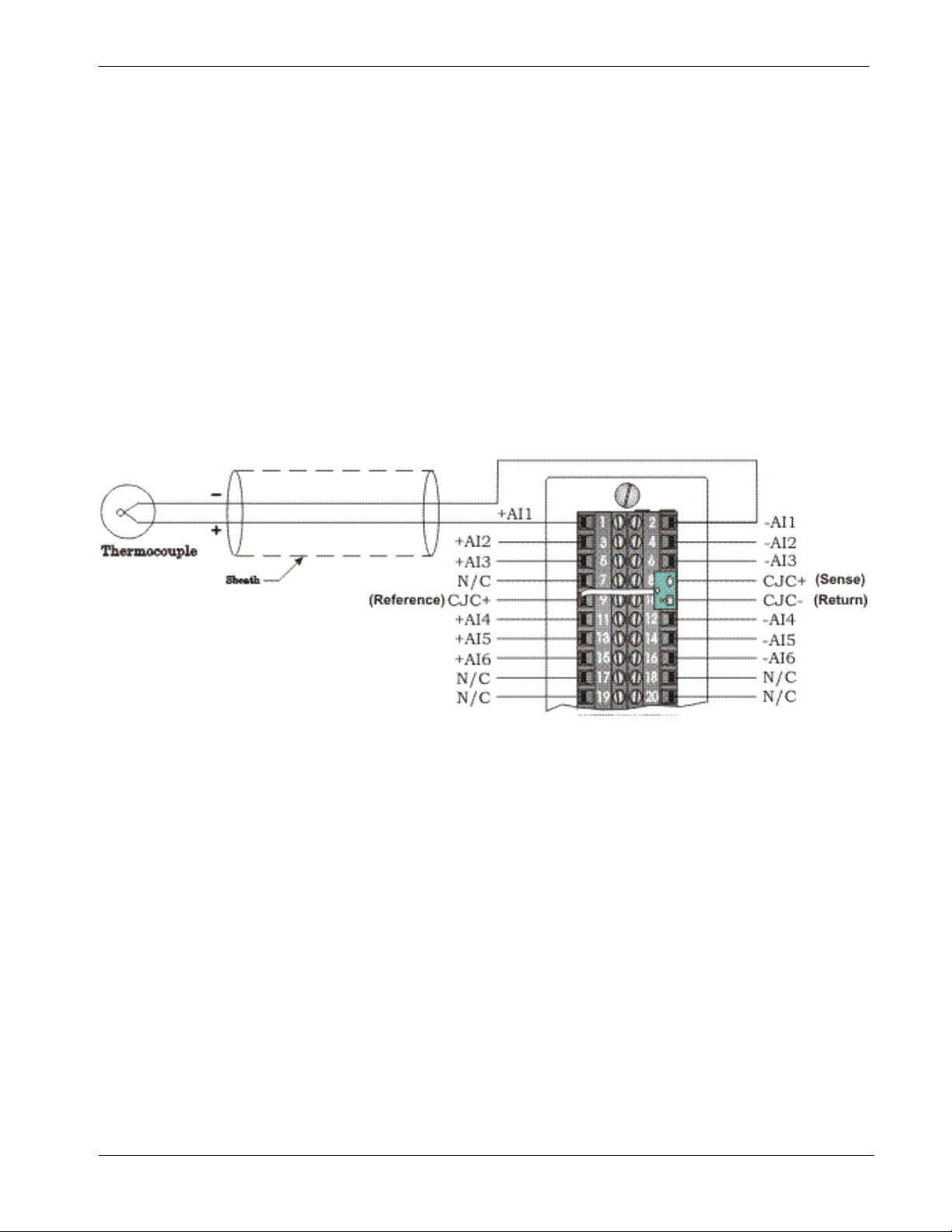
ControlWave I/O Expansion Rack Instruction Manual
Wiring the Module
Figure 3-34 shows field wiring for locally terminated isolated
thermocouple modules. Figure 3-35 shows field wiring for remotely
terminated isolated thermocouple modules.
The cold junction compensation (CJC) with a built-in RTD provides
thermocouple temperature compensation at the terminal block and is
electrically isolated. Pins 8, 9 and 10 of the local terminal block source
and sink the CJC’s RTD.
Figure 3-35 also provides diagrams showing the wiring for
thermocouples and the 3-wire RTDs to a locally terminated
thermocouple module. Wiring assignments (that is, +AI#, -AI#, +CJC
(Sense), -CJC (Return) & +CJC (Reference) are similar to those
assigned to the remote DIN-rail mountable terminal blocks. A small
CJC PCB is factory-installed to the terminal block.
Figure 3-33. Isolated Thermocouple Module Wiring Diagram
Revised Aug-2015 I/O Modules 3-41
Page 90

ControlWave I/O Expansion Rack Instruction Manual
Figure 3-34. Local Isolated Thermocouple Module Terminal Block Assembly Assignments
3-42 I/O Modules Revised Aug-2015
Page 91

ControlWave I/O Expansion Rack Instruction Manual
Figure 3-35. Remote DIN-Rail Mountable Terminal Block Assembly Assignments for Isolated
Thermocouple Module Operation
Revised Aug-2015 I/O Modules 3-43
Page 92

ControlWave I/O Expansion Rack Instruction Manual
Ranges &
Errors
Table 3-20 provides the accuracy, resolution and temperature range for
the various thermocouples and 10mV LLAI inputs. Table 3-21 lists the
RTD error with the CJC.
Table 3-20. Thermocouple Module Input Accuracy and Resolution
Input Type Accuracy/Range Resolution
B – Thermocouple
R – Thermocouple
S – Thermocouple
C – Thermocouple
N – Thermocouple
J – Thermocouple
E – Thermocouple
K – Thermocouple
T – Thermocouple
10mV 10mV 1.2V 0.25% 0.05%
Note: The CJC RTD adds an additional error (see Table 3-21)
100C to 200C
200C to 390C
390C to 840C
840C to 1820C
–50C to +50C
+50C to 1720C
– 50C to +50C
+50C to 1760C
0C to 2315C 0.16C 0.75C 1.5C
– 270C to – 260C
– 260C to – 250C
– 250C to – 230C
– 230C to – 150C
– 150C to 1300C
– 210C to 191C
190C to 1200C
– 270C to – 260C
– 260C to – 225C
– 225C to – 200C
– 200C to 1000C
– 270C to – 261C
– 260C to – 246C
– 245C to – 180C
– 179C to – 145C
– 145C to 1372C
– 270C to – 261C
– 260C to – 251C
– 250C to – 181C
– 180C to – 136C
– 135C to – 400C
2.00C
1.00C
0.50C
0.20C
0.40C
0.17C
0.37C
0.18C
1.50C
0.75C
0.50C
0.25C
0.09C
0.08C
0.11C
1.00C
0.25C
0.08C
0.09C
2.00C
0.56C
0.25C
0.08C
0.14C
1.50C
0.38C
0.18C
0.08C
0.06C
25C –20C to +70C
8C
4C
2C
1C
2C
1C
2C
1C
8C
4C
2C
1C
0.500C
0.750C
0.500C
3C
1C
0.750C
0.500C
5C
2C
1C
0.750C
0.500C
4C
2C
1C
0.750C
0.500C
16C
8C
4C
2C
4C
2C
4C
2C
10C
8C
4C
2C
1C
1.5C
1C
6C
2C
1.5C
1C
10C
4C
2C
1.5C
1C
8C
4C
2C
1.5C
1C
Table 3-21. Thermocouple Module RTD Error with CJC at 25C
Thermocouple
Type
B
R
S
3-44 I/O Modules Revised Aug-2015
Process Temperature
Range
100C to 1820C 0.30C
– 50C to +50C
+50C to 1720C
– 50C to +50C
+50C to 1760C
RTD Error with CJC
@ 25C
0.49C
0.30C
0.45C
0.30C
Page 93

ControlWave I/O Expansion Rack Instruction Manual
Software Configuration
Thermocouple
Type
C
N
J
E
K
T
Note: Use straight-line approximation to calculate approximate error between
end points.
Process Temperature
Range
0C to 2315C 0.30C
– 270C to – 261C
– 260C to – 251C
– 250C to – 231C
– 230C to – 189C
– 188C to – 70C
– 70C to + 25C
+25C to 1300C
– 210C to – 111C
– 110C to +25C
+25C to 1200C
– 270C to – 261C
– 260C to – 245C
– 244C to – 200C
– 200C to – 87C
– 86C to +25C
+25C to 100C
– 270C to – 261C
– 260C to – 247C
– 246C to – 222C
– 220C to – 160C
– 159C to +25C
+25C to 1372C
– 270C to – 261C
– 260C to – 243C
– 242C to – 196C
– 195C to – 61C
– 60C to +25C
+25C to 400C
RTD Error with CJC
@ 25C
20.50C
5.00C
2.70C
1.40C
0.70C
0.35C
0.30C
0.80C
0.40C
0.30C
10C
3C
1.50C
0.75C
0.39C
0.30C
15.00C
4.50C
2.20C
1.10C
0.55C
0.30C
10.30C
3.00C
1.50C
0.75C
0.375C
0.30C
To use data from any ControlWave thermocouple module in the rack
you must use ControlWave Designer’s I/O Configurator to modify the
ControlWave project in the host controller to add an ER_TC12 board
and then configure it. See the ControlWave Designer Programmer's
Handbook (D5125) for more information. That same manual includes
an I/O Mapping section that describes, for advanced users, the I/O map
for this module.
Revised Aug-2015 I/O Modules 3-45
Page 94

This page is intentionally left blank
Page 95

ControlWave I/O Expansion Rack Instruction Manual
Chapter 4 – Operation
This chapter provides general operational details for using the
ControlWave I/O expansion rack.
In This Chapter
4.1 Powering Up/Powering Down the ControlWave I/O Expansion Rack4-1
4.2 Communicating with the ControlWave I/O Expansion Rack ........... 4-1
4.2.1 Default Comm Port Settings ................................................. 4-1
4.2.2 Changing Port Settings ........................................................ 4-2
4.1 Powering Up/Powering Down the ControlWave I/O Expansion Rack
Open the bezel door on the PSSM and position the power switch (or
switches if you have dual supplies) to the OFF (down) position to turn
the ControlWave I/O rack OFF or to the ON (up) position to turn it ON.
ON position (up) to turn ON the power supply
OFF position (down) to turn OFF the power supply
Figure 4-1. Power Switches on PSSM Setting the Operating Mode (Run/Remote/Local Switch)
4.2 Communicating with the ControlWave I/O Expansion Rack
You communicate to the ControlWave I/O rack by connecting a cable
between a port on your PC workstation and one of the ControlWave I/O
rack ports. See Section 2.4 for more information on communications.
The port at the PC workstation must match the configuration of the
ControlWave I/O rack port.
4.2.1 Default Comm Port Settings
As delivered from the factory, ControlWave communication ports have
default settings. Table 4-1 details these defaults.
Table 4-1. Default Comm Port Settings (by PCB)
Port PCB Default Configuration
COM1 CPU Ships from factory at RS-232; 115.2 Kbps using BSAP. Once the default
switch is OFF, a factory default of IP Point-to-Point protocol (PPP) at
115,200 applies with an IP address of 1.1.1.1 and a mask of
255.255.255.255.
COM2 CPU RS-232; 9600 baud, 8 bits, no parity, 1 stop bit, RTU message type
Revised Aug-2015 Operation 4-1
Page 96

ControlWave I/O Expansion Rack Instruction Manual
Port PCB Default Configuration
Modbus Slave protocol
COM3 SCB RS-485; 9600 baud, 8 bits, no parity, 1 stop bit, BSAP or ControlWave
Designer protocol
COM4 SCB RS-232; 9600 baud, 8 bits, no parity, 1 stop bit, BSAP or ControlWave
Designer protocol
Note: You can re-enable the factory comm settings at any time by
setting switch 3 on the CPU module’s SW1 to “OFF.”
Ethernet
The ControlWave I/O expansion rack can include one or three Ethernet
ports. You can connect directly or through a network to a PC equipped
with an Ethernet port.
The factory pre-configures the initial IP addresses and masks to:
ETH1 IP Address: 10.0.1.1 IP Mask: 255.255.255.0
ETH2 IP Address: 10.0.2.1 IP Mask: 255.255.255.0
ETH3 IP Address: 10.0.3.1 IP Mask: 255.255.255.0
Because each unit ships from the factory with these addresses initially
pre-programmed, you should only use these addresses for “bench”
testing and configuration. You must change these addresses before
putting the I/O rack on an actual network, since an address conflict
would exist as soon as you place the second ControlWave unit online.
4.2.2 Changing Port Settings
You change port settings (baud rate, port type, IP address, and so on)
using the Flash Configuration utility.
You must establish communications with the ControlWave using
NetView, LocalView, or TechView before you can run the Flash
Configuration utility.
Note: For detailed information on using the Flash Configuration utility,
see Chapter 5 of the OpenBSI Utilities Manual (D5081).
Caution
4-2 Operation Revised Aug-2015
When you change the baud rate for a port, the baud rate changes as
soon as you write the flash file changes to the RTU, and do not require
a reset. For this reason, you should not change baud rate for the active
port on which you are communicating, or communications will
immediately stop due to the baud rate mismatch between the PC port
and the controller port. If this happens accidentally, you can use CPU
switch settings as discussed in the notes in Section 4.2.1 to restore
defaults and re-establish communications.
Page 97

ControlWave I/O Expansion Rack Instruction Manual
Chapter 5 – Service and Troubleshooting
This chapter provides general diagnostic and test information for the
ControlWave I/O expansion rack.
In This Chapter
5.1 Upgrading Firmware ........................................................................ 5-2
5.2 Removing or Replacing Components .............................................. 5-5
5.2.1 Accessing Modules for Testing ............................................ 5-5
5.2.2 Removing/Replacing the Bezel ............................................ 5-5
5.2.3 Removing/Replacing the CPU Module................................. 5-6
5.2.4 Removing/Replacing the PSSM ........................................... 5-6
5.2.5 Removing/Replacing an I/O Module (Hot Swapping) .......... 5-7
5.2.6 Removing/Replacing the Backup Battery .......................... 5-12
5.3 General Troubleshooting Procedures ........................................... 5-13
5.3.1 Common Communication Configuration Problems ............ 5-13
5.3.2 Checking LEDs ................................................................... 5-14
5.3.3 Checking Wiring/Signals .................................................... 5-22
5.3.4 Port 80 Display Codes ........................................................ 5-22
5.3.5 Reset Switch ...................................................................... 5-26
5.4 WINDIAG Diagnostic Utility ........................................................... 5-26
5.4.1 Available Diagnostics ......................................................... 5-28
5.5 Core Updump ................................................................................ 5-32
Equipment
You need the following equipment to perform the procedures described
in this chapter:
To run diagnostics software:
PC with WINDIAG software, and either OpenBSI LocalView,
NetView, or TechView for communications.
Null modem interface cable
Loop-back plug for RS-232 port (see Figure 5-22)
Loop-back plug for RS-485 port (see Figure 5-23)
Loop-back plug, 8-pin RJ-45 male (for twisted pair Ethernet) (see
Figure 5-25)
To perform firmware upgrades:
Null modem interface cable
PC with the following software:
o OpenBSI System Firmware Downloader and either NetView,
LocalView, or TechView for communications.
o HyperTerminal (included in Windows® XP)
Note: When you service a ControlWave on site, we recommend that
you close down (or place under manual control) any associated
processes. This precaution prevents any processes from
accidentally running out of control when you conduct tests.
Revised Aug-2015 Service & Troubleshooting 5-1
Page 98

ControlWave I/O Expansion Rack Instruction Manual
Warning
Harmful electrical potentials may still exist at the field wiring terminals
even though the ControlWave power source may be turned off or
disconnected. Do not attempt to unplug termination connectors or
perform any wiring operations until you verify that all associated power
supply sources are turned off and/or disconnected.
Always turn off any external supply sources for externally powered I.O
circuits before you change any modules.
5.1 Upgrading Firmware
The ControlWave I/O expansion rack CPU ships from the factory with
system firmware already installed. If you need to upgrade the system
firmware (stored in Flash memory) to acquire new functionality or
restore firmware, you can use one of several methods.
System
Firmware
Downloader
Use this tool to download system firmware to an unattended remote I/O
rack. To use this utility, you must set CPU module switch SW3-2 OFF
(the factory default position).
Note: For further information and detailed use instructions, refer to
Appendix J of the OpenBSI Utilities Manual (D5081).
LocalView
HyperTerminal
One of the standard OpenBSI utilities, LocalView requires OpenBSI
version 5.1 (or newer). If you have an older version of OpenBSI, use
HyperTerminal.
Note: For further information and detailed use instructions, refer to the
Flash Mode section of Chapter 5 of the OpenBSI Utilities
Manual (D5081).
HyperTerminal is a communications utility program included with
Microsoft® Windows®.XP
Notes:
If you are using a version of OpenBSI older than 5.1, or do not have
OpenBSI software, you can only perform a firmware upgrade using
HyperTerminal.
While HyperTerminal is included in Microsoft® Window® XP,
some newer versions of Window® do not include it.
HyperTerminal requires *.BIN files; newer ControlWave firmware
upgrade files use *.CAB files. In cases such as those, you should use
the Remote System Firmware Downloader.
1. Connect a null modem cable between COM1 of the
ControlWave and any RS-232 port on the associated PC.
2. Click Start > Programs > Accessories > Communications >
HyperTerminal
5-2 Service & Troubleshooting Revised Aug-2015
Page 99

ControlWave I/O Expansion Rack Instruction Manual
3. If using HyperTerminal for the first time, set the communication
properties (for the PC port) via the Properties Menu as follows:
Bits per second: = 115200, Data bits: = 8, Parity: = None, Stop
bits: = 1, and Flow control: = None and then click OK.
4. Set CPU switch SW3-3 to ON (Force Recovery Mode).
5. Apply power; to the ControlWave. The resident BIOS initializes
and tests the hardware, this process is referred to as POST
(Power On Self Test). Unless there is a problem, you should see
the code “86” on the Port 80 display. If you see a different status
code, see Section 5.3.4.
6. From the HyperTerminal Mode menu (Figure 5-1), press the F
key to enter FLASH download. A message warns that the
FLASH is about to be erased; press the Y key at the prompt. The
screen displays dots as the system erases the flash memory; this
could take a few minutes.
Figure 5-1. HyperTerminal Mode Menu
7. When the FLASH is ready for download, HyperTerminal
repeatedly displays the letter C on the screen. In the
HyperTerminal menu bar click Transfer > Send File (see
Figure 5-2).
Revised Aug-2015 Service & Troubleshooting 5-3
Page 100

ControlWave I/O Expansion Rack Instruction Manual
Figure 5-2. HyperTerminal (Ready to Download)
8. In the Send File dialog box (see Figure 5-3), select 1KXmodem
for the protocol, enter the filename of the appropriate .bin file in
the format “CWPxxxxx.bin” (where xxxxx varies from release to
release) and click Send to start the flash upgrade (see Figure 5-
4). When you see the HyperTerminal Mode Menu again, it
means the download has completed.
9. Exit HyperTerminal and power down the ControlWave. If
desired, you can disconnect the null modem cable between the
ControlWave and the PC.
10. Set CPU switch SW3-3 to OFF (Recovery Mode Disabled).
11. Restore power to the ControlWave I/O expansion rack.
Figure 5-3. Send File dialog box
5-4 Service & Troubleshooting Revised Aug-2015
 Loading...