

Page 1

CONTROL VALVE
HANDBOOK
Fifth Edition
Page 2

Emerson Automation Solutions
Flow Controls
Marshalltown, Iowa 50158 USA
Sorocaba, 18087 Brazil
Cernay, 68700 France
Dubai, United Arab Emirates
Singapore 128461 Singapore
Neither Emerson, Emerson Automation Solutions, nor any of their afliated entities assumes
responsibility for the selection, use or maintenance of any product. Responsibility for proper
selection, use, and maintenance of any product remains solely with the purchaser and end user.
The contents of this publication are presented for informational purposes only, and while every
effort has been made to ensure their accuracy, they are not to be construed as warranties or
guarantees, express or implied, regarding the products or services described herein or their use
or applicability. All sales are governed by our terms and conditions, which are available upon
request. We reserve the right to modify or improve the designs or specications of such products
at any time without notice.
Fisher is a mark owned by one of the companies in the Emerson Automation Solutions business
unit of Emerson Electric Co. Emerson and the Emerson logo are trademarks and service marks
of Emerson Electric Co. All other marks are the property of their respective owners.
© 2005, 2019 Fisher Controls International LLC. All rights reserved.
D101881X012/ Sept19
Page 3

Preface
Control valves are an increasingly vital component of modern manufacturing around
the world. Properly selected and maintained control valves increase efciency,
safety, protability, and ecology.
The Control Valve Handbook has been a primary reference since its rst printing in
1965. This fth edition presents vital information on control valve performance and
the latest technologies.
Chapter 1 offers an introduction to control valves, including denitions for common
control valve and instrumentation terminology.
Chapter 2 develops the vital topic of control valve performance.
Chapter 3 covers valve and actuator types.
Chapter 4 describes digital valve controllers, analog positioners, boosters, and other
control valve accessories.
Chapter 5 is a comprehensive guide to selecting the best control valve for an
application.
Chapter 6 addresses the selection and use of special control valves.
Chapter 7 explains desuperheaters, steam conditioning valves, and turbine bypass
systems.
Chapter 8 details typical control valve installation and maintenance procedures.
Chapter 9 contains information on control valve standards and approval agencies
across the world.
Chapter 10 identies isolation valves and actuators.
Chapter 11 covers discrete automation.
Chapter 12 discusses various process safety instrumented systems.
Chapter 13 provides useful tables of engineering reference data.
Chapter 14 includes piping reference data.
Chapter 15 is a handy resource for common conversions.
The Control Valve Handbook is both a textbook and a reference on the strongest link
in the control loop: the control valve and its accessories. This book includes extensive
and proven knowledge from leading experts in the process control eld, including
contributions from the ISA.
Page 4

Table of Contents
Page 5

Control Valve Handbook | Table of Contents
Chapter 1: Introduction to Control Valves ............................................. 14
1.1 What is a Control Valve? .............................................................................. 15
1.2 Sliding-Stem Control Valve Terminology .....................................................15
1.3 Rotary Control Valve Terminology ...............................................................21
1.4 Control Valve Functions and Characteristics Terminology ............................23
1.5 Process Control Terminology .......................................................................25
Chapter 2: Control Valve Performance .................................................. 32
2.1 Process Variability ....................................................................................... 33
2.1.1 Deadband ................................................................................................................ 35
2.1.1.1 Causes of Deadband .........................................................................................................35
2.1.1.2 Effects of Deadband .........................................................................................................36
2.1.1.3 Performance Tests ............................................................................................................36
2.1.1.4 Friction ............................................................................................................................36
2.1.2 Actuator and Positioner Design ................................................................................ 37
2.1.3 Valve Response Time ................................................................................................ 38
2.1.3.1 Dead Time .......................................................................................................................38
2.1.3.2 Dynamic Time ..................................................................................................................38
2.1.3.3 Solutions ..........................................................................................................................39
2.1.3.4 Supply Pressure ................................................................................................................40
2.1.3.5 Minimizing Dead Time .....................................................................................................40
2.1.3.6 Valve Response Time ........................................................................................................41
2.1.4 Valve Type and Characterization ............................................................................... 41
2.1.4.1 Installed Gain ...................................................................................................................43
2.1.4.2 Loop Gain ........................................................................................................................43
2.1.4.3 Process Optimization .......................................................................................................44
2.1.5 Valve Sizing .............................................................................................................. 45
2.2 Economic Results ........................................................................................46
2.3 Summary .................................................................................................... 48
Chapter 3: Valve and Actuator Types ..................................................... 50
3.1 Control Valve Styles .................................................................................... 51
3.1.1 Globe Valves ............................................................................................................ 51
3.1.1.1 Single-Port Valve Bodies ...................................................................................................51
3.1.1.2 Post- and Port-Guided Valve Bodies ...................................................................................52
3.1.1.3 Cage-Style Valve Bodies ....................................................................................................52
3.1.1.4 Double-Ported Valve Bodies ..............................................................................................53
3.1.1.5 Three-Way Valve Bodies....................................................................................................53
3.1.2 Sanitary Valves ........................................................................................................ 54
3.1.3 Rotary Valves ........................................................................................................... 54
3.1.3.1 Buttery Valve Bodies .......................................................................................................54
3.1.3.2 Segmented Ball Valve Bodies ............................................................................................55
5
Page 6

Control Valve Handbook | Table of Contents
3.1.3.3 High-Performance Buttery Valve Bodies ..........................................................................55
3.1.3.4 Eccentric Plug Valve Bodies ...............................................................................................56
3.1.3.5 Full-Port Ball Valve Bodies .................................................................................................57
3.1.3.6 Multi-Port Flow Selector ...................................................................................................57
3.2 Control Valve End Connections ................................................................... 57
3.2.1 Screwed Pipe Threads .............................................................................................. 57
3.2.2 Bolted Gasketed Flanges ........................................................................................... 58
3.2.3 Welded End Connections .......................................................................................... 58
3.2.4 Other Valve End Connections ................................................................................... 59
3.3 Valve Body Bonnets .....................................................................................59
3.3.1 Extension Bonnets.................................................................................................... 60
3.3.2 Bellows Seal Bonnets ................................................................................................ 61
3.4 Control Valve Packing..................................................................................61
3.4.1 PTFE V-Ring .............................................................................................................. 62
3.4.2 Laminated and Filament Graphite ............................................................................ 62
3.4.3 U.S. Regulatory Requirements for Fugitive Emissions ................................................ 62
3.4.4 Global Standards for Fugitive Emissions .................................................................... 63
3.4.5 Single PTFE V-Ring Packing ....................................................................................... 65
3.4.6 ENVIRO-SEAL PTFE Packing....................................................................................... 65
3.4.7 ENVIRO-SEAL Duplex Packing ................................................................................... 67
3.4.8 ISO-Seal PTFE Packing .............................................................................................. 67
3.4.9 ENVIRO-SEAL Graphite ULF ....................................................................................... 67
3.4.10 HIGH-SEAL Graphite ULF ........................................................................................ 67
3.4.11 ISO-Seal Graphite Packing ...................................................................................... 67
3.4.12 ENVIRO-SEAL Graphite for Rotary Valves ................................................................. 67
3.4.13 Graphite Ribbon for Rotary Valves .......................................................................... 67
3.4.14 Sliding-Stem Environmental Packing Selection........................................................ 67
3.4.15 Rotary Environmental Packing Selection ................................................................. 69
3.5 Characterization of Cage-Guided Valve Bodies ............................................ 69
3.6 Valve Plug Guiding ......................................................................................70
3.7 Restricted-Capacity Control Valve Trim .......................................................70
3.8 Actuators .................................................................................................... 71
3.8.1 Diaphragm Actuators .............................................................................................. 71
3.8.2 Piston Actuators ...................................................................................................... 72
3.8.4 Rack-and-Pinion Actuators ....................................................................................... 73
3.8.5 Electric Actuators ..................................................................................................... 73
Chapter 4: Control Valve Accessories .................................................... 74
4.1 Environmental & Application Considerations ............................................... 75
4.2 Positioners ..................................................................................................75
4.2.1 Pneumatic Positioners .............................................................................................. 75
6
Page 7

Control Valve Handbook | Table of Contents
4.2.2 Analog I/P Positioners .............................................................................................. 76
4.2.3 Digital Valve Controllers ........................................................................................... 77
4.2.3.1 Diagnostics ......................................................................................................................77
4.2.3.2 Two-Way Digital Communication .....................................................................................78
4.3 I/P Transducers ............................................................................................ 78
4.4 Volume Boosters ......................................................................................... 78
4.5 Safety Instrumented Systems (SIS) .............................................................. 80
4.5.1 Partial Stroke Testing ............................................................................................... 80
4.6 Controllers ..................................................................................................81
4.7 Position Transmitters ..................................................................................83
4.8 Limit Switches .............................................................................................83
4.9 Solenoid Valves ........................................................................................... 83
4.10 Trip Systems .............................................................................................. 84
4.11 Handwheels ..............................................................................................84
Chapter 5: Control Valve Sizing ............................................................. 86
5.1 Control Valve Dimensions ...........................................................................88
5.1.1 Face-to-Face Dimensions for Flanged, Globe-Style Valves .......................................... 88
5.1.2 Face-to-Face Dimensions for Butt Weld-End, Globe-Style Valves ................................ 90
5.1.3 Face-to-Face Dimensions for Socket Weld-End, Globe-Style Valves ............................ 91
5.1.4 Face-to-Face Dimensions for Screwed-End, Globe-Style Valves .................................. 92
5.1.5 Face-to-Centerline Dimensions for Raised-Face, Globe-Style Angle Valves ..................... 92
5.1.6 Face-to-Face Dimensions for Separable Flange, Globe-Style Valves ............................ 93
5.1.7 Face-to-Face Dimensions for Flanged and Flangeless Rotary Valves ........................... 93
5.1.8 Face-to-Face Dimensions for Single Flange and Flangeless Buttery Valves ................... 94
5.1.9 Face-to-Face Dimensions for High-Pressure, Offset Buttery Valves ........................... 94
5.2 Control Valve Seat Leakage Classications ................................................... 95
5.3 Class VI Maximum Seat Leakage Allowable ..................................................96
5.4 Control Valve Flow Characteristics...............................................................96
5.4.1 Flow Characteristics ................................................................................................. 96
5.4.2 Selection of Flow Characteristics .............................................................................. 97
5.5 Valve Sizing .................................................................................................97
5.7 Equation Constants ....................................................................................99
5.8 Sizing Valves for Liquids .............................................................................100
5.8.1 Determining Piping Geometry Factor and Liquid Pressure-Recovery Factor .................. 100
5.8.2 Determining the Pressure Drop to Use for Sizing ..................................................... 101
5.8.3 Calculating the Required Flow Coefcient ............................................................... 101
5.8.4 Liquid Sizing Sample Problem ................................................................................. 102
5.9 Sizing Valves for Compressible Fluids.........................................................104
5.9.1 Determining Piping Geometry Factor and Pressure Drop Ratio Factor at Choked Flow ................. 105
7
Page 8

Control Valve Handbook | Table of Contents
5.9.2 Determining Pressure Drop Ratio to Use for Sizing and Expansion Factor ................... 105
5.9.3 Calculating Flow Coefcient ................................................................................... 105
5.9.4 Compressible Fluid Sizing Sample Problem No. 1 .................................................... 106
5.9.5 Compressible Fluid Sizing Sample Problem No. 2 .................................................... 107
5.10 Representative Sizing Coefcients ...........................................................109
5.10.1 Representative Sizing Coefcients for Single-Ported, Globe-Style Valves................. 109
5.10.2 Representative Sizing Coefcients for Rotary Valves ............................................. 110
5.11 Actuator Sizing........................................................................................111
5.11.1 Globe Valves ........................................................................................................ 111
5.11.1.1 Unbalance Force ..........................................................................................................111
5.11.1.2 Force to Provide Seat Load ............................................................................................112
5.11.1.3 Packing Friction ............................................................................................................112
5.11.1.4 Additional Forces ..........................................................................................................112
5.11.2 Actuator Force Calculations ................................................................................. 114
5.12 Actuator Sizing for Rotary Valves ............................................................. 114
5.12.1 Torque Equations ................................................................................................. 114
5.12.2 Breakout Torque .................................................................................................. 114
5.12.3 Dynamic Torque .................................................................................................. 114
5.13 Typical Rotary Valve Torque Factors .........................................................115
5.13.1 Torque Factors for V-Notch Ball Valve with Composition Seal ................................ 115
5.13.2 Torque Factors for Buttery Valve with Composition Seal ...................................... 115
5.13.2.1 Maximum Rotation ......................................................................................................115
5.14 Cavitation and Flashing ...........................................................................116
5.14.1 Choked Flow Causes Flashing and Cavitation ........................................................ 116
5.14.2 Valve Selection for Flashing Service ....................................................................... 117
5.14.3 Valve Selection for Cavitation Service ................................................................... 118
5.15 Noise Prediction ...................................................................................... 118
5.15.1 Aerodynamic ....................................................................................................... 118
5.15.2 Hydrodynamic ..................................................................................................... 120
5.16 Noise Control ..........................................................................................120
5.17 Noise Summary ......................................................................................123
5.18 Packing Selection ....................................................................................124
5.18.1 Packing Selection Guidelines for Sliding-Stem Valves............................................. 125
5.18.2 Packing Selection Guidelines for Rotary Valves ...................................................... 126
5.19 Valve Body Materials ...............................................................................127
5.19.1 Designations for Common Valve Body Materials ................................................... 129
5.20 Pressure-Temperature Ratings ................................................................. 130
5.20.1 Standard Class ASTM A216 Grade WCC Cast Valves ................................................ 130
5.20.2 Standard Class ASTM A217 Grade WC9 Cast Valves .............................................. 131
5.20.3 Standard Class ASTM A351 Grade CF3 Cast Valves ................................................ 132
5.20.4 Standard Class ASTM A351 Grades CF8M and CG8M Valves .................................. 133
8
Page 9

Control Valve Handbook | Table of Contents
5.21 Non-Metallic Material Abbreviations .......................................................135
5.22 Non-Destructive Test Procedures ............................................................ 135
5.22.1 Magnetic Particle (Surface) Examination .............................................................. 135
5.22.2 Liquid Penetrant (Surface) Examination ............................................................... 136
5.22.3 Radiographic (Volumetric) Examination ............................................................... 136
5.22.4 Ultrasonic (Volumetric) Examination .................................................................... 136
Chapte 6: Special Control Valves ......................................................... 138
6.1 High-Capacity Control Valves ....................................................................139
6.2 Low-Flow Control Valves ...........................................................................140
6.3 High-Temperature Control Valves .............................................................140
6.4 Cryogenic Service Valves ...........................................................................141
6.5 Valves Subjected to Cavitation and Fluids with Particulate .........................141
6.6 Customized Characteristics, Noise-Abatement, and Cavitation-Mitigation
Trims ..............................................................................................................142
6.7 Control Valves for Nuclear Service in the U.S. ............................................142
6.8 Valves Subjected to Sulde Stress Cracking ............................................... 143
6.8.1 Pre-2003 Revisions of NACE MR0175 ...................................................................... 143
6.8.2 NACE MR0175/ISO 15156 ........................................................................................ 144
6.8.3 NACE MR0103 .......................................................................................................... 145
Chapter 7: Steam Conditioning ........................................................... 146
7.1 Understanding Desuperheating ................................................................147
7.1.1 Technical Aspects of Desuperheating ...................................................................... 147
7.2 Typical Desuperheater Designs ..................................................................150
7.2.1 Fixed-Geometry Nozzle Design ............................................................................... 150
7.2.2 Variable-Geometry Nozzle Design .......................................................................... 151
7.2.3 Self-Contained Design ............................................................................................ 151
7.2.5 Geometry-Assisted Wafer Design ........................................................................... 152
7.3 Understanding Steam Conditioning Valves................................................153
7.4 Steam Conditioning Valves ........................................................................153
7.4.1 Steam Attemperator .............................................................................................. 155
7.4.2 Steam Sparger ....................................................................................................... 155
7.6 Turbine Bypass System Components .........................................................156
7.6.1 Turbine Bypass Valves............................................................................................. 156
7.6.2 Turbine Bypass Water Control Valves ...................................................................... 156
7.6.3 Actuation............................................................................................................... 157
Chapter 8: Installation and Maintenance ............................................. 158
8.1 Proper Storage and Protection .................................................................. 159
9
Page 10

Control Valve Handbook | Table of Contents
8.2 Proper Installation Techniques ..................................................................159
8.2.1 Read the Instruction Manual .................................................................................. 159
8.2.2 Be Sure the Pipeline Is Clean ................................................................................... 159
8.2.4 Use Good Piping Practices ...................................................................................... 160
8.2.5 Flushing/Hydro/Start-Up Trim ................................................................................ 161
8.3 Control Valve Maintenance........................................................................161
8.3.1 Reactive Maintenance ............................................................................................ 162
8.3.2 Preventive Maintenance ......................................................................................... 162
8.3.3 Predictive Maintenance .......................................................................................... 162
8.3.4 Using Control Valve Diagnostics ............................................................................. 162
8.3.4.1 Instrument Air Leakage ..................................................................................................163
8.3.4.2 Supply Pressure ..............................................................................................................163
8.3.4.3 Travel Deviation and Relay Adjustment ...........................................................................163
8.3.4.4 Instrument Air Quality ....................................................................................................164
8.3.4.5 In-Service Friction and Friction Trending ..........................................................................164
8.3.4.6 Other Examples ..............................................................................................................164
8.3.5 Continued Diagnostics Development ...................................................................... 164
8.4 Service and Repair Parts ............................................................................165
8.4.1 Recommended Spare Parts .................................................................................... 165
8.4.2 Using Original Equipment Manufacturers (OEM) Parts ............................................ 165
8.4.3 Consider Upgrades for the Valve Trim ..................................................................... 165
8.5 Actuator Maintenance ............................................................................... 165
8.5.1 Spring-and-Diaphragm Actuators ......................................................................... 165
8.5.2 Piston Actuators .................................................................................................... 166
8.5.3 Stem Packing ......................................................................................................... 166
8.5.4 Seat Rings .............................................................................................................. 166
8.5.4.1 Replacing Seat Rings ......................................................................................................166
8.5.4.2 Connections: Plug-to-Stem, Ball-to-Shaft, and Disk-to-Shaft...........................................167
8.5.5 Bench Set ............................................................................................................... 167
8.5.6 Valve Travel ............................................................................................................ 167
Chapter 9: Standards and Approvals ................................................... 168
9.1 Control Valve Standards ............................................................................169
9.1.1 American Petroleum Institute (API) ......................................................................... 169
9.1.2 American Society of Mechanical Engineers (ASME) ................................................. 169
9.1.3 European Committee for Standardization (CEN) ..................................................... 169
9.1.3.1 European Industrial Valve Standards ...............................................................................169
9.1.3.2 European Material Standards .........................................................................................170
9.1.3.3 European Flange Standards ............................................................................................170
9.1.4 Fluid Controls Institute (FCI) ................................................................................... 170
9.1.5 Instrument Society of America (ISA) ....................................................................... 170
9.1.6 International Electrotechnical Commission (IEC) ..................................................... 171
10
Page 11

Control Valve Handbook | Table of Contents
9.1.7 Manufacturers Standardization Society (MSS) ........................................................ 171
9.1.8 NACE International ................................................................................................. 171
9.2 Product Approvals for Hazardous (Classied) Locations .............................172
9.2.1 Hazardous Location Approvals and Denitions ....................................................... 172
9.3 Classication Systems ...............................................................................172
9.3.1 Class/Division System ............................................................................................. 172
9.3.2 Zone System .......................................................................................................... 173
9.3.3 Equipment Groups ................................................................................................. 174
9.3.4 Equipment Subgroups ............................................................................................ 174
9.3.4.1 Group II (Commonly referred to as the “Gas Group”) .......................................................174
9.3.4.2 Group III (Commonly referred to as the “Dust Group”) ....................................................174
9.3.5 Type of Protection .................................................................................................. 175
9.3.5.1 Electrical Equipment .......................................................................................................175
9.3.5.2 Non-Electrical Equipment ...............................................................................................176
9.3.6 Level of Protection .................................................................................................. 177
9.3.7 Equipment Protection Level (EPL) ............................................................................ 177
9.4 Temperature Code ....................................................................................178
9.5 Nomenclature ...........................................................................................179
9.5.1 Class/Division System ............................................................................................. 179
9.5.2 Zone System .......................................................................................................... 179
9.5.3 Wiring Practices ..................................................................................................... 179
9.5.4 European Union (EU) – ATEX Directive 2014/34/EU ................................................ 180
9.6 Protection Techniques and Methods .........................................................181
9.6.1 Explosion-Proof or Flame-Proof Technique .............................................................. 181
9.6.2 Intrinsically-Safe Technique .................................................................................... 181
9.6.3 Non-Incendive or Type n Technique......................................................................... 182
9.6.4 Increased Safety ..................................................................................................... 182
9.6.5 Dust Ignition-Proof or Enclosure Dust-Proof............................................................ 183
9.7 Enclosure Ratings ......................................................................................183
Chapter 10: Isolation Valves ............................................................... 186
10.1 Basic Valve Types .....................................................................................187
10.1.1 Gate Valves .......................................................................................................... 187
10.1.2 Globe Valves ........................................................................................................ 188
10.1.3 Check Valves ........................................................................................................ 191
10.1.4 Bypass Valves ....................................................................................................... 192
10.1.6 Pinch Valves ......................................................................................................... 193
10.1.7 Ball Valves ............................................................................................................ 194
10.1.8 Buttery Valves .................................................................................................... 194
10.1.9 Plug Valves ........................................................................................................... 195
11
Page 12

Control Valve Handbook | Table of Contents
Chapter 11: Solenoid Valves ................................................................ 210
11.1 Solenoid Valves ....................................................................................... 211
Chapter 12: Safety Instrumented Systems ........................................... 214
12.1 Safety and Layers of Protection ...............................................................215
12.2 Safety Instrumented Systems (SIS) .......................................................... 216
12.3 Safety Standards .....................................................................................217
12.4 Safety Integrity Level (SIL) .......................................................................217
12.5 Probability of Failure Upon Demand ........................................................ 218
Final Elements, Proof Testing, and Partial Stroke Testing Techniques ...............219
12.6
12.7 Partial Stroke Testing ..............................................................................219
12.8 Online Testing Methods for the Final Element..........................................220
12.9 Digital Valve Controller Use for Partial Stroke Testing ..............................220
12.10 High-Integrity Pressure Protection System (HIPPS) ...............................221
12.11 Functionality of the HIPPS ....................................................................221
12.12 Testing Requirements ...........................................................................221
Chapter 13: Engineering Data ............................................................. 224
13.1 Standard Specications for Pressure-Retaining Valve Materials ................225
13.2 Valve Material Properties for Pressure-Containing Components .............. 232
13.3 Physical Constants of Hydrocarbons ........................................................234
13.4 Specic Heat Ratio ..................................................................................237
13.5 Physical Constants of Various Fluids ........................................................238
Refrigerant 717 (Ammonia) Properties of Liquid and Saturated Vapor ..............240
13.6
13.7 Properties of Water .................................................................................247
13.8 Properties of Saturated Steam .................................................................248
13.9 Properties of Superheated Steam ............................................................ 257
Chapter 14: Pipe Data ......................................................................... 266
14.1 Pipe Engagement ....................................................................................267
14.2 Carbon and Alloy Steel - Stainless Steel ....................................................267
14.3 American Pipe Flange Dimensions ...........................................................275
14.3.1 Diameter of Bolt Circles ....................................................................................... 275
14.3.2 Number of Stud Bolts and Diameter ..................................................................... 276
14.3.3 Flange Diameter .................................................................................................. 277
14.3.4 Flange Thickness for Flange Fittings ...................................................................... 278
14.4 Cast Steel Flange Standards ..................................................................... 280
14.4.1 Cast Steel Flange Standard for PN 10 .................................................................... 280
14.4.2 Cast Steel Flange Standard for PN 16 .................................................................... 281
12
Page 13

Control Valve Handbook | Table of Contents
14.4.3 Cast Steel Flange Standard for PN 25 .................................................................... 282
14.4.4 Cast Steel Flange Standard for PN 40 .................................................................... 283
14.4.5 Cast Steel Flange Standard for PN 63 .................................................................... 284
14.4.6 Cast Steel Flange Standard for PN 100 .................................................................. 284
14.4.7 Cast Steel Flange Standard for PN 160 .................................................................. 285
14.4.8 Cast Steel Flange Standard for PN 250 .................................................................. 285
14.4.9 Cast Steel Flange Standard for PN 320 .................................................................. 286
14.4.10 Cast Steel Flange Standard for PN 400 ................................................................ 286
Chapter 15: Conversions and Equivalents ............................................ 288
15.1 Length Equivalents ..................................................................................289
15.2 Whole Inch to Millimeter Equivalents ......................................................289
15.3 Fractional Inch to Millimeter Equivalents .................................................290
15.4 Additional Fractional Inch to Millimeter Equivalents ................................291
15.5 Area Equivalents ......................................................................................293
15.6 Volume Equivalents .................................................................................293
15.7 Volume Rate Equivalents ......................................................................... 293
15.8 Mass Conversion–Pounds to Kilograms ................................................... 294
15.9 Pressure Equivalents ...............................................................................294
15.10 Pressure Conversion–Pounds Per Square Inch to Bar .............................295
15.11 Temperature Conversion Formulas ........................................................ 296
15.12 Temperature Conversions .....................................................................296
15.13 API and Baumé Gravity Tables and Weight Factors ................................ 299
15.14 Other Useful Conversions ...................................................................... 301
15.15 Metric Prexes and Sufxes ...................................................................302
Index .................................................................................................. 304
13
Page 14

Chapter 1
Introduction to Control Valves
Page 15

Control Valve Handbook | Chapter 1: Introduction to Control Valves
See Additional Resources »
1.1 What is a Control Valve?
Modern processing plants utilize a vast
network of control loops to produce an
end product for market. These control
loops are designed to keep a process
variable (i.e. pressure, ow, level,
temperature, etc.) within a required
operating range to ensure a quality end
product is produced. Each of these loops
receives and internally creates
disturbances that detrimentally affect
the process variable (PV). Interaction
from other loops in the network also
provide disturbances that inuence the
process variable. See Figure 1.1.
Manipulated
Variable
Control
Valve
Figure 1.1 Feedback Control Loop
Process
Controller
To reduce the effect of these load
disturbances, sensors and transmitters
collect information about the process
variable (PV) and its relationship to some
desired set point. A controller processes
this information and decides what must
be done to get the process variable back
to where it should be after a load
disturbance occurs. When all the
measuring, comparing, and calculating
are done, some type of nal control
element must implement the strategy
selected by the controller.
The most common nal control element
in the process control industries is the
control valve. The control valve
manipulates a owing uid, such as gas,
steam, water, or chemical compounds to
compensate for the load disturbance and
keep the regulated process variable as
close as possible to the desired set point.
Controlled
Variable
Sensor
Transmitter
The control valve is a critical part of the
control loop. Many people who talk
about control valves are really referring
to a control valve assembly. The control
valve assembly typically consists of the
valve body, the internal trim parts, an
actuator to provide the motive power to
operate the valve, and a variety of
additional valve accessories, which can
includes, transducers, supply pressure
regulators, manual operators, snubbers,
or limit switches.
There are two main types of control
valve designs, depending on the action
of the closure member: sliding-stem or
rotary. Sliding-stem valves, as seen in
Figure 1.2 and 1.3, use linear motion to
move a closure member into and out of
a seating surface. Rotary valves, as seen
in Figure 1.13 and 1.17, use rotational
motion to turn a closure member into
and out of a seating surface.
1.2 Sliding-Stem Control Valve Terminology
The following terminology applies to the
physical and operating characteristics of
standard sliding-stem control valves
with diaphragm or piston actuators.
Some of the terms, particularly those
pertaining to actuators, are also
appropriate for rotary control valves.
Many of the denitions presented are in
accordance with ANSI/ISA-75.05.01,
Control Valve Terminology, although
other popular terms are also included.
Additional explanation is provided for
some of the more complex terms.
Additional sections in this chapter follow
that dene specic terminology for
rotary control valves, general process
control, and control valve functions and
characteristics.
15
Page 16

Control Valve Handbook | Chapter 1: Introduction to Control Valves
Actuator Stem Force: The net force
from an actuator that is available for
actual positioning of the valve plug,
referred to as valve travel.
Angle Valve: A valve design in which the
inlet and outlet ports are perpendicular
to each other. See also Globe Valve.
Figure 1.2 Sliding-Stem Control Valve
1. Bonnet
2. Packing Box
3. Cage or Seat
Ring Retainer
4. Valve Stem
1
2
3
6
5. Valve Plug
6. Valve Body
7. Seat Ring
8. Port
4
5
Figure 1.4 Angle Valve
Bellows Seal Bonnet: A bonnet that
uses a bellows for sealing against
leakage around the closure member
stem. See Figure 1.5.
Bonnet: The portion of the valve that
contains the packing box and stem seal
and can provide guiding for the valve
7
8
stem. It provides the principal opening
to the body cavity for assembly of
internal parts or it can be an integral part
of the valve body. It can also provide for
the attachment of the actuator to the
Figure 1.3 Sliding-Stem Control Valve
Actuator Spring: A spring, or group of
springs, enclosed in the yoke or actuator
casing or piston cylinder that moves the
actuator stem in a direction opposite to
that created by loading pressure.
Actuator Stem: The part that connects
the actuator to the valve stem and
transmits motion (force) from the
actuator to the valve.
Actuator Stem Extension: An extension
of the piston actuator stem to provide a
means of transmitting piston motion to
the valve positioner.
valve body. Typical bonnets are bolted,
threaded, welded, pressure sealed, or
integral with the body. This term is often
used in referring to the bonnet and its
included packing parts. More properly,
this group of component parts should
be called the bonnet assembly.
Bonnet Assembly (Commonly Bonnet,
more properly Bonnet Assembly): An
assembly including the part through
which a valve stem moves and a means
for sealing against leakage along the
stem. It usually provides a means for
mounting the actuator and loading the
packing assembly, and maintains proper
16
Page 17

Control Valve Handbook | Chapter 1: Introduction to Control Valves
See Additional Resources »
alignment of the plug to the rest of the
control valve assembly. See Figure 1.6.
1. Bonnet
1
2
3
4
5
Figure 1.5 Bellows Seal Bonnet
1
2
3
4
Figure 1.6 Bonnet Assembly
2. Packing
3. Packing Box
4. Bellows
5. Valve Stem
1. Bonnet
2. Packing
3. Packing Box
4. Valve Stem
Bottom Flange: A part that closes a
valve body opening opposite the bonnet
opening. It can include a guide bushing
and/or serve to allow reversal of the
valve action.
Bushing: A device that supports and/or
guides moving parts such as valve stems
and plugs.
Cage: A part of the valve trim that
surrounds the closure member and can
provide ow characterization and/or a
seating surface. It also provides stability,
guiding, balance, and alignment, and
facilitates assembly of other parts of the
valve trim. The walls of the cage contain
openings that usually determine the
ow characteristic of the control valve.
See Figure 1.7.
Closure Member: The movable part of
the valve that is positioned in the ow
path to modulate the rate of ow
through the valve.
Closure Member Guide: That portion of
a closure member that aligns its
movement in either a cage, seat ring
(port guiding), bonnet, bottom ange,
stem or any two of these.
Cylinder: The chamber of a piston
actuator in which the piston moves.
Cylinder Closure Seal: The sealing
element at the connection of the
piston actuator cylinder to the yoke.
Diaphragm: A exible, pressure
responsive element that transmits
force to the diaphragm plate and
actuator stem.
Diaphragm Actuator: A uid-powered
device in which the uid, usually
compressed air (see Loading Pressure),
acts upon a exible component, the
diaphragm to produce a force to move
the closure member.
Diaphragm Case: A housing,
consisting of top and bottom
section, used for supporting a
diaphragm and establishing one or
two pressure chambers.
Figure 1.7 Cages (left to right): Linear, Equal-Percentage, Quick-Opening
17
Page 18

Control Valve Handbook | Chapter 1: Introduction to Control Valves
Diaphragm Plate: A rigid plate
concentric with the diaphragm for
transmitting force to the actuator stem.
Direct-Acting Actuator: An actuator,
in which the actuator stem extends
with increasing loading pressure. See
Figure 1.9.
Extension Bonnet: A bonnet with
greater dimension between the
packing box and bonnet ange for hot
or cold service.
Figure 1.8 Three-Way Globe Valve
1
3
Globe Valve: A valve with a linear
motion closure member, one or more
ports, and a body distinguished by a
globular shaped cavity around the port
region. Globe valves can be further
classied as: two-way single-ported
(Figure 1.3); two-way double-ported;
angle-style, or three-way (Figure 1.8).
Loading Pressure: Fluid, usually
compressed air, applied to the diaphragm
or piston in a pneumatic actuator.
Offset Valve: A valve construction
having inlet and outlet line connections
on different planes, but 180 degrees
opposite each other.
Packing Box (Assembly): The part of
the bonnet assembly used to seal
against leakage around the closure
member stem. Included in the complete
packing box assembly are various
combinations of some or all of the
following component parts: packing,
2
4
5
6
7
8
10
Figure 1.9 Direct-Acting Actuator
18
1. Loading Pressure Connection
2. Diaphragm Case
3. Diaphragm
4. Diaphragm Plate
5. Actuator Spring
6. Actuator Stem
7. Spring Seat
8. Spring Adjuster
9
11
9. Stem Connector
10. Valve Stem
11. Yoke
Page 19

Control Valve Handbook | Chapter 1: Introduction to Control Valves
See Additional Resources »
packing follower, packing nut, lantern
ring, packing spring, packing ange,
packing ange studs or bolts, packing
ange nuts, packing ring, packing wiper
ring, felt wiper ring, Belleville springs,
anti-extrusion ring. See Figure 1.11.
Piston: A rigid movable pressure
responsive element that transmits force
to the piston actuator stem.
1
2
3
4
6
Figure 1.10 Piston-Type Actuator
5
1. Loading Pressure
Connection
2. Piston
3. Piston Seal
7
4. Cylinder
5. Cylinder Closure
Seal
6. Seal Bushing
7. Stem Connector
Piston-Type Actuator: A uid powered
device in which the uid, usually
compressed air, acts upon a movable
piston to provide motion of the actuator
stem and provide seating force upon
closure. Piston-type actuators are
classied as either double-acting, so that
full power can be developed in either
direction, or as spring-fail so that upon
loss of supply power, the actuator moves
the valve in the required direction of
travel. See Figure 1.10.
Port: The ow control orice of a
control valve.
Retaining Ring: A split ring that is used to
retain a separable ange on a valve body.
Reverse-Acting Actuator: An actuator
in which the actuator stem retracts with
increasing loading pressure. Reverse
actuators have a seal bushing installed in
the upper end of the yoke to prevent
leakage of the loading pressure along
the actuator stem. See Figure 1.12.
Rubber Boot: A protective device to
prevent entrance of damaging foreign
material into the piston actuator
seal bushing.
Seal Bushing: Top and bottom bushings
that provide a means of sealing the
piston actuator cylinder against leakage.
Synthetic rubber O-rings are used in the
bushings to seal the cylinder, the actuator
stem, and the actuator stem extension.
Seat: The area of contact between the
closure member and its mating surface
that establishes valve shutoff.
Seat Load: The net contact force
between the closure member and seat
with stated static conditions. In practice,
7
8
Figure 1.11 Packing
1
2
3
4
5
6
3
4
5
9
PTFE Packing
1. Upper Wiper
2. Packing Follower
3. Female Adaptor
4. V-Ring
5. Male Adaptor
6. Lantern Ring
7. Washer
8. Spring
9. Box Ring/Lower
Wiper
1
2
4
1
3
1
2
1
Graphite Packing
1. Filament Ring
2. Laminated Ring
3. Lantern Ring
4. Zinc Washer
4
4
19
Page 20

Control Valve Handbook | Chapter 1: Introduction to Control Valves
the selection of an actuator for a given
control valve will be based on how much
force is required to overcome static,
stem, and dynamic unbalance with an
allowance made for adequate seat load.
Seat Ring: A part of the valve body
assembly that provides a seating surface
for the closure member and can provide
part of the ow control orice.
Separable Flange: A ange that ts over
a valve body ow connection. It is
generally held in place by means of a
retaining ring.
Spring Adjuster: A tting, usually
threaded on the actuator stem or into
the yoke, to adjust the spring
compression (see bench set in Control
Valve Functions and Characteristics
Terminology).
Spring Seat: A plate to hold the spring
in position and to provide a at surface
for the spring adjuster to contact.
Static Unbalance: The net force produced
on the valve stem by the process uid
pressure acting on the closure member
and stem with the uid at rest and with
stated pressure conditions.
Stem Connector: The device that
connects the actuator stem to the
valve stem.
Trim: The internal components of a valve
that modulate the ow of the controlled
uid. In a globe valve body, trim would
typically include closure member, seat
ring, cage, stem, and stem pin.
Trim, Soft-Seated: Valve trim with an
elastomeric, plastic, or other readily
deformable material used either in the
closure component or seat ring to
provide tight shutoff with minimal
actuator forces.
Valve Body: The main pressure
boundary of the valve that also provides
the pipe connecting ends, the uid ow
passageway, and supports the seating
surfaces and the valve closure member.
Among the most common valve body
constructions are: single-ported valve
bodies having one port and one valve
plug; double-ported valve bodies having
3
4
1
6
7
8
10
11
Figure 1.12 Reverse-Acting Actuator
20
1. Loading Pressure Connection
2. Diaphragm Case
3. Diaphragm
2
4. Diaphragm Plate
5
9
12
5. Seal Bushing
6. Actuator Spring
7. Actuator Stem
8. Spring Seat
9. Spring Adjuster
10. Stem Connector
11. Valve Stem
12. Yoke
Page 21

Control Valve Handbook | Chapter 1: Introduction to Control Valves
See Additional Resources »
two ports and one valve plug; two-way
valve bodies having two ow
connections, one inlet and one outlet;
three-way valve bodies having three ow
connections, two of which can be inlets
with one outlet (for converging or mixing
ows), or one inlet and two outlets (for
diverging or diverting ows). The term
“valve body”, or even just “body”, is
frequently used in referring to the valve
body together with its bonnet assembly
and included trim parts. More properly,
this group of components should be
called the valve body assembly.
Valve Body Assembly (Commonly Valve
Body or Valve, more properly Valve Body
Assembly): An assembly of a valve body,
bonnet assembly, bottom ange (if
used), and trim elements. The trim
includes the closure member, which
opens, closes, or partially obstructs one
or more ports.
Valve Plug (Plug): A term frequently
used to reference the valve closure
member in a sliding-stem valve.
Valve Stem: In a linear motion valve, the
part that connects the actuator stem
with the closure member.
Yoke: The structure that rigidly connects
the actuator power unit to the valve.
1.3 Rotary Control Valve Terminology
The following terminology applies to the
physical and operating characteristics of
rotary control valves with diaphragm or
piston actuators. The closure members
(i.e. balls, disks, eccentric plugs, etc.) in
rotary designs perform a function
comparable to the valve plug in a
sliding-stem control valve. That is, as
they rotate they vary the size and shape
of the ow stream by opening more or
less of the seal area to the owing uid.
Many of the denitions presented are in
accordance with ISA S75.05, Control
Valve Terminology, although other
popular terms are also included. Terms
pertaining to actuators are also
appropriate for rotary control valves.
Additional explanation is provided for
some of the more complex terms.
Additional sections in this chapter follow
that dene specic terminology for
general process control, and control
valve functions and characteristics.
Figure 1.13 Rotary Control Valve
Actuator Lever: Arm attached to rotary
valve shaft to convert linear actuator
stem motion to rotary force (torque) to
position a disk or ball of a rotary valve.
The lever normally is positively
connected to the rotary by close
tolerance splines or other means to
minimize play and lost motion.
Ball, Full: The ow closure member of
rotary control valves using a complete
sphere with a cylindrical ow passage
through it. The ow passage equals or
matches the pipe diameter.
Ball, Segmented: The ow closure
member of rotary control valves using a
partial sphere with a ow passage
through it.
21
Page 22

Control Valve Handbook | Chapter 1: Introduction to Control Valves
opening. This allows the disk to be swung
out of contact with the seal as soon as it
is opened, reducing friction and wear.
Figure 1.14 Segmented Ball
Ball, V-Notch: The most common type
of segmented ball control valve. The
Figure 1.16 Eccentric Disk Valve
V-notch ball includes a polished or
plated partial sphere surface that rotates
against the seal ring throughout the
travel range. The V-shaped notch in the
ball permits wide rangeability and
produces an equal-percentage ow
characteristic.
Flangeless Valve: Valve style common
to rotary control valves. Flangeless
valves are held between ANSI/ASME-
class anges by long through-bolts
(sometimes also called wafer-style
valve bodies).
Plug, Eccentric: Style of rotary control
valve with an eccentrically-rotating plug
which cams into and out of the seat,
which reduces friction and wear. This
style of valve is well suited for erosive
applications.
Reverse Flow: Flow from the shaft/hub
Figure 1.15 V-Notch Ball
Disk, Conventional: The symmetrical
ow closure member used in the most
common varieties of buttery rotary
valves. Highly-dynamic torques normally
limit conventional disks to 60 degrees
maximum rotation in throttling service.
Disk, Dynamically-Designed: A
buttery valve disk contoured to reduce
dynamic torque at large increments of
rotation, thereby making it suitable for
throttling service with up to 90 degrees
of disk rotation.
Disk, Eccentric: Common name for valve
design in which the off-centered
positioning of the valve shaft/disk
connections causes the disk to take a
slightly eccentric (cammed) path on
side over the back of the disk, ball, or
plug. Some rotary control valves are
capable of handling ow equally well in
either direction. Other rotary designs
might require modication of actuator
linkage to handle reverse ow.
Rod End Bearing: The connection often
used between actuator stem and
actuator lever to facilitate conversion of
linear actuator thrust to rotary force
(torque) with minimum of lost motion.
Use of a standard reciprocating actuator
on a rotary valve body commonly
requires linkage with two rod end
bearings. However, selection of an
actuator specically designed for rotary
valve service requires only one such
bearing and thereby reduces lost motion.
Rotary Control Valve: A valve style in
which the ow closure member (full ball,
22
Page 23

Control Valve Handbook | Chapter 1: Introduction to Control Valves
See Additional Resources »
partial ball, disk or plug) is rotated in the
ow stream to control the capacity of
the valve. See Figure 1.17.
Seal Ring: The portion of a rotary
control valve assembly corresponding to
the seat ring of a globe valve. Positioning
of the disk or ball relative to the seal ring
determines the ow area and capacity of
the unit at that particular increment of
rotational travel.
Shaft: The portion of a rotary control
valve assembly corresponding to the
valve stem of a globe valve. Rotation of
the shaft positions the disk or ball in the
ow stream and controls ow through
the valve.
Sliding Seal: The lower cylinder seal in a
pneumatic piston-style actuator
designed for rotary valve service. This seal
permits the actuator stem to move both
vertically and laterally without leakage of
lower cylinder loading pressure, allowing
for a single rod end bearing.
Standard Flow: For those rotary control
valves having a separate seal ring or ow
ring, the ow direction in which uid
enters the valve body through the
pipeline adjacent to the seal ring and
exits from the side opposite the seal
ring. Sometimes called forward ow or
ow into the face of the closure
member. See also Reverse Flow.
Trunnion Mounting: A style of
mounting the disk or ball on the valve
shaft or stub shaft with two
diametrically opposed bearings.
1.4 Control Valve Functions and Characteristics Terminology
Bench Set: The calibration procedure of
an actuator spring so that it can use a
pressure range to fully stroke a valve to
its rated travel (see Inherent Diaphragm
Pressure Range).
Capacity: Amount of ow through a
valve (C
Clearance Flow: Flow that occurs below
the minimum controllable ow with the
closure member not fully seated.
Diaphragm Pressure Span: Difference
between the high and low values of the
diaphragm loading pressure range.
or Kv), under stated conditions.
v
13
14
Figure 1.17 Rotary Control Valve
1
3
5
11
8
10
12
9
2
4
6
7
1. Loading Pressure
Connection
2. Diaphragm Case
3. Diaphragm
4. Diaphragm Plate
5. Spring
6. Actuator Stem
7. Lever
8. Shaft
9. Tra vel Stop
10. Packing
11. Disk
12. Body
13. Seal
14. Seal Retainer
23
Page 24

Control Valve Handbook | Chapter 1: Introduction to Control Valves
Double-Acting Actuator: An actuator in
which pneumatic, hydraulic, or electric
power is supplied in either direction.
Dynamic Unbalance: The net force
produced on the valve plug in any stated
open position by the uid process
pressure acting upon it.
Effective Area: In an actuator, the part
of the diaphragm or piston area that
produces a stem force. The effective
area of a diaphragm might change as it
is stroked, usually being a maximum at
the start and a minimum at the end of
the travel range. Molded diaphragms
have less change in effective area than
at sheet diaphragms; thus, molded
diaphragms are recommended.
Fail-Closed: A condition wherein the
valve closure member moves to a closed
position when the actuating energy
source fails.
Fail-Open: A condition wherein the
valve closure member moves to an open
position when the actuating energy
source fails.
Fail-Safe: A characteristic of a valve and
its actuator, which upon loss of actuating
energy supply, will cause a valve closure
member to be fully closed, fully open, or
remain in the last position, whichever
position is dened as necessary to
protect the process and equipment.
action can involve the use of auxiliary
controls connected to the actuator.
Flow Characteristic: Relationship
between ow through the valve and
percent rated travel as the latter is varied
from 0 to 100%. This term should always
be designated as either inherent ow
characteristic or installed ow
characteristic (See denitions in Process
Control Terminology Section).
Flow Coefcient (C
): A constant related
v
to the geometry of a valve, for a given
travel, that can be used to establish ow
capacity. It is the number of U.S. gallons
per minute of 16°C (60°F) water that will
ow through a valve with a one pound
per square inch pressure drop.
High-Recovery Valve: A valve design
that dissipates relatively little ow
stream energy due to streamlined
internal contours and minimal ow
turbulence. Therefore, pressure
downstream of the valve vena contracta
recovers to a high percentage of its inlet
value. Straight-through ow valves, such
as rotary ball valves, are typically
high-recovery valves.
Inherent Diaphragm Pressure Range:
The high and low values of pressure
applied to the diaphragm to produce
rated valve plug travel with atmospheric
pressure in the valve body. This range is
often referred to as a bench set range
because it will be the range over which
the valve will stroke when it is set on
the work bench.
Inherent Flow Characteristic: The
relationship between the ow rate and
the closure member travel as it is
moved from the closed position to
rated travel with constant pressure drop
across the valve.
Installed Diaphragm Pressure Range:
The high and low values of pressure
applied to the diaphragm to produce
rated travel with stated conditions in the
valve body. It is because of the forces
acting on the closure member that the
inherent diaphragm pressure range can
differ from the installed diaphragm
pressure range.
Installed Flow Characteristic: The
relationship between the ow rate and
the closure member travel as it is
moved from the closed position to
rated travel as the pressure drop across
the valve is inuenced by the varying
process conditions.
Low-Recovery Valve: A valve design
that dissipates a considerable amount of
ow stream energy due to turbulence
24
Page 25

Control Valve Handbook | Chapter 1: Introduction to Control Valves
See Additional Resources »
created by the contours of the ow path.
Consequently, pressure downstream of
the valve vena contracta recovers to a
lesser percentage of its inlet value than is
the case with a valve having a more
streamlined ow path. Although
individual designs vary, conventional
globe-style valves generally have low
pressure recovery capability.
Modied Parabolic Flow
Characteristic: An inherent ow
characteristic that provides equalpercentage characteristic at low closure
member travel and approximately a
linear characteristic for upper portions
of closure member travel.
Normally-Closed Valve: See Fail-Closed.
Normally-Open Valve: See Fail-Open.
Push-Down-to-Close (PDTC)
Construction: A globe-style valve
construction in which the closure
member is located between the
actuator and the seat ring, such that
extension of the actuator stem moves
the closure member toward the seat
ring, nally closing the valve. The term
can also be applied to rotary valve
constructions where linear extension of
the actuator stem moves the ball or disk
toward the closed position. Also called
direct-acting.
Push-Down-to-Open (PDTO)
Construction: A globe-style valve
construction in which the seat ring is
located between the actuator and the
closure member, so that extension of
the actuator stem moves the closure
member from the seat ring, opening the
valve. The term can also be applied to
rotary valve constructions where linear
extension of the actuator stem moves
the ball or disk toward the open
position. Also called reverse-acting.
Rangeability: The ratio of the largest
ow coefcient (C
ow coefcient (C
or Kv) to the smallest
v
or Kv) within which
v
the deviation from the specied ow
characteristic does not exceed the
stated limits. A control valve that still
does a good job of controlling when ow
increases to 100 times the minimum
controllable ow has a rangeability
of 100 to 1. Rangeability can also be
expressed as the ratio of the maximum
to minimum controllable ow rates.
Rated Flow Coefcient (C
coefcient (C
) of the valve at rated travel.
v
): The ow
v
Rated Travel: The distance of
movement of the closure member from
the closed position to the rated full-open
position. The rated full-open position is
the maximum opening recommended
by the manufacturers.
Relative Flow Coefcient (C
ratio of the ow coefcient (C
stated travel to the ow coefcient (C
): The
v
) at a
v
)
v
at rated travel.
Seat Leakage: The quantity of uid
passing through a valve when the valve
is in the fully closed position and
maximum available seat load is applied
with pressure differential and
temperature as specied.
Spring Rate (K
): The force change per
s
unit change in length of a spring. In
diaphragm actuators, the spring rate is
usually stated in pounds force per inch
compression.
Vena Contracta: The portion of a ow
stream where uid velocity is at its
maximum and uid static pressure and
the cross-sectional area are at their
minimum. In a control valve, the vena
contracta normally occurs just
downstream of the actual physical
restriction.
1.5 Process Control Terminology
The following terms and denitions not
previously dened are frequently
encountered by people associated with
25
Page 26

Control Valve Handbook | Chapter 1: Introduction to Control Valves
control valves, instrumentation, and
accessories. Some of the terms,
indicated with an asterisk (*), are
derived from the ISA standard, Process
Instrumentation Terminology, ISA 51.1.
Other popular terminology used
throughout the control valve industry is
also included.
Accessory: A device mounted to a
control valve assembly to complement
various functions or produce desired
actions, particularly actuation. (i.e.
positioners, supply pressure regulators,
solenoids, limit switches, etc.).
Actuator*: A pneumatic, hydraulic, or
electrically powered device that supplies
force and motion to open or close a valve.
Actuator Assembly: An actuator,
including all the pertinent accessories
that make it a complete operating unit.
ANSI: Abbreviation for American
National Standards Institute.
API: Abbreviation for American
Petroleum Institute.
ASME: Abbreviation for American
Society of Mechanical Engineers.
ASTM: Used to stand for American
Society for Testing and Materials. As
the scope of the organization became
international, the name was changed to
ASTM International. ASTM is no longer
an abbreviation.
Automatic Control System*: A control
system that operates without human
intervention.
Backlash: A form of deadband that
results from a temporary discontinuity
between the input and output of a
device when the input of the device
changes direction. (i.e. slack, or
looseness, of a mechanical connection).
Bode Diagram*: A plot of log amplitude
ratio and phase angle values on a log
frequency base for a transfer function. It
is the most common form of graphically
presenting frequency response data.
Calibration Curve*: A graphical
representation of the calibration report.
Steady state output of a device plotted
as a function of its steady state input.
The curve is usually shown as percent
output span versus percent input span.
Calibration Cycle*: The application of
known values of the measured variable
and the recording of corresponding
values of output readings, over the
range of the instrument, in ascending
and descending directions. A calibration
curve obtained by varying the input of a
device in both increasing and
decreasing directions. It is usually
shown as percent output span versus
percent input span and provides a
measurement of hysteresis.
Capacity*(Valve): The amount of ow
through a valve (C
) under stated
v
conditions.
Closed Loop: The interconnection of
process control components such that
information regarding the process
variable is continuously fed back to a
controller set point to provide
continuous, automatic corrections to
the process variable.
Closure Member: A valve trim element
(also known as a plug, disk, segmented
ball, or full-port ball) used to modulate
the ow rate within a control valve.
Controller: A device that operates
automatically, by use of some
established algorithm, to regulate a
controlled variable. The controller input
receives information about the status of
the process variable and then provides
an appropriate output signal to the nal
control element.
Control Loop: See Closed Loop or
Open Loop.
Control Range: The range of valve travel
over which a control valve can maintain
the installed valve gain between the
26
Page 27

Control Valve Handbook | Chapter 1: Introduction to Control Valves
See Additional Resources »
normalized values of 0.5 and 2.0.
Control Valve Assembly: A device used
to modulate uid ow by varying the
size of the ow passage as directed by a
signal from a controller.
Deadband: A general phenomenon,
that can apply to any device, where the
range through which an input signal can
be varied, upon reversal of direction,
without initiating an observable change
in output signal. For control valves, the
controller output (CO) is the input to the
valve assembly and the process variable
(PV) is the output, as shown in Figure
1.18. Whenever discussing deadband, it
is essential that both the input and
output variables are identied, and that
any quantiable tests be conducted
under fully-loaded conditions.
Deadband is typically expressed as a
percent of the input span.
100%
Process Variable
100%
Controller Output
Figure 1.18 Deadband
Dead Time: The time interval (Td) in
which no response of the system is
detected following a small (usually
0.25% - 5%) step input. This time is
derived from the moment the step input
is initiated to the rst detectable
response of the system. Dead time can
apply to a valve assembly or to the entire
process. See T63.
Enthalpy: A thermodynamic quantity
that is the sum of the internal energy of
a body and the product of its volume
multiplied by the pressure: H = U + pV.
Also called the heat content.
Entropy: The theoretical measure of
energy that cannot be transformed
into mechanical work in a
thermodynamic system.
Equal-Percentage Characteristic*: An
inherent ow characteristic that, for
equal increments of rated travel, will
ideally give equal-percentage changes of
the ow coefcient (C
existing C
.
v
) from the
v
Feedback Signal*: The return signal
that results from a measurement of the
directly controlled variable. For a control
valve with a positioner, the return signal
is usually a mechanical indication of
closure member stem position that is
fed back into the positioner.
FCI: Abbreviation for Fluid Controls
Institute. Provides standards and
educational materials to assist purchasers
and users in understanding and using
uid control and conditioning equipment.
Final Control Element: A device that
implements the control strategy
determined by the output of a
controller. While this nal control
element can take many forms (dampers,
on/off switching devices, etc.) the most
common nal control element in
industry today is the control valve
assembly. Control valves modulate
owing uid (i.e. gas, steam, water,
chemical compounds, etc.) to
compensate for load disturbances and
keep the regulated process variable as
close to the desired set point as possible.
First-Order: A term referring to the
dynamic relationship between the input
and output of a device. First-order
systems, or devices, have only one
energy storage device and the dynamic
transient relationship between the input
and output is characterized by an
exponential behavior.
Frequency Response Characteristic*:
The frequency-dependent relation, in
both amplitude and phase, between
27
Page 28

Control Valve Handbook | Chapter 1: Introduction to Control Valves
steady-state sinusoidal inputs and the
resulting fundamental sinusoidal
outputs. Output amplitude and phase
shift are observed as functions of the
input test frequency and used to
describe the dynamic behavior of the
control device.
Friction: A force that tends to oppose
the relative motion between two
surfaces that are in contact with each
other. The associated force is a function
of the normal force holding these two
surfaces together and the characteristic
nature of the two surfaces. Friction has
two components: static friction and
dynamic friction. Static friction (also
known as stick/slip, or stiction) is the
force that must be overcome before
there is any relative motion between the
two surfaces. Static friction is also one of
the major causes of deadband in a valve
assembly. Once relative movement has
begun, dynamic friction (also known as
running friction, or sliding friction) is the
force that must be overcome to
maintain the relative motion.
Gain: Term used to describe the ratio of
the magnitude of an output change of a
given system or device to the magnitude
of an input change that caused the
output change. Gain has two
components: static gain and dynamic
gain. Static gain (also known as
sensitivity) is the gain relationship
between the input and output and is an
indicator of the ease with which the
input can initiate a change in the output
when the system or device is in a
steady-state condition. Dynamic gain is
the gain relationship between the input
and output when the system is in a state
of movement or ux. Dynamic gain is a
function of frequency or rate of change
of the input.
Hardness: Resistance of metal to
plastic deformation, usually by
indentation. Resistance of plastics and
rubber to penetration of an indentor
point into its surface.
Hunting*: An undesirable oscillation of
appreciable magnitude, prolonged after
external stimuli disappear. Sometimes
called cycling or limit cycle, hunting is
evidence of operation at or near the
stability limit. In control valve
applications, hunting would appear as
an oscillation in the loading pressure to
the actuator caused by instability in the
or the valve positioner.
Hysteresis*: The maximum difference
in output value for any single input value
during a calibration cycle, excluding
errors due to deadband. A retardation of
an effect when the forces acting upon a
body are changed (as if from viscosity or
internal friction).
100
Quick-Opening
Linear
Rated Flow Coefficient (%)
0
Figure 1.19 Inherent Valve Characteristics
Equal-Percentage
100
Rated Travel (%)
Inherent Characteristic*: The
relationship between the ow coefcient
and the closure member travel as it is
moved from the closed position to rated
travel with constant pressure drop across
the valve. Typically, these characteristics
are plotted on a curve where the
horizontal axis is labeled in percent travel
and the vertical axis is labeled as percent
ow (or C
). Because valve ow is a
v
function of both the valve travel and the
pressure drop across the valve,
conducting ow characteristic tests at a
constant pressure drop provides a
systematic way of comparing one valve
28
Page 29

Control Valve Handbook | Chapter 1: Introduction to Control Valves
See Additional Resources »
characteristic design to another. Typical
valve characteristics conducted in this
manner are named linear, equalpercentage, and quick opening.
Inherent Valve Gain: The magnitude
ratio of the change in ow through the
valve to the change in valve travel under
conditions of constant pressure drop.
Inherent valve gain is an inherent
function of the valve design. It is equal
to the slope of the inherent
characteristic curve at any travel point
and is a function of valve travel.
Installed Characteristic*: The
relationship between the ow rate and
the closure member (disk) travel as it is
moved from the closed position to rated
travel as the pressure drop across the
valve is inuenced by the varying
process conditions.
Installed Valve Gain: The magnitude
ratio of the change in ow through the
valve to the change in valve travel under
actual process conditions. Installed valve
gain is the valve gain relationship that
occurs when the valve is installed in a
specic system and the pressure drop is
allowed to change naturally according to
the dictates of the overall system. The
installed valve gain is equal to the slope
of the installed characteristic curve, and
is a function of valve travel.
Instrument Pressure: The output
pressure from an automatic controller
that is used to operate a control valve.
I/P: Shorthand for current-to-pressure
(I-to-P). Typically applied to input
transducer modules.
ISA: Abbreviation for the International
Society for Automation.
Linearity*: The closeness to which a
curve relating to two variables
approximates a straight line. Linearity
also means that the same straight line
will apply for both upscale and
downscale directions. Thus, deadband
as dened above, would typically be
considered a non-linearity.
Linear Characteristic*: An inherent
ow characteristic that can be
represented by a straight line on a
rectangular plot of ow coefcient (C
)
v
versus rated travel. Therefore equal
increments of travel provide equal
increments of ow coefcient, C
.
v
Loading Pressure: The pressure
employed to position a pneumatic
actuator. This is the pressure that actually
works on the actuator diaphragm or
piston and it can be the instrument
pressure if a valve positioner is not used.
Loop: See Closed Loop or Open Loop.
Loop Gain: The combined gain of all the
components in the loop when viewed in
series around the loop. Sometimes
referred to as open loop gain. It must be
clearly specied whether referring to the
static loop gain or the dynamic loop gain
at some frequency.
Manual Control: See Open Loop.
NACE: Used to stand for National
Association of Corrosion Engineers. As
the scope of the organization became
international, the name was changed to
NACE International. NACE is no longer an
abbreviation.
Open Loop: The condition where the
interconnection of process control
components is interrupted such that
information from the process variable
is no longer fed back to the controller
set point so that corrections to the
process variable are no longer
provided. This is typically accomplished
by placing the controller in the manual
operating position.
Operating Medium: This is the uid,
generally air or gas, used to supply the
power for operation of valve positioner
or automatic controller.
Operative Limits*: The range of
29
Page 30

Control Valve Handbook | Chapter 1: Introduction to Control Valves
operating conditions to which a device
can be subjected without permanent
impairment of operating characteristics.
OSHA: Abbreviation for Occupational
Safety and Health Administration. (U.S.)
Packing: A part of the valve assembly
used to seal against leakage around the
valve shaft or stem.
Positioner*: A position controller
(servomechanism) that is mechanically
connected to a moving part of a nal
control element or its actuator and that
automatically adjusts its output to the
actuator to maintain a desired position
in proportion to the input signal.
Process: All the combined elements in
the control loop, except the controller.
Sometimes refers to the uid that passes
through the loop.
Process Gain: The ratio of the change in
the controlled process variable to a
corresponding change in the output of
the controller.
Process Variability: A precise statistical
measure of how tightly the process is
being controlled about the set point.
Process variability is dened in percent
as typically (2s/m), where m is the set
point or mean value of the measured
process variable and s is the standard
deviation of the process variable.
Quick-Opening (QO) Characteristic*:
An inherent ow characteristic in which
a maximum ow coefcient is achieved
with minimal closure member travel.
Range: The region between the limits
within which a quantity is measured,
received, or transmitted, expressed by
stating the lower and upper range
values. For example: 3 to 15 psi; -40 to
100°C (-40 to 212°F).
Relay: A device that acts as a power
amplier. It takes an electrical,
pneumatic, or mechanical input signal
and produces an output of a large
volume ow of air or hydraulic uid to
the actuator. The relay can be an internal
component of the positioner or a
separate valve accessory.
Repeatability*: The closeness of
agreement among a number of
consecutive measurements of the
output for the same value of the input
under the same operating conditions,
approaching from the same direction,
for full-range traverses. It is usually
measured as a non-repeatability and
expressed as repeatability in percent of
span. It does not include hysteresis.
Resolution: The minimum possible
change in input required to produce a
detectable change in the output when
no reversal of the input takes place.
Resolution is typically expressed as a
percent of the input span.
Response Time: Usually measured by a
parameter that includes both dead time
and time constant. (See T63, Dead
Time, and Time Constant.) When
applied to the valve, it includes the
entire valve assembly.
Second-Order: A term that refers to the
dynamic relationship between the input
and output of a device. A second-order
system or device is one that has two
energy storage devices that can transfer
kinetic and potential energy back and
forth between themselves, thus
introducing the possibility of oscillatory
behavior and overshoot.
Sensitivity*: The ratio of the change in
output magnitude to the change of the
input that causes it after the steadystate has been reached.
Sensor: A device that senses the value of
the process variable and provides a
corresponding output signal to a
transmitter. The sensor can be an
integral part of the transmitter, or it may
be a separate component.
Set Point: A reference value
30
Page 31

Control Valve Handbook | Chapter 1: Introduction to Control Valves
See Additional Resources »
representing the desired value of the
process variable being controlled.
Shaft Wind-Up: A phenomenon where
one end of a valve shaft turns and the
other does not. This typically occurs in
rotary-style valves where the actuator is
connected to the valve closure member
by a relatively long shaft. While seal
friction in the valve holds one end of the
shaft in place, rotation of the shaft at
the actuator end is absorbed by twisting
of the shaft until the actuator input
transmits enough force to overcome
the friction.
Signal*: A physical variable, one or
more parameters of which carry
information about another variable the
signal represents.
Signal Amplitude Sequencing (Split
Ranging)*: Action in which two or more
signals are generated or two or more
nal controlling elements are actuated
by an input signal, each one responding
consecutively, with or without overlap,
to the magnitude of that input signal.
Sizing (Valve): A systematic procedure
designed to ensure the correct valve
capacity for each condition of a set of
specied process conditions.
Span*: The algebraic difference
between the upper and lower range
values. For example: If range = 0 to 66°C
(150°F), then span = 66°C (150°F); if
range = 3 to 15 psig, then span = 12 psig.
Stiction (Static Friction): the force
required to cause one body in contact
with another to begin to move. Also
see Friction.
Supply Pressure*: The pressure at the
supply port of a device. Common values
of control valve supply pressure are 20
psig for a 3 to 15 psig range and 35 psig
for a 6 to 30 psig range.
T63: A measure of device response. It is
measured by applying a small (usually
1-5%) step input to the system. T63 is
measured from the time the step input
is initiated to the time when the system
output reaches 63% of the nal steady-
state value. It is the combined total of
the system dead time (Td) and the
system time constant (t). See Dead Time
and Time Constant.
Time Constant: A time parameter that
normally applies to a rst-order element.
It is the time interval measured from the
rst detectable response of the system
to a small (usually 0.25% - 5%) step input
until the system output reaches 63% of
its nal steady-state value. (See T63.)
When applied to an open-loop process,
the time constant is usually designated
as “T” (Tau). When applied to a closedloop system, the time constant is usually
designated as λ (Lambda).
Transmitter: A device that senses the
value of the process variable and
transmits a corresponding output signal
to the controller for comparison with
the set point.
Travel*: The movement of the closure
member from the closed position to an
intermediate or rated full-open position.
Travel Indicator: A pointer and scale
used to externally show the position of
the closure member typically with units
of opening percent of travel or degrees
of rotation.
Trim*: The internal components of a
valve that modulate the ow of the
controlled uid.
Valve: See Control Valve Assembly.
Volume Booster: A stand-alone relay is
often referred to as a volume booster or
simply booster because it boosts, or
amplies, the volume of air supplied to
the actuator. See Relay.
Zero Error*: Error of a device operating
under specied conditions of use when the
input is at the lower range value. It is usually
expressed as percent of ideal span.
31
Page 32

Chapter 2
Control Valve Performance
Page 33

Control Valve Handbook | Chapter 2: Control Valve Performance
See Additional Resources »
In today’s dynamic business
environment, manufacturers are under
extreme economic pressures. Market
globalization is resulting in intense
pressures to reduce manufacturing costs
to compete with lower wages and raw
material costs of emerging countries.
Competition exists between
international companies to provide the
highest quality products and to
maximize plant throughputs with fewer
resources; all while meeting everchanging customer needs. These
marketing challenges must be met,
although fully complying with public
and regulatory policies.
2.1 Process Variability
To deliver acceptable returns to their
shareholders, international industry
leaders are realizing they must reduce
raw material and scrap costs while
increasing productivity. Reducing
process variability in the manufacturing
processes through the application of
process control technology is recognized
as an effective method to improve
nancial returns and meet global
competitive pressures.
The basic objective of a company is to
make a prot through the production of
a quality product. A quality product
conforms to a set of specications. Any
deviation from the established
specication means lost prot due to
excessive material use, reprocessing
costs, or wasted product. Thus, a large
nancial impact is obtained through
improving process control. Reducing
process variability through better
process control allows optimization of
the process and the production of
products right the rst time.
The non-uniformity inherent in the raw
materials and processes of production
are common causes of variation that
produce a variation of the process
variable both above and below the set
point. A process that is in control, with
only the common causes of variation
present, typically follows a bell-shaped
normal distribution.
Lower Limit
Specification
Figure 2.1 Process Variability
Set Point
PV Distribution
2-Sigma 2-Sigma
Set Point
PV Distribution
A statistically derived band of values on
this distribution, called the +/-2 sigma
band, describes the spread of process
variable deviations from the set point.
This band is the variability of the
process. It is a measure of how tightly
the process is being controlled. Process
variability is a precise measure of
tightness of control and is expressed as a
percentage of the set point.
If a product must meet a certain lower
limit specication, for example, the set
point needs to be established at a 2 sigma
value above this lower limit. Doing so will
ensure that all the product produced at
values to the right of the lower limit will
meet the quality specication.
The problem, however, is that money
and resources are being wasted by
making a large percentage of the
product to a level much greater than
required by the specication (see upper
distribution in Figure 2.1).
The most desirable solution is to reduce
the spread of the deviation about the set
33
Page 34

Control Valve Handbook | Chapter 2: Control Valve Performance
Figure 2.2 Performance Test Loop
point by using a control valve that can
produce a smaller sigma (see the lower
distribution in Figure 2.1).
Reducing process variability is a key to
achieving business goals. Most
companies realize this, and it is not
uncommon for them to spend hundreds
of thousands of dollars on
instrumentation to address the problem
of process variability reduction.
Unfortunately, the control valve is often
overlooked in this effort because its
impact on dynamic performance is not
realized. Extensive studies of control
loops indicate as many as 80% of the
loops did not do an adequate job of
reducing process variability.
Furthermore, the control valve was
found to be a major contributor to this
problem for a variety of reasons.
To verify performance, manufacturers
must test their products under dynamic
34
process conditions. These are typically
performed in a ow lab in actual
closed-loop control (Figure 2.2).
Evaluating control valve assemblies under
closed-loop conditions provides the only
true measure of variability performance.
Closed-loop performance data proves
signicant reductions in process
variability can be achieved by choosing
the right control valve for the application.
The ability of control valves to reduce
process variability depends upon many
factors. More than one isolated
parameter must be considered.
Research within the industry has found
the particular design features of the nal
control element, including the valve,
actuator, and positioner, are very
important in achieving good process
control under dynamic conditions. Most
importantly, the control valve assembly
must be optimized or developed as a
unit. Valve components not designed as
Page 35
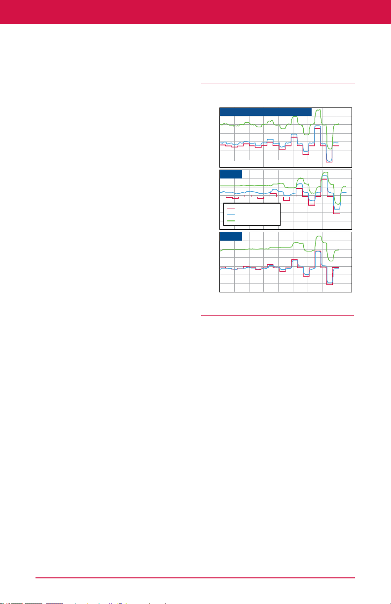
Control Valve Handbook | Chapter 2: Control Valve Performance
Time (seconds)
See Additional Resources »
a complete assembly typically do not
yield the best dynamic performance.
Some of the most important design
considerations include:
Deadband
Actuator/positioner design
Valve response time
Valve type and characterization
Valve sizing
Each of these design features will be
considered in this chapter to provide
insight into what constitutes a superior
valve design.
2.1.1 Deadband
Deadband is a major contributor to
excess process variability. Control valve
assemblies can be a primary source of
deadband in an instrumentation loop
due to a variety of causes such as
friction, backlash, shaft wind-up, relay or
spool valve dead zone, etc.
Deadband is a general phenomenon
where a range or band of controller
output (CO) values fail to produce a
change in the measured process variable
(PV) when the input signal reverses
direction. When a load disturbance
occurs, the process variable (PV)
deviates from the set point. This
deviation initiates a corrective action
through the controller and back through
the process. However, an initial change
in controller output can produce no
corresponding corrective change in the
process variable. Only when the
controller output has changed enough
to progress through the deadband does
a corresponding change in the process
variable occur.
Any time the controller output reverses
direction, the controller signal must pass
through the deadband before any
corrective change in the process variable
will occur. The presence of deadband in
the process ensures the process variable
deviation from the set point will have to
increase until it is big enough to get
through the deadband. Only then can a
corrective action occur.
4” Segmented Ball Valves with Metal Seals,
Diaphragm Actuators and Standard Positioners
Valve A (FisherTM V150HD/1052(33)/3610J)
65
60
55
%
50
45
40
0.5%
Valve B
65
60
55
%
50
Input Signal
45
Actuator Position
Flow Rate (Filtered)
40
Valve C
65
60
55
%
50
45
40
0 50 100 150 200 250 300 350 400
Figure 2.3 Effect of Deadband on Valve Performance
5% 10%2% STEP1%
2.1.1.1 Causes of Deadband
Deadband has many causes, but friction
and backlash in the control valve, along
with shaft wind-up in rotary valves, and
relay dead zone are some of the more
common forms. Because most control
actions for regulatory control consist of
small changes (1% or less), a control
valve with excessive deadband might
not even respond to many of these small
changes. A well-engineered valve should
respond to signals of 1% or less to
provide effective reduction in process
variability. However, it is not uncommon
for some valves to exhibit deadband as
great as 5% or more. In a recent plant
audit, 30% of the valves had deadbands
in excess of 4%. Over 65% of the loops
audited had deadbands greater than 2%.
35
Page 36

Control Valve Handbook | Chapter 2: Control Valve Performance
2.1.1.2 Effects of Deadband
Figure 2.3 shows just how dramatic the
combined effects of deadband can be.
This diagram represents an open-loop
test of three different control valves
under normal process conditions. The
valves are subjected to a series of step
inputs which range from 0.5% to 10%.
Step tests under owing conditions are
essential because they allow the
performance of the entire valve
assembly to be evaluated, rather than
just the valve actuator assembly as
would be the case under most bench
test conditions.
2.1.1.3 Performance Tests
Some performance tests on a valve
assembly compare only the actuator
stem travel versus the input signal. This
is misleading because it ignores the
performance of the valve itself.
It is critical to measure dynamic
performance of a valve under owing
conditions so the change in process
variable can be compared to the change
in valve assembly input signal. It
matters little if only the valve stem
changes in response to a change in
valve input because if there is no
corresponding change in the controlled
variable, there will be no correction to
the process variable.
In all three valve tests (Figure 2.3), the
actuator stem motion changes fairly
faithfully in response to the input signal
changes. On the other hand, there is a
dramatic difference in each of the valve’s
ability to change the ow in response to
an input signal change.
For Valve A, the process variable (ow
rate) responds well to input signals as
low as 0.5. Valve B requires input signal
changes as great as 5% before it begins
responding faithfully to each of the input
signal steps. Valve C is considerably
worse, requiring signal changes as great
as 10% before it begins to respond
faithfully to each of the input signal
steps. The ability of either Valve B or C to
improve process variability is very poor.
2.1.1.4 Friction
Friction is a major cause of deadband in
control valves. Rotary valves are often
very susceptible to friction caused by the
high seat loads required to obtain shutoff
with some seal designs. Because of the
high seal friction and poor drive train
stiffness, the valve shaft winds up and
does not translate motion to the control
element. As a result, an improperly
designed rotary valve can exhibit
signicant deadband that clearly has a
detrimental effect on process variability.
Manufacturers usually lubricate rotary
valve seals during manufacture, but
after only a few hundred cycles this
lubrication wears off. In addition,
pressure-induced loads also cause seal
wear. As a result, the valve friction can
increase by 400% or more for some valve
designs. This illustrates the misleading
performance conclusions that can result
from evaluating products using benchtype data before the torque has
stabilized. Valves B and C (Figure 2.3)
show the devastating effect these higher
friction torque factors can have on a
valve’s performance.
Packing friction is the primary source of
friction in sliding-stem valves. In these
types of valves, the measured friction
can vary signicantly between valve
styles and packing arrangements.
Actuator style also has a profound impact
on control valve assembly friction.
Generally, spring-and-diaphragm
actuators contribute less friction to the
control valve assembly than piston
actuators. An additional advantage of
spring-and-diaphragm actuators is that
their frictional characteristics are more
uniform with age. Piston actuator friction
36
Page 37

Control Valve Handbook | Chapter 2: Control Valve Performance
See Additional Resources »
probably will increase signicantly with
use as guide surfaces and as the O-rings
wear, lubrication fails, and the elastomer
degrades. Thus, to ensure continued
good performance, maintenance is
required more often for piston actuators
than for spring-and-diaphragm actuators.
If that maintenance is not performed,
process variability can suffer dramatically
without the operator’s knowledge.
Backlash results in a discontinuity of
motion when the device changes
direction. Backlash commonly occurs in
gear drives of various congurations.
Rack-and-pinion actuators are
particularly prone to deadband due to
backlash. Some valve shaft connections
also exhibit deadband effects. Spline
connections generally have much less
deadband than keyed shafts or
double-D designs.
While friction can be reduced
signicantly through good valve design,
it is a difcult phenomenon to eliminate
entirely. A well-engineered control valve
should be able to virtually eliminate
deadband due to backlash and shaft
wind-up.
For best performance in reducing process
variability, the total deadband for the
entire valve assembly should be 1% or
less. Ideally, it should be as low as 0.25%.
2.1.2 Actuator and Positioner Design
Actuator and positioner design must be
considered together. The combination
of these two pieces of equipment
greatly affects the static performance
(deadband), as well as the dynamic
response of the control valve assembly
and the overall air consumption of the
valve instrumentation.
Positioners are used with the majority of
control valve applications specied
today. Positioners allow for precise valve
assembly response, as well as online
diagnostics when used with a
conventional digital control system. With
the increasing emphasis upon economic
performance of process control,
positioners should be considered for
every valve application where process
optimization is important.
A positioner can be thought of as a high
proportional gain device. When
combined with an actuator and valve, the
assembly will ideally behave like a rst
order or underdamped second order
system, depending on use and intended
performance. A digital valve controller
has additional tuning parameters, such as
derivative gain, which largely exist to
remove undesirable characteristics and
further tune the assembly to the desired
performance. Many positioners also
include an integral capability to remove
any offsets between valve set point and
position. Under most process control
situations, this feature can be turned off
to avoid the possibility of forming slow
process oscillations, as the offset between
valve position and set point is typically
handled by the process controller.
Once a change in the set point has been
detected by the positioner, the
positioner must be capable of supplying
a large volume of air to the actuator,
making the assembly move in a timely
and controlled action. This ability comes
from the high-gain positioner and is a
function of integrated pneumatic
booster within the positioner. This
pneumatic booster is typically
comprised of a relay or spool valve.
Typical high-performance, two-stage
positioners use pneumatic relays. Relays
are preferred because they can provide
high gain that gives excellent dynamic
performance with low steady-state air
consumption. In addition, they are less
subject to uid contamination. In
addition, some large or high-friction
actuators may use additional external
boosters to meet specications, such as
37
Page 38

Control Valve Handbook | Chapter 2: Control Valve Performance
stroking speed.
Positioner designs are continuing to
improve by decreasing air consumption
and advancing the diagnostic
capabilities accessible to users. In
addition, features have been added to
support advancing industry safety
requirements such as safety
instrumented systems (SIS) and
optimized digital valves.
2.1.3 Valve Response Time
For optimum control of many processes,
it is important that the valve reach a
specic position quickly. A quick
response to small signal changes (1% or
less) is one of the most important factors
in providing optimum process control. In
automatic, regulatory control, the bulk
of the signal changes received from the
controller are for small changes in
position. If a control valve assembly can
quickly respond to these small changes,
process variability will be improved.
Valve response time is measured by a
parameter called T63. T63 is the time
measured from initiation of the input
signal change to when the output
reaches 63% of the corresponding
change. It includes both the valve
assembly dead time, which is a static
time, and the dynamic time of the valve
assembly. The dynamic time is a measure
of how long the actuator takes to get to
the 63% point once it starts moving.
2.1.3.1 Dead Time
Deadband, whether it comes from
friction in the valve body and actuator or
from the positioner, can signicantly
affect the dead time of the valve
assembly. It is important to keep the
dead time as small as possible, as this
can be a limiting factor for process
stability. Generally, dead time should be
no more than one-third of the overall
valve response time. However, the
relative relationship between the dead
time and the process time constant is
critical. If the valve assembly is in a fast
loop where the process time constant
approaches the dead time, the dead
time can dramatically affect loop
performance. On these fast loops, it is
critical to select control equipment with
dead time as small as possible.
Also, from a loop tuning point of view, it is
important that the dead time be relatively
consistent in both stroking directions of
the valve. Some valve assembly designs
can have dead times that are three to ve
times longer in one stroking direction
than the other. This type of behavior is
typically induced by the asymmetric
behavior of the positioner design, and it
can severely limit the ability to tune the
loop for best overall performance.
2.1.3.2 Dynamic Time
Once the dead time has passed and the
valve begins to respond, the remainder of
the valve response time comes from the
dynamic time of the valve assembly. This
dynamic time will be determined
primarily by the dynamic characteristics
of the positioner and actuator
combination. These two components
must be carefully matched to minimize
the total valve response time. In a
pneumatic valve assembly, for example,
the positioner must have a gain to
minimize the dynamic time of the valve
assembly. This gain comes mainly from
the power amplier stage in the
positioner. In other words, the faster the
positioner relay or spool valve can supply
a large volume of air to the actuator, the
faster the valve response time will be.
However, this high-gain power amplier
will have little effect on the dead time
unless it has some intentional deadband
designed into it to reduce static air
consumption. Of course, the design of the
actuator signicantly affects the dynamic
time. For example, the greater the volume
of the actuator air chamber to be lled,
the slower the valve response time.
38
Page 39

Control Valve Handbook | Chapter 2: Control Valve Performance
See Additional Resources »
Valve Response Time
Step Size T(d) Seconds T63 Seconds
ENTECH SPEC. 4” VALVE SIZE % s0.2 s0.6
Valve A (Fisher V150HD/1052(33)/3610J)
Valve Action: Opening 2 0.25 0.34
Valve Action: Closing -2 0.50 0.74
Valve Action: Opening 5 0.16 0.26
Valve Action: Closing -5 0.22 0.42
Valve Action: Opening 10 0.19 0.33
Valve Action: Closing -10 0.23 0.46
Valve B
Valve Action: Opening 2 5.61 7.74
Valve Action: Closing -2 0.46 1.67
Valve Action: Opening 5 1.14 2.31
Valve Action: Closing -5 1.04 2
Valve Action: Opening 10 0.42 1.14
Valve Action: Closing -10 0.41 1.14
Valve C
Valve Action: Opening 2 4.4 5.49
Valve Action: Closing -2 NR NR
Valve Action: Opening 5 5.58 7.06
Valve Action: Closing -5 2.16 3.9
Valve Action: Opening 10 0.69 1.63
Valve Action: Closing -10 0.53 1.25
NR = No Response
Figure 2.4 Valve Response Time Summary
2.3.1.3 Solutions
At rst, it might appear that the solution
would be to minimize the actuator
volume and maximize the positioner
dynamic power gain, but it is really not
that easy. This can be a dangerous
combination of factors from a stability
point of view. Recognizing that the
positioner/actuator combination is its
own feedback loop, it is possible to
make the positioner/actuator loop gain
too high for the actuator design being
used, causing the valve assembly to go
into an unstable oscillation. In addition,
reducing the actuator volume has an
adverse affect on the thrust-to-friction
ratio, which increases the valve
assembly deadband, resulting in
increased dead time.
If the overall thrust-to-friction ratio is
not adequate for a given application,
one option is to increase the thrust
capability of the actuator by using the
next size actuator or by increasing the
39
Page 40

Control Valve Handbook | Chapter 2: Control Valve Performance
pressure to the actuator. This higher-tofriction ratio reduces deadband, which
should help to reduce the dead time of
the assembly. However, both of these
alternatives mean that a greater volume
of air needs to be supplied to the
actuator. The trade off is a possible
detrimental effect on the valve response
time through increased dynamic time.
One way to reduce the actuator air
chamber volume is to use a piston
actuator rather than a spring-anddiaphragm actuator, but this is not a
panacea. Piston actuators usually have
higher thrust capability than spring-anddiaphragm actuators, but they also have
higher friction, which can contribute to
problems with valve response time. To
obtain the required thrust with a piston
actuator, it is usually necessary to use a
higher air pressure than with a
diaphragm actuator, because the piston
typically has a smaller area. This means
that a larger volume of air needs to be
supplied with its attendant ill effects on
the dynamic time. In addition, piston
actuators, with their greater number of
guide surfaces, tend to have higher
friction due to inherent difculties in
alignment, as well as friction from the
O-ring. These friction problems also
tend to increase over time. Regardless of
how good the O-rings are initially, these
elastomeric materials will degrade with
time due to wear and other
environmental conditions. Likewise,
wear on the guide surfaces will increase
the friction, and depletion of the
lubrication will occur. These friction
problems result in a greater piston
actuator deadband, which will increase
the valve response time through
increased dead time.
2.3.1.4 Supply Pressure
Instrument supply pressure can also
have a signicant impact on dynamic
performance of the valve assembly. For
example, it can dramatically affect the
positioner gain, as well as overall air
consumption.
Fixed-gain positioners have generally
been optimized for a particular supply
pressure. This gain, however, can vary by
a factor of two or more over a small
range of supply pressures. For example,
a positioner that has been optimized for
a supply pressure of 20 psig might nd
its gain cut in half when the supply
pressure is boosted to 35 psig.
Supply pressure also affects the volume
of air delivered to the actuator, which
determines speed. It is also directly linked
to air consumption. Again, high-gain
spool valve positioners can consume up
to ve times the amount of air required
for more efcient high-performance,
two-stage positioners that use relays for
the power amplication stage.
2.3.1.5 Minimizing Dead Time
To minimize the valve assembly dead
time, minimize the deadband of the
valve assembly, whether it comes from
friction in the valve seal design, packing
friction, shaft wind-up, actuator, or
positioner design. As indicated, friction
is a major cause of deadband in control
valves. On rotary valve styles, shaft
wind-up can also contribute signicantly
to deadband. Actuator style also has a
profound impact on control valve
assembly friction. Generally, spring-anddiaphragm actuators contribute less
friction to the control valve assembly
than piston actuators over an extended
time. As mentioned, this is caused by
the increasing friction from the piston
O-ring, misalignment problems, and
failed lubrication.
Having a positioner design with high
gain can make a signicant difference in
reducing deadband. This can also make
a signicant improvement in the valve
assembly resolution. Valve assemblies
40
Page 41

Control Valve Handbook | Chapter 2: Control Valve Performance
See Additional Resources »
with deadband and resolution of 1% or
less are no longer adequate for many
process variability reduction needs.
Many processes require the valve
assembly to have deadband and
resolution as low as 0.25%, especially
where the valve assembly is installed in a
fast process loop.
2.3.1.6 Valve Response Time
One of the surprising things to come out
of many industry studies on valve
response time has been the change in
thinking about spring-and-diaphragm
actuators versus piston actuators. It has
long been a misconception in the
process industry that piston actuators
are faster than spring-and-diaphragm
actuators. Research has shown this to be
untrue for small signal changes.
This mistaken belief arose from many
years of experience with testing valves
for stroking time. A stroking time test is
normally conducted by subjecting the
valve assembly to a 100% step change in
the input signal and measuring the time
it takes the valve assembly to complete
its full stroke in either direction.
Although piston-actuated valves usually
do have faster stroking times than most
spring-and-diaphragm actuated valves,
this test does not indicate valve
performance in a typical process control
situation where in normal process control
applications, the valve is rarely required
to stroke through its full operating range.
Typically, the valve is only required to
respond within a range of 0.25% to 2%
change in valve position. Extensive
testing of valves has shown that springand-diaphragm valve assemblies
consistently outperform piston actuated
valves on small signal changes, which are
more representative of regulatory
process control applications. Higher
friction in the piston actuator is one
factor that plays a role in making them
less responsive to small signals than
spring-and-diaphragm actuators.
Selecting the proper valve, actuator, and
positioner combination is not easy. It is
not simply a matter of nding a
combination that is physically
compatible. Good engineering
judgment must go into the practice of
valve assembly sizing and selection to
achieve the best dynamic performance
from the loop.
Figure 2.4 shows the dramatic
differences in dead time and overall T63
response time caused by differences in
valve assembly design.
2.1.4 Valve Type and Characterization
The style of valve used and the sizing of
the valve can have a large impact on the
performance of the control valve
assembly in the system. While a valve
must be of sufcient size to pass the
required ow under all possible
contingencies, a valve that is too large
for the application is a detriment to
process optimization.
Flow capacity of the valve is also related
to the style of valve through the inherent
characteristic of the valve. The inherent
characteristic is the relationship between
the valve ow capacity and the valve
travel when the differential pressure
drop across the valve is held constant.
Typically, these characteristics are
plotted on a curve where the horizontal
axis is labeled in percent travel although
the vertical axis is labeled as percent
ow (or C
of both the valve travel and the pressure
drop across the valve, it is traditional to
conduct inherent valve characteristic
tests at a constant pressure drop. This is
not a normal situation in practice, but it
provides a systematic way of comparing
one valve characteristic design to
another.
). Since valve ow is a function
v
41
Page 42

Control Valve Handbook | Chapter 2: Control Valve Performance
Under the specic conditions of constant
pressure drop, the valve ow becomes
only a function of the valve travel and
the inherent design of the valve trim.
These characteristics are called the
inherent ow characteristic of the valve.
Typical valve characteristics conducted
in this manner are named linear,
equal-percentage, and quick-opening.
The ratio of the incremental change in
valve ow (output) to the corresponding
increment of valve travel (input) which
caused the ow change is dened as the
valve gain.
Inherent Valve Gain = (Change in
Flow)/(Change in Travel) = Slope of the
Inherent Characteristic Curve
The linear characteristic has a constant
inherent valve gain throughout its range,
and the quick-opening characteristic has
an inherent valve gain that is the
greatest at the lower end of the travel
range. The greatest inherent valve gain
for the equal-percentage valve is at the
largest valve opening.
Inherent valve characteristic is an
inherent function of the valve ow
passage geometry and does not change
as long as the pressure drop is held
constant. Many valve designs,
particularly rotary ball valves, buttery
valves, and eccentric plug valves, have
inherent characteristics, which cannot
be easily changed. However, most globe
valves have a selection of valve cages or
plugs that can be interchanged to
modify the inherent ow characteristic.
Knowledge of the inherent valve
characteristic is useful, but the more
important characteristic for purposes of
process optimization is the installed ow
characteristic of the entire process,
including the valve and all other
equipment in the loop. The installed ow
characteristic is dened as the
relationship between the ow through
the valve and the valve assembly input
when the valve is installed in a specic
system, and the pressure drop across the
valve is allowed to change naturally,
rather than being held constant. An
illustration of such an installed ow
characteristic is shown in the upper
1000
Installed Characteristic
800
Flow
(gpm)
Gain
600
400
200
0
3
2
(% Flow /
% Input)
Figure 2.5 Installed Flow Characteristic and Gain
42
1
Installed Gain
0
10 20 30 40 50 60 70 80 90 100
Valve Travel (%)
Control Range
EnTec Gain
Specification
Page 43

Control Valve Handbook | Chapter 2: Control Valve Performance
See Additional Resources »
curve of Figure 2.5. The ow in this gure
is related to the more familiar valve travel
rather than valve assembly input.
2.1.4.1 Installed Gain
Installed gain, shown in the lower curve
of Figure 2.5, is a plot of the slope of the
upper curve at each point. Installed ow
characteristic curves can be obtained
under laboratory conditions by placing
the entire loop in operation at some
nominal set point and with no load
disturbances. The loop is placed in
manual operation, and the ow is then
measured and recorded as the input to
the control valve assembly is manually
driven through its full travel range. A
plot of the results is the installed ow
characteristic curve shown in the upper
part of Figure 2.5. The slope of this ow
curve is then evaluated at each point on
the curve and plotted as the installed
gain as shown in the lower part of
Figure 2.5.
Field measurements of the installed
process gain can also be made at a single
operating point using open-loop step
tests (Figure 2.3). The installed process
gain at any operating condition is simply
the ratio of the percent change in output
(ow) to the percent change in valve
assembly input signal.
The reason for characterizing inherent
valve gain through various valve trim
designs is to provide compensation for
other gain changes in the control loop.
The end goal is to maintain a loop gain,
which is reasonably uniform over the
entire operating range, to maintain a
relatively linear installed ow
characteristic for the process. Because of
the way it is measured, the installed ow
characteristic and installed gain
represented in Figure 2.5 are really the
installed gain and ow characteristic for
the entire process.
Typically, the gain of the unit being
controlled changes with ow. For
example, the gain of a pressure vessel
tends to decrease with throughput. In
this case, the process control engineer
would then likely want to use an
equal-percentage valve that has an
increasing gain with ow. Ideally, these
two inverse relationships should balance
out to provide a more linear installed
ow characteristic for the entire process.
2.1.4.2 Loop Gain
Theoretically, a loop has been tuned for
optimum performance at some set point
ow condition. As the ow varies about
that set point, it is desirable to keep the
loop gain as constant as possible to
maintain optimum performance. If the
loop gain change, due to the inherent
valve characteristic, does not exactly
compensate for the changing gain of the
unit being controlled, then there will be
a variation in the loop gain due to
variation in the installed process gain. As
a result, process optimization becomes
more difcult. There is also a danger that
the loop gain might change enough to
cause instability, limit cycling, or other
dynamic difculties.
Loop gain should not vary more than
4:1; otherwise, the dynamic
performance of the loop suffers
unacceptably. There is nothing magic
about this specic ratio; it is simply one
which many control practitioners agree
produces an acceptable range of gain
margins in most process control loops.
This guideline forms the basis for the
following EnTech gain limit specication
(from Control Valve Dynamic Specication,
Version 3.0, November 1998, EnTech
Control Inc., Toronto, Ontario, Canada):
Loop Process Gain = 1.0 (% of
Transmitter Span)/(% Controller Output)
Nominal Range: 0.5-2.0
(Note 4-to-1 Ratio)
43
Page 44
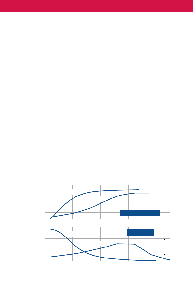
Control Valve Handbook | Chapter 2: Control Valve Performance
Installed Flow Characteristic and Gain
This denition of the loop process
includes all the devices in the loop
conguration except the controller. In
other words, the product of the gains of
such devices as the control valve
assembly, the heat exchanger, pressure
vessel, or other system being controlled,
the pump, the transmitter, etc. is the
process gain. Because the valve is part of
the loop process as dened here, it is
important to select a valve style and size
that will produce an installed ow
characteristic that is sufciently linear to
stay within the specied gain limits over
the operating range of the system. If too
much gain variation occurs in the control
valve itself, it leaves less exibility in
adjusting the controller. It is good
practice to keep as much of the loop
gain in the controller as possible.
Although the 4:1 ratio of gain change in
the loop is widely accepted, not
everyone agrees with the 0.5 to 2.0 gain
limits. Some industry experts have made
a case for using loop process gain limits
from 0.2 to 0.8, which is still 4:1. The
potential danger inherent in using this
reduced gain range is that the low end of
the gain range could result in large valve
swings during normal operation. It is
good operating practice to keep valve
swings below about 5%. However, there
is also a danger in letting the gain get too
large. The loop can become oscillatory or
even unstable if the loop gain gets too
high at some point in the travel. To
ensure good dynamic performance and
loop stability over a wide range of
operating conditions, industry experts
recommend that loop equipment be
engineered so the process gain remains
within the range of 0.5 to 2.0.
2.1.4.3 Process Optimization
Process optimization requires a valve
style and size be chosen that will keep
the process gain within the selected gain
limit range over the widest possible set
of operating conditions. Because
minimizing process variability is so
dependent on maintaining a uniform
installed gain, the range over which a
valve can operate within the acceptable
gain specication limits is known as the
control range of the valve.
The control range of a valve varies
1000
800
Flow
600
(gpm)
400
200
0
3
Gain
(% Flow /
% Input)
Figure 2.6 Effect of Valve Style on Control Range
44
2
1
0
10 20 30 40 50 60 70 80 90 100
Butterfly
Butterfly
Globe
Globe
Valve Travel (%)
Installed Characteristic
Installed Gain
EnTec Gain
Specification
Page 45

Control Valve Handbook | Chapter 2: Control Valve Performance
See Additional Resources »
dramatically with valve style. Figure 2.6
shows a line-size buttery valve
compared to a line-size globe valve. The
globe valve has a much wider control
range than the buttery valve. Other
valve styles, such as V-notch ball valves
and eccentric plug valves generally fall
somewhere between these two ranges.
Because buttery valves typically have
the narrowest control range, they are
generally best suited for xed-load
applications. In addition, they must be
carefully sized for optimal performance
at xed loads.
If the inherent characteristic of a valve
could be selected to exactly compensate
for the system gain change with ow,
one would expect the installed process
gain (lower curve) to be essentially a
straight line at a value of 1.0.
Unfortunately, such a precise gain match
is seldom possible due to the logistical
limitations of providing an innite
variety of inherent valve trim
characteristics. In addition, some valve
styles, such as buttery and ball valves,
do not offer trim alternatives that allow
easy change of the inherent valve
characteristic.
This condition can be alleviated by use of
non-linear scaling between valve set
point and position. This technique
recalibrates the valve input signal by
taking the linear controller signal and
using a pre-programmed table of values
to produce the valve input required to
achieve the desired valve characteristic.
This technique is sometimes referred to
as forward path or set point
characterization.
This characterization occurs outside the
positioner feedback loop, and avoids
changing the positioner loop gain. This
method also has its dynamic limitations.
For example, there can be places in a
valve range where a 1.0% process signal
change might be narrowed through this
characterization process to only a 0.1%
signal change to the valve (that is, in the
at regions of the characterizing curve).
Many control valves are unable to
respond to signal changes this small.
The best process performance occurs
when the required ow characteristic is
obtained through changes in the valve
trim rather than through use of nonlinear characterization. Proper selection
of a control valve designed to produce a
reasonably linear installed ow
characteristic over the operating range
of the system is a critical step in ensuring
optimum process performance.
2.1.5 Valve Sizing
Oversizing of valves sometimes occurs
when trying to optimize process
performance through a reduction of
process variability. This results from
using line-size valves, especially with
high-capacity rotary valves, as well as
the conservative addition of multiple
safety factors at different stages in the
process design.
Oversizing the valve hurts process
variability in two ways. First, the
oversized valve puts too much gain in
the valve, leaving less exibility in
adjusting the controller. Best
performance results when most loop
gain comes from the controller.
Notice in the gain curve of Figure 2.5,
the process gain gets quite high in the
region below about 25% valve travel. If
the valve is oversized, making it more
likely to operate in or near this region,
this high gain can likely mean that the
controller gain will need to be reduced
to avoid instability problems with the
loop. This, of course, will mean a penalty
of increased process variability.
The second way oversized valves hurt
process variability is that an oversized
valve is likely to operate more frequently
at lower valve openings where seal
45
Page 46

Control Valve Handbook | Chapter 2: Control Valve Performance
friction can be greater, particularly in
rotary valves. Because an oversized valve
produces a disproportionately large ow
change for a given increment of valve
travel, this phenomenon can greatly
exaggerate the process variability
associated with deadband due to friction.
Regardless of its actual inherent valve
characteristic, a severely oversized valve
tends to act more like a quick-opening
valve, which results in high installed
process gain in the lower lift regions
(Figure 2.5). In addition, when the valve
is oversized, the valve tends to reach
system capacity at relatively low travel,
making the ow curve atten out at
higher valve travels (Figure 2.5). For
valve travels above about 50 degrees,
this valve has become totally ineffective
for control purposes because the
process gain is approaching zero and the
valve must undergo wide changes in
travel with very little resulting changes
in ow. Consequently, there is little hope
of achieving acceptable process
variability in this region.
The valve shown in Figure 2.5 is totally
misapplied in this application because it
has such a narrow control range
(approximately 25 degrees to 45
degrees). This situation came about
because a line-sized buttery valve was
chosen, primarily due to its low cost, and
no consideration was given to the lost
prot that results from sacricing
process variability through poor dynamic
performance of the control valve.
Unfortunately, this situation is often
repeated. Process control studies show
that, for some industries, the majority of
valves currently in process control loops
are oversized for the application. While it
might seem counterintuitive, it often
makes economic sense to select a control
valve for present conditions and then
replace the valve when conditions change.
When selecting a valve, it is important to
consider the valve style, inherent
characteristic, and valve size that will
provide the broadest possible control
range for the application.
Refer to Chapter 5 for more sizing
information.
2.2 Economic Results
Consideration of the factors discussed in
this chapter can have a dramatic impact
on the economic results of an operating
plant. More and more control valve users
focus on dynamic performance
parameters such as deadband, response
times, and installed gain (under actual
process load conditions) as a means to
improve process loop performance.
Although it is possible to measure many
of these dynamic performance
parameters in an open loop situation,
the impact these parameters have
becomes clear when closed-loop
performance is measured. The closedloop test results shown in Figure 2.7
demonstrate the ability of three different
valves to reduce process variability over
different tuning conditions.
This diagram plots process variability as
a percent of the set point variable versus
the closed-loop time constant, which is
a measure of loop tuning.
The horizontal line labeled “Manual”,
shows how much variability is inherent
in the loop when no attempt is made to
control it (open loop). The line sloping
downward to the left marked
“Minimum Variability” represents the
calculated dynamic performance of an
ideal valve assembly (one with no
non-linearities). All real valve assemblies
should normally fall somewhere
between these two conditions.
Not all valves provide the same dynamic
performance even though they all
theoretically meet static performance
purchase specications and are
46
Page 47

Control Valve Handbook | Chapter 2: Control Valve Performance
See Additional Resources »
4” Valves Tested at 600 gpm in 4” Test Loop
6
5
4
Variability,
2
(%)
Figure 2.7 Closed Loop Random Load Disturbance Summary
3
2
1
Faster Tuning Slower Tuning
0
Manual
Auto
1 10
Closed-Loop Time Constant, (seconds)
Valve A
Valve B
Valve C
Minimum
Variability
considered to be equivalent valves
(Figure 2.7). Valve A in Figure 2.7 does a
good job of following the trend of the
minimum variability line over a wide
range of controller tunings. This valve
shows excellent dynamic performance
with minimum variability. In contrast,
Valves B and C designs don’t fare as well
and increase in variability as the system
is tuned more aggressively for
decreasing closed-loop time constants.
All three valve designs are capable of
controlling the process and reducing the
variability, but two designs don’t do it as
well. Consider what would happen if the
poorer performing Valve B was replaced
with the best performing Valve A, and
the system was tuned to a 2.0 second
closed-loop time constant.
The test data shows this would result in
a 1.4% improvement in process
variability. This might not seem like
much, but the results over a time can be
impressive. A valve that can provide this
much improvement every minute of
every day can save signicant dollars
over a single year.
The performance of the better valve in
this example provides strong evidence
that a superior control valve assembly can
have a profound economic impact. This
example is only one way a control valve
can increase prots through tighter
control. Decreased energy costs,
increased throughput, less reprocessing
cost for out-of-specication product, and
so on, are all ways a good control valve
can increase economic results through
tighter control. While the initial cost
might be higher for the best control valve,
the few extra dollars spent on a wellengineered control valve can dramatically
increase the return on investment. Often
the extra initial cost of the valve can be
paid for in a matter of days.
As a result, the process industries have
become increasingly aware that control
valve assemblies play an important role
in loop/unit/plant performance. They
have also realized that traditional
47
Page 48

Control Valve Handbook | Chapter 2: Control Valve Performance
methods of specifying a valve assembly
are no longer adequate to ensure the
benets of process optimization. While
important, such static performance
indicators as ow capacity, leakage,
materials compatibility, and bench
performance data are not sufciently
adequate to deal with the dynamic
characteristics of process control loops.
2.3 Summary
The control valve assembly plays an
extremely important role in producing
the best possible performance from the
control loop. Process optimization
means optimizing the entire process,
not just the control algorithms used in
the control room equipment. The valve
is called the nal control element
because the control valve assembly is
where process control is implemented. It
makes no sense to install an elaborate
process control strategy and hardware
instrumentation system capable of
achieving 0.5% or better process control
and then to implement that control
strategy with a 5% or worse control
valve. Audits performed on thousands of
process control loops have provided
strong proof that the nal control
element plays a signicant role in
achieving true process optimization.
Protability increases when a control
valve has been properly engineered for
its application.
Control valves are sophisticated,
high-tech products and should not be
treated as a commodity. Although
traditional valve specications play an
important role, valve specications must
also address real dynamic performance
characteristics if true process
optimization is to be achieved. It is
imperative that these specications
include such parameters as deadband,
dead time, response time, etc.
Finally, process optimization begins and
ends with optimization of the entire
loop. Parts of the loop cannot be treated
individually to achieve coordinated loop
performance. Likewise, performance of
any part of the loop cannot be evaluated
in isolation. Isolated tests under nonloaded, bench-type conditions will not
provide performance information that is
obtained from testing the hardware
under actual process conditions.
48
Page 49

Control Valve Handbook | Chapter 2: Control Valve Performance
See Additional Resources »
49
Page 50

Chapter 3
Valve and Actuator Types
Page 51

Control Valve Handbook | Chapter 3: Valve and Actuator Types
See Additional Resources »
3.1 Control Valve Styles
The control valve regulates the rate of
uid ow as the position of the valve
closure member is changed by force from
the actuator. To do this, the valve must:
Contain the uid without external
leakage;
Have adequate capacity for the
intended service;
Be capable of withstanding the
erosive, corrosive, and temperature
inuences of the process; and
Incorporate appropriate end
connections to mate with adjacent
pipelines and actuator attachment
means to permit transmission of
actuator thrust to the valve stem
or shaft.
Many styles of control valve bodies have
been developed through the years. Some
have found wide application, while others
meet specic service conditions and are
used less frequently. The following
summary describes some popular control
valve body styles in use today.
n
change the ow characteristic or
provide reduced-capacity ow, noise
attenuation, or reduction or
elimination of cavitation.
Angle valves (Figure 3.1) are
commonly used in boiler feedwater
and heater drain service and in
piping schemes where space is at a
premium and the valve can also
serve as an elbow. The valve shown
has cage-style construction. Others
might have expanded outlet
connections, restricted trim, or
outlet liners for reduction of erosion,
ashing, or cavitation damage.
3.1.1 Globe Valves
3.1.1.1 Single-Port Valve Bodies
Single port is the most common
valve body style and is simple in
construction.
Single-port valves are available in
various forms, such as globe, angle,
bar stock, forged, and split
constructions.
Many single-seated valve bodies use
cage or retainer-style construction to
retain the seat-ring, provide valve
plug guiding, and provide a means
for establishing particular valve ow
characteristics.
Cage or retainer-style single-seated
valve bodies can also be easily
modied by change of trim parts to
Figure 3.1 Flanged Angle-Style Control Valve Body
Alloy valve bodies are often specied
for corrosive applications (see Figure
3.2). They can be made from bar
stock, castings, or, forgings. When
exotic metal alloys are required for
corrosion resistance, sometimes a
bar stock valve body is less expensive
than a cast valve body. A valve with a
polymer liner may also be used.
High-pressure valves are often used
in the hydrocarbon and power
industries and are available to
CL4500 or API 10,000. These can be
globe or angle designs and typically
have optional specialized trim for
51
Page 52

Control Valve Handbook | Chapter 3: Valve and Actuator Types
severe service applications.
High-pressure stem-guided globe
valves are often used in production of
gas and oil. Variations available include
a threaded bonnet and self-draining
angle. Flanged versions are available
with ratings to Class 2500.
3.1.1.2 Post- and Port-Guided Valve Bodies
Generally specied for applications
with stringent shutoff requirements.
They use metal-to-metal seating
surfaces or soft seating with PTFE or
other composition materials forming
the seal. They can handle most
service requirements.
Because high-pressure uid is
normally loading the entire area of
the port, the unbalanced force
created must be considered in
selecting actuators for post- and
port-guided control valve bodies.
Although most popular in the smaller
sizes, post- and port-guided valves
can often be used in NPS 4-8 (DN
100-200) sizes with high-thrust
actuators.
They can be susceptible to highpressure drop vibration, so care is
needed with the design to avoid this.
Figure 3.3 shows one of the more popular
styles of post-guided globe-type control
valve bodies. They are widely used in
process control applications, particularly
in NPS 1-4 (DN 20-100).
Normal ow direction is most often up
through the seat ring.
3.1.1.3 Cage-Style Valve Bodies
Cage-style trim (Figure 3.4) provides
valve plug guiding, seat ring retention,
and ow characterization.
In addition, a variety of seal materials
and styles are available to seal between
the upper portion of the valve plug’s
outer diameter and the cage bore to
limit leakage of the upstream, high-
pressure uid into the lower pressure
downstream system. In balanced
designs, downstream pressure acts on
both the top and bottom sides of the
valve plug, which nullies most of the
static unbalanced force. Reduced
unbalanced force permits operation of
the valve with smaller actuators than
those necessary for unbalanced valve
trim. Interchangeability of trim permits
choice of several ow characteristics,
noise attenuation, anti-cavitation, or
Figure 3.2 Bar Stock Valve Body
52
Figure 3.3. Single-Ported Globe-Style Valve Body
Page 53

Control Valve Handbook | Chapter 3: Valve and Actuator Types
See Additional Resources »
other severe service capability. For most
available trim designs, the standard
direction of ow is in through the cage
openings and down through the seat
ring. However, noise attenuation trim is
typically ow up. These are available in
various material combinations, sizes
through NPS 36 (DN 900), and pressure
ratings up to Class 4500 or API 10,000.
3.1.1.4 Double-Ported Valve Bodies
The industry has predominantly
moved away from using doubleported valve designs.
Dynamic force on the plug tends to
be balanced as ow tends to open
one port and close the other.
Reduced dynamic forces acting on the
plug might permit choosing a smaller
actuator than would be necessary for
a single-ported unbalanced valve
body with similar capacity.
Bodies are usually furnished only in
NPS 4 (DN 100) or larger.
Bodies normally have higher capacity
than single-ported valves of the
same line size.
Many double-ported bodies reverse,
so the valve plug can be installed as
either push-down-to-open or
push-down-to-close (Figure 3.5).
Metal-to-metal seating usually
provides Class II shutoff capability,
although Class III capability is also
possible.
Port-guided valve plugs are often
used for on/off or low-pressure
throttling service. Top- and bottomguided valve plugs furnish stable
operation for severe service
conditions.
The control valve body shown in Figure
3.5 is assembled for push-down-to-open
valve plug action.
Double-ported designs were historically
used in reneries on highly viscous
uids or where there was a concern
about contaminants or process
deposits on the trim.
3.1.1.5 Three-Way Valve Bodies
Three pipeline connections provide
general converging (ow-mixing) or
diverging (ow-splitting) service.
Variations include cage-, port-, and
stem-guided designs, s selected for
high-temperature service, and
standard end connections (anged,
screwed, butt weld, etc.) can be
specied to mate with most any
Figure 3.4 Valve Body with Cage-Style Trim, Balanced
Valve Plug, and Soft Seat
Figure 3.5 Reverse-Acting Double-Ported Globe-Style
Valve Body
53
Page 54

Control Valve Handbook | Chapter 3: Valve and Actuator Types
piping scheme.
Actuator selection demands careful
consideration, particularly for
constructions with an unbalanced
valve plug.
In Figure 3.6, a three-way valve body
with a balanced valve plug is shown with
the cylindrical valve plug in the midtravel position. This position opens the
bottom common port to both the
right-hand port and left-hand port. The
construction can be used for throttling
mid-travel position control of either
converging or diverging uids.
applications. Certications are
available.
Metallic materials used in these
valves satisfy 3A Sanitary Standards.
Certications are available.
Elastomers used in these valve
designs are certied per FDA and
USP CL VI.
Valves are available with <35 Ra
microinch (0.89 Micron) electropolished internal surfaces as
standard. Other lesser values for
surface roughness are available as
options.
Self-draining designs make these
valves well suited for Clean-in-Place
(CIP) and Steam-in-Place (SIP)
applications.
Valves are machined 316L stainless
steel with tri-clamp or optional
butt weld-ends. Other materials are
available as options.
Continuous sterile steam
applications with temperatures
up to 177°C (350°F) can be
accommodated.
Figure 3.6 Three-Way Globe Valve
3.1.2 Sanitary Valves
These valve body styles are designed to
satisfy the stringent demands of the
pharmaceutical and biotechnology
industries. The standards of these
industries differ from those that apply to
conventional control valve designs
because in many applications, the
process uid will ultimately be for
human consumption. For this reason, it
is of utmost importance to prevent the
development of bacterial growth and
the addition of foreign matter into the
process uid.
ASME-BPE sliding and non-sliding
seals have been incorporated to
satisfy a broad range of aseptic
54
3.1.3 Rotary Valves
3.1.3.1 Buttery Valve Bodies
Bodies require minimum space for
installation (Figure 3.7).
They provide with low pressure loss
through the valves.
Buttery valve bodies offer economy,
particularly in larger sizes and ow
capacity per investment dollar.
Bodies mate with standard raised-
face ASME and DN anges.
Buttery valve bodies might require
high-output or large actuators if the
valve is big or the pressure drop is
high because operating torques
might be quite large.
Units are available for service in
nuclear power plant applications
with very stringent leakage
Page 55

Control Valve Handbook | Chapter 3: Valve and Actuator Types
See Additional Resources »
requirements.
Standard buttery valves are available
in sizes through NPS 72 (DN 1800) for
miscellaneous control valve
applications. Smaller sizes can use
versions of traditional diaphragm or
piston pneumatic actuators, including
the modern rotary actuator styles.
Larger sizes might require highoutput electric, long-stroke
pneumatic cylinder, or electro-
hydraulic actuators. Buttery valves
typically exhibit an approximately
equal-percentage ow characteristic.
They can be used for throttling
service or for on/off control.
Figure 3.7 Buttery Control Valve
3.1.3.2 Segmented Ball Valve Bodies
This construction is similar to a
conventional ball valve, but with a
patented, contoured V-notch segment
in the ball (Figure 3.8). The V-notch
produces an equal-percentage ow
characteristic.
These control valves have good
rangeability, control, and shutoff
capability. The paper industry, chemical
plants, sewage treatment plants, the
power industry, and petroleum reneries
use such valve designs.
Straight-through ow design can
accomodate small pressure drop.
V-notch ball control valve bodies are
suited to control erosive or viscous
uids, paper stock, or other slurries
containing entrained solids or bers.
Figure 3.8 Segmented V-Notch Ball
They use standard spring-anddiaphragm, piston, electric, or
electro-hydraulic rotary actuators.
The ball remains in contact with the
seal during rotation, which produces
a shearing effect as the ball closes
and minimizes clogging.
Bodies are available with either
heavy-duty or PTFE-lled composition
ball seal ring to provide excellent
rangeability in excess of 300:1.
Segmented ball control valves are
available in angeless or anged-
body end connections.
Both anged and angeless valves
mate with ASME Class 150, 300, or
600 anges. Designs are also
available for DN anges, PN10, 16,
25, or 40. JIS 10K and 20K anged
designs are also available.
3.1.3.3 High-Performance Buttery
Valve Bodies
These bodies offer effective
throttling control.
High-performance buttery control
valve bodies provide linear ow
characteristic through 90 degrees of
disk rotation (Figure 3.9).
Double offset mounting of disk pulls
it away from the seal after it begins
to open, minimizing seal wear.
High-performance buttery control
55
Page 56

Control Valve Handbook | Chapter 3: Valve and Actuator Types
valve bodies are available in sizes
through NPS 24 (DN 600) compatible
with standard ASME anges.
Figure 3.9 High-Performance Buttery Control Valve
They use standard spring-anddiaphragm, piston, electric, or
electro-hydraulic rotary actuators.
Standard ow direction is dependent
on seal design; reverse ow results in
reduced capacity.
High-performance buttery control
valves are intended for general service
applications not requiring precision
throttling control. They are frequently
used in applications requiring large sizes
and high temperatures due to their
lower cost relative to other styles of
control valves. The control range for this
style of valve is approximately one third
as large as ball or globe-style valves.
Consequently, additional care is required
in sizing and applying this style of valve
to eliminate control problems associated
with process load changes. They work
quite well for constant process load
applications. Designs using
characterized contour are able to
expand the control range to that of a
segmented ball valve.
when opening, reducing seat wear
and friction, prolonging seat life, and
improving throttling performance
(Figure 3.10).
Self-centering seat ring and rugged
disk allow forward or reverse ow
with tight shutoff in either direction.
Disk, seat ring, and retainer are
available in hardened materials,
including ceramics, for selection of
erosion resistance.
Plug, seat ring, and retainer are
available in hardened materials,
including ceramics and carbides, for
improved selection of erosion
resistance.
Designs offering a segmented V-notch
ball in place of the plug for higher
capacity requirements are available.
This style of rotary control valve suits
erosive, coking, and other hard-to-
handle uids, providing either throttling
or on/off operation. The anged or
angeless valves feature streamlined
ow passages and rugged, metal trim
components for dependable service in
slurry applications. These valves are
used in mining, petroleum rening,
power, and pulp and paper industries.
n
3.1.3.4 Eccentric Plug Valve Bodies
Valve assembly combats erosion. The
rugged body and trim design handle
temperatures to 427°C (800°F) and
shutoff pressure drops to 1500 psi
(103 bar).
The path of the eccentric disk
minimizes contact with the seat ring
56
Figure 3.10 Eccentric Plug Control Valve Body
Page 57

Control Valve Handbook | Chapter 3: Valve and Actuator Types
See Additional Resources »
3.1.3.5 Full-Port Ball Valve Bodies
The full-port ball control valve is
designed for optimized pressure,
throttling, ow and process control.
Typically, there is an option for
attenuation to control noise and
vibration. A ball valve as a throttling
control device ideally is a reduced
bore product, or full-bore mechanism
with an attenuator that absorbs some
small pressure drop in the wide-open
position. A full-port ball valve, in the
wide-open position, must rotate 15
to 20 degrees before absorbing any
signicant energy form the system, this
relates to additional process control lag.
A reduced bore or attenuated device
absorbs a small amount of pressure
wide open; as the ball rotates, increasing
pressure drop occurs in the rst
increments of travel. Full port ball valves
valves present little or no restriction to
ow and allow for pigging (when not
attenuated). See Figure 3.11.
line for testing without disrupting the
production from all other lines.
The multi-port ow selector consists
of four main components: the body,
bonnet, rotor plug, and actuator. The
body consists of inlet and outlet ports
to connect all the eight inlets, one test
or diversion outlet, and common group
outlet. The bonnet will hold the plug
vertically, balanced to rotate within the
body, and provides tight sealing to the
valve body. The plug is used to select
which media port is sent through the
test outlet port. See Figure 3.12.
Figure 3.11 Full-Port Ball Control Valve
3.1.3.6 Multi-Port Flow Selector
A multi-port ow selector valve
connects to eight input lines, allowing
for the isolation, diversion, and
testing of uid from any individual
line through a rotating plug, while
the remaining seven lines continue to
ow to a common group outlet. This
valve provides compact selection and
diversion of uids from an individual
Figure 3.12 Multi-Port Flow Selector Valve
3.2 Control Valve End Connections
The three most common methods of
installing control valves into pipelines
are by means of screwed pipe threads,
bolted gasketed anges, and welded
end connections.
3.2.1 Screwed Pipe Threads
Screwed end connections, popular in
small control valves, offer more
economy than anged ends. The threads
usually specied are tapered female NPT
(National Pipe Thread) on the valve
body. They form a metal-to-metal seal
57
Page 58

Control Valve Handbook | Chapter 3: Valve and Actuator Types
Flat-Face Raised-Face
Ring-Type Joint
by wedging over the mating male
threads on the pipeline ends.
This connection style, usually limited to
valves NPS 2 (DN 50) or smaller, is not
recommended for elevated temperature
service. Valve maintenance might be
complicated by screwed end
connections if it is necessary to take the
body out of the pipeline because the
valve cannot be removed without
breaking a anged joint or union
connection to permit unscrewing the
valve body from the pipeline.
3.2.2 Bolted Gasketed Flanges
Flanged end valves are easily removed
from the piping and are suitable for use
through the range of working pressures
for which most control valves are
manufactured (Figure 3.13). Flanged
end connections can be used in a
temperature range from near absolute
zero to approximately 815°C (1500°F).
They are used on all valve sizes. The
most common anged end connections
include at-face, raised-face, and
ring-type joint.
construction is commonly used in low
pressure, cast iron, and brass valves and
minimizes ange stresses caused by
initial bolting-up force.
The raised-face ange features a circular
raised face with inside diameter the
same as the valve opening and with the
outside diameter something less than
the bolt circle diameter. The raised face
is nished with concentric circular
grooves for good sealing and resistance
to gasket blowout. This kind of ange is
used with a variety of gasket materials
and ange materials for pressures
through the 6000 psig (414 bar)
pressure range and for temperatures
through 815°C (1500°F). This style of
anging is normally standard on Class
250 cast iron bodies and all steel and
alloy steel bodies.
The ring-type joint ange looks like
the raised-face ange except that a
U-shaped groove is cut in the raised
face concentric with the pipe centerline.
The gasket consists of a metal ring with
either an elliptical or octagonal cross
section. When the ange bolts are
tightened, the gasket is wedged into the
groove of the mating anges and a tight
seal is made. The gasket is generally soft
iron but is available in almost any metal.
This makes an excellent joint at high
pressure and is used up to 15,000 psig
(1034 bar), but is generally not used at
high temperatures. It is furnished only
on steel and alloy valve bodies when
specied.
Figure 3.13 Popular Varieties of Bolted
Flange Connections
The at-face variety allows the matching
anges to be in full-face contact with the
gasket clamped between them. This
58
3.2.3 Welded End Connections
Welded ends on control valves are
leak-tight at all pressures and
temperatures and are economical in rst
cost (Figure 3.14). Weld-end valves are
more difcult to take from the line and
are obviously limited to weldable
materials. Welded ends come in two
styles: socket weld and butt weld.
Page 59

Control Valve Handbook | Chapter 3: Valve and Actuator Types
See Additional Resources »
Socket Weld-Ends
Butt Weld-Ends
Figure 3.14 Common Welded End Connections
The socket weld-ends are prepared by
boring in each end of the valve a socket
with an inside diameter slightly larger
than the pipe outside diameter. The pipe
slips into the socket where it butts
against a shoulder and then joins to the
valve with a llet weld. Since a llet weld
does not fully penetrate the valve-pipe
connection, some non-destructive
methods are not used for these valves.
Socket weld ends in any given size are
dimensionally the same regardless of
pipe schedule. They are usually furnished
in sizes through NPS 2 (DN 50).
The butt weld-ends are prepared by
beveling each end of the valve to match
a similar bevel on the pipe. The valve
ends are then joined to the pipeline and
joined with a full-penetration weld. This
type of joint can be used on all valve
styles. The end preparation is different
for each schedule of pipe. These are
generally furnished for control valves in
sizes NPS 2-1/2 (DN 65) and larger. Care
must be exercised when welding valve
bodies in the pipeline to prevent
excessive heat transmitted to valve trim
parts. Trims with low-temperature
composition materials must be removed
before welding.
3.2.4 Other Valve End Connections
There are other types of end
connections used with control valves.
These types of end connections often
serve specic purposes or reect
proprietary designs. Some examples
include hygienic end connections or hub
end connections.
n
3.3 Valve Body Bonnets
The bonnet of a control valve is that part
of the body assembly through which the
valve plug stem or rotary shaft moves.
On globe or angle bodies, it is the
pressure-retaining component for one
end of the valve body. The bonnet
normally provides a means of mounting
the actuator to the body and houses the
packing box.
Generally, rotary valves do not have
bonnets. (On some rotary valves, the
packing is housed within an extension of
the valve body itself, or the packing box is
a separate component bolted between
the valve body and bonnet.)
Figure 3.15 Typical Bonnet, Flange, and Stud Bolts
On a typical globe-style control valve
body, the bonnet is made of the same
material as the valve body or is an
equivalent forged material because it is a
pressure-containing member subject to
the same temperature and corrosion
effects as the body. Several styles of
59
Page 60

Control Valve Handbook | Chapter 3: Valve and Actuator Types
valve body-to-bonnet connections are
illustrated. The most common bolted
ange type is shown in Figure 3.15 of a
bonnet with an integral ange. In rotary
control valves, the packing is typically
housed within the valve body and a
bonnet is not used.
On control valve bodies with cage- or
retainer-style trim, the bonnet furnishes
loading force to prevent leakage between
the bonnet ange and the valve body and
also between the seat ring and the valve
body. The tightening of the body-bonnet
bolting compresses a at sheet gasket to
seal the body-bonnet joint, compresses a
spiral-wound gasket on top of the cage,
and compresses another at sheet gasket
below the seat ring to provide the seat
ring-body seal. The bonnet also provides
alignment for the cage, which, in turn,
guides the valve plug, to ensure proper
valve, plug, and stem alignment with the
packing and seating.
As mentioned, the conventional bonnet
on a globe-type control valve houses the
packing. The packing is most often
retained by a packing-follower, held in
place by a ange on the yoke boss area of
the bonnet (Figure 3.15). An alternate
means of packing retention is where the
packing-follower is held in place by a
screwed gland. This alternate is compact,
so it is often used on small control valves;
however, the user cannot always be sure
of thread engagement. Therefore,
caution should be used in adjusting
packing compression when the control
valve is in service.
Most bolted-ange bonnets have an
area on the side of the packing box
which can be drilled and tapped. This
opening is closed with a standard pipe
plug unless one of the following
conditions exists:
It is necessary to purge the valve
body and bonnet of process uid, in
which case the opening can be used
as a purge connection.
The bonnet opening is being used to
detect leakage from the rst set of
packing or from a failed bellows seal.
3.3.1 Extension Bonnets
Extension bonnets are used for either
high or low temperature service to
protect valve stem packing from
extreme process temperatures.
Standard PTFE valve stem packing is
useful for most applications up to 232°C
(450°F). Extension bonnets move the
packing box of the bonnet far enough
away from the extreme temperature of
the process that the packing
temperature remains within the
recommended range.
Extension bonnets are either cast or
fabricated (Figure 3.16). Cast
extensions offer better hightemperature service because of greater
heat emissivity, which provides better
cooling effect. Conversely, smooth
surfaces–such as those fabricated from
stainless steel tubing–are preferred for
cold service because heat inux is
typically the major concern.
Figure 3.16 Valve Body with Fabricated Extension Bonnet
60
Page 61
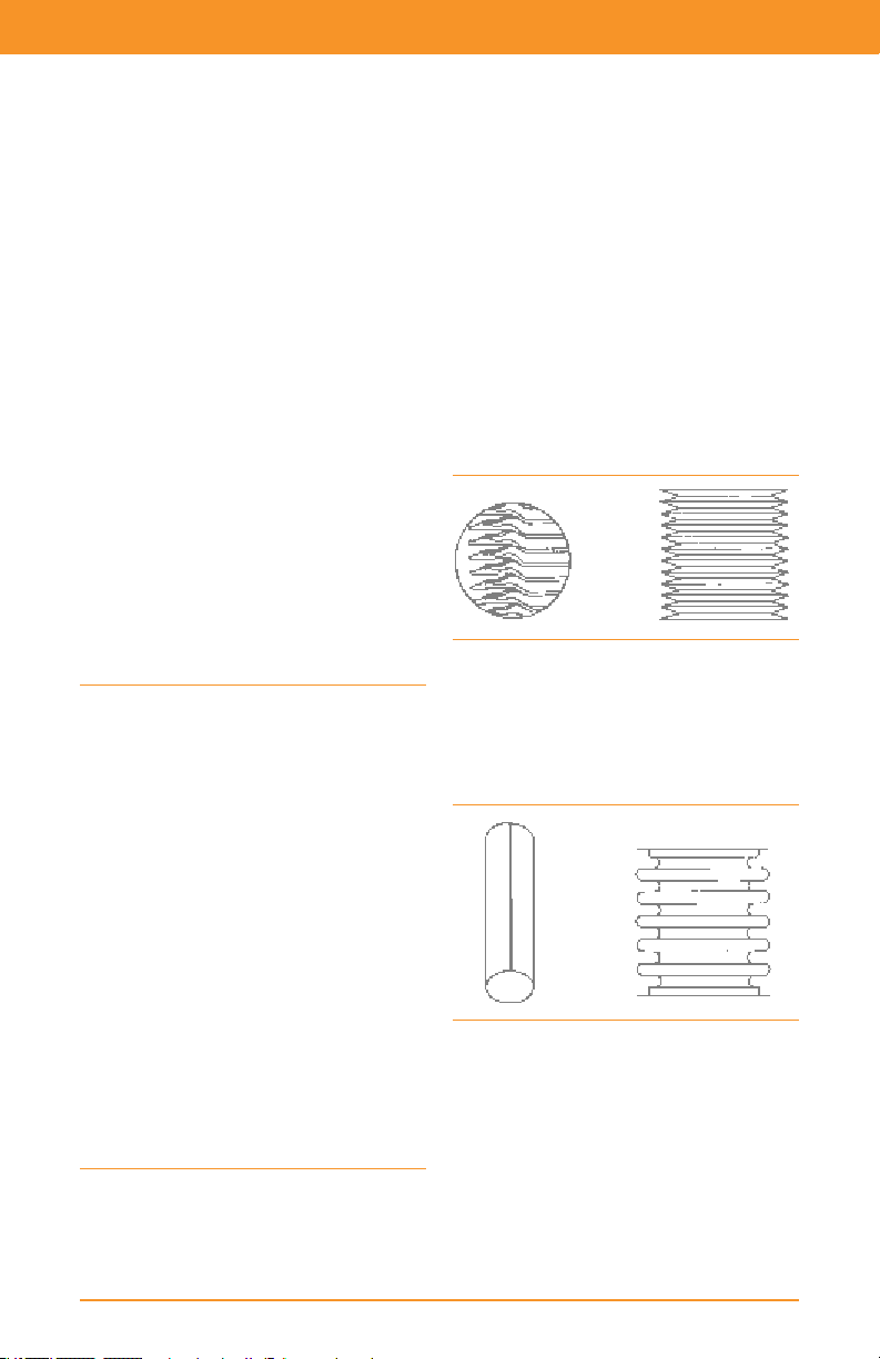
Control Valve Handbook | Chapter 3: Valve and Actuator Types
See Additional Resources »
In either case, extension wall thickness
should be minimized to cut down heat
transfer. Stainless steel is usually
preferable to carbon steel because of its
lower coefcient of thermal
conductivity. In cold service
applications, insulation can be added
around the extension to protect further
against heat inux.
3.3.2 Bellows Seal Bonnets
Bellows seal bonnets (Figure 3.17) are
used when no leakage (less than 1x10
cc/sec of helium) along the stem can be
tolerated. They are often used when the
process uid is toxic, volatile,
radioactive, or very expensive. This
special bonnet construction protects
both the stem and the valve packing
from contact with the process uid.
Standard or environmental packing box
constructions above the bellows seal
unit will prevent catastrophic failure in
case of rupture or failure of the bellows.
-6
ratings decrease with increasing
temperature. Selection of a bellows seal
design should be carefully considered
with particular attention to proper
inspection and maintenance after
installation. The bellows material should
be carefully considered to ensure the
maximum cycle life.
Two types of bellows seal designs can be
used for control valves. These are weldedleaf and mechanically-formed bellows.
The welded-leaf design (Figure 3.18) offers
a shorter total package height. Due to its
method of manufacture and inherent
design, service life may be limited.
Figure 3.18 Welded-Leaf Bellows
The mechanically-formed design (Figure
3.19) is taller by comparison and is
produced with a more repeatable
manufacturing process and, therefore,
higher reliability.
n
Figure 3.17 ENVIRO-SEAL Bellows Seal Bonnet
As with other control valve pressure and
temperature limitations, these pressure
Figure 3.19 Mechanically-Formed Bellows
3.4 Control Valve Packing
Most control valves use packing boxes
with the packing retained and adjusted
by a ange and stud bolts (shown in
Figure 3.26). Several packing materials
can be used, depending on the service
conditions expected and whether the
61
Page 62

Control Valve Handbook | Chapter 3: Valve and Actuator Types
Standard TFE V-Ring Graphite Packing Arrangements
1
2
1. Upper Wiper
2. Packing Follower
3
3. Female Adapter
4
4. V-Ring
5. Male Adapter
5
6. Washer
6
7. Spring
8. Packing Box
7
9. Lower Wiper
8
9
Figure 3.20 Packing Material Arrangements for Globe-Style Valve Bodies
2
Single Double Leak-Off
1
1
2
1. Filament Ring
1
3
1
2
1
3
1
2. Lantern Ring
3. Laminated Ring
Location of
sacrificial
zink washer,
if necessary.
application requires compliance to
environmental regulations. Brief
descriptions and service condition
guidelines for several popular materials
and typical packing material
arrangements are shown in Figure 3.20.
3.4.1 PTFE V-Ring
Plastic material with inherent ability
to minimize friction.
Molded in V-shaped rings that are
spring-loaded and self-adjusting in
the packing box. Packing lubrication
is not required.
Resistant to most known chemicals,
except molten alkali metals.
Requires extremely smooth (2 to 4
micro-inches RMS) stem nish to seal
properly. Will leak if stem or packing
surface is damaged.
Recommended temperature limits:
-40 to 232°C (-40 to 450°F)
Not suitable for nuclear service
because PTFE is easily destroyed
by radiation.
3.4.2 Laminated and Filament Graphite
Suitable for high-temperature
nuclear service or where low chloride
content is desirable (Grade GTN).
Provides leak-free operation,
high-thermal conductivity, and long
service life, but produces high stem
friction and resultant hysteresis.
Impervious to most hard-to-handle
uids and high radiation.
Suitable temperature range: cryogenic
temperatures down to -198°C (-325°F)
Lubrication is not required, but an
extension bonnet or steel yoke
should be used when packing box
temperature exceeds 427°C (800°F).
3.4.3 U.S. Regulatory Requirements for Fugitive Emissions
Fugitive emissions are non-point source
volatile organic emissions which result
from process equipment leaks.
Equipment leaks in the United States
have been estimated at over 400 million
pounds per year. Strict government
regulations, developed by the US,
dictate leak detection and repair
programs (LDAR). Valves and pumps
have been identied as key sources of
fugitive emissions. For valves, this is the
leakage to atmosphere due to packing
seal or gasket failures.
The LDAR programs require industry to
62
Page 63

Control Valve Handbook | Chapter 3: Valve and Actuator Types
< 2%, 500 ppm
> 2%, 500 ppm
> 1%, 500 ppm < 1%, 500 ppm
> 0.5%, 500 ppm < 0.5%, 500 ppm
Monthly LDAR
Quality
Improvement Plan
Quarterly LDAR
Semi-Annual LDAR
Annual LDAR
See Additional Resources »
monitor all valves (control and noncontrol) at an interval that is determined
by the percentage of valves found to be
leaking above a threshold level of 500
ppmv (some cities use a 100 ppmv
criteria). This leakage level is so slight
you cannot see or hear it. The use of
sophisticated portable monitoring
equipment is required for detection.
Detection occurs by snifng the valve
packing area for leakage using an
Environmental Protection Agency (EPA)
protocol. This is a costly and
burdensome process for industry.
The regulations do allow for the
extension of the monitoring period for
up to one year if the facility can
demonstrate a very low ongoing
percentage of leaking valves (less than
0.5% of the total valve population). The
opportunity to extend the measurement
frequency is shown in Figure 3.21.
Packing systems designed for extremely
low leakage requirements also extend
packing-seal life and performance to
support an annual monitoring objective.
The ENVIRO-SEAL packing system is one
example. Its enhanced seals incorporate
four key design principles: the
containment of the pliable seal material
through an anti-extrusion component,
proper alignment of the valve stem or
shaft within the bonnet bore, applying a
constant packing stress through Belleville
springs, and minimizing the number of
seal rings to reduce consolidation,
friction, and thermal expansion.
The traditional valve selection process
meant choosing a valve design based on
its pressure and temperature
capabilities, ow characteristics, and
material compatibility. Which valve stem
packing to use in the valve was
determined primarily by the operating
temperature in the packing box area.
The available material choices included
PTFE for temperatures below 93°C
(200°F) and graphite for highertemperature applications.
Today, choosing a valve packing system
has become much more involved due to
a number of considerations.
3.4.4 Global Standards for Fugitive Emissions
ISO 15848 is the International
Organization for Standardization’s (ISO)
standard for measurement, test, and
qualication procedures for fugitive
emissions of industrial valves. ISO
15848-1 is a classication system and
qualication for type testing of valves
that was created to enable classication
of performance of different fugitive
emission designs and to dene the type
test for evaluation and qualication of
valves where fugitive emissions
standards are specied.
Type testing means that the qualication
Figure 3.21 Measurement Frequency for Valves Controlling Volatile Organic Chemicals (VOC)
63
Page 64

Control Valve Handbook | Chapter 3: Valve and Actuator Types
test is performed on one valve and
packing system design and any
qualication is passed on to all valves
produced to that packing design. Type
testing differs from ISO 15848-2
production testing, which is a
qualication test done at the time of
assembly and can be dictated for more
than one valve assembly.
ISO 15848-1 covers both control valves
and isolation (on/off) valves. The
mechanical cycle requirements for the
two types of valves differ, as shown in
Figure 3.22. Mechanical cycles are
performed at 10% of full travel on both
sides of the 50% travel position for control
valves and full stroke for isolation valves.
Like other fugitive emission standards,
ISO 15848-1 lays out a qualication test
that includes several combinations of
leakage classes, thermal cycles, and
mechanical cycles. There are several
notable differences between ISO
15848-1 and government requirements
and standards of US origin such as LDAR
and ANSI/FCI 91-1 standard for
qualication of control valve stem seals.
ISO 15848-1 species either the vacuum
or ushing “total leakage”
measurement methods described in
Annex A of the standard.
Leakage is recorded as a leakage rate per
measured stem size. Neither of these
methods can be correlated with EPA
Method 21 (snifng method) and ISO
15848-1 states there is no correlation
intended between the tightness classes
when the test uid is helium and when
the test uid is methane. See Figures
3.23 and 3.24.
ISO 15848-1
Leakage
Tightness
Classes
AH < 10
BH < 10
CH < 10
Note: Leakage Class A is typically achieved only with
Bellows designs.
Note: Leakage classes may be denoted by “BH” or “BM”,
etc to indicate the testing uid. “H” indicates the test was
performed with Helium per a leakage rate method. “M”
indicates the test was performed with Methane using EPA
Method 21.
Measured Leak Rate (Annex A)
mg.s-1.m-1
of stem
perimeter
atm.cm3.s-1.
mm-1 of
stem diameter
-5
< 1.76x10
-4
< 1.76x10⁻⁶
-2
< 1.76x10
-7
-4
Valve
Mechanical
Typ e
Cycle Class
CC1 20,000 2
Control
Valv e
Isolation
Valv e
Figure 3.22 ISO 15848-1 Qualication Requirements
CC2 60,000 3
CC3 100,000 4
CO1 205 2
CO2 1,500 3
CO3 2,500 4
Mechanical
Cycles
Required
Tem p.
Cycles
ANSI/FCI 91-1 requires the “snifng
method” per EPA Method 21 for a “ppm”
concentration reading and cites 100ppm
and 500ppm with various cycle classes,
as shown in Figure 3.25.
64
Figure 3.23 ISO 15848-1 Measured Leak Rate
ISO 15848-1
Leakage
Tightness Classes
AM < 50ppm
BM < 100ppm
CM < 500ppm
Note: Leakage Class A is typically achieved only with
bellows designs.
Note: Leakage classes may be denoted by “BH” or “BM”,
etc to indicate the testing uid. “H” indicates the test was
performed with Helium per a leakage rate method. “M”
indicates the test was performed with Methane using
EPA Method 21.
Figure 3.24 ISO 15848-1 Measured Leak Concentration
Measured Leak Concentration
(Annex B Snifng Method per
EPA Method 21)
Today, choosing a valve packing system
has become much more involved due to
Page 65

Control Valve Handbook | Chapter 3: Valve and Actuator Types
See Additional Resources »
Class
A1 100,000 3 100 ppm
A2 100,000 3 500 ppm
B1 25,000 3 100 ppm
B2 25,000 3 500 ppm
Figure 3.25 FCI 91-1 Leakage Class Summary
a number of considerations.
For example, emissions control
Mechanical Cycles
(100% full travel)
Thermal Cycles
performance with the lowest operating
friction. See Figure 3.26.
Maximum Stem Seal Leakage
per EPA Method 21
requirements–such as those specied by
the Clean Air Act within the US and ISO
15848 on a global basis–place tighter
restrictions on sealing performance.
Constant demands for improved process
output mean that the valve packing
system must not hinder valve
performance. And today’s trend toward
extended maintenance schedules
dictates that valve packing systems
provide the required sealing over
longer periods.
Given the wide variety of valve
applications and service conditions
within industry, these variables (sealing
ability, operating friction levels,
operating life) are difcult to quantify
Figure 3.26 Single PTFE V-Ring Packing
and compare. Figures 3.31 and 3.32 use
an engineered approach in providing a
relative evaluation of packing
applicability and performance. But rst,
proper understanding of the tables
requires a clarication of trade names.
3.4.6 ENVIRO-SEAL PTFE Packing
The ENVIRO-SEAL PTFE packing system
is an advanced packing method that
utilizes a compact, live-load spring
design suited to environmental
3.4.5 Single PTFE V-Ring Packing
The single PTFE V-ring arrangement uses
a coil spring between the packing and
packing box ring. It meets the 100 ppmv
criteria for sliding-stem valves, assuming
that the pressure does not exceed 300
psi (20.7 bar) and the temperature is
between -18°C and 93°C (0°F and 200°F).
Single PTFE V-ring packing does not
come with low emissions criteria for
applications up to 750 psi and 232°C
(51.7 bar and 450°F). While it is typically
thought of as an emission-reducing
packing system, ENVIRO-SEAL PTFE
packing is also suited to nonenvironmental applications involving
high temperatures and pressures,
yielding the benet of longer, ongoing
service life in both sliding-stem and
rotary valves. See Figure 3.27.
rotary valves. It offers very good sealing
65
Page 66
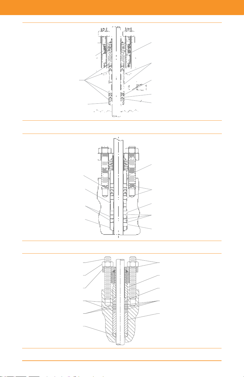
Control Valve Handbook | Chapter 3: Valve and Actuator Types
Packing
Follower
(Stainless Steel)
Lantern Rings
(Stainless Steel)
Anti-Extrusion Ring
(Filled PTFE)
Packing Ring
(PTFE)
Anti-Extrusion Ring
(Filled PTFE)
Springs
(N07718-Inconel 718)
Anti-Extrusion
Washers
Packing Box Ring
(Stainless Steel)
Anti-Seize Lubricant
Spring Pack Assembly
Guide Bushing
Packing Washer
Guide Bushing
Stud
Packing Nut
Packing Flange
Packing Ring
Packing Ring
Packing Box Ring
Figure 3.27 ENVIRO-SEAL PTFE Packing System
PTFE-Carbon/PTFE
Packing Set
Spring Pack
Assembly
Lantern Ring
Graphite
Packing Ring
Packing Ring
Figure 3.28 ENVIRO-SEAL Duplex (PTFE and Graphite) Packing System
Figure 3.29 ENVIRO-SEAL Graphite ULF Packing System
66
Bushing
Bushing
Packing
Washers
Bushing
Page 67

Control Valve Handbook | Chapter 3: Valve and Actuator Types
See Additional Resources »
3.4.7 ENVIRO-SEAL Duplex Packing
This special packing system provides the
capabilities of both PTFE and graphite
components to yield a low friction, low
emission, re-tested solution (API
Standard 589) for applications with
process temperatures up to 232°C
(450°F) in sliding-stem valves. Rotary
valves are not available with ENVIROSEAL Duplex packing. See Figure 3.28.
3.4.8 ISO-Seal PTFE Packing
This packing system is designed for
pressures exceeding the capabilities of
ENVIRO-SEAL PTFE packing for
environmental service. It is available for
use in both sliding-stem and rotary valves.
3.4.9 ENVIRO-SEAL Graphite ULF
This packing system is designed
primarily for environmental applications
at temperatures in excess of 232°C
(450°F). The patented ULF packing
system incorporates very thin PTFE
layers inside the packing rings as well as
thin PTFE washers on each side of the
packing rings. This strategic placement
of PTFE minimizes control problems,
reduces friction, promotes sealing and
extends the cycle life of the packing set.
See Figure 3.29.
3.4.10 HIGH-SEAL Graphite ULF
Identical to the ENVIRO-SEAL graphite
ULF packing system below the packingfollower, the HIGH-SEAL system utilizes
heavy-duty, large diameter Belleville
springs. These springs provide additional
follower travel and can be calibrated
with a load scale for a visual indication of
packing load and wear.
3.4.11 ISO-Seal Graphite Packing
This packing system is designed for
temperatures exceeding the capabilities
of ENVIRO-SEAL Graphite ULF packing. It
can be used from -46 to 400°C (-50 to
752°F) for environmental service. It is
available for use in both sliding-stem and
rotary valves.
3.4.12 ENVIRO-SEAL Graphite for Rotary Valves
ENVIRO-SEAL graphite packing is
designed for environmental applications
from -6 to 316°C (20 to 600°F) or for
those applications where re safety is a
concern. It can be used with pressures up
to 1500 psi (103 bar) and still satisfy the
100 ppmv EPA leakage criteria. The
packing can be used up to 371°C (700°F)
if used in non-environmental
applications. See Figure 3.30.
Figure 3.30 ENVIRO-SEAL Graphite Packing System for
Rotary Valves
3.4.13 Graphite Ribbon for Rotary Valves
Graphite ribbon packing is designed for
non-environmental applications that
span a wide temperature range, from
-198 to 538°C (-325 to 1000°F).
3.4.14 Sliding-Stem Environmental Packing Selection
Figure 3.31 provides a comparison of
various sliding-stem packing selections
and a relative ranking of seal
performance, service life, and packing
friction for environmental applications.
Braided graphite lament and double
PTFE are not acceptable environmental
sealing solutions.
67
Page 68

Control Valve Handbook | Chapter 3: Valve and Actuator Types
Packing System
Maximum Pressure & Temperature
Limits for Environmental Service
(1)
Customary U.S. Metric
Single PTFE V-Ring
ENVIRO-SEAL PTFE
ISO-Seal PTFE
ENVIRO-SEAL
Duplex
ENVIRO-SEAL
Graphite ULF
ISO-Seal Graphite
1. The values shown are only guidelines. These guidelines can be exceeded, but shortened packing life or increased leakage
might result. The temperature ratings apply to the actual packing temperature, not to the process temperature.
300 psi
0 to 200°F
750 psi
-50 to 450°F
6000 psig
-50 to -450°F
750 psi
-50 to -450°F
1500 psi
20 to 600°F
3365 psig
-50 to 752°F
20.7 bar
-18 to 93°C
1.7 bar
-46 to 232°C
414 bar
-46 to 232°C
51.7 bar
-46 to 232°C
103 bar
-7 to 315°C
232 bar
-46 to 400°C
Seal
Performance
Index
Service Life
Index
Better Long Ver y Low
Superior Very Long Low
Superior Very Long Low
Superior Very Long Low
Superior Very Long Moderate
Superior Very Long Moderate
Figure 3.31 Sliding-Stem Environmental Packing Selection
Packing System
Maximum Pressure & Temperature
Limits for Environmental Service
(1)
Customary U.S. Metric
ENVIRO-SEAL PTFE
ENVIRO-SEAL
Graphite
ISO-Seal Graphite
1. The values shown are only guidelines. These guidelines can be exceeded, but shortened packing life or increased leakage
might result. The temperature ratings apply to the actual packing temperature, not to the process temperature.
750 psi
-50 to 450°F
1500 psi
20 to 600°F
1500 psig
-50 to 752°F
103 bar
-46 to 232°C
103 bar
-18 to 315°C
103 bar
-46 to 400°C
Seal
Performance
Index
Service Life
Index
Superior Very Long Low
Superior Very Long Moderate
Superior Very Long Moderate
Packing
Friction
Packing
Friction
Figure 3.32 Rotary Environmental Packing Selection
Quick-Opening Linear Equal-Percentage
Figure 3.33 Characterized Cages for Globe-Style Valve Bodies
68
Page 69
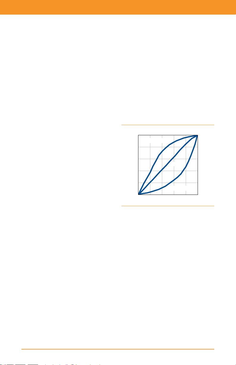
Control Valve Handbook | Chapter 3: Valve and Actuator Types
See Additional Resources »
3.4.15 Rotary Environmental Packing Selection
Figure 3.32 applies to rotary valves. In
the case of rotary valves, single PTFE and
graphite ribbon packing arrangements
do not perform well as fugitive emission
sealing solutions.
The control of valve fugitive emissions
and a reduction in industry’s cost of
regulatory compliance can be achieved
through these stem sealing technologies.
While ENVIRO-SEAL packing systems have
been designed specically for fugitive
emission applications, these technologies
also should be considered for any
application where seal performance and
seal life have been an ongoing concern or
maintenance cost issue.
n
3.5 Characterization of Cage-Guided Valve Bodies
In valve bodies with cage-guided trim, the
shape of the ow openings or windows in
the wall of the cylindrical cage determines
ow characterization. As the valve plug is
moved away from the seat ring, the cage
windows are opened to permit ow
through the valve. Standard cages have
been designed to produce linear,
equal-percentage, and quick-opening
inherent ow characteristics. Custom
characterization may also be available.
Note the differences in the shapes of the
cage windows shown in Figure 3.33. The
ow rate/travel relationship provided by
valves using these cages is either the
linear, quick-opening, or equalpercentage curves shown for contoured
valve plugs (Figure 3.34).
Cage-guided trim allows for the
inherent ow characteristic of the valve
to be easily changed by installing a
different cage. Interchange of cages to
provide a different inherent ow
characteristic does not require changing
the valve plug or seat ring. The standard
cages shown can be used with either
balanced or unbalanced trim
constructions. Soft seating, when
required, is available as a retained insert
in the seat ring and is independent of
cage or valve plug selection.
Cage interchangeability can be extended
to specialized cage designs that provide
noise attenuation or combat cavitation.
These cages typically furnish a linear
inherent ow characteristic, but require
ow to be in a specic direction through
the cage openings. Therefore, it could be
necessary to reverse the valve body in the
pipeline to obtain proper ow direction.
100
Quick-Opening
Linear
Rated Flow Coefficient (%)
0
Figure 3.34 Inherent Flow Characteristics Curves
Equal-Percentage
100
Rated Travel (%)
3.5.1 Characterized Valve Plugs
The valve plug, the movable part of a
globe-style control valve assembly,
provides a variable restriction to uid
ow. Valve plug styles are each
designed to provide a specic ow
characteristic, permit a specied
manner of guiding or alignment with
the seat ring, or have a particular
shutoff or damage-resistance capability.
The contour of the valve plug surface
next to the seat ring is instrumental in
determining the inherent ow
characteristic of a plug-characterized
control valve. As the actuator moves the
valve plug through its travel range, the
unobstructed ow area changes in size
and shape depending on the contour of
69
Page 70

Control Valve Handbook | Chapter 3: Valve and Actuator Types
the valve plug. When a constant
pressure differential is maintained across
the valve, the changing relationship
between percentage of maximum ow
capacity and percentage of total travel
range can be portrayed (Figure 3.34),
and is designated as the inherent ow
characteristic of the valve.
Commonly specied inherent ow
characteristics include linear, equalpercentage, and quick-opening. These
are described further in Chapter 5.
Stem
Seat
Ring
Port Diameter
Figure 3.35 Typical Construction to Provide
Quick-Opening Flow Characteristic
n
Valve Plug
Flow
Area
3.6 Valve Plug Guiding
Accurate guiding of the valve plug is
necessary for proper alignment with the
seat ring and efcient control of the
process uid. The common methods
used and their names are generally
self-descriptive.
Cage-Guiding: The outside diameter
of the valve plug is close to the inside
wall surface of the cylindrical cage
throughout the travel range. Since the
bonnet, cage, and seat ring are selfaligning on the assembly, correct valve
plug and seat ring alignment is assured
when the valve closes (Figure 3.15).
Top-Guiding: The valve plug is aligned
by a single guide bushing in the bonnet
or valve body, or by the packing
arrangement.
Stem-Guiding: The valve plug is
aligned with the seat ring by a guide
bushing in the bonnet that acts on the
valve plug stem.
Top- and Bottom-Guiding: The valve
plug is aligned by guide bushings in the
bonnet and bottom ange (see Figure
3.5). This is typically found in doubleported constructions.
Port-Guiding: The valve plug is aligned
by the valve body port.
n
3.7 Restricted-Capacity Control Valve Trim
Most control valve manufacturers can
provide valves with reduced- or
restricted-capacity trim parts. The
reduced ow rate might be desirable for
any of the following reasons:
Restricted capacity trim may make it
possible to select a valve body large
enough for increased future ow
requirements, but with trim capacity
properly sized for present needs.
Large bodies with restricted-capacity
trim can be used to reduce inlet and
outlet uid velocities.
Purchase of expensive pipeline
reducers can be avoided.
Over-sizing errors can be corrected by
use of restricted-capacity trim parts.
Conventional globe-style valve bodies
can be tted with seat rings with smaller
port sizes than normal and valve plugs
sized to t those smaller ports. Valves
with cage-guided trim often achieve the
reduced-capacity effect by using valve
plug, cage, and seat ring parts from a
smaller valve size of similar construction
and adapter pieces above the cage and
below the seat ring to mate those smaller
parts with the valve body (Figure 3.36).
Because reduced capacity service is not
unusual, most manufacturers provide
readily available trim part combinations
to perform the required function.
n
70
Page 71

Control Valve Handbook | Chapter 3: Valve and Actuator Types
See Additional Resources »
Figure 3.36 Adapter Method for Providing Reduced
Flow Capacity
3.8 Actuators
Pneumatically-operated control valve
actuators are the most popular type in
use, but electric, hydraulic, and manual
actuators are also widely used. The
spring-and-diaphragm pneumatic
actuator is most commonly specied
due to its dependability and simplicity of
design. Pneumatically-operated piston
actuators provide high stem force
output for demanding service
conditions. Adaptations of both
spring-and-diaphragm and pneumatic
piston actuators are available for direct
installation on rotary control valves.
3.8.1 Diaphragm Actuators
Pneumatically-operated diaphragm
actuators use air supply from
controllers, positioners, or other
sources.
Various styles include: direct-acting,
in which the increasing air pressure
pushes the diaphragm down and
extends the actuator stem (Figure
3.37); reverse-acting, in which the
increasing air pressure pushes the
diaphragm up and retracts the
actuator stem (Figure 3.37);
reversible, in which actuators can be
assembled for either direct or reverse
action (Figure 3.38); direct-acting
unit for rotary valves, in which the
increasing air pressure pushes down
on the diaphragm, which, depending
on orientation of the actuator lever
on the valve shaft, may either open
or close the valve (see Figure 3.39).
Net output thrust is the difference
between diaphragm force and
opposing spring force.
Molded diaphragms provide linear
performance and increased travels.
Output thrust required and supply
Figure 3.37 Diaphragm Actuators
Direct-Acting Reverse-Acting
71
Page 72

Control Valve Handbook | Chapter 3: Valve and Actuator Types
air pressure available dictate size.
Diaphragm actuators are simple,
dependable, and economical.
Figure 3.38 Field-Reversible Multi-Spring Actuator
Other versions for service on rotary
control valves include a sliding seal in
the lower end of the cylinder. This
permits the actuator stem to move
laterally, as well as up and down
without leakage of cylinder pressure.
This feature permits direct
connection of the actuator stem to
the actuator lever mounted on the
rotary valve shaft, thus eliminating
one joint or source of lost motion.
Figure 3.40 Control Valve with Double-Acting
Piston Actuator
Figure 3.39 Diaphragm Actuator for Rotary Valve
3.8.2 Piston Actuators
Piston actuators are pneumaticallyoperated using high-pressure plant
air up to 150 psig (10.3 bar), often
eliminating the need for a supply
pressure regulator.
Piston actuators furnish maximum
thrust output and fast stroking speeds.
Piston actuators are double-acting to
give maximum force in both
directions, or spring-return to
provide fail-open or fail-closed
operation (Figure 3.40).
Various accessories can be
incorporated to position a doubleacting piston in the event of supply
pressure failure, including pneumatic
trip valves and lock-up systems.
72
Figure 3.41 Control Valve with Scotch-Yoke
Piston Actuator
3.8.3 Manual Actuators
Manual actuators are useful where
automatic control is not required,
but where ease of operation and
good manual control is still necessary
(Figures 3.42 and 3.43). They are
often used to actuate the bypass
valve in a three-valve bypass loop
around control valves for manual
control of the process during
maintenance or shut down of the
automatic system.
Manual actuators are available in
various sizes for both globe-style and
rotary valves.
Page 73

Control Valve Handbook | Chapter 3: Valve and Actuator Types
See Additional Resources »
Dial-indicating devices are available
for some models to permit accurate
repositioning of the valve plug or disk.
Manual actuators are much less
expensive than automatic actuators.
Figure 3.42 Manual Actuator for Sliding-Stem Valves
3.8.5 Electric Actuators
Electric actuator designs use an electric
motor and some form of gear reduction
to move the valve plug (Figures 3.45 and
3.46). While electric actuators have
traditionally been limited to on/off
operation, some are now capable of
continuous control. The use of brushless
motors in electric actuators can reduce
or eliminate motor burnout associated
with turning the motor on and off rapidly.
The initial purchase price still tends to
remain above that of pneumatic
actuation. The primary usage of electric
actuation is in areas where instrument air
is not readily available or where an
insufcient quantity of valves exist to
justify the cost of a compressor system.
n
Figure 3.43 Manual Actuator for Rotary Valves
3.8.4 Rack-and-Pinion Actuators
Rack-and-pinion designs provide a
compact and economical solution for
rotary valves (Figure 3.44). Because of
backlash, they are typically used for on/
off applications or where process
variability is not a concern.
Figure 3.44 Rack-and-Pinion Actuator
Figure 3.45 Electric Actuator for Sliding-Stem Valve
Figure 3.46 Electric Actuator for Rotary Valve
73
Page 74

Chapter 4
Control Valve Accessories
Page 75

Control Valve Handbook | Chapter 4: Control Valve Accessories
See Additional Resources »
Today, modern control systems use
electronic signaling to command the
control valve to open, close, or throttle.
Additionally, these systems use position
feedback signals and diagnostic
information to validate the operation
of the control valve. Furthermore, the
performance expectations of control
valves in terms of speed of response,
accuracy, stability, reliability, and safety
vary based on the process control needs.
Because control valves are installed in
many different and unique applications,
control valve accessories are necessary.
Accessories are the broad category of
instruments that are directly connected
to a control valve assembly.
There are ve basic reasons that
instrumentation and accessories are
added to a control valve:
Improve process control
Improve safety for the process or
personnel
Improve valve performance or speed
of response
Monitor or verify the valve
responsiveness
Diagnose potential valve issues
4.1 Environmental & Application Considerations
Industrial plants, factories, mines, and
mills experience tough environmental
conditions due to their geographical
location and the processes involved
in manufacturing their products. As a
result, valves and instruments in these
facilities must be rugged and reliable.
Ambient temperatures for
instrumentation can range from -60
to 125°C (-76 to 257°F). Corrosive
atmospheres, such as salt water and
chemical exposure, may require
stainless steel or engineered resin
materials of construction. Intense
vibration may require sturdy instrument
mounting, rugged internal mechanisms,
or remote mounting capability.
High levels of humidity can lead to
corrosion, so protection of electronic
components may be necessary.
Hazardous locations containing gaseous
or dusty atmospheres may require
instrumentation that is designed using
protection concepts, such as ameproof,
explosion proof, intrinsic safety, or
non-incendive. These environmental
and application conditions should be
considered when selecting the proper
control valve accessories.
4.2 Positioners
A common control valve accessory is
the valve position controller, also called
a positioner. The fundamental function
of a positioner is to deliver pressurized
air to the valve actuator, such that
the position of the valve stem or shaft
corresponds to the set point from the
control system. Positioners are typically
used when a valve requires throttling
action. A positioner requires position
feedback from the valve stem or shaft
and delivers pneumatic pressure to the
actuator to open and close the valve.
The positioner must be mounted on or
near the control valve assembly. There
are three main categories of positioners,
depending on the type of control signal,
the diagnostic capability, and the
communication protocol.
4.2.1 Pneumatic Positioners
The rst category of positioners
are pneumatic positioners. Legacy
processing units may use pneumatic
pressure signaling as the control set
point to the control valves. Pressure is
typically modulated between 20.7 to
103 kPa (3 to 15 psig) to move the valve
from 0 to 100% position.
In a common pneumatic positioner
75
Page 76
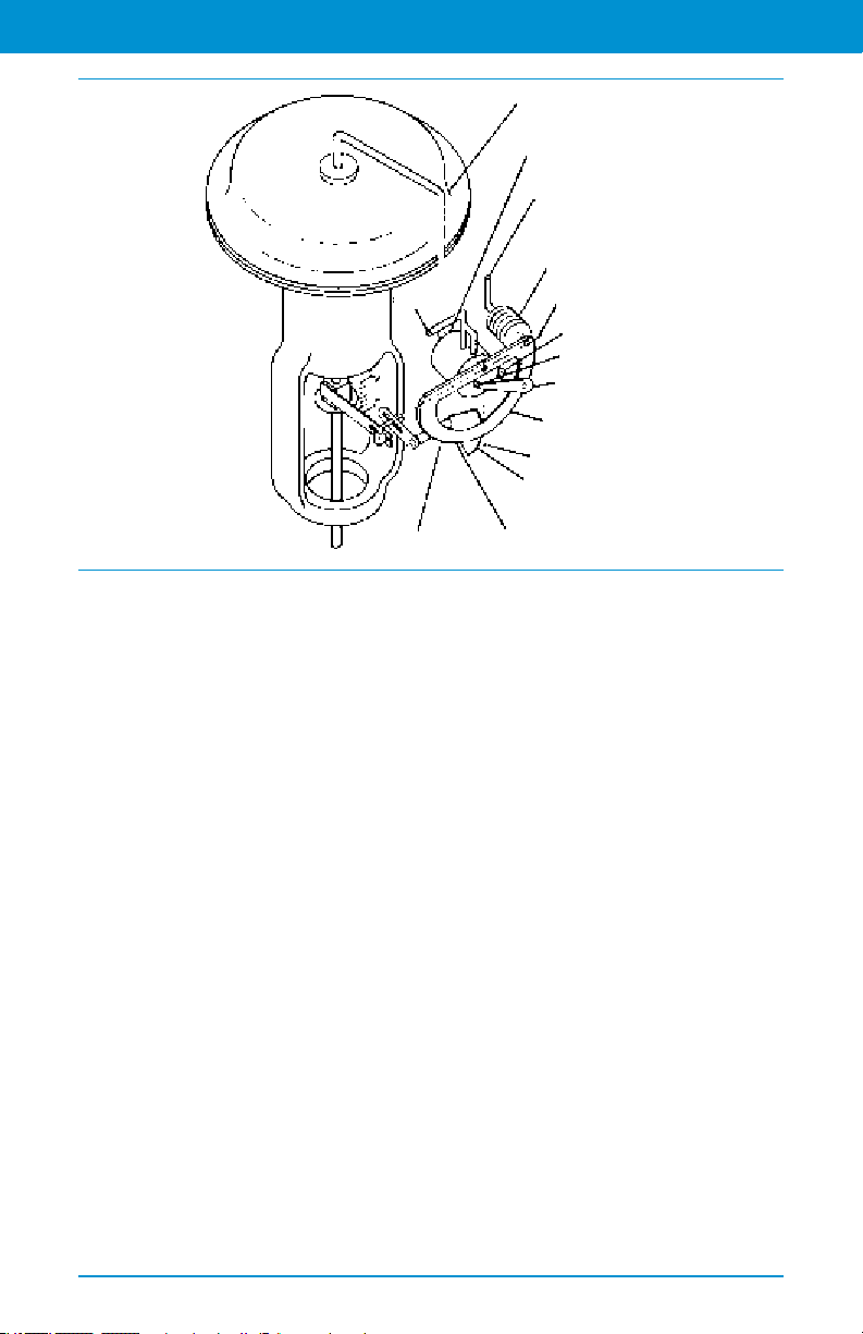
Control Valve Handbook | Chapter 4: Control Valve Accessories
Supply
Output to
Diaphragm
Relay
Instrument
Bellows
Feedback Axis
Nozzle
Flapper Assembly
Direct Action
Quadrant
Input Axis
Cam
Pivot
Beam
Figure 4.1 Typical Pneumatic, Single-Acting Positioner Design
design (Figure 4.1), the position of the
valve stem or shaft is compared with the
position of a bellows that receives the
pneumatic control signal. When the
input signal increases, the bellows
expands and moves a beam. The beam
pivots about an input axis, which moves
a apper closer to the nozzle. The nozzle
pressure increases, which increases the
output pressure to the actuator through
a pneumatic amplier relay. The
increased output pressure to the
actuator causes the valve stem to move.
Stem movement is fed back to the beam
by means of a cam. As the cam rotates,
the beam pivots about the feedback axis
to move the apper slightly away from
the nozzle. The nozzle pressure
decreases and reduces the output
pressure to the actuator. Stem
movement continues, backing the
apper away from the nozzle until
equilibrium is reached.
When the input signal decreases, the
bellows contracts (aided by an internal
range spring) and the beam pivots
Reverse Action
Quadrant
about the input axis to move the apper
away from the nozzle. Nozzle pressure
decreases and the relay permits the
release of diaphragm casing pressure
to the atmosphere, which allows the
actuator stem to move upward. Through
the cam, stem movement is fed back
to the beam to reposition the apper
closer to the nozzle. When equilibrium
conditions are obtained, stem movement
stops and the apper is positioned to
prevent any further decrease in actuator
pressure. See Figure 4.1.
4.2.2 Analog I/P Positioners
The second type of positioner is an
analog I/P positioner. Most modern
processing units use a 4 to 20 mA DC
signal to modulate the control valves.
This introduces electronics into the
positioner design and requires that the
positioner convert the electronic current
signal into a pneumatic pressure signal
(current-to-pneumatic or I/P).
In a typical analog I/P positioner (see
Figure 4.2), the converter receives a DC
76
Page 77

Control Valve Handbook | Chapter 4: Control Valve Accessories
Converter
Supply
Output to
Actuator
Relay
Rotary
Shaft Arm
Flapper Assembly
Quadrant
Pneumatic Signal
See Additional Resources »
input signal and provides a proportional
pneumatic output signal through
a nozzle/apper arrangement. The
pneumatic output signal provides the
input signal to the pneumatic positioner.
Otherwise, the design is the same as the
pneumatic positioner.
-
+
4-20 mA
Input Signal
from Converter
Bellows
Feedback Axis
Nozzle
Beam
Direct-Acting
Quadrant
Input Axis
Pivot
Figure 4.2 Typical Single-Acting Analog I/P
Positioner Design
Reverse-Acting
Cam
4.2.3 Digital Valve Controllers
While pneumatic positioners and analog
I/P positioners provide basic valve
position control, digital valve controllers
add another dimension to positioner
capabilities. This type of positioner is a
microprocessor-based instrument. The
microprocessor enables diagnostics and
two-way communication to simplify
setup and troubleshooting.
In a typical digital valve controller,
the control signal is read by the
microprocessor, processed by a digital
algorithm, and converted into a drive
current signal to the I/P converter.
The microprocessor performs the
position control algorithm rather
than a mechanical beam, cam, and
apper assembly. As the control signal
increases, the drive signal to the I/P
converter increases, increasing the
output pressure from the I/P converter.
This pressure is routed to a pneumatic
amplier relay and provides two
output pressures to the actuator. With
increasing control signal, one output
pressure always increases and the other
output pressure decreases.
Figure 4.3 Digital Valve Controller Mounted on a
Control Valve
Double-acting actuators use both
outputs, whereas single-acting actuators
use only one output. The changing
output pressure causes the actuator
stem or shaft to move. Valve position
is fed back to the microprocessor.
The stem continues to move until the
correct position is attained. At this
point, the microprocessor stabilizes the
drive signal to the I/P converter until
equilibrium is obtained.
In addition to the function of controlling
the position of the valve, a digital
valve controller has two additional
capabilities: diagnostics and two-way
digital communication.
4.2.3.1 Diagnostics
The microprocessor inside the digital
valve controller allows the positioner to
run, analyze, and store diagnostic tests.
Diagnostic information is useful in
determining the health of the entire
control valve assembly. Through the
77
Page 78

Control Valve Handbook | Chapter 4: Control Valve Accessories
use of pressure sensors, temperature
sensors, travel sensors, and internal
readings, graphical representations of
control valve performance and health are
created and recommended actions are
presented. This information is then used
to identify elements of the control valve
assembly that may require maintenance.
4.2.3.2 Two-Way Digital Communication
The microprocessor inside the digital
valve controller also allows the
positioner to communicate with the
control system via a digital signal. This
enables the digital valve controller to
provide additional feedback, such as
actual valve travel and diagnostic alerts
back to the control system.
One widely used protocol is HART
®
communication. HART communication
uses a digital signal superimposed over
the traditional 4 to 20 mA DC control
signal. This communication protocol
allows the host system to be used
to congure, calibrate, and monitor
the health of the positioner. HART
communication offers the benets
of digital communication with the
familiarity of a 4 to 20 mA control system.
FOUNDATION
™
eldbus is another
industry standard protocol. This protocol
is all digital, which means that the
control signal (set point) is digital, rather
than a 4 to 20 mA DC current. Similar to
HART communication, the host system
can also be used to congure, calibrate,
and monitor the positioner.
PROFIBUS is also a common industry
protocol that provides all digital
communication. The physical layer
for PROFIBUS and FOUNDATION
eldbus is the same; however, the
communication protocols differ and
offer their own advantages.
Wireless technology offers an
additional method to communicate
information between the control
system and the digital valve controller.
For positioners outtted with wireless
capability, digital information can be
transmitted independent of the control
system wiring.
4.3 I/P Transducers
In some applications, the high level of
postioning accuracy that a positioner
provides is not required. In these
applications, an electro-pneumatic (I/P)
transducer can be used. An I/P transducer
(Figure 4.4) uses a converter module that
converts a 4 to 20 mA current input to a
proportional pressure output. An internal
pneumatic amplier relay provides the
capacity necessary to deliver output
pressure to the control valve actuator.
There is no valve position feedback and
responsiveness is very quick.
Figure 4.4 Transducer Mounted on a Control Valve
4.4 Volume Boosters
Positioners and I/P transducers are
designed to provide enough pneumatic
output capacity to drive a typical
throttling control valve. However, some
78
Page 79

Control Valve Handbook | Chapter 4: Control Valve Accessories
See Additional Resources »
applications require faster stroking
speeds. When the actuator volume is
large, the positioning speed of response
can become more of a concern.
Volume boosters are used to provide
additional pneumatic output capacity
to a valve assembly (Figure 4.5). A
large, sudden change in input signal
(output pressure from the positioner)
causes a pressure differential to exist
Diaphragms
Exhaust
Exhaust Port
Supply
between the input signal and the
output of the booster. When this
occurs, the diaphragms move to open
the supply port or the exhaust port,
whichever action is required to reduce
the differential. The port remains open
until the difference between the booster
input and output pressure is within the
deadband limit of the booster.
With the bypass restriction adjusted
Signal Input
Bypass Restriction
Adjusting Screw
Bypass Restriction
Supply Port
Output to Actuator
Figure 4.5 Volume Booster Sectional View
Figure 4.6 Typical Booster Installation with a Single-Acting Actuator
Pipe Tee
Pipe Bushing
Body
Body
Protector
Optional
Diagnostic
Connection
Volume
Booster
Pipe Nipple
Positioner
Actuator
Pressure
Regulator
Positioner
Output
Signal
Supply
79
Page 80

Control Valve Handbook | Chapter 4: Control Valve Accessories
for stable operation, signals having
small magnitude and rate changes
pass through the bypass restriction
and into the actuator without initiating
booster operation. Both the supply and
exhaust ports remain closed, preventing
unnecessary air consumption and
possible saturation of positioner relays.
Single-acting actuators typically use
one volume booster (Figure 4.6).
Double-acting actuators require at
least two volume boosters, one to feed
each side of the actuator piston. Some
applications, such as compressor antisurge or turbine bypass, may require
additional volume boosters to provide
the needed pneumatic volume for fast
valve response.
4.5 Safety Instrumented Systems (SIS)
The primary purpose of a control valve
is to modulate the ow of liquid or
gas in a pipe within a process control
loop. Within these same process loops,
there are also emergency vent, block,
or isolation valves. These valves are
typically on/off valves that are used
to take the process loop to a safe
state in the event of a process control
emergency (Figure 4.7). A separate
safety system, often controlled by a
logic solver, controls these valves.
4.5.1 Partial Stroke Testing
Because safety valves are static and do
not modulate under normal conditions,
they are prone to sticking. When an
emergency demand occurs, there is a
risk that the valves will not move when
commanded. To mitigate this risk, the
digital valve controller can be used as a
partial stroke testing device.
An important function of the instrument
is periodically exercising the valve. This is
performed with a valve partial stroke test
(PST). The PST slowly moves the valve
a portion of the total valve travel and
then returns to the normal state. This
exercises the mechanical components of
the safety valve with minimal disruption
to the process loop. Furthermore,
the digital valve controller has the
ability to diagnose potential issues and
communicate any alerts if the test fails.
Figure 4.7 SIS Digital Valve Controller on a Safety Valve
80
Page 81

Control Valve Handbook | Chapter 4: Control Valve Accessories
See Additional Resources »
4.5.2 Safety Function and
Product Certication
A spring-return, single-acting actuator
provides an inherent fail mode for the
valve assembly. During an emergency
demand, the typical method to move the
valve to the safe state is to remove the
air pressure to the actuator and allow the
spring to position the valve. A solenoid
valve and/or digital valve controller can
be used to perform this function. There
may be additional instrumentation
on the safety valve, such as boosters,
position transmitters, and trip systems.
All of these elements must be evaluated
for their effect on the safety system.
These elements can fail by causing
an unplanned trip or by not getting
the safety valve to the safe state. The
Failure Modes, Effects, and Diagnostics
Analysis (FMEDA) provides metrics
for each component. This allows a
safety engineer to design the safety
instrumented system to the desired
level of risk reduction. See Chapter
12 for more information about safety
instrumented systems.
4.6 Controllers
In some applications, control of the
process is performed locally without
the need for a large scale distributed
control system (DCS) or programmable
logic controller (PLC). Local controllers
are used to measure process conditions,
such as pressure, temperature, or level
and directly drive the pneumatic output
pressure to a control valve (Figure 4.8).
The input to the local controller is
typically pressure, differential pressure,
temperature, or level displacement.
The process measurement is translated
into a beam-apper assembly
movement, which is connected to an
input element. The input element can
be a Bourdon tube, bellows assembly,
liquid displacement lever assembly, or
temperature bulb.
Figure 4.8 Pneumatic Controller on a Control Valve
The input element is connected to the
process pointer (set point adjustment)
and to the apper by connecting links.
As the process input increases (in a
direct-acting controller), the apper
moves toward the nozzle, which restricts
ow through the nozzle and increases
nozzle pressure. When this occurs, relay
action increases the output pressure to
the actuator, which modulates the
control valve. Output pressure is fed
back to the proportional bellows. The
action of the proportional bellows
counters the apper movement that
resulted from the process input change.
It then moves the apper away from the
nozzle until the controller reaches a
point of equilibrium. The set point
adjustment changes the proximity of the
nozzle and apper, as does a change in
process input. However, when the set
point is changed, the nozzle moves with
respect to the apper.
81
Page 82

Control Valve Handbook | Chapter 4: Control Valve Accessories
Proportional-Only Control
The proportional band adjustment
knob positions the nozzle on the apper.
Increasing or widening the proportional
band moves the nozzle to a position on
the apper where less apper motion
occurs, decreasing the gain of the
controller. Decreasing or narrowing the
proportional band moves the nozzle
toward a position where more apper
motion occurs, increasing the gain.
Controller action is changed from direct
to reverse by turning the proportional
band adjustment knob to position the
nozzle to a point on the apper where
the direction of the apper motion
versus the input motion is reversed.
With the controller in the reverse-acting
mode, an increase in process input
causes a decrease in output pressure
to the actuator. Supply pressure bleeds
through a xed orice in the relay and
exits through the nozzle. The nozzle
pressure registers on the large relay
diaphragm and modulates loading
pressure on the small relay diaphragm.
This also modulates the controller output
pressure to the actuator (Figure 4.9).
Controllers with proportional-plusreset operation are similar to that of
proportional-only controllers, except that
output pressure is fed back to the reset
and proportional bellows. In operation,
proportional-plus-reset controllers
minimize the offset between the process
variable and the set point.
Controllers with proportional-plus-resetplus-rate have a rate valve, an adjustable
restriction that briey maintains
the controller gain to accelerate the
corrective action for slow systems
(Figure 4.10). The rate action delays the
gain reduction just long enough to allow
the system to respond to the change,
but not long enough for the system to
become unstable. Then, the low gain
provided by the proportional action
keeps the system stable. Finally, the reset
action slowly increases the gain and
returns the process toward the set point.
Anti-reset windup reduces overshoot
of the process input that can result
from large or prolonged deviation
from the set point. This option can be
adjusted to operate on either increasing
or decreasing output pressure. The
differential relief valve operates when the
difference between proportional bellows
pressure and reset bellows pressure
reaches a predetermined value.
Manual Set Point
Adjustment
Process Pointer
Remote Set Point
Connected Here
Input Element
Connected Here
Connecting
Link
Supply Pressure
Output Pressure
Nozzle Pressure
Reset Pressure
Proportional Pressure
Figure 4.9 Pneumatic Controller Schematic
Beam
Proportional
Bellows
Flapper
Nozzle
82
Reset Bellows (Vented)
Proportional
Band Adjustment
Feedback
Link
Feedback
Motion
Direct-Action
Quadrant
Supply Pressure
Reverse-Action Quadrant
Flapper
Pivot
Input
Motion
Output Pressure
to Final Control Element
Relay
Page 83
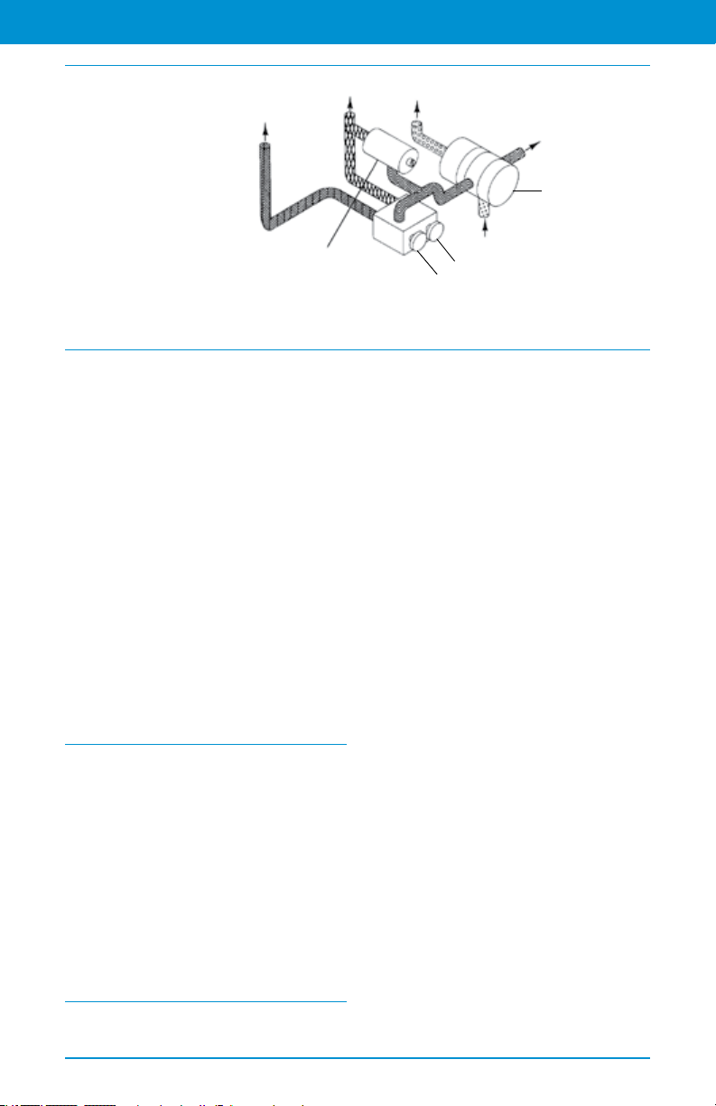
To Proporitional
See Additional Resources »
Bellows
Control Valve Handbook | Chapter 4: Control Valve Accessories
To Reset
Bellows
To Nozzle
Output
Relay
Supply Pressure
Output Pressure
Nozzle Pressure
Reset Pressure
Proportional Pressure
Figure 4.10 Pneumatic Controller Schematic
Differential
Relief Valve
4.7 Position Transmitters
The purpose of a position transmitter is
to provide independent valve position
feedback to the control system.
Position feedback is often used for
process monitoring, troubleshooting,
or startup/shutdown verication.
The position transmitter is mounted
directly to the valve and measures the
position of the valve stem or shaft.
In a wired installation, the position
transmitter provides a 4 to 20 mA signal
that corresponds with the throttling
range of the control valve. In a wireless
installation, the position transmitter
provides a 0 to 100% digital signal
(Figure 4.11).
Supply Pressure
Reset Valve
Rate Valve
Proportional + Reset + Rate Control
With Anti-Reset Windup
4.8 Limit Switches
The purpose of a limit switch is to
provide a discrete open or close signal
to the control system when the valve
reaches a specic position within its
range of travel. Limit switches are
also used for process monitoring,
troubleshooting, or startup/shutdown
verication. The limit switch receives
position feedback from the valve stem
or shaft and will send either a wired
or a wireless signal to the control
system. There are many different
switch technologies available, such as
proximity, solid state, magnetic, and
contact closure.
Figure 4.11 Wireless Position Monitor Mounted on
an Actuator
4.9 Solenoid Valves
A solenoid valve is installed in the
pneumatic tubing path to the actuator.
In some applications, the solenoid valve
will vent the air from the actuator to
allow the valve to move to its no air, fail
state. In other applications, the solenoid
valve will trap air in the actuator to
lock the valve in its current position.
Three-way solenoids are generally used
to operate spring-return actuators and
four-way solenoids are generally used for
double-acting actuators. The solenoid
valve is activated by making or breaking
83
Page 84

Control Valve Handbook | Chapter 4: Control Valve Accessories
a discrete electrical signal from the
control system. See Chapter 11 for more
information about solenoid valves.
4.10 Trip Systems
Trip systems are used in control
applications where a specic actuator
action is required in the event that supply
pressure is lost (Figure 4.12). These
are used with double-acting actuators
that do not have an inherent no air, fail
state or with single- or double-acting
actuators to provide pneumatic lock-up.
When supply pressure falls below the trip
point, the trip valve causes the actuator
to fail up, lock in the last position, or fail
down. For double-acting applications,
a volume tank provides the reserve
pneumatic air capacity to operate
the valve until the supply pressure is
restored. When the supply pressure
rises above the trip point, the trip valve
automatically resets, allowing the
system to return to normal operation.
4.11 Handwheels
Handwheels for diaphragm actuators
are often used as adjustable travel
stops. They also provide a ready means
of positioning the control valve in an
emergency.
Side-mounted handwheels can be used
to stroke the valve in either direction
at any point in the actuator stem
travel (Figure 4.13). The side-mounted
handwheel can be positioned to limit
travel in either direction, but not both
at the same time. With the handwheel
in the neutral position, automatic
operation is possible throughout full
valve travel. In any other position, valve
travel will be restricted.
Top-mounted handwheels are used for
infrequent service to manually stroke
the valve (Figure 4.14).
Spring
Valve Plug
Upper Diaphragm
Exhaust Port
Supply Pressure
Lower Diaphragm
Figure 4.12 Trip Valve Shown in Tripped Condition
Port D
Port E
Lower
Ports
Supply Pressure
Control Pressure to Top of
Cylinder (Blocked)
Control Pressure to Bottom
of Cylinder (Blocked)
Port F
Main
Spring
84
Actuator
Vent
Port A
Port B
Upper Ports
Plug
AssembliesPort C
Pressure to Top of Cylinder
(from Volume Tank)
Pressure from Bottom of Cylinder
(Venting)
Lower Diaphragm Loading Pressure
(Being Vented)
Volume
Tank
Control
Device
Page 85

Control Valve Handbook | Chapter 4: Control Valve Accessories
See Additional Resources »
Figure 4.13 Actuator with Side-Mounted Handwheel
Figure 4.14 Actuator with Top-Mounted Handwheel
85
Page 86

Chapter 5
Control Valve Sizing
Page 87

Control Valve Handbook | Chapter 5: Control Valve Sizing
See Additional Resources »
Control valves handle all kinds of uids at
temperatures from the cryogenic range
to well over 538°C (1000°F). Selection of
a control valve body assembly requires
particular consideration to provide the
best available combination of valve body
style, material, and trim construction
design for the intended service. Capacity
requirements and system operating
pressure ranges also must be considered
in selecting a control valve to ensure
satisfactory operation without undue
initial expense.
Reputable control valve manufacturers
and their representatives are dedicated
to helping select the control valve most
appropriate for the existing service
conditions. Because there are frequently
several possible correct choices for an
application, it is important that all the
following information be provided for
any set of conditions deemed important:
Type of uid to be controlled
Temperature of uid
Viscosity of uid
Concentrations of all constituents
including trace impurities
Process conditions during startup,
normal operations, and shutdowns
Chemical cleaning that may occur
periodically
Specic gravity or density of uid
Fluid ow rate
Inlet pressure at valve
Outlet pressure or pressure drop
Pressure drop at shutoff
Maximum permissible noise level,
if pertinent, and the measurement
reference point
Degrees of superheat or existence of
ashing, if known
Inlet and outlet pipeline size and
schedule
Special tagging information required
Cast body material (ASTM A216
grade WCC, ASTM A217 grade WC9,
ASTM A351 CF8M, etc.)
End connections and valve rating
(screwed, Class 600 RF anged, Class
1500 RTJ anges, etc.)
Action desired on air failure (valve to
open, close, or retain last controlled
position)
Instrument air supply available
Instrument signal (3 to 15 psig,
4 to 20 mA, HART, etc.)
In addition, the following information
will require the agreement of the user
and the manufacturer depending on the
purchasing and engineering practices
being followed.
Valve type number
Valve size
Valve body construction (angle,
double-port, buttery, etc.)
Valve plug guiding (cage-style, portguided, etc.)
Valve plug action (push-down-toclose or push-down-to-open)
Port size (full or restricted)
Valve trim materials required
Flow action (ow tends to open valve
or ow tends to close valve)
Actuator size required
Bonnet style (plain, extension,
bellows seal, etc.)
Packing material (PTFE V-ring,
laminated graphite, environmental
sealing systems, etc.)
Accessories required (positioner,
handwheel, etc.)
Some of these options have been
discussed in previous chapters of this
book, and others will be explored in this
and following chapters.
87
Page 88

Control Valve Handbook | Chapter 5: Control Valve Sizing
Valve Selection Process
1. Determine Service Conditions
P1, ∆P, Q, T1, uid properties, allowable noise, etc.
Select appropriate ANSI pressure class required for valve body and trim.
2. Calculate Preliminary Cv Required
Check noise and cavitation levels.
3. Select Trim Type
If no noise or cavitation indication, choose standard trim.
If aerodynamic noise is high, choose a noise reduction trim.
If liquid noise is high and/or cavitation is indicated, choose a cavitation reduction trim.
4. Select Valve Body and Trim Type
Select valve body and trim size with required C
Note travel, trim group, and shutoff options.
5. Select Trim Materials
Select trim materials for your application.
Make sure trim selected is available in the trim group for the valve size selected.
6. Consider Options
Consider options on shutoff, stem packing, etc.
.
v
5.1 Control Valve Dimensions
5.1.1 Face-to-Face Dimensions for Flanged, Globe-Style Control Valves
Classes 125, 150, 250, 300, and 600 (Dimensions in Accordance with ANSI/ISA-75.08.01)
Pressure Ratings and End Connections
Valve Size
DN NPS mm in mm in mm in
15 1/2 184 7.25 197 7.75 190 7.50
20 3/4 184 7.25 197 7.75 194 7.62
25 1 184 7.25 197 7.75 197 7.75
40 1-1/2 222 8.75 235 9.25 235 9.25
50 2 254 10.00 267 10.50 267 10.50
65 2-1/2 276 10.88 289 11.38 292 11.50
80 3 298 11.75 311 12.25 318 12.50
100 4 352 13.88 365 14.38 368 14.50
150 6 451 17.75 464 18.25 473 18.62
200 8 543 21.38 556 21.88 568 22.38
250 10 673 26.50 686 27.00 708 27.88
300 12 737 29.00 749 29.50 775 30.50
350 14 889 35.00 902 35.50 927 36.50
400 16 1016 40.00 1029 40.50 1057 41.62
Abbreviations used above: FF - Flat Face; RF - Raised Face; RTJ - Ring-Type Joint; CI - Cast Iron
88
Class 125 FF (CI)
Class 150 RF (STL)
Class 150 RTJ (STL)
Class 250 RF (CI)
Class 300 RF (STL)
Page 89

Control Valve Handbook | Chapter 5: Control Valve Sizing
See Additional Resources »
Face-to-Face Dimensions for Flanged, Globe-Style Valves continued...
Valve Size
DN NPS mm in mm in mm in
15 1/2 202 7.94 203 8.00 203 8.00
20 3/4 206 8.12 206 8.12 206 8.12
25 1 210 8.25 210 8.25 210 8.25
40 1-1/2 248 9.75 251 9.88 251 9.88
50 2 282 11.12 286 11.25 284 11.37
65 2-1/2 308 12.12 311 12.25 314 12.37
80 3 333 13.12 337 13.25 340 13.37
100 4 384 15.12 394 15.50 397 15.62
150 6 489 19.24 508 20.00 511 20.12
200 8 584 23.00 610 24.00 613 24.12
250 10 724 28.50 752 29.62 755 29.74
300 12 790 31.12 819 32.25 822 32.37
350 14 943 37.12 972 38.25 475 38.37
400 16 1073 42.24 1108 43.62 1111 43.74
Abbreviations used above: STL - Steel
Class 300 RTJ (STL) Class 600 RF (STL) Class 600 RTJ (STL)
Pressure Ratings and End Connections
Classes 900, 1500, and 2500 (Dimensions in Accordance with ANSI/ISA-75.08.06)
Valve Size
DN NPS Short Long Short Long Short Long
15 1/2 273 292 10.75 11.50 273 292
20 3/4 273 292 10.75 11.50 273 292
25 1 273 292 10.75 11.50 273 292
40 1-1/2 311 333 12.25 13.12 311 333
50 2 340 375 13.38 14.75 340 375
65 2-1/2 - - - 410 - - - 16.12 - - - 410
80 3 387 441 15.25 17.38 406 460
100 4 464 511 18.25 20.12 483 530
150 6 600 714 21.87 28.12 692 768
200 8 781 914 30.75 36.00 838 972
250 10 864 991 34.00 39.00 991 1067
300 12 1016 1130 40.00 44.50 1130 1219
350 14 - - - 1257 - - - 49.50 - - - 1257
400 16 - - - 1422 - - - 56.00 - - - 1422
450 18 - - - 1727 - - - 68.00 - - - 1727
mm in mm
Class 900 Class 1500
89
Page 90

Control Valve Handbook | Chapter 5: Control Valve Sizing
Face-to-Face Dimensions for Flanged, Globe-Style Valves continued...
Valve Size
DN NPS Short Long Short Long Shor t Long
15 1/2 10.75 11.50 308 318 12.12 12.50
20 3/4 10.75 11.50 308 318 12.12 12.50
25 1 10.75 11.50 308 318 12.12 12.50
40 1-1/2 12.25 13.12 359 381 14.12 15.00
50 2 13.38 14.75 - - - 400 - - - 16.25
65 2-1/2 - - - 16.12 - - - 441 - - - 17.38
80 3 16.00 18.12 498 660 19.62 26.00
100 4 19.00 20.87 575 737 22.62 29.00
150 6 24.00 30.25 819 864 32.25 34.00
200 8 33.00 38.25 - - - 1022 - - - 40.25
250 10 39.00 42.00 1270 1372 50.00 54.00
300 12 44.50 48.00 1321 1575 52.00 62.00
350 14 - - - 49.50 - - - - - - - - - - - 400 16 - - - 56.00 - - - - - - - - - - - 450 18 - - - 68.00 - - - - - - - - - - - -
Class 1500 Class 2500
in mm in
5.1.2 Face-to-Face Dimensions for Butt Weld-End, Globe-Style Valves
Classes 150, 300, 600, 900, 1500, and 2500 (Dimensions in Accordance with ANSI/
ISA-75.08.05)
Valve Size
DN NPS Short Long Short Long Short Long
15 1/2 187 203 7.38 8.00 194 279
20 3/4 187 206 7.38 8.25 194 279
25 1 187 210 7.38 8.25 197 279
40 1-1/2 222 251 8.75 9.88 235 330
50 2 254 286 10.00 11.25 292 375
65 2-1/2 292 311 11.50 12.25 292 375
80 3 318 337 12.50 13.25 318 460
100 4 368 394 14.50 15.50 368 530
150 6 451 508 17.75 20.00 508 768
200 8 543 610 21.38 24.00 610 832
250 10 673 752 26.50 29.62 762 991
300 12 737 819 29.00 32.35 914 1130
350 14 851 1029 33.50 40.50 - - - 1257
400 16 1016 1108 40.00 43.62 - - - 1422
450 18 1143 - - - 45.00 - - - - - - 1727
Class 150, 300, and 600 Class 900 and 1500
mm in mm
90
Page 91

Control Valve Handbook | Chapter 5: Control Valve Sizing
See Additional Resources »
Face-to-Face Dimensions for Butt Weld-End, Globe-Style Valves continued...
Valve Size
DN NPS Short Long Short Long Short Long
15 1/2 7.62 11.00 216 318 8.50 12.50
20 3/4 7.62 11.00 216 318 8.50 12.50
25 1 7.75 11.00 216 318 8.50 12.50
40 1-1/2 9.25 13.00 260 359 10.25 14.12
50 2 11.50 14.75 318 400 12.50 15.75
65 2-1/2 11.50 14.75 318 400 12.50 15.75
80 3 12.50 18.12 381 498 15.00 19.62
100 4 14.50 20.88 406 575 16.00 22.62
150 6 24.00 30.25 610 819 24.00 32.25
200 8 24.00 32.75 762 1029 30.00 40.25
250 10 30.00 39.00 1016 1270 40.00 50.00
300 12 36.00 44.50 1118 1422 44.00 56.00
350 14 - - - 49.50 - - - 1803 - - - 71.00
400 16 - - - 56.00 - - - - - - - - - - - 450 18 - - - 68.00 - - - - - - - - - - - -
Class 900 and 1500 Class 2500
in mm in
5.1.3 Face-to-Face Dimensions for Socket Weld-End, Globe-Style Valves
Classes 150, 300, 600, 900, 1500, and 2500 (Dimensions in Accordance with ANSI/
ISA-75.08.03)
Valve Size
DN NPS Short Long Short Long Short Long
15 1/2 170 206 6.69 8.12 178 279
20 3/4 170 210 6.69 8.25 178 279
25 1 197 210 7.75 8.25 178 279
40 1-1/2 235 251 9.25 9.88 235 330
50 2 267 286 10.50 11.25 292 375
65 2-1/2 292 311 11.50 12.25 292 - - -
80 3 318 337 12.50 13.25 318 533
100 4 368 394 14.50 15.50 368 530
Class150, 300, and 600 Class 900 and 1500
mm in mm
91
Page 92

Control Valve Handbook | Chapter 5: Control Valve Sizing
Face-to-Face Dimensions for Socket Weld-End, Globe-Style Valves continued...
Valve Size
DN NPS Short Long Short Long Short
15 1/2 7.00 11.00 216 318 8.50 12.50
20 3/4 7.00 11.00 216 318 8.50 12.50
25 1 7.00 11.00 216 318 8.50 12.50
40 1-1/2 9.25 13.00 260 381 10.25 15.00
50 2 11.50 14.75 324 400 12.75 15.75
65 2-1/2 11.50 - - - 324 - - - 12.75 - - -
80 3 12.50 21.00 381 660 15.00 26.00
100 4 14.50 20.88 406 737 16.00 29.00
Class 900 and 1500 Class 2500
in mm in
5.1.4 Face-to-Face Dimensions for Screwed-End, Globe-Style Valves
Classes 150, 300, and 600 (Dimensions in Accordance with ANSI/ISA-75.08.03)
Valve Size
DN NPS Short Long Short Long
15 1/2 165 206 6.50 8.12
20 3/4 165 210 6.50 8.25
25 1 197 210 7.75 8.25
40 1-1/2 235 251 9.25 9.88
50 2 267 286 10.50 11.25
65 2-1/2 292 311 11.50 12.26
Class 150, 300, and 600
mm in
Long
5.1.5 Face-to-Centerline Dimensions for Raised-Face, Globe-Style
Angle Valves
Classes 150, 300, and 600 (Dimensions in Accordance with ANSI/ISA-75.08.08)
Valve Size Class 150 Class 300 Class 600
DN NPS mm in mm in mm in
25 1 92 3.62 99 3.88 105 4.12
40 1-1/2 111 4.37 117 4.62 125 4.94
50 2 127 5.00 133 5.25 143 5.62
80 3 149 5.88 159 6.25 168 6.62
100 4 176 6.94 184 7.25 197 7.75
150 6 226 8.88 236 9.31 254 10.00
200 8 272 10.69 284 11.19 305 12.00
92
Page 93

Control Valve Handbook | Chapter 5: Control Valve Sizing
See Additional Resources »
5.1.6 Face-to-Face Dimensions for Separable Flange, Globe-Style Valves
Classes 150, 300, and 600 (Dimensions in Accordance with ANSI/ISA-75.08.07)
Valve Size Class 150, 300, and 600
DN NPS mm in
25 1 216 8.50
40 1-1/2 241 9.50
50 2 292 11.50
80 3 356 14.00
100 4 432 17.00
5.1.7 Face-to-Face Dimensions for Flanged and Flangeless Rotary Valves
(Except Buttery)
Classes 150, 300, and 600 (Dimensions in Accordance with ANSI/ISA-75.08.02)
Valve Size Classes 150, 300 and 600
DN NPS mm in
20 3/4 76 3.00
25 1 102 4.00
40 1-1/2 114 4.50
50 2 124 4.88
80 3 165 6.50
100 4 194 7.62
150 6 229 9.00
200 8 243 9.56
250 10 297 11.69
300 12 338 13.31
350 14 400 15.75
400 16 400 15.75
450 18 457 18.00
500 20 508 20.00
600 24 610 24.00
93
Page 94

Control Valve Handbook | Chapter 5: Control Valve Sizing
5.1.8 Face-to-Face Dimensions for Single Flange (Lug-Type) and Flangeless
(Wafer-Type) Buttery Valves
(Dimensions in Accordance with MSS-SP-67)
Valve Size Dimensions for Narrow Valve Body, Installed
DN NPS in mm
40 1-1/2 1.31 33.3
50 2 1.69 42.9
65 2-1/2 1.81 46.0
80 3 1.81 46.0
100 4 2.06 52.3
150 6 2.19 55.6
200 8 2.38 60.5
250 10 2.69 68.3
300 12 3.06 77.7
350 14 3.06 77.7
400 16 3.12 79.2
450 18 4.00 101.6
500 20 4.38 111.2
1. Bodies compatible with Class 125 cast iron anges or Class 150 steel anges.
2. This is the dimension of the valve face-to-face after it is installed in the pipeline. It does not include the thickness of gaskets if
separate gaskets are used. It does include the thickness of gaskets or seals that are an integral part of the valve; however, this
dimension is established with the gaskets or seals compressed.
5.1.9 Face-to-Face Dimensions for High-Pressure Buttery Valves with
Offset Design
Classes 150, 300, and 600 (Dimensions in Accordance with MSS SP-68)
Valve Size Class 150 Class 300 Class 600
(1)(2)
DN NPS in mm in mm in mm
80 3 1.88 48 1.88 48 2.12 54
100 4 2.12 54 2.12 54 2.50 64
150 6 2.25 57 2.31 59 3.06 78
200 8 2.50 63 2.88 73 4.00 102
250 10 2.81 71 3.25 83 4.62 117
300 12 3.19 81 3.62 92 5.50 140
350 14 3.62 92 4.62 117 6.12 155
400 16 4.00 101 5.25 133 7.00 178
450 18 4.50 114 5.88 149 7.88 200
500 20 5.00 127 6.25 159 8.50 216
600 24 6.06 154 7.12 181 9.13 232
94
Page 95

Control Valve Handbook | Chapter 5: Control Valve Sizing
See Additional Resources »
5.2 Control Valve Seat Leakage Classications
(In Accordance with ANSI/FCI 70-2 and IEC 60534-4)
Leakage
Class
Designation
I - - - - - - - - -
II
III
IV
V
VI
Maximum
Leakage
Allowable
0.5% of rated
capacity
0.1% of rated
capacity
0.01% of rated
capacity
0.0005ml per
minute of water
per inch of orice
diameter per psi
differential
−12m3
(5 X 10
second of water
per mm of orice
diameter per bar
differential).
Not to exceed
amounts shown
in following
table based on
port diameter.
per
Test Medium Test Pressures
Air or water at 10-
52°C (50-125°F)
As above As above As above
As above As above As above
Water at 10-52°C
(50-125°F)
Air or nitrogen at
10-52°C
(50-125°F)
3-4 bar (45-60 psig)
or max. operating
differential, whichever
is lower.
Max. service pressure
drop across valve
plug, not to exceed
ANSI body rating, or
lesser pressure by
agreement.
3.5 bar (50 psig) or
max. rated differential
pressure across valve
plug, whichever is
lower.
Testing Procedures
Required for
Establishing Rating
No test required provided
user and supplier so agree.
Pressure applied to valve
inlet, with outlet open to
atmosphere or connected to
a low head loss measuring
device, full normal closing
thrust provided by actuator.
Pressure applied to valve
inlet after lling entire body
cavity and connected piping
with water and stroking valve
plug closed. Use net specied
max. actuator thrust, but no
more, even if available during
test. Allow time for leakage
ow to stabilize.
Pressure applied to valve inlet.
Actuator should be adjusted
to operating conditions
specied with full normal
closing thrust applied to valve
plug seat. Allow time for
leakage ow to stabilize and
use suitable measuring device.
95
Page 96

Control Valve Handbook | Chapter 5: Control Valve Sizing
5.3 Class VI Maximum Seat Leakage Allowable
(In Accordance with ANSI/FCI 70-2)
Nominal Port Diameter Bubbles per Minute
in mm ml per Minute Bubbles per Minute
1 25 0.15 1
1-1/2 38 0.30 2
2 51 0.45 3
2-1/2 64 0.60 4
3 76 0.90 6
4 102 1.70 11
6 152 4.00 27
8 203 6.75 45
1. Bubbles per minute as tabulated are a suggested alternative based on a suitably calibrated measuring device, in this case
a 1/4 inch (6.3 mm) O.D. x 0.032 inch (0.8 mm) wall tube submerged in water to a depth of from 1/8 to 1/4 inch (3 to 6
mm). The tube end shall be cut square and smooth with no chamfers or burrs, and the tube axis shall be perpendicular to
the surface of the water. Other apparatus may be constructed and the number of bubbles per minute may differ from those
shown as long as they correctly indicate the ow in ml per minute.
(1)
5.4 Control Valve Flow Characteristics
The ow characteristic of a control valve
is the relationship between the ow rate
through the valve and the valve travel
as the travel is varied from 0 to 100%.
Inherent ow characteristic refers to the
characteristic observed with a constant
pressure drop across the valve. Installed
ow characteristic means the one
obtained in service where the pressure
drop varies with ow and other changes
in the system.
Characterizing control valves provides
for a relatively uniform control loop
stability over the expected range
of system operating conditions. To
establish the ow characteristic needed
to match a given system requires a
dynamic analysis of the control loop.
Analyses of the more common processes
have been performed, however, so some
useful guidelines for the selection of
the proper ow characteristic can be
established. Those guidelines will be
discussed after a brief look at the ow
characteristics in use today.
5.4.1 Flow Characteristics
Figure 5.1 illustrates typical ow
characteristic curves. The quick-
opening ow characteristic provides
for maximum change in ow rate at
low valve travels with a nearly linear
relationship. Additional increases
in valve travel give sharply reduced
changes in ow rate, and when the valve
plug nears the wide open position, the
change in ow rate approaches zero.
In a control valve, the quick-opening
valve plug is used primarily for on/off
service; but it is also suitable for many
applications where a linear valve plug
would normally be specied.
100
Quick-Opening
Linear
Rated Flow Coefficient (%)
0
Equal-Percentage
100
Rated Travel (%)
96
Figure 5.1 Feedback Control Loop
Page 97

Control Valve Handbook | Chapter 5: Control Valve Sizing
See Additional Resources »
The linear ow characteristic curve
shows that the ow rate is directly
proportional to the valve travel. This
proportional relationship produces a
characteristic with a constant slope so
that with constant pressure drop, the
valve gain will be the same at all ows.
(Valve gain is the ratio of an incremental
change in valve plug position. Gain is a
function of valve size and conguration,
system operating conditions and valve
plug characteristic.) The linear valve
plug is commonly specied for liquid
level control and for certain ow control
applications requiring constant gain.
In the equal-percentage ow
characteristic, equal increments of valve
travel produce equal-percentage changes
in the existing ow. The change in ow
rate is always proportional to the ow
rate just before the change in valve plug,
disk, or ball position is made. When the
valve plug, disk, or ball is near its seat, the
ow is small; with a large ow, the change
in ow rate will be large. Valves with an
equal-percentage ow characteristic
are generally used on pressure control
applications and on other applications
where a large percentage of the
pressure drop is normally absorbed by
the system itself, with only a relatively
small percentage available at the control
valve. Valves with an equal-percentage
characteristic should also be considered
where highly varying pressure drop
conditions can be expected.
5.4.2 Selection of Flow Characteristics
The ideal ow characteristic would
be one that would result in a linear
installed characteristic and a uniform
installed gain. For optimal performance,
a complete dynamic analysis could be
performed, since there are many other
factors besides ow characteristic
that affect performance. Such an
analysis would be most appropriate for
applications where accurate control
is critical. For other applications, a
less-than-ideal ow characteristic
may be adjusted to some degree in
the control equipment. See Chapter 2
for more information on control valve
performance.
5.5 Valve Sizing
Standardization activities for control
valve sizing can be traced back to the
early 1960s when a trade association,
the Fluids Control Institute, published
sizing equations for use with both
compressible and incompressible uids.
The range of service conditions that
could be accommodated accurately
by these equations was quite narrow,
and the standard did not achieve a high
degree of acceptance. In 1967, the ISA
established a committee to develop and
publish standard equations. The efforts
of this committee culminated in a valve
sizing procedure that has achieved the
status of American National Standard.
Later, a committee of the International
Electrotechnical Commission (IEC) used
the ISA works as a basis to formulate
international standards for sizing
control valves. (Some information in
this introductory material has been
extracted from ANSI/ISA-75.01.01
standard with the permission of the
publisher, the ISA.) The ANSI/ISA-
75.01.01 and IEC 60534-2-1 valve sizing
standards have been harmonized, so
either standard may be used.
Although the standard valve sizing
methods work well for the majority
of control valve sizing situations, it is
important to note that the standards call
out limits for their use. Use outside of
their intended boundaries must be done
with care. The standards’ requirements
for reasonable accuracy are:
Single component, single phase uids
Newtonian uids
97
Page 98

Control Valve Handbook | Chapter 5: Control Valve Sizing
Ideal gases and vapors
Ideal ratio of specic heats in the range
1.08 < γ < 1.65 for gases and vapors
Valves with xT ≤ 0.84
Valves with Cv/d2 < 30
In the following sections, the
nomenclature and procedures are
explained, and sample problems are
solved to illustrate their use. For the
discussion below, all ows are assumed
to be fully turbulent. For situations with
high viscosity uids or very low ow rates,
additional considerations are required.
5.6 Abbreviations and Terminology
Symbol Symbol
C
v
d Nominal valve size ∆P
D
, D
1
2
F
d
F
F
F
γ
F
L
F
LP
F
P
K
M Molecular weight x
N
P
1
P
2
P
c
P
v
1. Standard conditions are defined as 15.5°C (60°F) and 14.7 psia (101.3 k Pa).
Valve sizing coefcient ∆P
choked
Internal diameter of the upstream and
downstream piping, respectively
∆P
sizing
Valve style modier, dimensionless q Standard volumetric ow rate
Liquid critical pressure ratio factor,
dimensionless
Ratio of specic heats factor,
dimensionless
Liquid pressure recovery factor,
dimensionless
T
1
w Mass ow rate
x
Combined liquid pressure recovery
factor and piping geometry factor
of valve with attached ttings (when
there are no attached ttings, F
equals FL), dimensionless
Piping geometry factor, dimensionless x
x
choked
LP
sizing
Head loss coefcient of a device,
dimensionless (denoted with ζ in the
sizing standards)
Numerical constant, used to account for
different sets of units
Upstream absolute static pressure Z
Downstream absolute static pressure
Absolute thermodynamic critical
pressure
x
T
TP
Y Expansion factor, dimensionless
1
γ
ν
ρ
1
Vapor pressure absolute of liquid at inlet
temperature
ρ
1/ρo
Pressure drop (P1-P2) across the valve
Liquid pressure drop that limits the ow
by choking
Pressure drop value used for liquid sizing
calculations
(1)
Absolute upstream temperature
Ratio of pressure drop across the valve to
upstream absolute static pressure (∆P/P
dimensionless
Choked pressure drop ratio for
compressible ow
Pressure drop ratio value used for
compressible sizing
Pressure drop ratio factor at choked ow,
dimensionless
Pressure drop ratio factor at choked ow
with attached ttings, dimensionless
Compressibility factor at inlet conditions,
dimensionless
Ideal ratio of specic heats, dimensionless
Kinematic viscosity
Density at inlet conditions
Liquid specic gravity at inlet (ratio of
density of liquid at owing temperature
to density of water at 15.5°C (60°F)),
dimensionless
),
1
98
Page 99

Control Valve Handbook | Chapter 5: Control Valve Sizing
See Additional Resources »
5.7 Equation Constants
(2)
N w q P
0.0865 - - - m3/h kPa - - - - - - - - -
3
N
1
0.865 - - - m
/h bar - - - - - - - - -
1.00 - - - gpm psia - - - - - - - - -
N
2
N
5
0.00214
890
0.00241
1000
- - -
- - -
- - -
- - -
- - -
- - -
- - -
- - -
- - -
- - -
- - -
- - -
2.73 kg/h - - - kPa kg/m3- - - - - -
N
6
27.3 kg/h - - - bar kg/m
63.3 lb/h - - - psia lbm/ft
0.948 kg/h - - - kPa - - - K - - -
N
8
94.8 kg/h - - - bar - - - K - - -
19.3 lb/h - - - psia - - - deg R - - -
Normal Conditions 21.2 - - - m3/h kPa - - - K - - -
= 0°C 2120 - - - m3/h bar - - - K - - -
T
N
Standard Conditions 22.5 - - - m
(3)
N
9
1. Many of the equations used in these sizing procedures contain a numerical constant, N, along with a numerical subscript.
These numerical constants provide a means for using different units in the equations. Values for the various constants and
the applicable units are given in the above table. For example, if the ow rate is given in U.S. gpm and the pressures are psia,
N
has a value of 1.00. If the ow rate is m3/hr and the pressures are kPa, the N1 constant becomes 0.0865.
1
2. All pressures are absolute.
3. Pressure base is 101.3 kPa (1.013 bar)(14.7 psia).
= 15°C 2250 - - - m3/h bar - - - K - - -
T
s
Standard Conditions
= 60°F
T
S
7320 - - - scfh psia - - - deg R - - -
3
/h kPa - - - K - - -
ρ
- - -
- - -
- - -
- - -
3
3
- - -
- - -
- - -
- - -
- - - - - -
- - - - - -
T d, D
mm
inch
mm
inch
99
Page 100

Control Valve Handbook | Chapter 5: Control Valve Sizing
5.8 Sizing Valves for Liquids
Following is a step-step procedure for
the sizing of control valves for liquid
ow using the ISA and IEC procedure.
Strictly speaking, this sizing method is
valid only for single component uids,
however multi-component mixtures
can be used with care.
Each of these steps is important and
must be considered during any valve
sizing procedure. It is important to
note that C
matched sets. If a different C
the corresponding F
valve travel must be obtained from the
product literature.
1. Specify the variables required to size the
valve as follows:
Desired design,
Process uid (water, oil, etc.), and
Appropriate service conditions
q or w, P1, P2 or ∆P, T1, ρ1/ρo, Pv, Pc,
and ν
The ability to recognize which terms are
appropriate for a specic sizing procedure
can only be acquired through experience
with different valve sizing problems. If
any of the above terms appears to be new
or unfamiliar, refer to the Abbreviations
and Terminology table for a complete
denition.
2. Determine the equation constants, N
and N
N
and N2 are numerical constants
1
contained in the ow equations to
provide a means for using different
systems of units. Values for these various
constants and their applicable units are
given in the Equation Constants table.
3. Determine F
and F
factor adjusted for attached ttings.
For these calculations, an estimated C
value and the corresponding F
values and FL values are
v
for that valve and
L
.
2
, the piping geometry factor,
P
, the liquid pressure recovery
LP
is used,
v
is used.
L
1
v
F
is a correction factor that accounts
P
for pressure losses due to piping
ttings such as reducers, elbows, or
tees that might be attached directly
to the inlet and outlet connections of
the control valve to be sized. If such
ttings are attached to the valve, these
must be accounted for. The standard
sizing procedure provides a method to
calculate the F
factor for concentric
P
reducers and expanders. If, however, no
ttings are attached to the valve, F
has a
P
value of 1.0 and simply drops out of the
sizing equation. Also, F
LP
= FL.
4. Determine the pressure drop to use for
sizing, ∆P
sizing
.
When the difference between the
upstream and downstream pressure
is high enough, the liquid may start to
vaporize, causing choked ow. If the
actual pressure drop across the valve,
∆P, is higher than the pressure drop that
causes choked ow, the choked ow
pressure drop, ∆P
, must be used in
choked
place of the actual pressure drop.
5. Calculate C
. If this Cv value is not close to
v
the estimate used in step 3, iterate using
this new C
F
from the product information.
L
value and the corresponding
v
5.8.1 Determining the Piping
Geometry Factor (FP) and the Liquid
Pressure-Recovery Factor (F
)
LP
Adjusted for Fittings
Determine an FP factor if any ttings
such as reducers, elbows, or tees will
be directly attached to the inlet and
outlet connections of the control valve
that is to be sized. When possible, it is
recommended that F
determined experimentally by using the
specied valve in actual tests.
and FLP factors be
P
100
 Loading...