

Page 1
Instruction Manual
MCK-1179
June 2012
Types 749B and R130
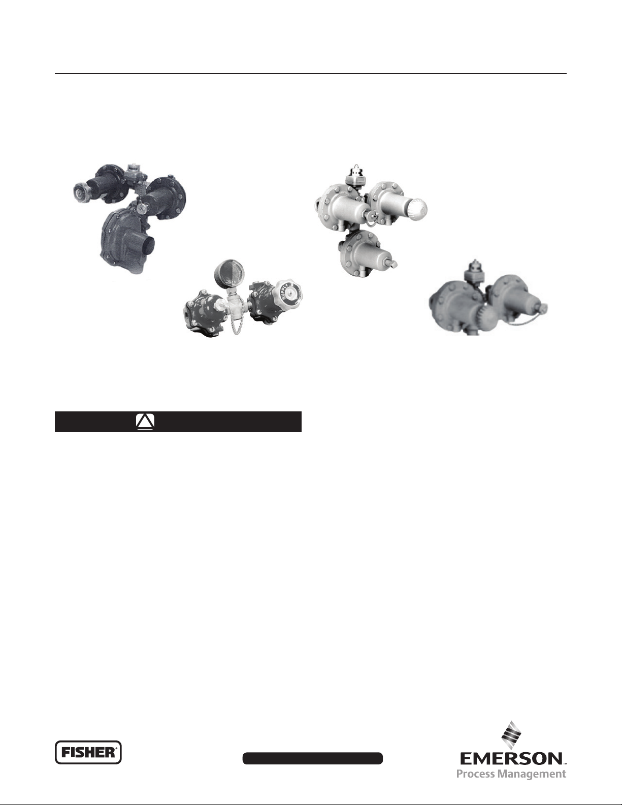
Types 749B and R130 Changeover Manifolds
TYPE HSRL-749B
TYPE R130/21
Figure 1. Changeover Manifolds and Regulator Assemblies
WARNING
!
Failure to follow these instructions or
to properly install and maintain this
equipment could result in an explosion
and/or re causing property damage and
personal injury or death.
Fisher® equipment must be installed,
operated, and maintained in accordance
with federal, state, and local codes
and Emerson Process Management
Regulator Technologies, Inc.
instructions. The installation in most
states must also comply with NFPA No.
54 and 58 standards.
Only personnel trained in the proper
procedures, codes, standards, and
regulations of the LP-Gas industry
should install and service this equipment.
TYPE 64SR/122
TYPE 749B/21
Things to tell the Gas Customer:
1. Point out the regulator’s vent to the customer (or
vent assembly or vent tube), and stress that this
opening must remain unobstructed at all times.
Tell the customer to be sure to check the vent
opening after a freezing rain, sleet storm, or snow
to make sure ice has not formed in the vent.
2. Show the customer the shutoff valve on the
container. The customer should close this valve
immediately if gas is smelled, appliance pilot lights
fail to stay on or appear higher than usual, or any
other abnormal situation occurs.
3. Tell the customer to call your company to service
the regulator if the regulator vents gas or a leak
develops in the system. Only a qualied gas
service person should install or service
the regulator.
www.sherregulators.com
D450078T012
Page 2
Types 749B and R130
Specications
The Specications table lists the specications for the regulators. Contact the factory if the regulators are to be used on
any sevice other than LP-Gas, natural gas, or air.
Changeover Manifold Assemblies
CAPACITY BTU/HR.
PROPANE
1,475,000
1,500,000
1. Based on 100 psig / 6.9 bar inlet, reserve setting.
(1)
(1)
TYPE
R130/21 1/4-inch FNPT 1/4-inch FNPT 45 psig 3.1 bar 30 psig 2.1 bar
749B/21 1/2-inch FNPT 1/2-inch FNPT 15 psig 1.0 bar 5 psig 0.35 bar
INLET
CONNECTIONS
OUTLET
CONNCETIONS
Commercial Automatic Changeover Regulators
CAPACITY
BTU/HR.
PROPANE
1,575,000 HSRL-749B 1/2-inch FNPT 3/4-inch FNPT 11-inches w.c. 27 mbar 9 to 13-inches w.c. 22 to 32 mbar P100A
1,210,000 64SR/122 1/2-inch FNPT 1/2-inch FNPT 10 psig 0.69 bar 5 to 20 psig 0.35 to 1.4 bar - - -
TYPE
INLET
CONNECTION
OUTLET
CONNCETION
OUTLET
PRESSURE SETTING
OUTLET PRESSURE SETTING
Supply Setting Reserve Setting
OUTLET
ADJUSTMENT RANGE
MOUNTING
BRACKET
Maximum Inlet Pressure
250 psig / 17.2 bar
Introduction
Scope of the Manual
The Instruction Manual covers installation and
maintenance for the Types 749B, R130 changeover
manifolds and the Types 64SR/122 and HSRL-749B
commercial automatic changeover regulators.
Description
Changeover Manifold Assemblies
Type R130/21—Composed of two Type 67C
regulators and a special 0 to 60 psig / 0 to 4.1 bar
pressure gauge, the Type R130/21 delivers a 45 psig /
3.1 bar outlet pressure on supply and 30 psig /
2.1 bar on reserve. The gauge, which serves as the
changeover indicator, is painted red from 0 to 35 psig /
0 to 2.4 bar. When the dial reads in the 0 to 35 psig /
0 to 2.4 bar range, it indicates that the manifold has
switched from the supply to the reserve cylinder.
Temperature Range
-20 to 160°F / -29 to 71°C
CAUTION
Capacity of all these changeover
manifolds is dependent on the size of
the second stage regulator with which
they are used.
WARNING
!
If the manifolds are used on nal-stage
(pounds-to-pounds), a relief valve is
required in the downstream system.
Commercial Automatic Changeover Regulators
Designed for large capacity multi-cylinder or tank
installations, these regulators are used on such
applications as bakeries, motels, restaurants, and
grain dryers. The manifold portion of the assembly
(Type 749B/21) consists of two Type 64 regulators and
a direct mounted Type 803 indicator.
Type 749B/21—Large capacity changeover manifold
for commercial and industrial applications. It consists of
two Type 64 regulators and a Type 803 direct indicator.
The assembly is used primarily in conjunction with
either a Type HSRL or 64SR regulator. The standard
outlet setting is 15 psig / 1.0 bar (supply) and 5 psig /
0.34 bar (reserve).
2
Type HSRL-749B—For low-pressure service. The
Type HSRL second-stage portion has the “drip lip”
vent feature and built-in travel stop to open the internal
relief valve.
Type 64SR/122—For high-pressure (pounds to
pounds) service with the second-stage composed of
Type 64SR that has internal relief.
Page 3
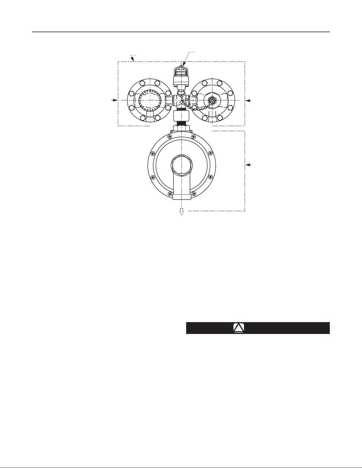
1ST STATE CHANGEOVER
MANIFOLD SECTION
Types 749B and R130
PRESSURE GAUGE OR
INDICATOR WITH RED
WARNING FLAG
C
O
N
R
T
E
R
O
H
S
L
I
I
N
E
U
D
S
S
A
A
F
M
SUPPLY INLET
SUPPLY
VENT
POINT ALL VENTS DOWN
T40469
FINAL STAGE REGULATOR
Figure 2. Changeover Regulator
Operation
The Changeover Manifold (Figure 2) consists of two
regulators (supply and reserve) and an indicator
that denotes when the reserve regulator is in
operation. The “Supply” regulator has the handwheel
labelled “SUPPLY”.
Open both container valves slowly. Gas will now ow
from both containers through the piping into the
rst-stage section of the regulator manifold by way of
the inlet ttings. When the reserve pressure setting
(see Specications) is reached in the rst-stage
regulator manifold, the disk assembly in the reserve
regulator will shutoff gas from the “Reserve” container.
Gas from the “Supply” container will continue to enter
the supply regulator until the supply pressure setting
(see Specications) is maintained. Any second or
nal stage regulator reduces this pressure for use by
the appliance.
The “Supply’’ side of the regulator manifold will
continue to supply gas as long as sufcient gas
remains in the “Supply” container. When pressure
in the “Supply” side container drops to the reserve
setting, the “Reserve” side of the regulator manifold
C
O
N
R
T
E
R
O
H
S
L
I
I
N
E
U
D
S
S
A
A
F
M
s
VENT
O
N
C
T
R
R
E
O
H
L
S
I
S
N
I
E
U
D
S
A
F
A
M
VENT
RESERVE INLET
FINAL STAGE
REGULATOR
will open and maintain the reserve setting to the
second-stage regulator, which continues to regulate
the pressure to the appliance. At the time the
pressure in the “Supply” container drops to the
reserve side pressure, a red warning ag appears in
the indicator window or the pressure gauge pointer
drops into the red section (Type R130) and also on
the remote indicator if one is used.
Switching Supply Containers
WARNING
!
The open line (pigtail or hose) must be
capped because gas will escape to the
atmosphere through the open
connection if pressure in the supply
cylinder drops to the reserve pressure
setting (red indicator ag visible).
Refer to Figure 3. Once the “Supply” container is
empty, remove the “Reserve” cap (key 4) which is
attached to the chain assembly (key 8) and the “Supply”
handwheel (key 3) by turning them counter-clockwise.
Do not remove the adjusting screw (key 5) or the nut
(key 1) on the adjusting screw. Screw the “Supply”
3
Page 4

Types 749B and R130
handwheel into the old reserve side regulator until
it cannot be turned any further. This side is now
the new “Supply” side. Screw the cap and the
chain assembly into the old supply side until it cannot
be turned any further. This side is now the new
“Reserve” side.
When the “Supply” handwheel is installed in the new
side, the red ag in the indicator should disappear or
the pointer in the gauge should move out of the red.
CAUTION
There will still be pressure in the empty
container equal to the “Reserve” side
manifold setting.
If the containers are cylinders, close the cylinder valve
of the empty cylinder to prevent air from entering
the cylinder and disconnect the cylinder. Clean the
new cylinder’s valve outlet. After the new cylinder
is in place, slowly open the cylinder valve. The new
cylinder now becomes the reserve cylinder. If only one
cylinder, the new supply cylinder, is left connected, the
open line (pigtail or hose) must be capped to prevent
leakage or contamination.
Installation
WARNING
!
Personal injury or system damage may
result if these regulators are installed
without appropriate overpressure
protection. Maximum emergency outlet
pressure for the Type 67C regulators
used on the Type R130 is 50 psig /
3.4 bar over the outlet pressure setting,
or 100 psig / 6.9 bar, whichever is greater.
Maximum emergency outlet pressure for
the 64 regulators used on the
Type 749B is 220 psig / 15.2 bar.
Maximum emergency outlet pressure
for the Type HSRL nal stage regulator
is 3 psig / 0.21 bar above setpoint.
Outlet pressures greater than these
above set point may cause damage to
regulator parts, leaks in the regulator,
or personal injury due to bursting of
pressure-containing parts or explosion of
accumulated gas.
If the regulator is exposed to an
overpressure condition, it must be
inspected for any damage that may
have occurred.
Large volumes of gas may discharge
through the regulator vent during
internal relief valve operation which
can result in re or explosion from
accumulated gas.
All vents should be kept open to permit
the free ow of air into and out of the
regulator. Protect openings against the
entrance of rain, snow, ice formation,
paint, mud, insects, or any other foreign
material that could plug the vent.
LP-Gas may discharge to the
atmosphere through the vent. An
obstructed vent which limits air or
gas ow can cause abnormally high
pressure that could result in personal or
property damage.
Make sure gas ow through the regulator is in the
correct direction. There are two 1/4-inch NPT
(Type R130) or two 1/2-inch NPT (Type 749B) inlet
connections and the “Outlet” connection is clearly
marked on the regulator. The installation should
be adequately protected from vehicular trafc and
damage from other external sources.
Install the regulator high enough above ground level
- at least 18 inches / 457 mm - so that rain splatter
cannot freeze in the vents. Whether a protective hood
is used or not, do not install the regulator in a location
where there can be excessive water accumulation or
ice formation, such as directly beneath a downspout,
gutter, or roof line of a building.
A regulator installed outdoors without a protective
hood must have its vent pointed vertically down, see
Figure 2, to allow condensate to drain. This minimizes
the possibility of freezing and of water or other foreign
material entering the vent and interfering with proper
operation. Some installations, such as in areas with
heavy snow fall, require a hood or enclosure to protect
the regulator. Before installing the regulator, check for
damage which might have occurred in shipment. Also
check for and remove any dirt or foreign matter which
may have accumulated in the regulator body or the
pipeline. The outlets of the container valves should be
cleaned to remove dirt or water. One method of doing
4
Page 5

A A
Types 749B and R130
T80219
CHANGEOVER REGULATOR SPRING
Zinc
1D7515
Blue
1D6659
Blue
T14058
5
3
Figure 3. Assembly Drawing
Table 1. Manifold Spring Rates
749B Series (Type 64 Manifold Regulators)
RESERVE OUTLET PRESSURE STANDARD
SETTING AND RANGE
6 psi / 0.41 bar
Adjustable Range
3 to 11 psi / 0.21 to 0.76 bar
5 psi / 0.35 bar
Adjustable Range
5 to 15 psi / 0.35 to 1.0 bar
R130 Series (Type 67C Manifold Regulators)
30 psi / 2.1 bar
Adjustable Range
5 to 40 psi / 0.35 to 2.8 bar
SUPPLY
8
5
1
4
VIEW A-A
APPROXIMATE SUPPLY
PRESSURE ABOVE RESERVE SETTING
9 psi / 0.62 bar
20 psi / 1.4 bar
14 psi / 0.97 bar
this is by cracking the container valve open for a short
time to blow out the dirt. Apply pipe compound to the
male threads of the pipe.
A relief valve is required downstream of all the
regulators (except Types 64SR or HSRL) used on
nal-stage service. Both the Types 64SR and HSRL
nal-stage regulators have an internal relief valve. The
internal relief valve opens when downstream pressure
reaches approximately 125% to 250% above the set
point for the Type 64SR or 200% to 300% above the
setpoint for the Type HSRL.
WARNING
!
Be sure that the changeover manifold
regulator assembly is supplying the
correct pressure to the appliance.
Failure to provide the correct pressure
to the appliance can result in personal
injury from re and or explosion or
damage downstream equipment.
5
Page 6

Types 749B and R130
20 6
12
5
7
L
T20923
APPLY LUBRICANT (L)
8
Figure 4. Indicator Assembly Drawing
To Change Settings in the Field:
See Figure 3.
1. Remove both the supply handwheel (key 3)
and reserve cap (key 4) from 1st stage
manifold regulators.
2. Install a pressure gauge on the outlet side of the
manifold, ahead of any nal stage regulator.
3. Close the left side of the container shutoff valve.
Loosen the adjusting screw nut (key 1) on the
right side manifold regulator. Rotate the right side
adjusting screw (key 5) clockwise to increase the
reserve pressure or counter clockwise to decrease
the reserve pressure. Monitor the manifold outlet
pressure with the pressure gauge. Reserve
pressure range should remain within the limits
specied in Table 1.
WARNING
!
Exceeding the reserve limits specied
in Table 1 for a given spring will prevent
the manifold regulator from being able
to produce the desired supply side
pressures and could cause the loss of
pressure control on the supply side.
3
4
1
2
9
4. Close the right side of the container valve and
open the left side container valve. Loosen
the adjusting screw nut (key 1) on the left side
manifold regulator. Rotate the left side adjusting
screw (key 5) clockwise to increase the reserve
pressure or counter clockwise to decrease the
reserve pressure.
5. IMPORTANT: Set both manifold regulators to
the same reserve pressure setting. Tighten both
adjusting screw nuts (key 1).
6. The indicator should show all red at the reserve
setting desired.
Replace the supply handwheel (key 3). The
indicator should show all silver.
If the reserve setting exceeds 8 psi / 0.55 bar,
then the Type 803-21 indicator may not operate
with the desired range. If the indicator does not
show all red at the reserve pressure or all silver at
the supply pressure, then some adjustment to the
indicator will be required, or a pressure gauge will
have to be installed in place of the indicator.
7. See Figure 4. To adjust the indicator remove
the screw (key 6) and the lens (key 3). Using
a small slotted screw driver, turn the adjusting
screw clockwise to increase the pressure or
6
Page 7

Types 749B and R130
counterclockwise to decrease the pressure. The
indicator should show red at about 3 psi / 0.21 bar
above the new reserve setting. The indicator should
show silver at about 6.5 psi / 0.45 bar above the new
reserve setting.
CAUTION
Set both manifold regulators to the
same reserve pressure setting. The
supply handwheel when installed, will
automatically provide the additional
adjustment to set the supply pressure.
Maintenance
WARNING
!
To avoid personal injury or equipment
damage, do not attempt any maintenance
or disassembly without rst isolating
the regulator from system pressure and
relieving all internal pressure.
Regulators that have been disassembled
for repair must be tested for proper
operation before being returned to
service. Only parts manufactured by
Fisher® should be used for repairing
Fisher regulators. Relight pilot lights
according to normal startup procedures.
Due to normal wear or damage that
may occur from external sources,
these regulators must be inspected and
maintained periodically. The frequency
of inspection and replacement of the
regulators depends upon the severity of
service conditions or the requirements
of local, state, and federal regulations.
Even under ideal conditions, these
regulators should be replaced after
15 years from the date of manufacture or
sooner should inspection reveal the need.
Visually inspect the regulator each time a gas delivery is
made for:
1. Improper installation.
2. Plugged or frozen vent.
3. Wrong regulator or no regulator in the system.
4. Internal or external corrosion.
5. Age of the regulator.
6. Any other condition that could cause the
uncontrolled escape of gas.
Failure to do the above could result in personal injury or
property damage.
Make sure the regulator vent, vent assembly, or vent
tube does not become plugged by mud, insects, ice,
snow, paint, etc. The vent screen aids in keeping the
vent from becoming plugged, and the screen should be
clean and properly installed.
Replace any regulators that have had water in their
spring case or show evidence of external or internal
corrosion. Checking for internal corrosion may require
complete removal of the adjusting screw and shut down
of the gas system. Closely examine regulators directly
connected to the container valve by means of a solid
POL adaptor (horizontal mounting) for signs of corrosion.
Correct any improper installations.
Older regulators are more likely to catastrophically fail
because of worn or corroded parts. Replace regulators
over 15 years of age; other service or environmental
conditions may dictate replacement of the regulator
before it becomes 15 years old, refer to Fisher
Bulletin LP-32.
Regulator Repair
Regulators that have been disassembled for repair
must be tested for proper operation before being
returned to service. Only parts manufactured by Fisher
should be used to repair Fisher regulators. Be sure to
give the complete type number of the regulator when
corresponding with the factory.
7
Page 8

Types 749B and R130
LP-Gas Equipment
Emerson Process Management
Regulator Technologies, Inc.
USA - Headquarters
McKinney, Texas 75069-1872, USA
Tel: +1 800 558 5853
Outside U.S. +1 972 548 3574
For further information visit www.sherregulators.com
The Emerson logo is a trademark and service mark of Emerson Electric Co. All other marks are the property of their prospective owners. Fisher is a mark owned by Fisher Controls International LLC,
a business of Emerson Process Management.
The contents of this publication are presented for informational purposes only, and while every effort has been made to ensure their accuracy, they are not to be construed as warranties or
guarantees, express or implied, regarding the products or services described herein or their use or applicability. We reserve the right to modify or improve the designs or specications of such
products at any time without notice.
Emerson Process Management does not assume responsibility for the selection, use or maintenance of any product. Responsibility for proper selection, use and maintenance of any Emerson
Process Management product remains solely with the purchaser.
©Emerson Process Management Regulator Technologies, Inc,. 2002, 2012; All Rights Reserved
 Loading...