

Page 1
Instruction Manual
Form 1292
July 2007
655 and 655R Actuators
Type 655 and 655R Actuators
for Self-Operated Control
Contents
Introduction 1. . . . . . . . . . . . . . . . . . . . . . . . . . . . . . .
Scope of Manual 1. . . . . . . . . . . . . . . . . . . . . . . . .
Description 1. . . . . . . . . . . . . . . . . . . . . . . . . . . . . .
Specifications 2. . . . . . . . . . . . . . . . . . . . . . . . . . . .
Installation 2. . . . . . . . . . . . . . . . . . . . . . . . . . . . . . . .
Actuator Mounting 3. . . . . . . . . . . . . . . . . . . . . . . .
Loading Connections 6. . . . . . . . . . . . . . . . . . . . . .
Startup 6. . . . . . . . . . . . . . . . . . . . . . . . . . . . . . . . . . .
Startup for Pressure-Reducing Service 6. . . . . .
Startup for Pressure-Relief Service 7. . . . . . . . .
Adjustment for Pressure-Reducing or
Pressure-Relief Service 7. . . . . . . . . . . . . . . . .
Shutdown 7. . . . . . . . . . . . . . . . . . . . . . . . . . . . . . . . .
Maintenance 7. . . . . . . . . . . . . . . . . . . . . . . . . . . . . .
Actuator 8. . . . . . . . . . . . . . . . . . . . . . . . . . . . . . . . .
Top-Mounted Handwheel 10. . . . . . . . . . . . . . . . .
Parts Ordering 12. . . . . . . . . . . . . . . . . . . . . . . . . . . .
Parts List 12. . . . . . . . . . . . . . . . . . . . . . . . . . . . . . . .
Introduction
W0466-1 / IL
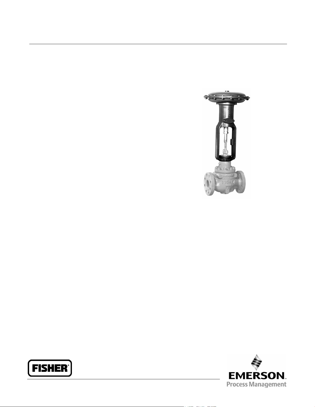
Figure 1. Type 655-ED Pressure-Reducing Valve
Scope of Manual
This instruction manual provides installation,
adjustment, maintenance, and parts ordering for the
Type 655 and 655R actuators and the top-mounted
handwheel. Refer to separate instruction manuals
for information about valves and accessories used
with these actuators.
Do not install, operate, or maintain 655 and 655R
actuators without first D being fully trained and
qualified in valve, actuator, and accessory
installation, operation, and maintenance, and
D carefully reading and understanding the contents
of this manual. If you have any questions about
these instructions, contact your Emerson Process
Managementt sales office before proceeding.
Description
Type 655 and 655R actuators (figure 1) are
pressure-actuated, spring-and-diaphragm actuators
used in conjunction with various valves to provide
control for a wide variety of pressure regulation
applications. Type 655 actuators are used for
pressure-reducing service when mounted on
push-down-to-close valves such as the Design ED
and ET valves. Type 655R actuators are used for
pressure-relief service when mounted on
push-down-to-open valves such as the Design EDR
and ETR valves. Both types are self-operated and
direct-acting; that is, increasing pressure in the
diaphragm casing forces the actuator stem
downward, and decreasing the pressure allows the
actuator spring to lift the actuator stem upward.
Note
Neither Emerson, Emerson Process
Management, nor any of their affiliated
entities assumes responsibility for the
selection, use and maintenance of any
product. Responsibility for the
selection, use, and maintenance of any
product remains with the purchaser
and end-user.
www.Fisher.com
D100305X012
Page 2
655 and 655R Actuators
ACTUATOR
ACTUATOR
Instruction Manual
Form 1292
July 2007
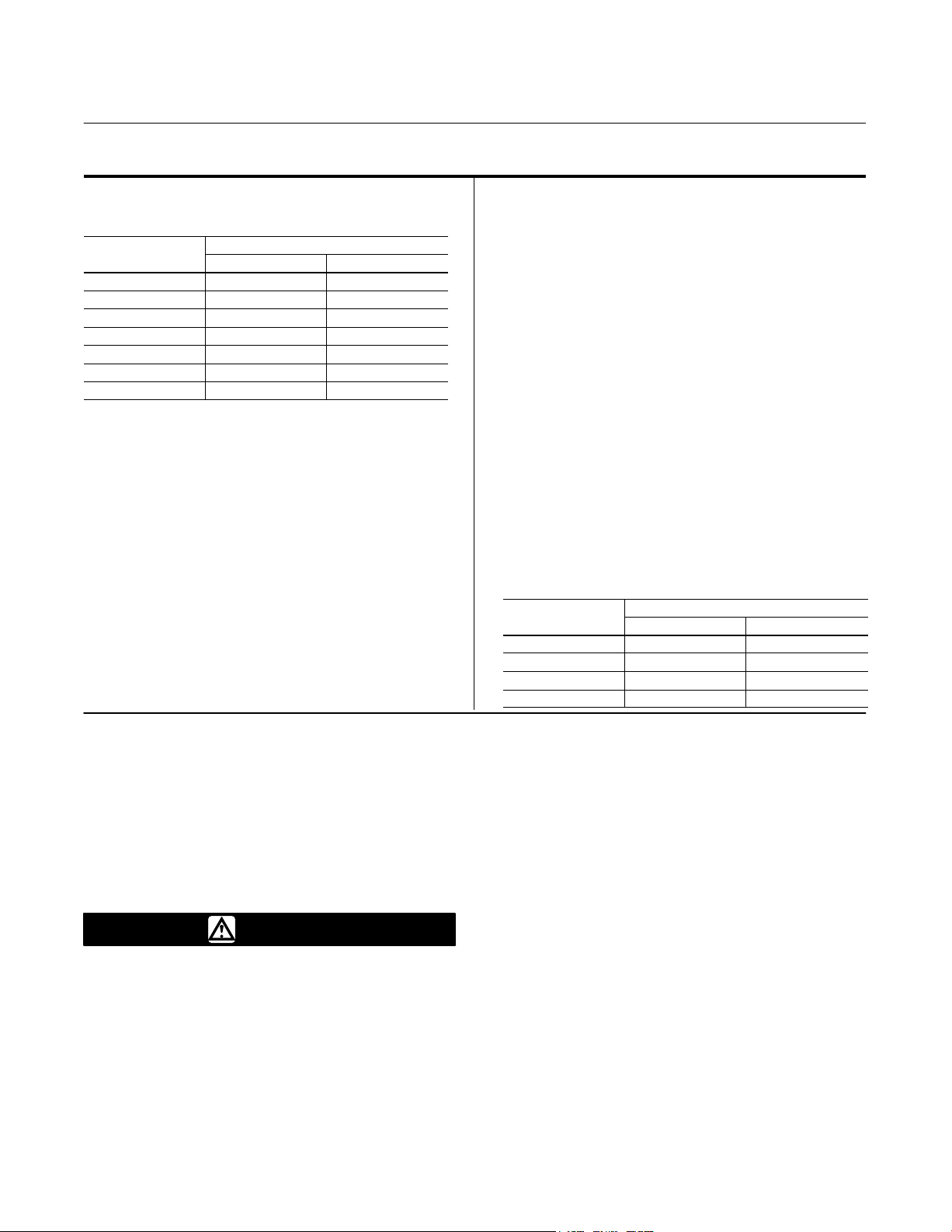
Table 1. Specifications
Actuator Sizes and Maximum Casing Pressures
ACTUATOR
SIZE
3A, 4A 17.2 250
3B, 4B 12.1 175
32, 42 6.9 100
33, 43 4.5 65
34, 44 3.1 45
35, 45 2.1 30
36, 46 1.0 15
MAXIMUM CASING PRESSURE
Bar
Psig
Actuator Pressure Setting Ranges
See table 2
Actuator Yoke Boss and Valve Stem Connection
Diameters
Sizes 3A through 36: 54 mm (2-1/8 inch) yoke
boss with 9.5 mm (3/8 inch) stem connection
Sizes 4A through 46: 71 mm (2-13/16 inch) yoke
boss with 12.7 mm (1/2 inch) stem connection
Maximum Travel
Sizes 3A and 4A: 11 mm (0.4375 inch) plus
3 mm (0.125 inch) for seating
All Other Sizes: 19 mm (0.75 inch) plus 3 mm
(0.125 inch) for seating
Effective Diaphragm Area
See table 3
Spring Rate
See key 6 in the parts list section
Temperature Capabilities
–29 to 82_C (–20 to 180_F) with standard
diaphragm material. For the fluid and temperature
capabilities of nonstandard diaphragm materials,
consult your Emerson Process Management
sales office
Casing Pressure Connections
1/2 NPT internal
Approximate Weights
ACTUATOR
SIZE
3A, 3B, 32, 33 20 45
34, 35, 36 23 50
4A, 4B, 42, 43 29 65
44, 45, 46 34 75
APPROXIMATE WEIGHT
Kg
Lb
Specifications
Specifications for the Type 655 and 655R actuators
are shown in table 1. Information for a specific
actuator is also found on the nameplate of that
actuator.
Installation
WARNING
To avoid personal injury or property
damage caused by bursting of
pressure-retaining parts, be certain the
service conditions do not exceed the
casing pressure limits listed in table 1.
Use pressure-limiting or
pressure-relieving devices to prevent
service conditions from exceeding
these limits.
2
Always wear protective gloves,
clothing, and eyewear when
performing any installation operations
to avoid personal injury.
Check with your process or safety
engineer for any additional measures
that must be taken to protect against
process media.
If installing into an existing
application, also refer to the WARNING
at the beginning of the Maintenance
section in this instruction manual.
Type 655 and 655R actuators are normally shipped
mounted on a valve. Refer to the appropriate valve
instruction manual when installing the valve in the
pipeline. If the actuator is shipped separately or if it
is necessary to mount the actuator on the valve,
perform the procedures described in the Actuator
Mounting portion of this section.
Page 3

Instruction Manual
Form 1292
July 2007
655 and 655R Actuators
CAUTION
To avoid premature wear of the
diaphragm due to debris in the
pressure line to the diaphragm, install
a strainer in the pipeline ahead of the
regulator or relief valve.
Before installing the actuator, inspect it for any
damage. Also, keep any adjacent piping clean and
free of pipe scale or other debris that could possibly
disrupt service. It is recommended that a strainer be
installed in the pipeline ahead of the regulator or
relief valve to protect it while in service. And a
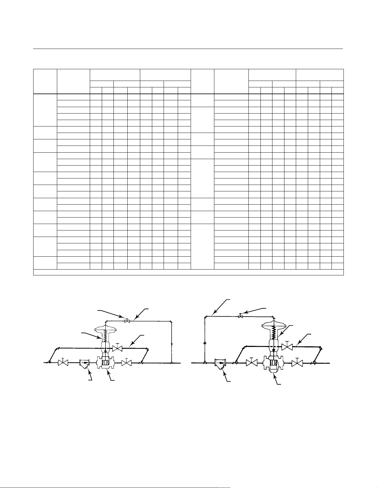
conventional three-valve bypass (see figure 2)
should be placed around the regulator or relief valve
to permit continuous operation when it is being
installed or repaired.
Actuator Mounting
The actuator may be installed either above or below
the pipeline.
plate (key 4) against the upper diaphragm casing
(key 1).
2. Perform the following steps as appropriate for
either push-down-to-close or push-down-to-open
valve action.
CAUTION
In the following procedures, do not
rotate the valve plug while it is seated
since this may cause damage to the
seating surfaces and thereby allow
excessive leakage. Also, during travel
adjustment, use tools carefully to
avoid damaging the valve plug stem. A
damaged stem could cut the packing
and allow leakage.
For Push-Down-To-Close Valves:
a. Place the actuator part way over the valve
stem. Then, place the yoke locknut over the valve
stem, and slide the travel indicator disk (key 11, if
used) on top of the hex nuts (key 12).
CAUTION
In steam service applications, avoid
premature wear of the diaphragm, due
to high temperature steam, by
installing the valve with the actuator
positioned below the pipeline.
If the regulator or relief valve is to be used for steam
service, the valve should be installed with the
actuator positioned below the pipeline, and the
control line should be sloped down toward the
diaphragm casing. This is to ensure that any forming
condensate will maintain a water seal to protect the
diaphragm.
The following procedure describes how to mount the
actuator on either a push-down-to-close or a
push-down-to-open valve so that the actuator stem
and valve stem thread engagement will allow full
travel and proper shutoff. Refer to figure 3 for
actuator mounting components. Key numbers refer
to figure 4 unless otherwise stated.
1. Turn the adjusting screw (key 10) into the yoke
(key 7) to force the diaphragm (key 2) and diaphragm
b. Set the actuator onto the valve body. The
length of the valve stem will prevent the actuator
yoke (key 7) from sitting on the bonnet properly.
Measure the distance from the bottom of the
actuator yoke to the mating shoulder on the
bonnet, and then add the valve plug travel to this
measurement.
c. Raise the actuator so the valve plug can be
lifted off the seat ring.
Note
Either turn the actuator, or tighten the
hex nuts together, and use a wrench
on the hex nuts to turn the valve plug
and stem assembly.
Thread the valve stem into the actuator stem the
distance measured in the previous step.
d. Lower the actuator onto the valve body
bonnet, and tighten the yoke locknut.
e. Connect the pressure control lines as
described in the Loading Connection portion of
this section.
3
Page 4
655 and 655R Actuators
SPRING PART
SPRING PART
SIZE
NUMBER
SIZE
NUMBER
3A, 4A
3B, 4B
33, 43
36, 46
Instruction Manual
Form 1292
July 2007
Table 2. Actuator Pressure-Setting Ranges
ACTUA-
3A, 4A
3B, 4B
32, 42
33, 43
1. Effects of packing box friction, unbalance, and weight of valve plug not considered in calculations.
TOR
3B
4B
32
42
33
43
34
SPRING PART
NUMBER
1E792427082 5.4 78 12.0 174 4.5 65 10.1 146
1F714327092 3.0 44 9.3 135 3.0 43 8.2 119
1F176927092 2.2 32 6.6 96 2.6 37 5.9 85 1E792427082 0.6 9.0 1.4 20 0.5 7.0 1.1 16
1F176827092 1.8 26 5.4 78 2.3 34 5.2 75
1F176727032 1.3 19 4.1 59 1.4 20 3.9 57
1E793327082 3.4 50 7.4 107 3.0 43 4.4 64 1F176827092 0.2 2.8 0.6 8.5 0.1 2.0 0.6 8.5
1E795427082 2.9 42 6.3 92 2.4 35 4.4 64
1E793327082 3.4 50 7.4 107 3.0 43 6.1 89
1E795427082 2.9 42 6.3 92 2.4 35 5.3 77
1E792427082 2.4 35 5.4 78 2.0 29 4.4 64
1F714327092 1.4 20 4.1 60 1.3 19 3.7 53 1E792427082 0.4 5.8 0.9 13 0.3 5.0 0.8 11
1F176927092 1.0 14 3.0 43 1.2 17 2.6 38 1F714327092 0.2 3.3 0.7 10 0.2 3.2 0.6 9.0
1E793327082 2.2 32 4.5 65 1.8 26 2.6 38
1E795427082 1.8 26 3.8 55 1.5 22 2.6 38
1E793327082 2.2 32 4.5 65 1.8 26 3.7 53 1F176727032 0.1 1.5 0.3 4.4 0.1 1.5 0.3 4.2
1E795427082 1.8 26 3.8 55 1.5 22 3.1 45 1F714427112 0.07 1.0 0.2 2.9 0.09 1.3 0.2 2.8
1E792427082 1.5 22 3.2 47 1.2 18 2.6 38
1F714327092 0.8 12 2.5 36 0.8 12 2.1 31
1E793327082 1.3 19 2.8 40 1.1 16 1.7 24
1E795427082 1.1 16 2.3 34 0.9 13 1.7 24
1E793327082 1.3 19 2.8 40 1.1 16 2.3 33 1E792427082 0.3 4.1 0.6 9.2 0.2 3.5 0.5 7.7
1E795427082 1.1 16 2.3 34 0.9 13 1.9 28 1F714327092 0.2 2.3 0.5 7.1 0.2 2.3 0.4 6.3
1E792427082 1.0 14 2.0 29 0.8 11 1.7 24 1F176927092 0.1 1.7 0.4 5.1 0.1 2.0 0.3 4.5
1F714327092 0.5 7.0 1.5 22 0.5 7.0 1.4 20
1F176927092 0.4 5.2 1.1 16 0.3 5.0 1.1 16
1E793327082 0.9 13 1.9 28 0.8 11 1.1 16 1F714427112 0.05 0.7 0.1 2.1 0.06 0.9 0.1 2.0
1E795427082 0.8 11 1.6 23 0.6 9.0 1.1 16 1F713027112 0.02 0.34 0.08 1.1 0.05 0.7 0.07 1.0
PRESSURE
REDUCTION
Minimum Maximum Minimum Maximum
Bar Psig Bar Psig Bar Psig Bar Psig
PRESSURE
RELIEF
ACTUA-
TOR
44
34, 44
35
45
35, 45
36
46
36, 46
(1)
PRESSURE
SPRING PART
NUMBER
1E793327082 0.9 13 1.9 28 0.8 11 1.6 23
1E795427082 0.8 11 1.6 23 0.6 9.0 1.3 19
1F714327092 0.3 5.0 1.1 16 0.3 5.0 0.9 13
1F176927092 0.3 3.8 0.8 11 0.3 4.0 0.7 10
1E793327082 0.6 8.3 1.2 18 0.5 7.0 0.8 11
1E795427082 0.5 7.0 1.0 15 0.4 5.5 0.8 11
1E793327082 0.6 8.3 1.2 18 0.5 7.0 1.0 15
1E795427082 0.5 7.0 1.0 15 0.4 5.5 0.9 13
1F176927092 0.2 2.4 0.5 7.2 0.2 2.8 0.4 6.3
1F176827092 0.1 2.0 0.4 5.9 0.2 2.5 0.4 5.5
1E793327082 0.4 5.8 0.9 13 0.3 5.0 0.5 7.7
1E795427082 0.3 4.9 0.8 11 0.3 4.2 0.5 7.7
1E793327082 0.4 5.8 0.9 13 0.3 5.0 0.8 11
1E795427082 0.3 4.9 0.8 11 0.3 4.2 0.6 9.0
1F176827092 0.09 1.3 0.3 4.2 0.1 1.8 0.3 4.0
1F176727032 0.07 1.0 0.2 3.1 0.08 1.1 0.2 3.0
REDUCTION
Minimum Maximum Minimum Maximum
Bar Psig Bar Psig Bar Psig Bar Psig
PRESSURE
RELIEF
TYPE 655 ACTUATOR
13A6502-A
13A6503-A
A1628-1 / IL
4
1/2 NPT CONTROL LINE
LARGE PORT
NEEDLE VALVE
STRAINER
1/2 NPT
CONTROL LINE
BYPASS LINE
DIRECT-ACTING BALANCED
PLUG VALVE BODY
STRAINER
LARGE PORT NEEDLE VALVE
REVERSE-ACTING BALANCED
PLUG VALVE BODY
PRESSUREĆREDUCING INSTALLATION PRESSUREĆRELIEF INSTALLATION
Figure 2. Typical Installation Schematics
TYPE 655R ACTUATOR
BYPASS LINE
Page 5

Instruction Manual
ACTUA
TOR
Form 1292
July 2007
655 and 655R Actuators
Table 3. Effective Diaphragm Area
ACTUA-
TOR
SIZE
3A, 4A 66 10.2 62 9.6 61 9.5 61 9.4 59 9.2 59 9.1 57 8.9 56 8.7 - - - - - - - - - - - -
3B, 4B 152 23.5 139 21.6 136 21.1 134 20.8 132 20.5 131 20.3 130 20.1 128 19.8 117 18.1 103 16.0
32, 42 258 40.0 235 36.4 227 35.2 221 34.2 210 32.6 205 31.8 200 31.0 195 30.3 182 28.2 170 26.4
33, 43 406 63.0 374 58.0 366 56.8 358 55.5 345 53.5 340 52.7 335 52.0 330 51.2 318 49.3 307 47.6
34, 44 600 93.0 547 84.8 534 82.8 523 81.0 508 78.8 502 77.8 497 77.0 490 76.0 474 73.5 465 72.0
35, 45 865 134.0 834 129.2 821 127.2 809 125.4 788 122.2 777 120.5 768 119.0 759 117.6 736 114.1 723 112.0
36, 46 1230 190.0 1170 181.5 1150 179.0 1140 177.0 1120 173.5 1110 172.3 1100 171.0 1100 169.8 1070 166.5 1050 163.5
1. For the spring rates of a particular spring, see key 6 in the Parts List section.
0 3 (0.125) 5 (0.1875) 6 (0.25) 10 (0.375) 11 (0.4375) 13 (0.5) 14 (0.5625) 19 (0.75) 22 (0.875)
Cm2In.2Cm2In.2Cm2In.2Cm2In.2Cm2In.2Cm2In.2Cm2In.2Cm2In.2Cm2In.2Cm2In.
TRAVEL DOWN FROM UPPER CASING STOP, mm (IN.)
DIAPHRAGM PLATE
DOWN TRAVEL STOP
(1)
2
ACTUATOR STEM
ADJUSTING SCREW
TRAVEL INDICATOR
STEM HEX NUTS
VALVE STEM
YOKE LOCKNUT
SEAT RING
VALVE PLUG
VALVE PLUG
SEAT RING
DV3742-B
DH4667-B
31A0223-B
B0816-1 / IL
PUSHĆDOWNĆTOĆCLOSE VALVE
PUSHĆDOWNĆTOĆOPEN VALVE
Figure 3. Actuator/Valve Components
5
Page 6

655 and 655R Actuators
Instruction Manual
Form 1292
July 2007
f. Stroke the actuator, and measure the stem
movement to check travel. If the movement is
more than full travel, turn the valve stem out of
the actuator stem the amount of over-travel. If
movement is less than full travel, turn the valve
stem into the actuator stem the amount of
under-travel.
For Push-Down-To-Open Valves:
a. Place the actuator, yoke locknut, and travel
indicator disk (key 11, if used) over the valve
stem. Support the actuator above the valve body
so the actuator stem and valve stem do not
contact when the valve plug is seated.
b. Connect the pressure control lines as
described in the Loading Connection portion of
this section.
c. Move the valve plug, by hand, from the seated
to the open position, and make sure that valve
stem movement corresponds to the desired
travel.
d. Stroke the actuator until the diaphragm plate
(key 4) contacts the down travel stop (see
figure 3).
e. With the valve plug positioned as described in
step c above, lower the actuator until the actuator
stem contacts the valve stem, and measure the
distance from the bottom of the actuator yoke to
the mating shoulder on the bonnet.
f. Thread the valve stem into the actuator stem
until the thread engagement is equal to the
distance measured in the previous step. Tighten
the hex nuts (key 12) together, and use a wrench
to turn the valve plug and stem assembly.
g. Lower the actuator onto the valve body
bonnet, and tighten the yoke locknut.
h. Stroke the actuator, and measure the stem
movement to check travel. If the movement is
more than full travel, turn the valve stem into the
actuator stem the amount of over-travel. If the
movement is less than full travel, turn the valve
stem out of the actuator stem the amount of
under-travel.
3. After correct travel has been obtained, tighten the
hex nuts (key 12) against the actuator stem (key 8),
and tighten the yoke locknut with a hammer and
punch.
Note
Changing the spring adjustment will
not change the actuator pressure
range for that particular spring (see
table 2). Changing the spring
adjustment merely shifts the position
of the spring either up or down so that
valve travel can coincide with the
actuator pressure setting range.
4. While monitoring loading pressure with a
pressure gauge, stroke the actuator, and then turn
the adjusting screw until the valve begins to travel at
the desired pressure. Turn the adjusting screw out of
the yoke to decrease spring compression and thus
allow the valve to begin travel at a lower loading
pressure. Turn the adjusting screw into the yoke to
increase spring compression and thus allow the
valve to begin travel at a higher loading pressure.
Loading Connections
Install the control line following the steps listed
below. Typical installations are shown in figure 2.
1. Connect the control line into either the upstream
pipeline for pressure-relief service or into the
downstream pipeline for pressure-reducing service
as shown in figure 2. Make the pipeline tap at least
four to eight pipe diameters away from the regulator
or relief valve, or any elbow, swage, or nipple, to
avoid abnormal velocities or turbulence.
2. Connect the other end of the control line to the
1/2 NPT connection in the center of the upper
diaphragm casing (key 1) or to the connection in the
handwheel body (key 28, figures 5 and 6; key 142,
figure 7).
3. Fit the control line with a large-port needle valve.
Partially closing or throttling this valve will tend to
dampen any cycling or pulsating action of the
regulator. Never completely close the needle valve
while the regulator is in operation.
Startup
The procedures for placing into operation and
adjusting the equipment for both pressure-reducing
and pressure-relief applications are described below.
Typical installation schematics are shown in figure 2.
Startup For Pressure-Reducing Service
1. Open the needle valve in the control line.
2. Open the downstream shutoff valve.
3. Close the valve in the bypass line.
6
Page 7
Instruction Manual
Form 1292
July 2007
655 and 655R Actuators
4. Slowly open the upstream shutoff valve.
Startup For Pressure-Relief Service
1. Open the needle valve in the control line.
2. Open the downstream shutoff valve.
3. Slowly open the upstream shutoff valve.
4. Close the valve in the bypass line.
Adjustment For Pressure-Reducing or
Pressure-Relief Service
The actuator is factory-set as specified on the order,
and the pressure range is stamped on the
nameplate. If a pressure setting other than the one
specified is desired, change the pressure setting by
following the procedures listed below. Be sure to
change the nameplate to indicate the new pressure
setting. The new pressure setting must not exceed
the limits given in tables 1 and 2 or in any applicable
codes.
CAUTION
To protect equipment in the process
system from a sudden release of
pressure, always use a pressure gauge
to monitor pressure when making
adjustments.
To adjust the downstream pressure setting for
pressure-reducing service, or the upstream pressure
setting for pressure-relief service, proceed as
follows. To decrease the pressure setting, turn the
adjusting screw (key 10, figure 4) counterclockwise;
to increase the pressure setting, turn the adjusting
screw clockwise. If the spring does not provide the
required pressure setting, replace it through the
following steps:
1. Disassemble the actuator by following steps 1, 3
and 4 of the Disassembly portion of the Maintenance
section.
2. Remove the diaphragm (key 2). Then, unscrew
the cap screw (key 3), and lift the diaphragm plate
(key 4) out of the actuator body.
3. Replace the spring and reassemble the actuator
by following steps 5 and 6 of the Assembly portion of
the Maintenance section.
Shutdown
For both pressure-reducing and pressure-relief
applications, refer to figure 2, and follow the
procedures described below.
1. Close the upstream shutoff valve slightly.
2. Slowly open the bypass valve while monitoring
downstream pressure.
3. Slowly close the downstream shutoff valve.
4. Close the upstream shutoff valve.
5. Close the needle valve in the control line.
Maintenance
Actuator parts are subject to normal wear and must
be inspected and replaced when necessary. The
frequency of inspection and replacement depends
on the severity of service conditions.
WARNING
Avoid personal injury or property
damage from sudden release of
process pressure or bursting of parts.
Before performing any maintenance
operations:
D Always wear protective gloves,
clothing, and eyewear when
performing any maintenance
operations to avoid personal injury.
D Disconnect any operating lines
providing air pressure, electric power,
or a control signal to the actuator. Be
sure the actuator cannot suddenly
open or close the valve.
D Use bypass valves or completely
shut off the process to isolate the
valve from process pressure. Relieve
process pressure from both sides of
the valve. Drain the process media
from both sides of the valve.
D Vent the power actuator loading
pressure and relieve any actuator
spring precompression.
D Use lock-out procedures to be
sure that the above measures stay in
effect while you work on the
equipment.
D The valve packing box may
contain process fluids that are
7
Page 8

655 and 655R Actuators
Instruction Manual
Form 1292
July 2007
pressurized, even when the valve has
been removed from the pipeline.
Process fluids may spray out under
pressure when removing the packing
hardware or packing rings, or when
loosening the packing box pipe plug.
D Check with your process or safety
engineer for any additional measures
that must be taken to protect against
process media.
The maintenance instructions are divided into two
sections: Actuator and Top-Mounted Handwheel.
Actuator
This procedure describes how the actuator can be
completely disassembled and assembled. When
inspection or repairs are required, disassemble only
those parts necessary to accomplish the job; then,
start the assembly at the appropriate step.
Key numbers refer to figure 4.
Disassembly
CAUTION
following procedure, make sure the
adjusting screw (key 10) remains
screwed into the yoke (key 7).
a. Loosen the two hex nuts (key 12).
b. Loosen the yoke locknut (figure 3) with a
hammer and punch, and unscrew it from the
valve bonnet.
c. While lifting the actuator so that the valve plug
is not forced against the seat, rotate the entire
actuator until the actuator stem disengages
completely from the valve plug stem.
For Push-Down-To-Open Valves:
a. Turn the adjusting screw (key 10)
counterclockwise to relieve all spring
compression. Then, move the valve plug, by
hand, off the seat.
b. Loosen the hex nuts (key 12), and unscrew
the valve plug stem out of the actuator stem as
far as it will go.
c. Turn the adjusting screw into the yoke (key 7)
to force the diaphragm (key 2) and diaphragm
plate (key 4) against the upper diaphragm casing
(key 1).
In the following procedure, do not
rotate the valve plug while it is seated
since this may cause damage to the
seating surfaces and thereby allow
excessive leakage. Also, during travel
adjustment, use tools carefully to avoid
damaging the valve plug stem. A
damaged stem could cut the packing
and allow leakage.
1. Rotate the handwheel (if one is used)
counterclockwise to be sure the handwheel is not
compressing the spring (key 6).
2. For complete disassembly, the actuator must be
removed from the valve, and the actuator stem
(key 8) must be completely disengaged from the
valve plug stem by rotating the actuator. Perform the
appropriate procedure according to the respective
valve action.
For Push-Down-To-Close Valves:
Note
To prevent the actuator stem (key 8)
from rotating while performing the
d. Loosen the yoke locknut (figure 3) with a
hammer and punch, and unscrew it from the
valve bonnet.
e. Rotate the entire actuator until the actuator
stem disengages from the valve plug stem.
3. Turn the adjusting screw (key 10)
counterclockwise out of the yoke (key 7) to relieve all
spring compression.
4. To remove the upper diaphragm casing (key 1),
unscrew the cap screws (key 19) for size 3A and 4A
actuators or the cap screws and hex nuts (keys 19
and 20) for all other sizes.
5. Remove the diaphragm (key 2); then, lift the
diaphragm plate (key 4) and actuator stem assembly
out of the actuator body. Also, remove the spring
and the lower spring seat (key 9).
6. For size 3A and 4A actuators, remove the lower
diaphragm casing (key 5).
7. Remove the cap screw (key 3), and separate the
diaphragm plate from the actuator stem.
8. For size 3B through 46 actuators, unscrew the
cap screws (key 21), and remove the lower
8
Page 9

Instruction Manual
Form 1292
July 2007
655 and 655R Actuators
diaphragm casing (key 5). Some Type 655R
actuators will have travel stops (key 13, not shown)
in place of three of these six cap screws.
9. If a top-mounted handwheel assembly is used,
refer to steps 4 through 8 of the Disassembly portion
of the Top-Mounted Handwheel section.
Assembly
This procedure assumes that the actuator is
completely disassembled. If it is not, start the
instructions at the appropriate step.
1. Before starting assembly, apply moly-grease
lubricant to the threads and the bearing end of the
adjusting screw (key 10) as indicated in figure 4 by
the letter A.
2. For size 3A and 4A actuators, set the lower
diaphragm casing (key 5) onto the yoke (key 7).
3. For size 3B through 46 actuators, install the lower
diaphragm casing (key 5), and secure it with the cap
screws (key 21). Some Type 655R actuators will
have travel stops (key 13, not shown) in place of
three of these six cap screws.
4. Install the lower spring seat (key 9) and the
actuator spring (key 6).
Note
To take some of the slack out of the
diaphragm (key 2) at the bolt circle, turn
the adjusting screw into the yoke
(key 7) to raise the diaphragm plate
(key 4). This will also ensure that the
diaphragm will have enough slack
inside the casings for efficient travel.
5. Secure the diaphragm plate (key 4) to the
actuator stem (key 8) with the cap screw (key 3),
and install this assembly into the actuator. Install the
diaphragm, making sure that the patterned side of
the diaphragm is next to the diaphragm plate.
Note
When replacing the upper diaphragm
casing (key 1), be sure there are no
wrinkles in the diaphragm that might
cause the diaphragm to tear or allow
leakage.
6. Place the upper diaphragm casing onto the lower
diaphragm casing. For size 3A and 4A actuators,
secure the casings with the cap screws (key 19). For
all other actuator sizes, secure the casing with the
cap screws and hex nuts (keys 19 and 20).
Note
When you replace actuator
diaphragms in the field, take care to
ensure the diaphragm casing bolts are
tightened to the proper load to prevent
leakage, but not crush the material.
Perform the following tightening
sequence with a manual torque
wrench.
CAUTION
Over-tightening the diaphragm cap
screws (key 19) or cap screws and
nuts (keys 19 and 20) can damage the
diaphragm. Do not exceed 27 NSm (20
lbfSft) torque.
Note
Do not use lubricant on these bolts
and nuts. Fasteners must be clean and
dry.
7. Install the upper diaphragm casing (key 1), and
install the cap screws (key 19) or cap screws and
nuts (keys 19 and 20). Tighten in the following
manner.
8. The first four bolts tightened should be
diametrically opposed and 90 degrees apart. Tighten
these four bolts to 13 NSm (10 lbfSft).
9. Tighten the remaining bolts in a clockwise,
criss-cross pattern to 13 NSm (10 lbfSft).
10. Repeat this procedure by tightening four bolts,
diametrically opposed and 90 degrees apart, to a
torque of 27 NSm (20 lbfSft).
11. Tighten the remaining bolts in a clockwise,
criss-cross pattern to 27 NSm (20 lbfSft).
12. After the last bolt is tightened to 27 NSm
(20 lbfSft), all of the bolts should be tightened again
to 27 NSm (20 lbfSft) in a circular pattern around the
bolt circle.
13. Once completed, no more tightening is
recommended.
14. Mount the actuator onto the valve by following
the procedures outlined in the Actuator Mounting
portion of the installation section.
15. Connect the pressure control line by following
the procedures outlined in the Loading Connections
portion of the Installation section.
9
Page 10

655 and 655R Actuators
Instruction Manual
Form 1292
July 2007
16. To start up and adjust the actuator, follow the
procedures outlined in the Startup section of this
instruction manual.
Top-Mounted Handwheel
Top-mounted handwheel assemblies (figures 5, 6
and 7) are normally used as adjustable travel stops
to limit full upward travel of the actuator stem.
Turning the handwheel clockwise forces the actuator
stem downward, while turning the handwheel
counterclockwise allows the spring to force the
actuator stem upward. If the actuator is used with a
push-down-to-close valve, full opening of the valve
plug can be restricted through the appropriate
positioning of the top-mounted handwheel. If the
actuator is used with a push-down-to-open valve,
closing of the valve plug can be restricted by using
the handwheel. A locknut (key 27, figures 5 and 6;
key 137, figure 7) is used to hold the handwheel in
position.
Instructions are given below for complete
disassembly and assembly. Perform the
disassembly only as necessary to accomplish the
required maintenance; then, begin the assembly at
the appropriate step.
Key numbers refer to figure 5 for size 3A and 4A,
figure 6 for size 3B and 4B, and figure 7 for size 32
through 46 top-mounted handwheel assemblies.
Disassembly
1. Bypass the control valve. Relieve all loading
pressure, and remove the tubing or pipe from the
handwheel body.
2. Loosen the hex nut (key 27, figures 5 and 6;
key 137, figure 7). Turn the adjusting screw (key 10,
figure 4) and the handwheel (key 25, figures 5 and 6;
key 51, figure 7) counterclockwise to relieve all
compression.
3. For size 3A and 4A actuators, remove the cap
screws (key 19, figure 4), and lift the handwheel
body (key 28, figure 5) off the actuator.
4. For size 3B through 46 actuators, remove the cap
screws and hex nuts (keys 19 and 20, figure 4), and
then lift off the upper diaphragm casing (key 1,
figure 4) and handwheel assembly. To replace the
O-ring (key 139, figure 7) or for ease of handling,
separate the handwheel assembly from the upper
diaphragm casing. This can be accomplished by
removing the cap screws that secure the handwheel
assembly to the upper diaphragm casing (key 33,
figure 6; key 141, figure 7).
5. Turn the handwheel clockwise two or three turns.
Remove the hex nut (key 22, figures 5 and 6;
key 54, figure 7) and washer (key 24, figures 5
and 6; key 134, figure 7), and lift off the handwheel.
6. Unscrew the locknut (key 27, figures 5 and 6;
key 137, figure 7) from the handwheel stem (key 26,
figures 5 and 6; key 133, figure 7), and then remove
the handwheel stem through the bottom of the
handwheel body (key 28, figures 5 and 6; key 142,
figure 7). A screwdriver slot in the top of the
handwheel stem is provided for this purpose.
7. Check the O-ring (key 29, figures 5 and 6;
key 138, figure 7), and replace it if necessary.
8. To complete disassembly, drive out the groove
pin (key 31, not shown; key 140, figure 7), and slide
the pusher plate (key 32, figures 5 and 6; key 135,
figure 7) off the handwheel stem. For Type 655,
size 3B and 4B actuators, a travel stop (key 34,
figure 6) should also be removed with these parts.
Assembly
This procedure assumes that the handwheel
assembly is completely disassembled. If it is not,
start the instructions at the appropriate step.
1. During assembly, apply lithium grease lubricant
(key 241) to the handwheel stem and threads, the
pusher, and to the O-rings as shown in figures 5, 6
and 7.
2. Slide the pusher plate (key 32, figures 5 and 6;
key 135, figure 7) onto the handwheel stem, and, if
necessary, insert the groove pin (key 31, not shown;
key 140, figure 7). For Type 655, size 3B and 4B
actuators, a travel stop (key 34, figure 6) should also
be inserted on the handwheel stem with these parts.
3. Insert the handwheel stem into the handwheel
body (key 28, figures 5 and 6; key 142, figure 7);
then, screw the hex nut (key 27, figures 5 and 6;
key 137, figure 7) onto the handwheel stem.
4. Install the handwheel (key 25, figures 5 and 6;
key 51, figure 7) and washer (key 24, figures 5
and 6; key 134, figure 7) onto the handwheel stem,
and secure it with the hex nut (key 22, figures 5
and 6; key 54, figure 7).
5. For size 3A and 4A actuators, set the
handwheel body onto the actuator, and secure it with
the cap screws (key 19, figure 4).
Note
When you replace actuator
diaphragms in the field, take care to
ensure the diaphragm casing bolts are
10
Page 11

Instruction Manual
Form 1292
July 2007
655 and 655R Actuators
tightened to the proper load to prevent
leakage, but not crush the material.
Perform the following tightening
sequence with a manual torque
wrench.
CAUTION
Over-tightening the diaphragm cap
screws (key 19) can damage the
diaphragm. Do not exceed 27 NSm (20
lbfSft) torque.
Note
Do not use lubricant on these bolts
and nuts. Fasteners must be clean and
dry.
6. Install the upper diaphragm casing (key 1), and
install the cap screws (key 19). Tighten in the
following manner.
7. The first four bolts tightened should be
diametrically opposed and 90 degrees apart. Tighten
these four bolts to 13 NSm (10 lbfSft).
8. Tighten the remaining bolts in a clockwise,
criss-cross pattern to 13 NSm (10 lbfSft).
9. Repeat this procedure by tightening four bolts,
diametrically opposed and 90 degrees apart, to a
torque of 27 NSm (20 lbfSft).
10. Tighten the remaining bolts in a clockwise,
criss-cross pattern to 27 NSm (20 lbfSft).
11. After the last bolt is tightened to 27 NSm
(20 lbfSft), all of the bolts should be tightened again
to 27 NSm (20 lbfSft) in a circular pattern around the
bolt circle.
12. Once completed, no more tightening is
recommended. Proceed to step 21.
ensure the diaphragm casing bolts are
tightened to the proper load to prevent
leakage, but not crush the material.
Perform the following tightening
sequence with a manual torque
wrench.
CAUTION
Over-tightening the diaphragm cap
screws and nuts (keys 19 and 20) can
damage the diaphragm. Do not exceed
27 NSm (20 lbfSft) torque.
Note
Do not use lubricant on these bolts
and nuts. Fasteners must be clean and
dry.
14. Install the upper diaphragm casing (key 1), and
install the cap screws and nuts (keys 19 and 20).
Tighten in the following manner.
15. The first four bolts tightened should be
diametrically opposed and 90 degrees apart. Tighten
these four bolts to 13 NSm (10 lbfSft).
16. Tighten the remaining bolts in a clockwise,
criss-cross pattern to 13 NSm (10 lbfSft).
17. Repeat this procedure by tightening four bolts,
diametrically opposed and 90 degrees apart, to a
torque of 27 NSm (20 lbfSft).
18. Tighten the remaining bolts in a clockwise,
criss-cross pattern to 27 NSm (20 lbfSft).
19. After the last bolt is tightened to 27 NSm
(20 lbfSft), all of the bolts should be tightened again
to 27 NSm (20 lbfSft) in a circular pattern around the
bolt circle.
13. For size 3B through 46 actuators, set the
upper diaphragm casing (key 1, figure 4) and
handwheel assembly onto the actuator body, and
secure it with the cap screws and hex nuts (keys 19
and 20, figure 4).
Note
When you replace actuator
diaphragms in the field, take care to
20. Once completed, no more tightening is
recommended.
21. Connect the pressure control line to the
top-mounted handwheel assembly by following the
procedures outlined in the Loading Connections
portion of the Installation section.
22. To start up and adjust the actuator, follow the
procedures outlined in the Startup section of this
instruction manual.
11
Page 12

655 and 655R Actuators
Instruction Manual
Form 1292
July 2007
Parts Ordering
When corresponding with your Emerson Process
Management sales office about this equipment, refer
to the serial number found on the actuator
nameplate (key 17, figure 4). Also, specify the
complete 11-character part number from the
following parts list when ordering replacement parts.
WARNING
Use only genuine Fisher replacement
parts. Components that are not
supplied by Emerson Process
Management should not, under any
circumstances, be used in any Fisher
valve, because they will void your
warranty, might adversely affect the
performance of the valve, and could
give rise to personal injury and
property damage.
Note
Neither Emerson, Emerson Process
Management, nor any of their affiliated
entities assumes responsibility for the
selection, use and maintenance of any
product. Responsibility for the
selection, use, and maintenance of any
product remains with the purchaser
and end-user.
Parts List
Note
Part numbers are shown for recommended spares
only. For part numbers not shown, contact your
Emerson Process Management sales office.
Actuator
Key Description Part Number
1 Upper Diaphragm Casing
2* Diaphragm, chloroprene
Sizes 3A & 4A 1F725102192
Sizes 3B & 4B 1F725902192
Sizes 32 & 42
W/o top-mounted handwheel 1F702202112
W/ top-mounted handwheel 1F702202192
Sizes 33 & 43
W/o top-mounted handwheel 1F702302112
W/ top-mounted handwheel 1F7023X0012
Sizes 34 & 44
W/o top-mounted handwheel 1F702402112
W/ top-mounted handwheel 1F7024X0022
Sizes 35 & 45
W/o top-mounted handwheel 1F702502112
W/ top-mounted handwheel 1F7025X0022
Sizes 36 & 46
W/top-mounted handwheel 1F7026X0012
3 Cap Screw
4 Diaphragm Plate
5 Lower Diaphragm Casing
6 Spring See following table
7 Yoke
8 Actuator Stem
12
*Recommended spare parts
Page 13
Instruction Manual
Form 1292
July 2007
655 and 655R Actuators
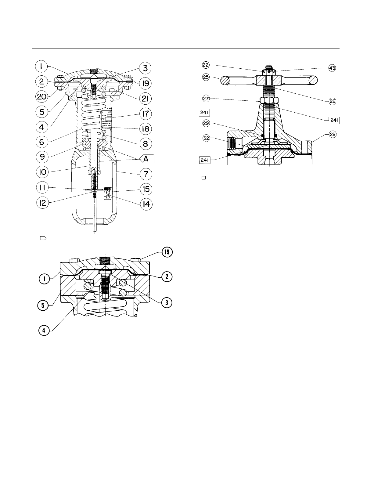
APPLY LUB
PART NOT SHOWN : 31
28A1216-C/DOC
Figure 5. Size 3A and 4A Top-Mounted
Handwheel Assembly
30A8341-A/DOC
A
APPLY MOLY-GREASE LUBRICANT TO ADJUSTING SCREW
SIZE 3A AND 4A ACTUATOR DIAPHRAGM CASINGS
30A8342-A/DOC
Figure 4. Type 655 Actuator
Key Description Part Number
9 Lower Spring Seat
10 Adjusting Screw
11 Travel Indicator Disk
12 Hex Nut
13 Travel Stop
14 Screw
15 Travel Indicator Scale
16 Twin Speed Nut
17 Nameplate
Key Description Part Number
18 Drive Screw
19 Cap Screw
20 Hex Nut
21 Cap Screw
Top-Mounted Handwheel
Sizes 3A, 4A, 3B & 4B
22 Hex Jam Nut
24 Washer
25 Handwheel
26 Handwheel Stem
27 Hex Jam Nut
28 Handwheel Body
29* O-Ring, nitrile 1D237506992
30* O-Ring, nitrile (not shown) Sizes 3B & 4B only 1D267306992
31 Groove Pin
32 Pusher Plate
33 Cap Screw
34 Travel Stop
Sizes 32 thru 46
51 Handwheel
54 Hex Nut
133 Handwheel Stem
134 Washer
135 Pusher
137 Hex Nut
138* O-Ring, nitrile 1D237506992
139* O-Ring, nitrile 1D267306992
140 Groove Pin
141 Cap Screw
142 Handwheel Body
241 Lithium grease lubricant-1, 0.396 kg (14 oz.) can
(not furnished with actuator)
*Recommended spare parts
13
Page 14
655 and 655R Actuators
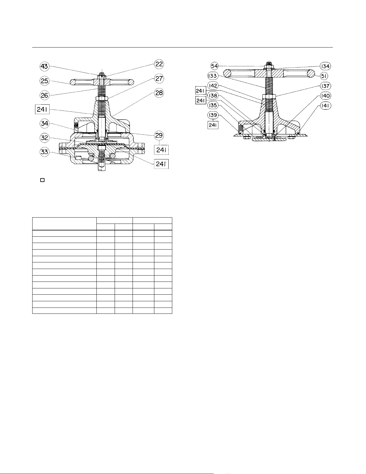
APPLY LUB
PARTS NOT SHOWN : 30 & 31
38A1217-B/DOC
Figure 6. Size 3B and 4B Top-Mounted
Key 6 Spring, steel
COLOR CODE
Aluminum & red 22 123 1290 290
Aluminum & dark green 43 246 2420 545
Dark green 64 368 3750 843
Aluminum 86 490 4720 1060
Dark blue 107 612 5200 1187
Aluminum & dark blue 145 830 7250 1630
Light blue 220 1260 8184 1840
Light green 257 1470 9790 2200
Light grey 310 1770 11,600 2600
Yellow 368 2100 13,500 3045
Dark grey 129 735 5160 1160
Aluminum & brown 175 1000 7000 1575
White 441 2520 14,010 3150
Handwheel Assembly
SPRING RATE SAFE LOAD
N/mm Lb/in. N Lb
Instruction Manual
Form 1292
July 2007
BV8008-E/DOC
Figure 7. Size 32 through 46 Top-Mounted Handwheel
Assembly.
14
Page 15

Instruction Manual
Form 1292
July 2007
655 and 655R Actuators
15
Page 16

655 and 655R Actuators
Instruction Manual
Form 1292
July 2007
Fisher is a mark owned by Fisher Controls International LLC, a member of the Emerson Process Management business division of Emerson
Electric Co. Emerson Process Management, Emerson, and the Emerson logo are trademarks and service marks of Emerson Electric Co.
All other marks are the property of their respective owners.
The contents of this publication are presented for informational purposes only, and while every effort has been made to ensure their accuracy, they are
not to be construed as warranties or guarantees, express or implied, regarding the products or services described herein or their use or applicability.
We reserve the right to modify or improve the designs or specifications of such products at any time without notice.
Neither Emerson, Emerson Process Management, nor any of their affiliated entities assumes responsibility for the selection, use and
maintenance of any product. Responsibility for the selection, use and maintenance of any product remains with the purchaser and end-user.
Emerson Process Management
Marshalltown, Iowa 50158 USA
Cernay 68700 France
Sao Paulo 05424 Brazil
Singapore 128461
www.Fisher.com
16
EFisher Controls International LLC 1975, 2007; All Rights Reserved Printed in USA
 Loading...