

Page 1
Instruction Manual
D200129X012
2506/2516 Receiver/Controller
Fisher™ 2506 and 2516 Receiver/Controllers
June 2017
Contents
Introduction 2.................................
Scope of Manual 2.............................
Description 2.................................
Specifications 2...............................
Educational Services 4.........................
Installation 5..................................
Mounting the Controller 5......................
Actuator Yoke Mounting 6..................
Wall Mounting 6...........................
Actuator Diaphragm Case Mounting 7........
Pipestand Mounting 8......................
2500 Controller/Transmitter and
2506/2516 Receiver/Controller Mounting 9.
Connections 11...............................
Supply Connection 12......................
Output Connections 12.....................
Instrument Connection 12..................
Vents 12.................................
Remote Set Point Connection 13.............
Startup 13.....................................
Adjustments 14................................
Set Point Adjustment 14........................
Remote Set Point Adjustment 15................
Proportional Band Adjustment 15................
Reset Adjustment
(2516 Receiver/Controller Only) 15............
Anti‐Reset Windup Valve Adjustment
(2516F Receiver/Controller Only) 15...........
Calibration 16..................................
Principle of Operation 17........................
2506 Receiver/Controllers 17...................
2516, 2516F Receiver/Controllers 18.............
Maintenance 19................................
Changing Controller Action 19..................
Troubleshooting 20............................
Testing Relay Deadband 21.....................
Replacing Receiver/Controller Parts 21............
Bellows Replacement 21....................
Changing the Relay 22......................
Changing Proportional or Reset Valve 22......
Parts Ordering 22...............................
Parts Kits 23...................................
Parts List 23...................................
Receiver/Controller Common Parts 23............
Anti‐Reset Windup Valve for 2516F Only 26.......
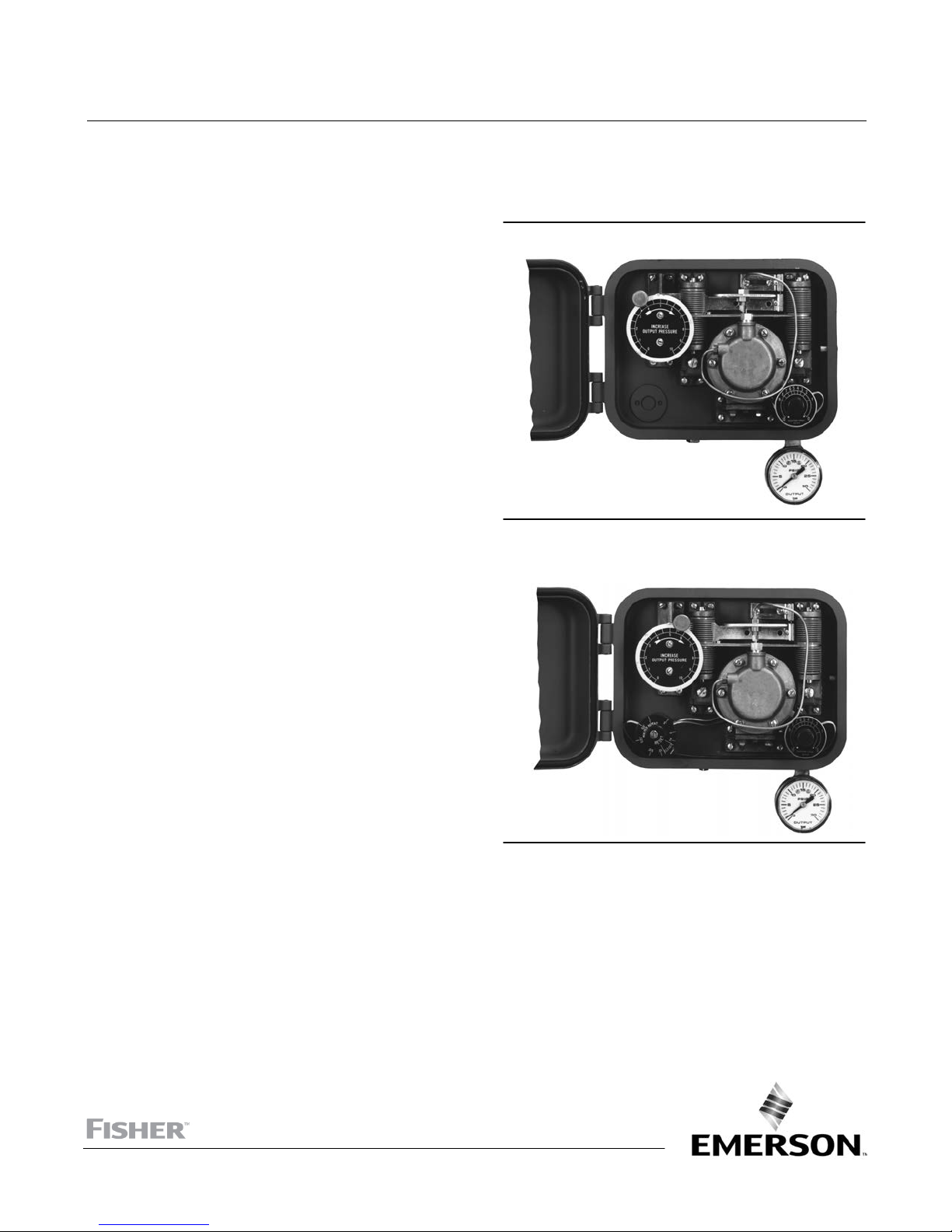
Figure 1. Fisher 2506 Receiver‐Controller
W4687
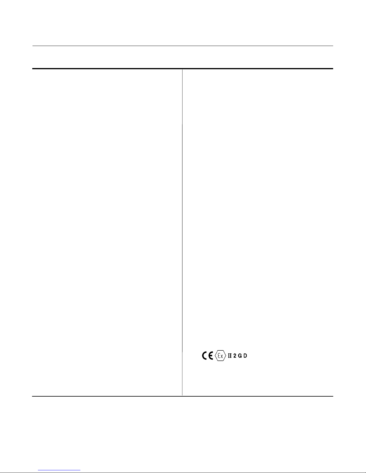
Figure 2. Fisher 2516 Receiver‐Controller
W4688
2516F Reset and Anti‐Reset Windup
Valve Assembly 26..........................
Mounting Parts 27.............................
Yoke Mounting 27.........................
Wall Mounting 27..........................
Case Mounting 27.........................
Pipestand Mounting 27.....................
2500 Controller/Transmitter and 2506/2516
Receiver/Controller Mounting 27..........
www.Fisher.com
Page 2

2506/2516 Receiver/Controller
June 2017
Instruction Manual
D200129X012
Introduction
Scope of Manual
This manual provides installation, startup, calibration, maintenance, and parts ordering information for 2506 and
2516 receiver/controllers. Figure 1 shows a 2506 receiver/controller. Figure 2 shows a 2516 receiver/controller.
A 2506/2516 receiver/controller is often used with a 2502 controller/transmitter. For information about 2502
controller/transmitters or associated equipment such as pressure regulators, sensors, accessories, or related control
devices, see the appropriate instruction manual, or contact your Emerson sales office
Do not install, operate, or maintain a 2506/2516 receiver/controller without being fully trained and qualified in valve,
actuator, and accessory installation, operation, and maintenance. To avoid personal injury or property damage, it is
important to carefully read, understand, and follow all contents of this quick start guide, including all safety cautions
and warnings. If you have any questions about these instructions, contact your Emerson sales office or Local Business
Partner before proceeding.
or Local Business Partner.
Description
See table 2.
The receiver/controllers described in this manual provide:
D Proportional‐only control: 2506 (with snap action: 2506S)
D Proportional‐plus‐reset control (2516)
D Proportional‐plus‐reset‐plus‐anti‐reset windup control (2516F)
See figures 9, 10, and 11.
The receiver/controller takes a pneumatic input signal from either a 2500 controller/transmitter or a control device.
The unit then provides a pneumatic output signal that operates a final control element.
When a 2506 receiver/controller is used to provide proportional‐only control, the pneumatic output signal from the
unit can also be piped to a remote receiving indicator or recording device. This provides a visual indication of
receiver/controller action.
The INCREASE OUTPUT PRESSURE adjustment is used to increase or decrease the output pressure in relationship to the
input pressure. Changing this adjustment changes the position of the nozzle in relationship to the beam/flapper
assembly. In turn, the amount of supply pressure released by the relay is changed and the pneumatic output signal
that operates a final control element is affected.
If a remote set point signal is used, it is piped to the remote set point connection and into remote set point bellows.
The remote signal expands the bellows and moves the beam/flapper assembly. This affects the controller output in the
same way a change in the INCREASE OUTPUT PRESSURE adjustment affects the output.
Specifications
Specifications are shown in table 1.
2
Page 3
Instruction Manual
D200129X012
Table 1. Specifications
2506/2516 Receiver/Controller
June 2017
Available Configurations
For additional information, refer to table 2
(1)
2506: A receiver/controller
that is set for either
proportional or snap action (S) control or for either
direct or reverse (R) action
2516: A 2506 that also provides proportional‐plusreset control
2516F: A 2516 that also provides anti‐reset windup
control
Input Signal Range
From a transmitter or control device, a signal of 0.2 to
1.0 bar (3 to 15 psig) or 0.4 to 2.0 bar (6 to 30 psig) is
required depending on receiver/controller range
Refer to the receiver/controller nameplate for specific
range.
Output Signal Range
(2)
See table 3
Output Action
Direct Action: An increasing fluid, interface level, or
density increases output pressure or,
Reverse Action: An increasing fluid, interface level, or
density decreases output pressure
Supply Medium
Air or Natural Gas
Supply medium must be clean, dry, and noncorrosive
Per ISA Standard 7.0.01
A maximum 40 micrometer particle size in the air
system is acceptable. Further filtration down to 5
micrometer particle size is recommended. Lubricant
content is not to exceed 1 ppm weight (w/w) or
volume (v/v) basis. Condensation in the air supply
should be minimized
Per ISO 8573-1
Maximum particle density size: Class 7
Oil content: Class 3
Pressure Dew Point: Class 3 or at least 10_C less than
the lowest ambient temperature expected
Steady State Air Consumption
(2)
See table 3
Proportional Band Reset, and Anti‐Reset Windup
See table 2 and the Changing Controller Action
procedure
Performance
Hysteresis: 0.6 percent of output pressure change at
100 percent of proportional band for 2506
proportional receiver/controllers only
Standard Supply and Output Pressure Gauge
Indications
See table 3
Remote Set Point Signal Range
From a control device, provide a remote set point
signal that is 0.2 to 1.0 bar (3 to 15 psig) or 0.4 to 2.0
bar (6 to 30 psig) that matches the receiver/controller
input signal range
Supply Pressure
(3)
Normal Operating Pressure: See table 3
Maximum Pressure to Prevent Internal Part Rupture:
3.4 bar (50 psig)
-continued-
Standard Tubing Connections
All connections are 1/4 NPT internal
Hazardous Area Classification
2506 receiver/controllers comply with the
requirements of ATEX Group II Category 2 Gas and
Dust
Operative Ambient Temperature Limits
(3)
Standard: -40 to 71°C (-40 to 160°F)
High Temperature: -18 to 104°C (0 to 220°F)
3
Page 4

2506/2516 Receiver/Controller
June 2017
Table 1. Specifications (continued)
Instruction Manual
D200129X012
Approximate Weight
4.54 kg (10 Pounds)
4 of the PED Directive 2014/68/EU. It was designed
and manufactured in accordance with Sound
Engineering Practice (SEP) and cannot bear the CE
marking related to PED compliance.
Declaration of SEP
Fisher Controls International LLC declares this
product to be in compliance with Article 3 paragraph
NOTE: Specialized instrument terms are defined in ANSI/ISA Standard 51.1 - Process Instrument Terminology.
1. Receiver/controllers are field adjustable between direct or reverse action. If the receiver/controller is set for reverse action at the factory, an R suffix will appear in the type number. Receiver/
controllers are field‐adjustable between proportional and snap action. If the receiver/controller is set for snap action at the factory, an S suffix appears in the type number.
2. Normal m
3. The pressure/temperature limits in this document, and any applicable standard or code limitation should not be exceeded.
3
/hr at 0°C, 1.01325 bar absolute (Scfh at 60°F, 14.7 psia).
However, the product may bear the CE marking to
indicate compliance with other applicable EC
Directives.
Table 2. Additional Information
Control Mode
Proportional control (2506) Proportional Band: Adjustable from 0 to 100% of transmitter signal.
Snap action control
(2506S)
Proportional‐plus‐reset
control (2516)
Proportional‐plus‐reset
with differential relief
control (2516F)
1. Proportional control is continuously active between 0 and 100 percent of the transmitter signal span. Differential gap provides snap action between 0 and 100 percent of the transmitter
signal. Do not use reset controllers in snap action.
(1)
Snap Action: Control output is at 0 or 100% of input supply pressure. Switching depends on
position of sensor and is adjustable.
Proportional Band: Adjustable from 0 to 200% of transmitter signal. Recommended setting
is from 20 to 200%.
Reset: Adjustable form 0.01 to 74 minute per repeat with standard reset valve setting.
Proportional Band: Adjustable from 0 to 200% of transmitter signal. Recommended setting
is from 20 to 200%.
Reset: Adjustable from 0.01 to 74 minute per repeat with standard reset valve setting.
Differential Relief: Provides relief when output pressure falls or when output pressure rises
depending on valve adjustment.
Action (Full Output Change) Output Signal
0.2 to 1.0 bar (3 to 15 psig) or
0.4 to 2.0 bar (6 to 30 psig)
0 to 1.4 bar (0 to 20 psig) or
0 to 2.4 bar (0 to 35 psig)
0.2 to 1.0 bar (3 to 15 psig) or
0.4 to 2.0 bar (6 to 30 psig)
Table 3. Supply Pressure Data
OUTPUT SIGNAL RANGE
0.2 to 1.0 bar (3 to 15 psig) 0 to 30 psig 1.4 20 4.2 scfh
0.4 to 2.0 bar (6 to 30 psig) 0 to 60 psig 2.4 35 7 scfh
1. Consult your Emerson sales office for gauges calibrated in other units of measurement.
2. Control and stability may be impaired if this pressure is exceeded.
3. At zero or maximum proportional band or span setting.
4. At setting in middle of proportional band or span range.
5. If air consumption is desired in normal m
3
/hr at 0°C and 1.01325 bar, multiply scfh by 0.0268.
STANDARD SUPPLY AND
OUTPUT PRESSURE GAUGE
INDICATIONS
(1)
NORMAL OPERATING
SUPPLY PRESSURE
Bar Psig Minimum
(2)
AIR CONSUMPTION AT NORMAL
OPERATING SUPPLY PRESSURE
(3)
(5)
(5)
Maximum
27 scfh
42 scfh
Educational Services
For information on available courses for 2506 or 2516 receiver/controllers as well as a variety of other products,
contact:
Emerson Automation Solutions
Educational Services - Registration
Phone: 1-641-754-3771 or 1-800-338-8158
E-mail: education@emerson.com
emerson.com/fishervalvetraining
(4)
(5)
(5)
4
Page 5

Instruction Manual
D200129X012
2506/2516 Receiver/Controller
June 2017
Installation
WARNING
To avoid personal injury or property damage resulting from the sudden release of pressure:
D Always wear protective clothing, gloves, and eyewear when performing any installation procedures to avoid personal
injury.
D Check with your process or safety engineer for any additional measures that must be taken to protect against process
media.
D If installing into an existing application, also refer to the WARNING at the beginning of the Maintenance section in this
instruction manual.
CAUTION
Do not use sealing tape on pneumatic connections. This instrument contains small passages that may become obstructed
by detached sealing tape. Thread sealant paste should be used to seal and lubricate pneumatic threaded connections.
Mounting the Controller
Note
If a separate receiver/controller unit has been ordered for field installation with an existing valve/actuator assembly or 2500
controller/transmitter, additional mounting parts may be required. Find the mounting description in the parts list at the end of this
manual. Then, order any additional parts.
Figures 3 through 8 show dimensions and connection locations used when you install a receiver/controller.
Figure 3. Dimensions and Location of Connections
235
(9.25)
171
(6.76)
232
(9.12)
FRONT VIEW
BELLOWS VENT OR
REMOTE SET POINT
CONNECTION
OUTPUT CONNECTION
(MARKED DIAPHRAGM)
44
(1.75)
70
(2.75)
SUPPLY
CONNECTION
57
(2.25)
70
(2.75)
MOUNTING
HOLES (2 PLACES)
5/16‐18 UNC
41
(1.62)
INSTRUMENT
CONNECTION
CASE VENT
TAPPED
VENT FOR
VENT LINE
(OPTIONAL)
AD4913‐H
A3844‐1
BOTTOM VIEW
REAR VIEW
mm
(INCH)
5
Page 6

2506/2516 Receiver/Controller
June 2017
Instruction Manual
D200129X012
Actuator Yoke Mounting
See figure 4 for a typical mounting plate. Key numbers are shown in figure 5.
1. Locate the mounting plate (key 164, figure 5). Select appropriate mounting holes in the mounting plate for the
receiver/controller. Then, align the mounting holes in the mounting plate with the mounting holes in the
receiver/controller case.
2. Place the two cap screws (key 48) through the mounting plate from “back to front”. Engage the cap screw threads
in the mounting holes in the receiver/controller case and tighten the cap screws to attach the mounting plate to the
back of the receiver/controller.
3. Place cap screws (key 39) through the yoke mounting holes in the mounting plate from “front to back”. Place a
spacer (key 174) over the threads of the cap screws extending from the mounting plate to properly separate the
mounting plate and the lower yoke boss of the actuator (figure 5).
4. Attach the mounting plate with receiver/controller to the lower yoke boss of the actuator yoke. Be sure the spacers
support the mounting plate. Be sure the receiver/controller is parallel with the actuator yoke and then tighten the
cap screws into the yoke boss.
5. If supply pressure is piped through a filter/regulator, bolt the regulator directly to the upper yoke boss using the cap
screws (key 85). Provide appropriate piping from the filter/regulator output connection to the receiver/controller
supply connection.
Figure 4. Mounting Plate for Yoke Mounting, Wall
Figure 5. Yoke Mounting
Mounting
13
8 HOLES
11/16 DIAMETERS
(17)
(0.50)
35
(1.38)
IC2218‐E
83
(3.25)
57
(2.25)
(0.69)
(0.50)
38
(1.50)
17
(0.56)
13
(0.69)
14
14
(0.58)
17
102
(4.00)
mm
(INCH)
SPACER (KEY 174)
CAP SCREW AND
LOCKWASHER
(KEYS 39 AND 83)
38b39604‐A
AD44913‐H
A3848‐1
Wall Mounting
See figure 6 for key number locations. The mounting plate is shown in figure 4.
REGULATOR OUTPUT
(SUPPLY CONNECTION
ON OPPOSITE SIDE)
MOUNTING PLATE
(KEY 164)
CAP HEAD SCREW
(KEY 48)
6
Page 7

Instruction Manual
D200129X012
2506/2516 Receiver/Controller
June 2017
Figure 6. Wall Mounting
MOUNTING
PLATE (KEY 164)
AD4913‐H
A3847‐1
194
(7.62)
SIDE VIEW
SPACER
(KEY 78)
CAP SCREW AND
LOCKWASHER
(KEYS 39 AND 83)
SPACER (KEY 174)
mm
(INCH)
1. Install lock washers (key 83) on the cap screws (key 39). Then, insert the cap screws through the mounting plate
from “back to front”. Place a spacer (key 174) over the threads of each cap screw as it extends from the mounting
plate. The spacers are required to properly separate the receiver/controller from the mounting plate. Then, thread
the cap screws into the mounting holes in the receiver/controller case and tighten.
2. Install lock washers (key 83) on the cap screws (key 48). Then, insert the cap screws through the mounting plate
from “front to back”. Place a spacer (key 174) over the threads of each cap screw as it extends from the mounting
plate. The spacers are required to properly separate the mounting plate from the wall mounting position. Then,
thread the cap screws into holes prepared at the wall mounting position and tighten.
3. Provide appropriate piping from the filter/regulator output connection to the receiver/controller supply
connection.
Actuator Diaphragm Case Mounting
To mount a receiver/controller to the diaphragm casing of a standard diaphragm actuator, remove two hex nuts and
hex head cap screws securing the upper and lower diaphragm casings. If necessary, refer to the appropriate actuator
instruction manual to locate the hex head cap screws and nuts.
See figure 7 for key number locations.
Figure 7. Case Mounting
CAP HEAD SCREW
(KEY 39)
CAP HEAD
SCREW
(KEY 48)
mm
(INCH)
MOUNTING
BRACKET
(KEY 164)
AD4913‐H
A3846‐1
121
(4.75)
86
(3.38)
7
Page 8

2506/2516 Receiver/Controller
June 2017
Instruction Manual
D200129X012
1. Locate the receiver/controller mounting holes in mounting bracket (key 164, figure 7).
2. Place the two cap screws (key 48) through the receiver/controller mounting plate holes from “back to front''.
Engage the threads in the receiver/controller mounting holes and tighten the cap screws to attach the mounting
plate to the back of the receiver/controller.
3. Locate the receiver/controller mounting position on the horizontal edge of the diaphragm case. A typical Fisher
diaphragm actuator features upper and lower diaphragm casings held together with hex head cap screws and hex
nuts. Remove the hex nuts from two hex head cap screws joining the upper and lower casing. Then, remove the cap
screws.
4. Engage the cap screw threads in the mounting holes in the receiver/controller case and tighten the cap screws to
attach the mounting plate to the back of the receiver/controller.
5. Place the mounting bracket over the empty casing holes. Insert the casing cap screws through the mounting
bracket, upper casing, and lower casing. Add the nuts and tighten to secure the mounting bracket with
receiver/controller to the casing.
6. If supply pressure is piped through a filter/regulator, the regulator may be attached in one of two locations:
D Attach the regulator directly to the upper yoke boss using the cap screws (key 85) for yoke mounting.
D Attach the regulator to the casing using a mounting bracket (key 177). The mounting bracket for the regulator is
the same as the mounting bracket for the receiver/controller. Follow steps 1 through 4 to mount the regulator.
7. Connect the filter/regulator output connection to the receiver/controller supply connection.
Pipestand Mounting
See figure 8 for key number locations.
Figure 8. Pipestand Mounting
MOUNTING PLATE
2
NOTES:
1 PIPE CLAMP INCLUDES NUTS
2 FILTER/REGULATOR MOUNTING AREA
AD4913‐H
A3845‐1
1. Locate the mounting plate (key 164). Select appropriate mounting holes in the mounting plate for the
receiver/controller. Then, align the mounting holes in the mounting plate with the mounting holes in the
receiver/controller case.
2. Place the two cap screws (key 48) through the mounting plate from “back to front”. Place a spacer (key 174) over
the threads of each cap screw as it extends from the mounting plate. The spacers are required to properly separate
the receiver/controller from the mounting plate.
(KEY 164)
SPACE SPOOL
(KEY 78)
157
(61.9)
CAP SCREW AND LOCKWASHER
(KEYS 39 AND 83)
PIPE CLAMP
(KEY 175)
51 j PIPE
(2.00)
1
mm
(INCH)
8
Page 9
Instruction Manual
D200129X012
2506/2516 Receiver/Controller
June 2017
3. Attach the mounting plate with receiver/controller to a 2‐inch (nominal) pipe with pipe clamps (key 175). Each pipe
clamp includes two nuts. Tighten clamp nuts.
4. If supply pressure is piped through a filter/regulator, the regulator may be attached to the mounting plate using cap
screws (key 85), lock washers (key 84), and hex nuts (key 40).
5. Provide appropriate piping from the filter/regulator output connection to the receiver/controller supply
connection.
2500 Controller/Transmitter and 2506/2516 Receiver/Controller Mounting
If the controller/transmitter and receiver/controller are ordered simultaneously, the factory will mount them together
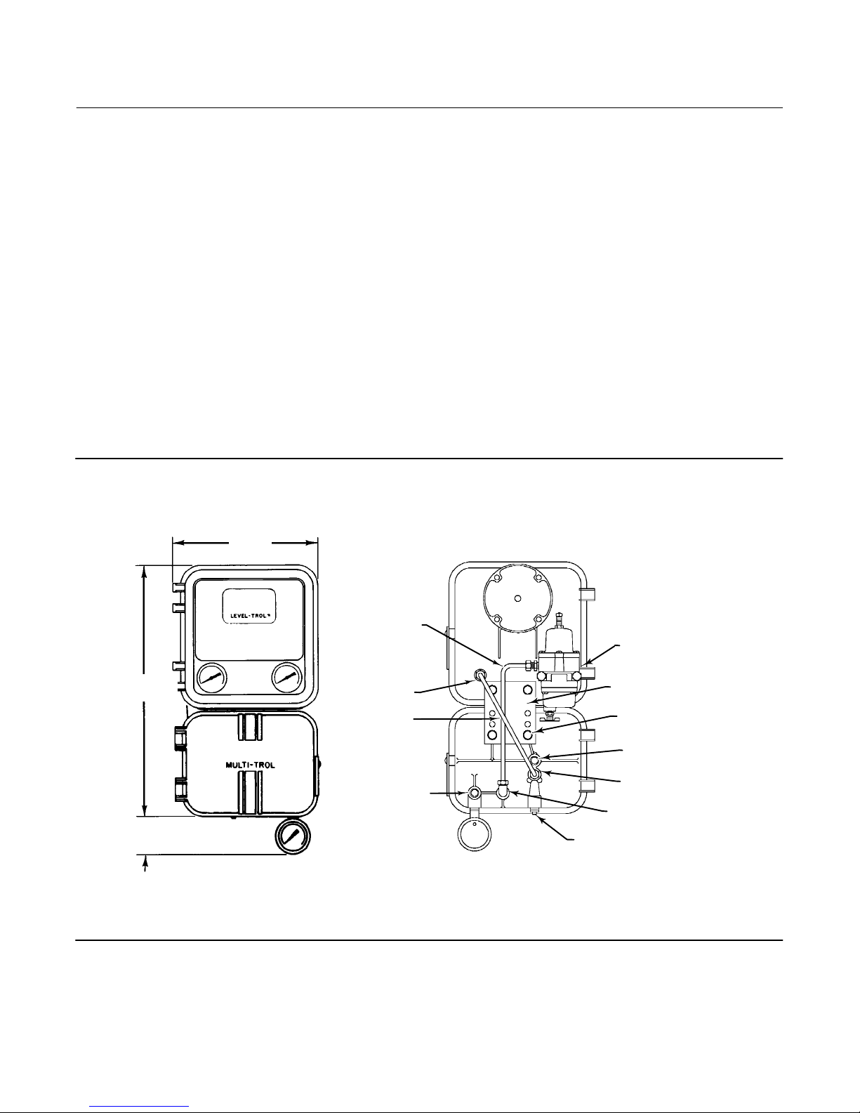
before shipment (figure 9). For examples of typical transmitter/receiver mounting arrangements, see figures 10
and 11.
If the receiver/controller is ordered separately for use with a 2500 controller/transmitter, it may not have the required
mounting parts. If mounting parts are required, consult the parts list under the specific mounting application.
See figure 9 for key number locations.
Figure 9. Fisher 2500 Controller‐Transmitter and 2506/2516 Receiver‐Controller Mounting
AR5748‐B
3V7594‐B
B2115‐1
406
(16.00)
60
(2.37)
235
(9.25)
FRONT VIEW
TUBING
(KEY 169)
TRANSMITTER
OUTPUT
TUBING
(KEY 168)
OUTPUT
CONNECTION
(MARKED
DIAPHRAGM)
REAR VIEW
1/4 NPT SUPPLY
(ON REGULATOR)
MOUNTING PLATE (KEY 164)
CAP SCREW AND LOCKWASHER
(KEYS 39 AND 83)
BELLOW VENTS OR REMOTE
SETPOINT CONNECTION
INSTRUMENT INPUT
CONNECTION
SUPPLY CONNECTION
1/4 NPT REMOTE
LEVEL INDICATOR
mm
(INCH)
1. Install lock washers (key 83) on the cap screws (key 39). Then, insert the cap screws through the mounting plate
from “back to front”. Thread the cap screws into the mounting holes in the receiver/controller case and tighten.
9
Page 10

2506/2516 Receiver/Controller
June 2017
Instruction Manual
D200129X012
2. Install lock washers (key 83) on the cap screws (key 48). Then, insert the cap screws through the mounting plate
from “back to front”. Thread the cap screws into the mounting holes in the controller/transmitter.
3. If supply pressure is piped through a filter/regulator, bolt the regulator to the back of the controller/transmitter.
4. Provide appropriate piping connections between the units as shown in figures 10 or 11.
Figure 10. Typical Transmitter with Receiver and Control Valve Installation Assembly
NOTE:
1 SEE FIGURE 9 FOR REAR VIEW
DF5357‐A
A3701‐2
SUPPLY
2500 CONTROLLER/
TRANSMITTER
2506/2516 RECEIVER/
CONTROLLER
FROM DIAPHRAGM
CONNECTION TO
ACTUATOR
DIAPHRAGM
ACTUATOR
CONTROL VALVE
1
1
1
10
Page 11

Instruction Manual
D200129X012
2506/2516 Receiver/Controller
Figure 11. Typical Transmitter and Receiver Installation with an Indicator and Remote Set Point Connection
June 2017
CONTROLLER/
TRANSMITTER
SUPPLY
4
CONTROLLER SUPPLY
NOTES:
1 PIPING FROM TRANSMITTER OUTPUT TO PANEL INDICATOR
2 PIPING FROM TRANSMITTER OUTPUT TO PANEL RECEIVER/CONTROLLER INSTRUMENT INPUT. SEE FIGURE 3 FOR CONNECTION LOCATION
3 PIPING FROM PANEL LOADER TO RECEIVER/CONTROLLER REMOTE SET POINT CONNECTION. SEE FIGURE 3 FOR CONNECTION LOCATION.
4 SEE FIGURE 3 FOR CONNECTION LOCATION.
DF5379‐A
A3702‐2
RECEIVER/
2500
CONTROLLER/
TRANSMITTER
2
INDICATOR
1
PANEL
LOADER
REMOTE
SET POINT
ADJUSTMENT
SUPPLY
CENTRALIZED
CONTROL PANEL
3
CONTROLLER OUTPUT PIPING
2506/2516 REMOTE
RECEIVER/CONTROLLER
DIAPHRAGM ACTUATOR
CONTROL VALVE
4
Connections
WARNING
The controller is capable of providing full supply pressure to connected equipment. To avoid personal injury or property
damage caused by parts bursting from system overpressure, make sure the supply pressure never exceeds the maximum
safe working pressure of any connected equipment.
CAUTION
Do not use sealing tape on pneumatic connections. This instrument contains small passages that may become obstructed
by detached sealing tape. Thread sealant paste should be used to seal and lubricate pneumatic threaded connections.
To complete the installation of a receiver/controller, make connections with tubing and fittings between the
receiver/controller and the actuator. The fittings, tubing, and mounting parts required depend on the type number
and optional equipment such as filter, regulator, and bypass valve.
11
Page 12

2506/2516 Receiver/Controller
June 2017
Instruction Manual
D200129X012
All pressure connections on 2506/2516 receiver/controllers are 1/4 NPT internal fittings (figures 3 and 9). Use 1/4‐inch
piping or 3/8‐inch tubing to these connections.
If remote venting is required, see the Vents subsection below.
Supply Connection
WARNING
Severe personal injury or property damage may occur if the instrument air supply is not clean, dry and oil free or
non‐corrosive gas. While use and regular maintenance of a filter that remove particles larger than 40 micrometers in
diameter will suffice in most applications, check with an Emerson Automation Solutions field office and industry
instrument air quality standards for use with corrosive gas or if you are unsure about the proper amount or method of air
filtration or filter maintenance.
If the existing supply is corrosive, make sure the tubing and instrument components that contact the corrosive medium are
of suitable corrosion‐resistant materials, or change to a noncorrosive supply medium.
WARNING
Personal injury or property damage may occur from bursting parts due to overpressuring any system component. To avoid
injury or damage, provide pressure‐relieving or pressure‐limiting devices if supply or input pressure could exceed the
maximum allowable pressures listed in table 3.
It is recommended that supply pressure pass through a filter/regulator combination such as a Fisher 67CFR. See table 3
for recommended supply pressures to the receiver/controller.
Typical supply pressure for the 67CFR is clean dry air or a gas at a pressure of 2.5 bar (35 psig) to a maximum of 17 bar
(250 psig). For specific regulator limits, see the appropriate regulator instruction manual.
Output Connections
See figure 3.
Use 3/8‐inch tubing between the actuator and the receiver/controller. Connect the output (diaphragm) connection to
the appropriate actuator connection.
Instrument Connection
See figure 3.
Use 3/8‐inch tubing to connect the output from the control device to the INSTRUMENT connection on the
receiver/controller.
Vents
WARNING
If a flammable or hazardous gas is used as supply pressure medium, personal injury or property damage could result from
fire or explosion caused by the accumulated gas. Injury or property damage could also result from contact with flammable
12
Page 13

Instruction Manual
D200129X012
or hazardous gas. The case and cover assembly does not form a gas‐tight seal and flammable or hazardous gas could leak
from this unit. Therefore, if the receiver/controller unit is enclosed, install a remote vent line to remove part of the exhaust
gas to a properly ventilated area. However, a remote vent line cannot be relied upon to remove all hazardous gas. Vent line
piping should comply with local and regional codes and should be as short as possible. Select vent line piping with
adequate inside diameter and install with few bends to reduce case pressure buildup.
2506/2516 Receiver/Controller
June 2017
See figure 3 for vent locations.
A receiver/controller may be ordered with one of two vent configurations:
D Standard, with 1/4‐inch case vent open. The standard receiver/controller case (key 1) is not drilled and tapped for
the optional tapped vent.
D Optional, with tapped vent, for applications requiring vent line attachment to receiver/controller case. The optional
receiver/controller case features a tapped vent for applications requiring a remote vent line. The standard case vent
should be sealed with a machine screw.
An air vent plug (key 137) with gasket (key 138) and hex nut (key 139) can be added to the tapped vent. The air vent
plug provides a 1/4 NPT internal fitting.
D Receiver/controllers feature an open bellows vent/remote set point connection. An external vent assembly (key
128) is recommended if the remote set point connection is not made. The external vent assembly can be driven
into the open bellows vent.
Protect all vents against the entrance of any foreign material that could plug them. Check the vents periodically to be
certain they are not plugged.
Remote Set Point Connection
WARNING
Severe personal injury or property damage may occur if the instrument air supply is not clean, dry and oil free or
non‐corrosive gas. While use and regular maintenance of a filter that remove particles larger than 40 micrometers in
diameter will suffice in most applications, check with an Emerson Automation Solutions field office and industry
instrument air quality standards for use with corrosive gas or if you are unsure about the proper amount or method of air
filtration or filter maintenance.
See figure 3.
The remote set point connection is made at the tapped bellows vent/remote set point connection on the rear of the
receiver/controller case. A vent assembly (key 128) is recommended if the remote set point connection is not made.
To make a remote set point connection, remove the vent assembly from the connection. Install piping from the
remote set point loader or regulator.
When a panel loader or regulator is used for remote set point adjustment, as shown in figure 11, an adjustable output
range of 0.2 to 1 bar (3 to 15 psig) or 0.4 to 2 bar (6 to 30) is required to match the receiver/controller output range.
Use clean, dry air or a non‐corrosive gas for supply pressure to the remote set point bellows.
Startup
It is important that the output range of the transmitter or other device used as the input to the receiver/controller be
adjusted so that its output range corresponds to the input signal range of the receiver/controller. Be sure the
receiver/controller action (direct or reverse) is correct for the application.
13
Page 14

2506/2516 Receiver/Controller
June 2017
To start the system:
D For all receiver/controllers, perform steps 1 and 2.
1. See table 3 for specific pressure limits. Be sure the correct supply pressure is available. If necessary, adjust the
regulator to 1.4 bar (20 psig) for a 0.2 to 1 bar (3 to 15 psig) or 2.4 bar (35 psig) for a 0.4 to 2 bar (6 to 30 psig)
receiver/controller range.
2. Turn on the supply pressure to the receiver/controller.
D To make the proper level or output pressure setting for a 2506 receiver/controller, go to step 3. To make the proper
level or output pressure setting for a 2516 receiver/controller, go to step 9.
D For the 2506 receiver/controller:
3. Set the proportional band adjustment at 15 percent (1.5 on the adjustment dial). At this setting, a 0.1 bar (1.8 psig)
input pressure causes a 12 psig output pressure change. Operate the receiver/controller with the proportional band
setting as small as possible.
4. Provide an input pressure equal to the output pressure of the transmitter at a value desired or halfway between the
transmitter output range. For example, on a receiver/controller, if the desired control point is halfway between the
ends of the displacer, provide an input of 0.6 bar (9 psig) which is halfway between 0.2 and 1 bar (3 and 15 psig)
transmitter output range.
5. Set the output pressure adjustment to give a controller output that is halfway between its output range.
6. Vary the input pressure to be sure the full controller output pressure range is produced within the specified input
pressure range.
7. Lock the output pressure adjustment and connect the receiver/controller to the final control element.
8. If the proportional band setting is too narrow, causing instability, widen the proportional band just enough to
stabilize control. After making this adjustment, it may be necessary to reset the output pressure slightly to produce
the proper control range.
Instruction Manual
D200129X012
D For the 2516 receiver/controller:
9. Set the proportional band adjustment dial at 0 percent (minimum proportional band).
10. Set the reset adjustment to the fastest speed (0.005 minutes‐per‐repeat).
11. Provide an input pressure equal to the output pressure of the transmitter at a value desired or halfway between the
transmitter output range. For example, on a receiver/controller, if the desired control point is halfway between the
ends of the displacer, provide an input of 0.6 bar (9 psig) which is halfway between 0.2 and 1 bar (3 and 15 psig)
transmitter output range.
12. Adjust the output pressure dial to give a controller output somewhere within the output range of the
receiver/controller.
13. Lock the output pressure dial and connect to the final control element.
14. If the proportional band is too narrow causing instability, widen the proportional band or slow the reset just enough
to stabilize control.
Adjustments
To adjust the receiver/controller, open the cover and locate the appropriate adjustment. See figures 14, 15, and 16 for
the location of adjustments.
Set Point Adjustment
To adjust the level set point, loosen the knurled knob and rotate the knob around the INCREASE OUTPUT PRESSURE or
RAISE LEVEL dial. To raise fluid or interface level or increase density, rotate the knob in the direction of the arrow.
14
Page 15

Instruction Manual
D200129X012
To lower level or decrease density, rotate the knob in the opposite direction. The INCREASE OUTPUT PRESSURE or
RAISE LEVEL dial is graduated (in percent) to show approximate indications of the receiver/controller set point. When
making adjustments, do not rely only on the dial setting. Monitor the process fluid level to be sure the
receiver/controller attains the desired set point.
For differential gap receiver/controllers, the level setting adjustment determines the location of the gap within the
range of the sensing element.
2506/2516 Receiver/Controller
June 2017
Remote Set Point Adjustment
On a receiver/controller with remote set point adjustment capability, adjust the set point by changing the pressure to
the remote set point connection. Increase the remote set point signal pressure to decrease the receiver/controller set
point (for a direct acting receiver/controller) or increase the receiver/controller set point (for a reverse acting
receiver/controller).
Proportional Band Adjustment
For proportional and proportional‐plus‐reset receiver/controllers, the proportional band adjustment determines the
amount of change in the input pressure required to change the controller output signal from one limit of the output
signal range to the other limit (without the effect of reset action).
Proportional band is expressed as a percent of the sensing element range. That is, with a proportional band of 100
percent, an input pressure change equal to the sensing element span would change the controller output from one
limit to the other. With a proportional band of 50 percent, an input pressure change equal to one half the sensing
element range would change the controller output from one limit to the other.
The proportional valve dial is graduated from 0 to 10. A setting of 10 on the dial represents a proportional band of 100
percent; 5 represents a proportional band of 50 percent.
The receiver/controller is designed for a maximum proportional band of 200 percent. The effective band is determined
by the location of the adjustable nozzle assembly (key 17, figure 14) in the slot in the level set arm (key 28). Most
applications require a maximum band of 100 percent so, at the factory, a receiver/controller unit is set to the 100
percent value. This setting places the nozzle at a point that is halfway between the bellows assemblies. To adjust the
proportional band, rotate the adjustment counterclockwise to broaden the setting. Rotate the adjustment clockwise
to narrow the setting.
In some applications, a 200 percent proportional band range may be required. To obtain the 200 percent range, move
the nozzle assembly to the extreme right end of the slot in the level set arm.
For differential gap receiver/controllers, the proportional band adjustment determines the width of the differential
gap. This is the difference between the input pressures at which the controller output switches from zero to full supply
pressure and back to zero.
Reset Adjustment (2516 Receiver/Controller Only)
On proportional‐plus‐reset receiver/controllers, the reset adjustment determines the time in minutes required for the
reset action to produce a change in output pressure equal to the change that has occurred due to proportional band
action.
To adjust the reset action, rotate the adjustment clockwise to decrease, or counterclockwise to increase the minutes
per repeat. Increasing the minutes per repeat provides a slower reset action.
Anti‐Reset Windup Valve Adjustment (2516F Receiver/Controller Only)
The anti‐reset windup valve provides differential pressure relief. Its adjustment control extends from the back of the
receiver/controller case (figure 16).
15
Page 16

2506/2516 Receiver/Controller
June 2017
Instruction Manual
D200129X012
The factory sets this valve to relieve when the differential pressure between the proportional and reset bellows reaches
5 psi. To set the valve to relieve when the differential pressure is as low as 2 psig, turn the adjustment screw clockwise.
To set the valve to relieve when the differential pressure is as high as 7 psig, turn the adjustment screw
counterclockwise. The minimum differential setting yields the minimum differential set point overshoot during
startup.
Depending on the characteristics of the process, the anti‐reset windup valve can be positioned so that the arrow on
the case points to the letters RE or, to the letter P on the back of the manifold. If the arrow points to P, the valve opens
when receiver/controller output pressure rises. If the arrow points to RE, the valve opens when receiver/controller
output pressure falls.
Calibration
WARNING
The following calibration procedures require taking the controller out of service. To avoid personal injury and property
damage caused by an uncontrolled process, provide some temporary means of control for the process before taking the
receiver/controller out of service. Also refer to the Warning at the beginning of the Maintenance section.
See figure 14 for key number and adjustment locations.
When performing the following calibration procedures, open loop conditions must exist and make provisions to
monitor the output pressure. One way to obtain an open loop is to disconnect the controller output signal line and
install a pressure gauge.
Note
When calibrating a combined controller arrangement such as the 2500 with the 2506 or 2516 (figure 9), calibrate the 2500
controller/ transmitter first.
For a direct action receiver/controller:
1. Adjust the INCREASE OUTPUT PRESSURE adjustment to mid‐range on the scale.
2. Turn the proportional band adjustment to 100 percent of the scale range.
3. For the 2516 only, turn the reset valve adjustment fully clockwise.
4. Adjust the input pressure to 0.6 bar (9 psig) for a 0.2 to 1 bar (3 to 15 psig) or 1.2 bar (18 psig) for a 0.4 to 2 bar (6 to
30 psig) receiver/controller.
5. For the 2516 only, turn the reset valve adjustment fully counterclockwise (to the CLOSED position). This locks 0.6
bar (9 psig) or 1.2 bar (18 psig) in the reset bellows.
6. If the output pressure is 0.6 bar (9 psig) for a 0.2 to 1 bar (3 to 15 psig) or 1.2 bar (18 psig) for a 0.4 to 2 bar (6 to 30
psig) receiver/controller, go to step 8. If not, continue with step 7.
7. If the output pressure span is too low, move the nozzle down towards the flapper, if output pressure is too high,
move the nozzle up. Continue by trial and error until the desired setting is obtained.
8. Adjust the input pressure to 1 bar (15 psig) for a 0.2 to 1 bar (3 to 15 psig) or 2 bar (30 psig) for a 0.4 to 2 bar (6 to
30 psig) receiver/controller.
16
Page 17
Instruction Manual
D200129X012
2506/2516 Receiver/Controller
June 2017
9. The output pressure should be 1 bar (15 psig) for a 0.2 to 1 bar (3 to 15 psig) or 2 bar (30 psig) for a 0.4 to 2 bar (6 to
30 psig) receiver/controller. If output pressure is within application tolerance, proceed to step 12. If not, continue
with step 10.
10. If the output pressure span is narrow, move the nozzle slightly to the left or, if the output pressure span is too wide,
move it to the right and repeat steps 4 and 6 through 10.
11. Repeat the steps until the receiver/controller is within application requirements.
12. Reconnect the receiver/controller to the control loop and see the Adjustment section.
Principle of Operation
The 2506/2516 uses a basic pressure balance relay system. The relay is connected so that supply pressure is fed to the
inlet side of the relay valve and the fixed restriction. From this restriction, the air pressure bleeds into the relay
chamber on one side of the large diaphragm and also to the nozzle. As long as there is no pressure change on either
diaphragm, the relay valve remains in equilibrium with both inlet and exhaust ends closed. The area ratio of the large
diaphragm to the small diaphragm is 3 to 1. A 12 psi pressure change on the small diaphragm is balanced by a 4 psi
change in the large diaphragm.
The following descriptions show how the relay works with the standard proportional, proportional‐plus‐reset, and
proportional‐plus‐reset with anti‐reset windup receiver/controllers.
2506 Receiver/Controllers
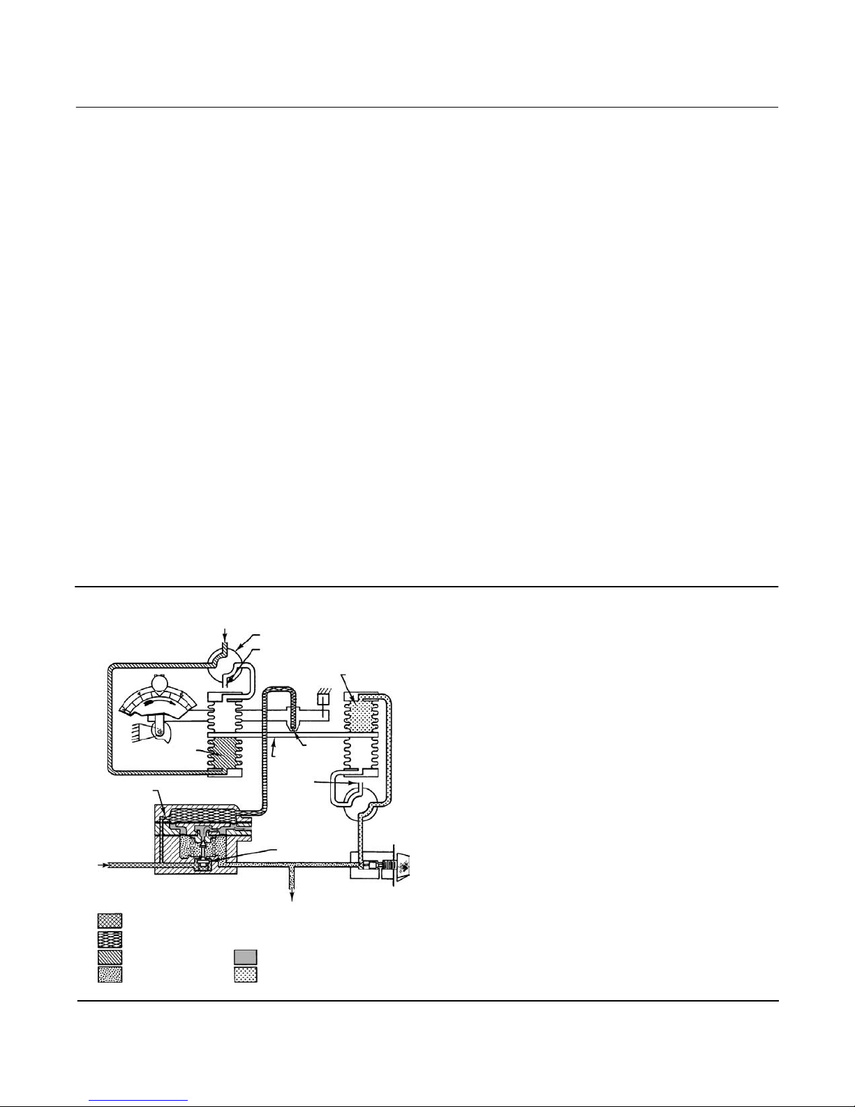
See figure 12.
Figure 12. Fisher 2506 Direct Action Receiver / Controller Schematic
SENSING BELLOWS
RESTRICTION
SUPPLY
SUPPLY PRESSURE
RELAY LOADING PRESSURE
TRANSMITTER INPUT
OUTPUT PRESSURE
BD2388‐F
A3849
TRANSMITTER INPUT
REVERSING SWITCH
BELLOWS VENT OR REMOTE SETPOINT CONNECTION
PROPORTIONAL BELLOWS
NOZZLE
BEAM/FLAPPER
ASSEMBLY
VENT
RELAY INNER
VALVE
OUTPUT PRESSURE TO
CONTROL VALVE
RELAY BLEED PRESSURE
PROPORTIONAL PRESSURE
17
Page 18

2506/2516 Receiver/Controller
June 2017
Instruction Manual
D200129X012
As long as the process level remains constant, the transmitter input pressure to the receiver/controller remains
constant. Inside the receiver/controller, the bellows beam/flapper assembly remains in a steady‐state position.
The position of the bellows beam allows the supply pressure to bleed through the nozzle as fast as it enters the relay
through the fixed restriction. A change in transmitter input pressure repositions the beam/flapper assembly with
respect to the nozzle.
On a direct action receiver/controller, an increase in transmitter input pressure causes a pressure increase in the
sensing bellows assembly, tending to push the beam toward the nozzle. This restricts the escape of supply pressure
through the nozzle, thus increasing the pressure on the large diaphragm in the relay. This opens the relay valve to the
supply pressure allowing an increase in output pressure to the control valve.
A decrease in transmitter input pressure decreases the pressure in the input bellows assembly by moving the beam
away from the nozzle. This allows the supply pressure to bleed through the nozzle faster than it can enter through the
fixed restriction in the relay. The relay valve opens, exhausting the output pressure which vent through the relay
exhaust port. This action decreases output pressure to the control valve.
2516, 2516F Receiver/Controllers
The action of a proportional‐plus‐reset controller (figure 13) is similar to that of a proportional controller except that
feedback from the controller output pressure is piped to a reset bellows as well as to the proportional bellows.
Figure 13. Fisher 2516 and 2516F Direct Action Receiver‐Controller Schematic
REMOTE SETPOINT
BELLOWS
SENSING BELLOWS
RESTRICTION
SUPPLY
SUPPLY PRESSURE
RELAY LOADING
PRESSURE
TRANSMITTER INPUT
B2116
TRANSMITTER INPUT
2516 RECEIVER/CONTROLLER
REVERSING SWITCH
BELLOWS VENT OR REMOTE
SETPOINT CONNECTION
BEAM/FLAPPER
ASSEMBLY
OUTPUT PRESSURE
TO CONTROL VALVE
OUTPUT PRESSURE
RELAY BLEED PRESSURE
PROPORTIONAL BELLOWS
NOZZLE
BEAM/FLAPPER
ASSEMBLY
RESET
BELLOWS
RESET BELLOWS
RESET VALVE
OUTPUT
PRESSURE
PROPORTIONAL
VALVE
PROPORTIONAL PRESSURE
RESET PRESSURE
RESET RELIEF
VALVE SPRING
RESET
VALVE
PROPORTIONAL VALVE
RELIEF VALVE
DIAPHRAGM
2516F RECEIVER/CONTROLLER
ADJUSTING
SCREW
DIFFERENTIAL
RELIEF VALVE
You can adjust the reset valve on the 2516 and 2516F to channel some or all of the proportional pressure into the reset
bellows that opposes the proportional bellows action. This arrangement automatically reduces the effect of any
proportional overcorrection by a set amount per time interval, as long as there is a deviation from the control point.
18
Page 19

Instruction Manual
D200129X012
2506/2516 Receiver/Controller
June 2017
The 2516F receiver/controller also features an anti‐reset windup valve. This valve provides differential pressure relief to
prevent proportional pressure from exceeding reset pressure by more than a set value. The proportional valve output
pressure registers on one side of the diaphragm chamber and the reset valve output pressure registers on the other
side diaphragm. A sudden increase in the output pressure causes a rapid pressure increase in the proportional bellows
and in the proportional side of the diaphragm chamber. If the diaphragm pressure of the relief valve exceeds that of
the spring side by the amount of the relief pressure setting, the relief diaphragm moves off the orifice in the
differential relief valve. This allows the pressure on the proportional side of the diaphragm to bleed into the reset
system. This action provides quick relief of excessive proportional pressure and reduces the time required by the
system to return to the control point. A user can reverse the differential relief action to relieve on decrease output
pressure.
Maintenance
Receiver/controller parts are subject to normal wear and may require inspection or replacement. The frequency of
inspection and parts replacement depends upon the severity of the service conditions. When inspection or repairs are
needed, disassemble only those parts necessary to accomplish the job.
Select the appropriate maintenance procedures and perform the appropriate steps. Each procedure requires that
supply pressure and process pressure be shut off before beginning maintenance.
Establish a maintenance cycle to regularly clean the vents (figure 3). Also, establish a maintenance cycle to clear the
relay orifice (key 88, not shown) by pushing in the plunger of the core assembly (key 89).
WARNING
The following maintenance procedures require taking the controller out of service. To avoid personal injury and property
damage caused by an uncontrolled process:
D Always wear protective clothing, gloves, and eyewear when performing any maintenance operations to avoid personal
injury.
D Provide some temporary means of controlling the process before taking the receiver/controller out of service.
D Release any trapped pressure from the controller and vent supply pressure before disassembly.
D Check with your process or safety engineer for any additional measures that must be taken to protect against process
media.
Changing Controller Action
See figure 14 for key number locations, unless otherwise directed.
Note
Do not switch the 2516 receiver/controller to snap (S) action.
To change controller action, reposition one or both switch plates (key 132), which are mounted on the left or right
bellows assemblies (key 134 or 133 respectively). When either switch plate (key 132) is removed, the raised letters D,
R, S, and P are visible on the bellows frame located under the switch plate (figure 14).
19
Page 20

2506/2516 Receiver/Controller
June 2017
Instruction Manual
D200129X012
These letters correspond to: direct (D), reverse (R), snap (S), and proportional (P) control action. To obtain the type of
control desired, position the switch plates so that the proper letter appears in the cut‐out corner, as explained below:
D The bellows assembly on the left provides either direct or reverse action. The receiver/controller (2506 or 2516) can
be changed between direct and reverse action by repositioning the switch plate (key 132) on the left. Direct action
(D) is when increasing transmitter input pressure increases receiver/controller output pressure. To obtain direct
action, position the switch plate so the D is visible. Reverse action (R) is when decreasing transmitter input pressure
increases receiver/controller output pressure. To obtain reverse action, position the switch plate so the R is visible.
D The bellows assembly on the right provides either proportional (P) or snap (S) action depending on the switch plate
position. For all types of receiver/controllers, to obtain proportional action, position the switch plate so the P is
visible. For 2506 receiver/controllers, to obtain snap action, position the switch plate so the S is visible.
Troubleshooting
As an aid to troubleshooting, see table 4 for a listing of some common operating faults, their probable cause, and
suggested procedures for correcting the faults.
Table 4.Troubleshooting Chart
Fault Possible Cause Check Correction
1. Process wanders or cycles
around set point.
Note: 1.2 is for the 2500 and
2506/16 combination.
2. Receiver/controller
controlling off set point or
switching point.
3. Receiver/controller cannot
obtain full output range.
1.1 Proportional band or specific
gravity adjustment incorrect, or
improperly tuned control loop.
1.2 Input signal varying to the
2506/16.
1.3 Supply pressure varying, or
incorrect supply pressure setting.
1.4 Relay malfunction. 1.4 Check for relay malfunction by
2.1 Supply pressure not set
correctly.
2.2 Leak in the receiver/controller
loop.
3.1 Supply pressure not set
correctly.
3.2 Nozzle adjustment. 3.2 Insure the nozzle is not loose. 3.2 Perform calibration procedures.
3.3 Relay malfunction. 3.3 Check for relay malfunction by
3.4 Leaking controller/transmitter
loop.
1.1 Insure that the prestartup
procedures are completed correctly.
Tune control loop.
1.2 Use a pressure gauge to monitor
input stability.
1.3 Use input pressure gauge to
monitor stability. Make sure regulator
supply pressure is within limits.
using the testing relay deadband
procedure.
2.1 Make sure regulator supply
pressure is set correctly. Make sure
regulator supply pressure is within
limits.
2.2 Use soap and water to check for
internal and external leaks.
3.1 Make sure supply pressure is set
correctly. Make sure regulator supply
pressure is within limits.
using the testing relay deadband
procedure.
3.4 Use soap and water to check for
internal and external leaks.
-continued-
1.1 If stable control cannot be attained,
and all other elements are functionally
correct, examine other possible causes
related to the controller/transmitter.
1.2 Apply stable input pressure source.
Tune the 2500 controller/transmitter.
1.3 Apply correct supply pressure. It is
recommended to use one regulator per
instrument.
1.4 Depress plunger to clean out the
fixed restriction. Replace relay using the
procedure in the maintenance section.
2.1 Reset the regulator pressure.
If the problem recurs, replace or rebuild
the regulator. Provide a regulator input
pressure within regulator limits.
2.2 Replace or repair leaking parts as
necessary.
3.1 Reset the regulator pressure.
If problem recurs, replace or rebuild the
regulator. Provide a regulator input
pressure within regulator limits.
3.3 Depress plunger to clean out the
fixed restriction. Replace relay using the
procedure in the maintenance section.
3.4 Replace or repair leaking parts as
necessary.
20
Page 21

Instruction Manual
D200129X012
2506/2516 Receiver/Controller
June 2017
Table 5.Troubleshooting Chart (continued)
Fault Possible Cause Check Correction
4. Receiver/controller remains
at full or zero output pressure.
4.1 Supply or output pressure
gauge malfunction.
4.2 Flapper adjustment. 4.2 Insure the flapper is not loose on
4.3 Relay malfunction. 4.3 Check for relay malfunction by
4.1 Insure the pressure gauges are
registering correctly.
the torque tube shaft. Insure the
flapper is centered on the nozzle.
using the testing relay deadband
procedure.
4.1 Replace pressure gauges.
Use corrective action given for section 3
of this table.
4.2 Replace or tighten flapper assembly
as necessary and/or center flapper on
nozzle.
4.3 Depress plunger to clean out the
fixed restriction. Replace relay using the
procedure in the maintenance section.
Testing Relay Deadband
1. Replace the PROPORTIONAL BAND adjustment assembly with a 1/8 NPT pipe plug according to the sections for
changing proportional, reset, or anti‐reset windup valves.
2. Turn on the supply pressure and set it to 1.4 bar or 2.4 bar (20 or 35 psig) according to supply pressure
requirements of the receiver/controllers.
3. By changing the process variable and adjusting the INCREASE OUTPUT PRESSURE control, set the output pressure
to 15 or 30 psig. While monitoring the output pressure, slowly change the process until an output pressure change
just begins. Record the value of the process variable at this detection point.
4. Change the process variable in the opposite direction until another output pressure change just begins. Again,
record the value of the process variable. If the difference between the two values (the deadband) is more than 0.2
percent of the maximum displacer length, the relay must be repaired or replaced.
5. See the relay removal and replacement procedures and, if necessary, the relay disassembly and assembly
procedures if the relay is to be repaired.
6. Turn off the supply pressure, remove the pipe plug, and install the PROPORTIONAL BAND adjustment assembly.
Replacing Receiver/Controller Parts
See figure 14 for key number locations, unless otherwise indicated.
Bellows Replacement
Use the following bellows replacement procedure to replace defective bellows or change the output signal range.
Removal
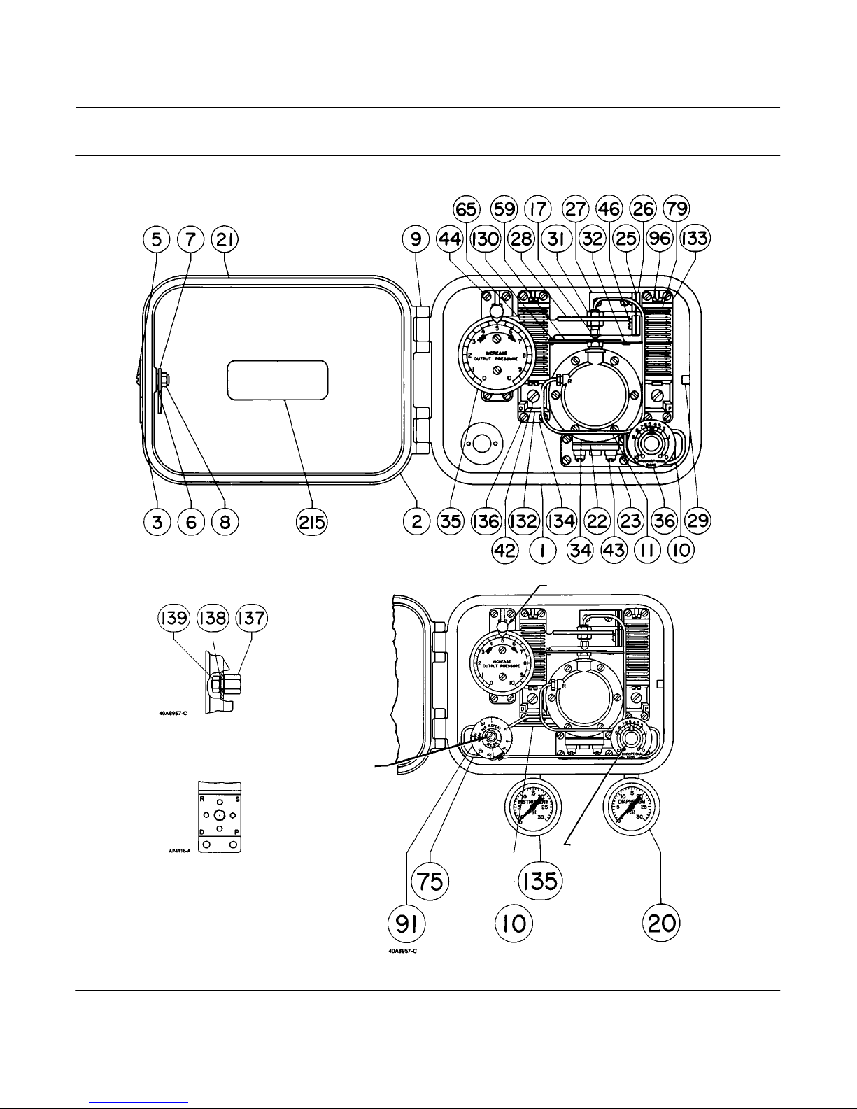
1. Remove the relay tubing assembly (key 11), the INCREASE OUTPUT PRESSURE plate (key 35), and the attached
restriction plug orifice assembly (key 11).
2. Take out the four bellows screws (key 96). These are special screws with air passages in them so, be careful not to
lose them.
3. Compress the bellows (both are key 65) slightly and slip them out of the bellows frame (keys 133 or 134).
4. Unscrew the bellows from the beam (key 59). A gasket (key 79) fits between the end of the bellows and the bellows
frame.
5. Inspect each bellows and gasket and, if necessary, replace them.
Replacement
1. First install the bellows gasket (key 79), then install each bellows (key 59) by screwing it onto the beam (key 59).
2. Compress the bellows slightly and slip them into the bellows frame (key 133 or 134).
21
Page 22

2506/2516 Receiver/Controller
June 2017
3. Secure the screws (key 96) and replace the tubing.
4. Check all tubing connections and the bellows screws for leaks. Tighten as necessary and proceed to the Calibration
section.
5. If a bellows assembly (key 65) with a different range is installed, replace the gauges (key 20 or 135) with those with
an appropriate measurement capability.
Instruction Manual
D200129X012
Changing the Relay
Remove the relay to replace it.
Removal
1. Disconnect the tubing (key 11) from the relay.
2. Remove two relay mounting screws, the relay, and the relay gasket (keys 43, 34, and 22).
Replacement
1. Install a new gasket (key 22), the replacement relay (key 34), and secure with two mounting screws (key 43).
2. Connect the tubing (key 11) to the relay.
3. See the testing relay deadband procedures in this section.
4. If the deadband is within tolerance, see the Calibration section.
Changing Proportional or Reset Valve
1. Disconnect the appropriate tubing(s) from the proportional or reset valve.
2. Removing the valve assembly:
a. Remove the proportional valve assembly by unscrewing it from the relay base. Install the replacement assembly.
b. Remove the reset valve assembly by unscrewing the two machine screws (key 182, not shown) located behind
the reset valve on the back of the case. Install the replacement assembly.
Parts Ordering
Whenever corresponding with your Emerson sales office or Local Business Partner, include the receiver/controller type
number and the serial number. The serial number can be found on the nameplate.
WARNING
Use only genuine Fisher replacement parts. Components that are not supplied by Emerson Automation Solutions should
not, under any circumstances be used in any Fisher instrument. The use of components not manufacture by Emerson
Automation Solutions may void your warranty, might adversely affect the performance of the instrument, and could cause
personal injury or property damage.
22
Page 23

Instruction Manual
D200129X012
2506/2516 Receiver/Controller
June 2017
Parts Kits
Key Description Part Number
Receiver/Controller Repair Kits
Contains keys 17, 19, 21, 24, 38, and 45
Standard Temperature R2506X00L12
High Temperature R2506X00H12
Relay Replacement Kit
Contains key 22 (43 for 2500 and 2502)
and the relay assembly (key 34)
Standard Temperature RRELAYX0L22
High Temperature RRELAYX0H22
2506/2516 Controller Cover Gasket Kit
Contains qty. 5 cover gaskets, key 21 R2506CVR012
Parts List
Note
Contact your Emerson sales office for Part Ordering information.
Key Description
1 Controller case (controller back), die cast aluminum
for 2506, 2516
Standard: W/open case vent (no optional
tapped vent for vent line)
Optional: W/tapped vent for vent line
(case vent sealed with machine screw)
Additional option: Case pressure‐tested
to 0.1 bar (2 psig). Contact your Emerson
sales office to order pressure testing.
Label (key 179) is added to the case.
1 Controller case (controller back), die cast Aluminum
for 2516F, w/open case vent (no optional
tapped vent for vent line)
2 Controller cover, die cast
3 Door handle, steel pl
4 Door handle shaft, stainless steel
(not shown)
5 Machine screw, steel pl
6 Washer, stainless steel
7 Door hook, steel pl
8 Elastic stop nut, steel pl
9 Hinge pin, stainless steel, (2 req'd)
10 Compensator tubing assembly, proportional,
stainless steel
11 Relay tubing assembly,
2506 and 2516, stainless steel
17 Orifice cap, brass
Receiver/Controller Common
Parts (figure 14)
Note
Case Vent Options:
•The standard receiver/controller case features an open case vent. The
case is not drilled for the optional tapped vent.
•All receiver/controller cases feature an open bellows vent/remote set
point connection. A external vent assembly (key 128) is recommended if
the remote set point connection is not made.
•The optional receiver/controller case features a tapped vent for
applications requiring a remote vent line. The standard case vent is
sealed w/a machine screw. An external connection (air vent plug, key
137) w/gasket (key 138) and hex nut (key 139) can be added to the
tapped vent.
Note
Gauges:
See key 135 for input (instrument) gauge or pipe plug.
20* Output (diaphragm) gauge
Triple scale
0 to 30 psig/0‐0.2 MPa/0‐2 bar
0 to 60 psig/0‐0.4 MPa/0‐4 bar
Dual scale
0 to 30 psig/0‐2 kg/cm
21* Cover gasket, chloroprene
22* Relay gasket,
Standard temperature, chloroprene
High temperature, silicone
23 Relay base, die cast zinc
24* Relay base gasket (not shown)
Standard temperature, chloroprene
High temperature, silicone rubber
25 Flexure strip, stainless steel
26 Flexure strip nut, steel (2 req'd)
27 Flexure strip base, steel
28 Level set arm, steel
29 Latch pin, steel
2
*Recommended spare parts
23
Page 24

2506/2516 Receiver/Controller
June 2017
Instruction Manual
D200129X012
Key Description
31 Nut, brass (2 req'd)
32 Flapper, K93602 nickel alloy
34 Relay assembly
Standard temperature
High temperature
35 Level adjustment assembly
35C Level adjustment dial (not shown), aluminum
Std, clockwise adjustment
Optional, counter‐clockwise adjustment
For use w/2500 controller
36 Proportional band assembly
41 Screw, steel pl (2 req'd)
42 Machine screw, steel pl (2 req'd)
43 Machine screw, steel pl (2 req'd)
44 Machine screw, steel pl (6 req'd)
46 Machine screw, stainless steel (4 req'd)
47 Spring (not shown)
56 Bellows stud, brass (2 req'd) (not shown)
59 Bellows beam, steel pl
65* Bellows assembly
Brass
Range:
0.2 to 1 bar (3 to 15 psig)
Gray color code
0.4 to 2 bar (6 to 30 psig)
Green color code
Stainless steel
Range:
0.2 to 1 bar (3 to 15 psig)
Gray color code
0.4 to 2 bar (6 to 30 psig)
Green color code
Key Description
91 Reset restriction valve assembly
2516
Standard temperature
High temperature
2516F
Standard temperature
96 Bellows screw (4 req'd)
brass
stainless steel
128 External vent assembly (not shown)
for bellows vent opening when remote
set point connection is not made
plastic/stainless steel
129* Switch plate gasket (2 req'd) (not shown)
Standard temperature, nitrile
High temperature, silicone
130 Machine screw, steel pl
132 Switch plate, die cast zinc (2 req'd)
133 Right bellows frame, die cast zinc
134 Left bellows frame, die cast zinc
135* Input (instrument) gauge
Triple Scale
0 to 30 psig/0‐0.2 MPa/0‐2 bar
0 to 60 psig/0‐0.4 MPa/0‐4 bar
Dual Scale
0 to 30 psig/0‐2 kg/cm
Note
Gauges:
See key 20 for output (diaphragm) gauge.
2
Note
Bellows Assembly:
Select specific bellows assembly by application pressure range.
75 Reset tubing assembly, stainless steel
77* Bellows frame gasket (2 req'd) (not shown)
Standard temperature, chloroprene
High temperature, silicone
79* Bellows gasket (4 req'd)
Standard temperature, chloroprene
High temperature, silicone
24
135 Pipe plug (not shown), brass
Use instead of input gauge
136 Machine screw, steel pl (18 req'd)
137 Air vent plug, brass
For use w/optional case (key 1) featuring
tapped vent
138* Vent plug gasket, chloroprene
For use w/key 137
139 Hex nut, steel pl
For use w/key 137
179 Label, paper
For case (back), if pressure‐tested.
See key 1
186 Anti‐reset windup valve assembly
See following list for individual parts
215 Nameplate
*Recommended spare parts
Page 25
Instruction Manual
D200129X012
Figure 14. Fisher 2506 and 2516 Receiver‐Controller Assemblies
2506/2516 Receiver/Controller
June 2017
C0670‐2
30A8956‐B
USE W/THREADED CASE VENT
VIEW A
WITH SWITCH PLATE REMOVED
2506 ASSEMBLY
SETPOINT ADJUSTMENT
RESET VALVE
ADJUSTMENT
PROPORTIONAL
BAND VALVE
ADJUSTMENT
2516 ASSEMBLY
25
Page 26

2506/2516 Receiver/Controller
June 2017
Instruction Manual
D200129X012
Key Description
Anti‐Reset Windup Valve for
2516F Only (figure 15)
192 Lower valve body assembly
193* O‐ring, nitrile (3 req'd)
194 Diaphragm assembly, rubber
195 Spring, steel
196 Upper body half, aluminum
197 Adjustment screw, brass
198 Spring seat, aluminum
199 Machine screw, stainless steel (4 req'd)
200 Machine screw, stainless steel (2 req'd)
Figure 15. Fisher 2516F Anti‐Reset Windup Valve
Assembly
Key Description
2516F Reset and Anti‐Reset
Windup Valve Assembly
(figure 16)
181 Relief tubing assembly
182 Machine screw, steel pl (2 req'd)
183* O‐ring, Nitrile
184 Manifold, aluminum
185 Manifold nipple, aluminum
186 Differential relief valve
Figure 16. Fisher 2516F Reset and Anti‐Reset Windup
Valve Assembly
RESET VALVE
ADJUSTMENT
21A6447‐A
SECTION A‐A
ADJUSTMENT
SCREW
15A7608‐B
A3841
RECEIVER/
CONTROLLER
BACK
ANTI‐RESET WINDUP ADJUSTMENT
26
*Recommended spare parts
Page 27

Instruction Manual
D200129X012
2506/2516 Receiver/Controller
June 2017
Mounting Parts
Key Description
Yoke Mounting (figures 3 and 4)
39 Cap screw (2 req'd)
48 Cap screw (2 req'd)
For 513, 657, 667
For 480
78 Spacer (2 req'd)
For 480
164 Mounting bracket
174 Spacer Spool (2 req'd)
Regulator mounting. To upper yoke boss
85 Cap screw (2 req'd)
Key Description
Regulator mounting. To actuator case (not shown)
40 Hex nut (2 req'd)
84 Lock washer (2 req'd)
85 Cap screw (2 req'd)
176 Cap screw (2 req'd)
177 Bracket
Pipestand Mounting (figure 8)
39 Cap screw, (2 req'd)
78 Spacer, (2 req'd)
83 Lock washer (2 req'd)
164 Mounting plate, steel pl
175 Pipe clamp (2 req'd)
(includes 2 hex nuts for each clamp)
Regulator mounting. To mounting plate
(not shown)
40 Hex nut (2 req'd)
84 Lock washer (2 req'd)
85 Cap screw (2 req'd)
Wall Mounting (figure 6)
39 Cap screws, (2 req'd)
78 Spacer, (2 req'd)
83 Lock washer (2 req'd)
164 Mounting plate, steel pl
174 Spacer, (2 req'd)
Regulator mounting
165 Nipple, to join regulator to
receiver/controller supply
connection
178 Street Elbow, for supply connection
to regulator
Case Mounting (figure 7)
39 Cap screw (2 req'd)
48 Cap screw (2 req'd)
164 Mounting bracket, steel pl
2500 Controller/Transmitter and
2506/2516 Receiver/Controller
Mounting (figure 9)
39 Cap screw (4 req'd)
83 Lock washer (4 req'd)
164 Mounting plate, steel pl
Regulator mounting on 2506, 2516. With separate supply sources
and separate regulators
165 Nipple, to join regulator to receiver/controller
supply connection
Regulator mounting on 2506, 2516. With common supply source
and separate regulators
165 Nipple, to join regulator to receiver/controller
supply connection
166 Nipple, to join tee (key 167) to
controller/transmitter regulator
167 Tee (common supply connection at
controller/transmitter regulator)
172 Connector to tee (key 167)
173 Street Elbow, for receiver/controller
regulator supply connection
27
Page 28

2506/2516 Receiver/Controller
June 2017
Instruction Manual
D200129X012
Neither Emerson, Emerson Automation Solutions, nor any of their affiliated entities assumes responsibility for the selection, use or maintenance
of any product. Responsibility for proper selection, use, and maintenance of any product remains solely with the purchaser and end user.
Fisher is a mark owned by one of the companies in the Emerson Automation Solutions business unit of Emerson Electric Co. Emerson Automation Solutions,
Emerson, and the Emerson logo are trademarks and service marks of Emerson Electric Co. All other marks are the property of their respective owners.
The contents of this publication are presented for informational purposes only, and while every effort has been made to ensure their accuracy, they are not
to be construed as warranties or guarantees, express or implied, regarding the products or services described herein or their use or applicability. All sales are
governed by our terms and conditions, which are available upon request. We reserve the right to modify or improve the designs or specifications of such
products at any time without notice.
Emerson Automation Solutions
Marshalltown, Iowa 50158 USA
Sorocaba, 18087 Brazil
Cernay, 68700 France
Dubai, United Arab Emirates
Singapore 128461 Singapore
www.Fisher.com
28
E 1978, 2017 Fisher Controls International LLC. All rights reserved.
 Loading...