


FERITSCOPE® FMP30 Measurement of the Ferrite Content
in Austenitic and Duplex Steel
Coating Thickness Material TestingMicrohardnessMaterial Analysis

2
FERITSCOPE® FMP30
Measurement of the Ferrite Content
Chemical, energy and processing plants are often
subject to heat, aggressive media and high pressure.
These circumstances demand steel with high corrosion
and acid resistance that are resilient even at high
temperatures. If the ferrite content is too low, then
the welded material is susceptible to hot-cracking, if
the ferrite content is too high, the toughness, ductility
as well as the corrosion resistance of the steel are
reduced. For duplex steel, a ferrite deficit in the area
of the weld seam results in stress corrosion cracking
and reduction in strength.
The FERITSCOPE FMP30 measures the ferrite content
in austenitic and duplex steel according to the mag netic induction method. All magnetizable structure
sections are measured i. e., in addition to deltaferrite also strain-induced martensite, for example,
or other ferritic phases.
It is suited for measurements according to the BaslerStandard and according to DIN EN ISO 17655.
Areas of application are onsite measurements, e. g.
of austenitic platings as well as weld seams in stainless
steel pipes, containers, boilers or other products made
of austenitic or duplex steel.
Duplex steel is used increasingly in the chemical
and petrochemical industries, e. g., for boilers and
pipelines. A ferrite deficit in the weld seam area leads
to strength reduction, an excess ferrite content to a
reduction in toughness and ductility.
In particular when welding duplex steel, the ferrite
content in the welding area can easily assume unfavor-
able values either due to unsuitable welding filler
materials or through poor heat input or heat removal.
Only an onsite measurement can provide the assur-
ance that the processing did not change the opti-
mum ferrite content in an unfavorable manner at
the expense of mechanical or corrosion-resistance
properties.
Measurement of the ferrite
content of a weld seam

3
Simple and quick measurements
It is easy to measure the ferrite content accurately
when using the FERITSCOPE FMP30. Upon probe
placement on the surface of the specimen, the reading
is displayed automatically and stored in the instrument. The probe can also be placed onto hard to
reach areas. For such applications, the instrument
features an “external start” function to trigger the
measurements with the push of a button. This is ideal
for measurements in pipes, bore holes or grooves.
Finding weld seams in polished surfaces is made
easy through the “continuous display” instrument
function. When scanning the surface with the probe
with this function enabled, the continuous readings
are displayed only. A change in the ferrite content
reading indicates that the weld seam has been
found.
For easy ferrite content measurements along a weld
seam, the instrument offers the “continuous measurement capture” function. When scanning the weld seam
with the probe positioned, the continuous readings are
captured and stored. This provides a ferrite content
profile along the weld seam.
Measurement influencing factors do not significantly
affect the FERITSCOPE FMP30. Ferrite content measurements can be carried out regardless of the substrate material properties starting at a plating thickness of 3 mm.
Corrective calibrations with customer-specific calibration standards or correction factors (included)
can be used to take influences of the specimen
shape (strong curvature), plating and substrate
thicknesses into account. The calibration is always
stored measurement-application specific in the respective application memory.
Determination of the ferrite
content in the weld seam area
using the FERITSCOPE FMP30

4
FERITSCOPE® FMP30
FERITSCOPE® FMP30
Instrument features
User-friendly operation menu•
Multiple language selections•
Large, easy to read display•
Robust housing•
Non-destructive measurement of the ferrite content in
•
a range from 0.1 to 80 % Fe or 0.1 to 110 FN
Units of measurement switchable between WRC-FN •
and % Fe
Automatic probe recognition•
Sliding cover for keypad; however, On/Off and
•
evaluation keys remain accessible at all times
Protection of settings though lockable keypad•
Battery or line operation•
Automatic instrument shut-down or continuous op-
•
eration
Measurement capture
Fast measurement and data storage•
Automatic measurement acquisition upon probe
•
place ment or through “external trigger”
Enabled or disabled acoustic signal•
Overwriting of erroneous measurements or previ-
•
ously stored readings
Selectable tolerance limits•
Measurement data presentation as an analog bar •
with display of specification limits
Continuous display: Continuous display of the
•
reading when probe is placed on the specimen;
storing with externally triggered measurement
acquisition
Outlier rejection function for the automatic elimina- •
tion of erroneous measurements
Matrix measurement mode: Measurement data
•
storage in blocks that are set up in the application
in the form of a matrix. Block change manually or
automatically in the specified sequence
Measurement data averaging: Only the mean value
•
of a specified number of single readings is stored
Automatic block creation: Number of single read-•
ings per block
Area measurement: Continuous measurement acqui-
•
sition until the probe is lifted off; only the resultant
mean value is stored
Continuous measurement acquisition and storage
•
with the probe placed on the specimen
5
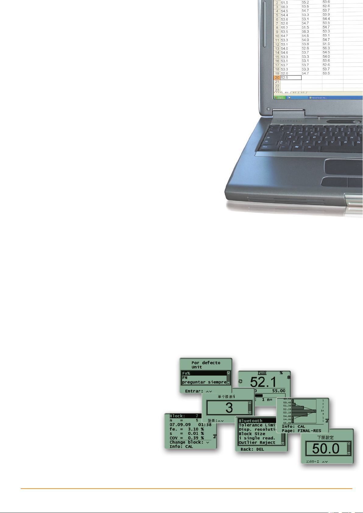
Simple and convenient evaluation of measurement
data through data transfer via Bluetooth® or cable
Data memory
Up to 20,000 readings and 100 applications for •
mea surement data and application-specific calibrations
Separation of the measurement data in up to 4,000 •
blocks
Date and time stamp for the blocks•
Evaluation
Statistical evaluation of measurement series with
•
mean value, standard deviation, max and min value,
range
Computation of the process capability indices c
•
and c
pk
Output of characteristic variance-analytical values•
Graphical measurement presentation as a histogram
•
with a Gaussian bell curve
Interfaces
USB port for data transfer to a PC or printer•
Optional Bluetooth•
®
module, interface for wireless
data transfer to a PC (up to 10 m)
Optional COM module, serial interface for data
•
transfer to a PC or printer (cable length up to 12 m)
Calibration
Only one calibration required for the entire rele-
•
vant measurement range from 0.1 to approx. 90 FN.
Adherence to the measurement accuracy specified
in standard AWS A4.2M
Calibration using calibration standards traceable
•
to TWI secondary standards or customer-specific
standards
Linking applications: Common normalization/
•
calibration of applications
p
Large, easy to read graphical display in several languages

6
FERITSCOPE® FMP30
Calibration and measurement method
Calibration / Standards
To obtain comparable measurement results, the instruments must be adjusted or calibrated using standards
that can be traced to internationally recognized
secondary standards. For this purpose, the IIW (Inter national Institute of Welding, UK) developed secondary standards that have been determined by the
TWI (The Welding Institute, UK) according to the
method described in DIN EN ISO 8249 and
AWS A4.2M.
Helmut Fischer offers certified calibration standard sets
that are traceable to the TWI secondary standards for
corrective and master calibrations. The standards of
the Fischer calibration standard sets list in addition to
the ferrite numbers FN also the % Fe values.
Influences including the shape of the part to be
measured (strong curvature, thickness of the ferritecontaining coating, etc.) can be taken into account
through corrective calibrations with customer-specific
calibration standards or through correction factors
(included). The normalization and corrective calibration are stored application-specific in the respective
application memory of the instrument.
Magnetic induction method
The FERITSCOPE FMP30 measures according to the
magnetic induction method. A magnetic field generated by a coil begins to interact with the magnetic
portions of the specimen. The changes in the magnetic
field induce a voltage proportional to the ferrite content
in a second coil. This voltage is then evaluated. All
magnetic portions in the otherwise non-magnetic structure are measured, i. e., in addition to delta ferrite and
other ferritic portions also strain-induced martensite,
for example.
A specific advantage of the magnetic induction meth-
od for measuring the ferrite content is that a sigma
phase, i. e., a Fe-Cr precipitation, which has formed
due to excess ferrite content and unfavorable cooling
conditions, for example, is recognized correctly as
a non-ferritic structural component. In comparison,
erroneous interpretation of ferrite content is likely in
a metallographic section where a sigma phase is not
easily distinguished from a ferritic structure.
Fischer calibration standard set with certificate
7
Ordering Information
Standard content of shipment Order no.
FERITSCOPE FMP30 instrument, wrist strap, case, battery set, short form operating
instructions printed, operator’s manual and USB driver on CD, interface cable FMP/PC
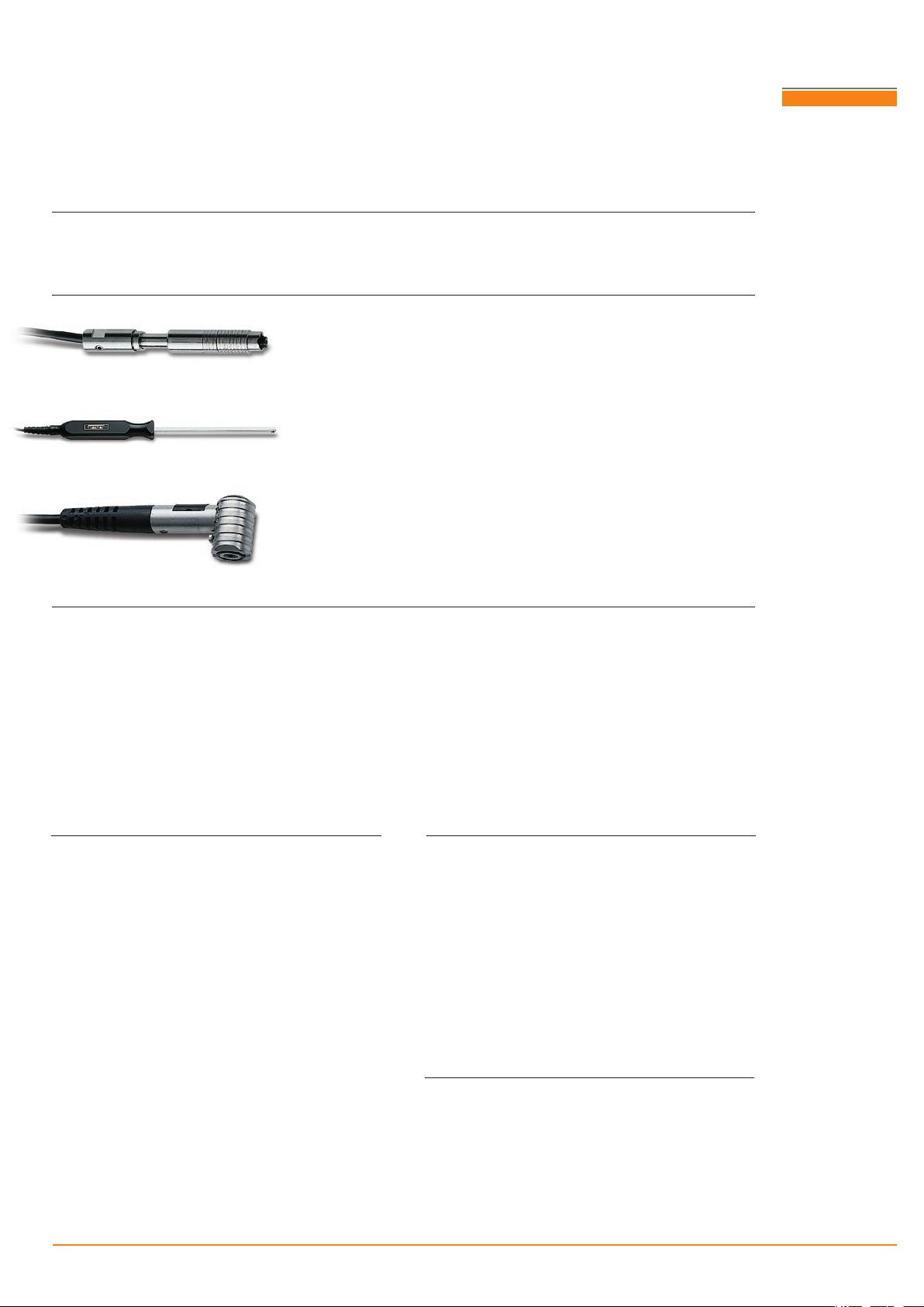
Probes with a measurement range 0.1 – 80 % Fe or 0.1 – 110 WRC-FN
FGAB1.3 -F e For measurements on flat and curved areas 604-264
FGA06H- Fe For measurements on flat and curved
surfaces. Very robust through a
particularly wear-resistant probe tip
FGABI1.3-150-Fe
FGABI1.3-260-Fe
Ideal for measurements in pipes,
bore holes or grooves
Insertion diameter > 9 mm
Shank length = 150 mm or 260 mm
FGABW1.3-Fe Angle probe for measurements on flat
specimens or in pipes, bore holes and gaps
Calibration standard sets
Corrective calibration standard set CAL-SS % Fe-WRC 0.3/10 includes standards about:
0.4, 2 and 9 FN (0.4, 2.5 and 10.5 % Fe)
Corrective calibration standard set CAL-SS % Fe-WRC 1.5/30 includes standards about:
2, 9 and 33 FN (2.5, 10.5 and 30 % Fe)
604-300
604-303
604-254
604 -341
604-337
602-279
602-239
Corrective calibration standard set CAL-SS % Fe-WRC 10/80 includes standards about:
9, 33 and 110 FN (10.5, 30 and 80 % Fe)
Calibration standard set CAL-SS % Fe-WRC 0.3/80 includes standards about:
0.5, 2, 13, 33 and 90 FN (0.5, 2.5, 14.5, 30 and 63 % Fe)
Optional accessories
Adapter E-probe/F-socket 604 -214
AC adapter FMP 30-40 604-290
Instrument upgrade
Bluetooth
®
Module FMP30/40, interface for the wireless data transfer from
the instrument to a PC (max. 10 m)
Rechargeable battery set FMP (NiMH) 604-295
COM Module FMP30/40, serial inter -
Battery charger AA/Mignon 604-335
Bluetooth
®
USB stick, for retrofitting
604 -4 81
face (RS232) for data transfer to a PC
or printer (max. cable length 12 m)
the PC with Bluetooth interface
USB printer cable DK-FMP 604 -145
Printer F6100 604-291
Software MP-Name, Software
602-966
Spare parts
for naming of applications
Wrist strap FMP 604-150
Software PC-DATEX, Software for
data transfer to Excel spreadsheets
Software PC-DATACC, Software for
data transfer to Access data bases
602-465
603- 028
Interface cable FMP/PC 604 -146
Battery set FMP (Alkaline) 604-296
Instrument case FMP 604 -148
602-277
602- 776
604-480
604-500
FERITSCOPE® is a registered trademark of Helmut Fischer GmbH Institut für Elektronik und Messtechnik, Sindelfingen/Germany.
Bluetooth® is a registered trademark of Bluetooth SIG, USA.

Fischer Worldwide
Helmut Fischer GmbH
Institut für Elektronik und Messtechnik
71069 Sindelfingen, Germany
Tel. +49 70 31 30 30
mail@helmut-fischer.de
Fischer Instrumentation (GB) Ltd
Lymington / Hampshire SO41 8JD, England
Tel. +44 15 90 68 41 00
mail@fischergb.co.uk
Fischer Technology, Inc.
Windsor, CT 06095, USA
Tel. +1 860 683 07 81
info@fischer-technology.com
Helmut Fischer AG
CH-6331 Hünenberg, Switzerland
Tel. +41 41 785 08 00
switzerland@helmutfischer.com
Fischer Instrumentation Electronique
78180 Montigny le Bretonneux, France
Tel. +33 1 30 58 00 58
france@helmutfischer.com
Helmut Fischer S.R.L.
Tecnica di Misura, 20128 Milano, Italy
Tel. +39 0 22 55 26 26
italy@helmutfischer.com
Fischer Instruments, S.A.
08018 Barcelona, Spain
Tel. +34 9 33 09 79 16
spain@helmutfischer.com
Helmut Fischer Meettechniek B.V.
5627 GB Eindhoven, The Netherlands
Tel. +31 40 248 22 55
netherlands@helmutfischer.com
Fischer Instruments K.K.
Saitama-ken 340-0012, Japan
Tel. +81 4 89 29 34 55
japan@helmutfischer.com
Fischer Instrumentation (Far East) Ltd
Kwai Chung, N.T., Hong Kong
Tel. +852 24 20 11 00
hongkong@helmutfischer.com
Fischer Instrumentation (S) Pte Ltd
Singapore 658065, Singapore
Tel. +65 62 76 67 76
singapore@helmutfischer.com
Nantong Fischer Instrumentation Ltd
Shanghai 200333, P. R. China
Tel. +86 21 32 51 31 31
china@helmutfischer.com
Fischer Measurement Technologies (India) Pvt. Ltd
Pune 411036, India
Tel. + 91 20 26 82 20 65
india@helmutfischer.com
www.helmut-fischer.com
05-09
902-039 01/11
Coating Thickness Material TestingMicrohardnessMaterial Analysis
 Loading...