

fischertechnik ROBO TX Instruction Manual
2
ROBO TX CO n T R O l l e R
Mode d'emploi du ROBO TX Controller
Avec des informations utiles en matière d'installation, de commande et de
recherche de la cause de perturbations.
F
Page 36 – 51
Instruction Manual for the ROBO TX Controller
Includes instructions for installation, operation and troubleshooting.
Page 20 – 35
Gebruiksaanwijzing voor de ROBO TX Controller
Onder andere met instructies voor de installatie, bediening en opsporing van storingen.
NL
Pagina 52– 67
Manual de instrucciones para el ROBO TX Controller
Entre otras con indicaciones para la instalación, manejo y búsqueda de anomalías.
E
Página 68 – 83
Instruções de operação para o ROBO TX Controller
Entre outros com avisos para a instalação, comando e busca de falhas.
P
Página 84 – 99
Manuale di istruzioni del ROBO TX Controller
Contiene anche indicazioni sull'installazione, l'impiego e la ricerca guasti.
I
Pag. 100 – 115
Инструкция по эксплуатации ROBO TX Controller
В том числе с рекомендациями по монтажу, управлению и поиску неисправностей.
RU
Страница 116 – 131
ROBO TX Controller 控制器的操作说明书:
此外还有关于安装、操作和故障查找的说明.
CN
第 132 – 147 页
Bedienungsanleitung für den ROBO TX Controller
Unter anderem mit Hinweisen zur Installation, Bedienung und Störungssuche.
Seite 4 – 19
D
ROBO TX CO n T R O l l e R
D
3
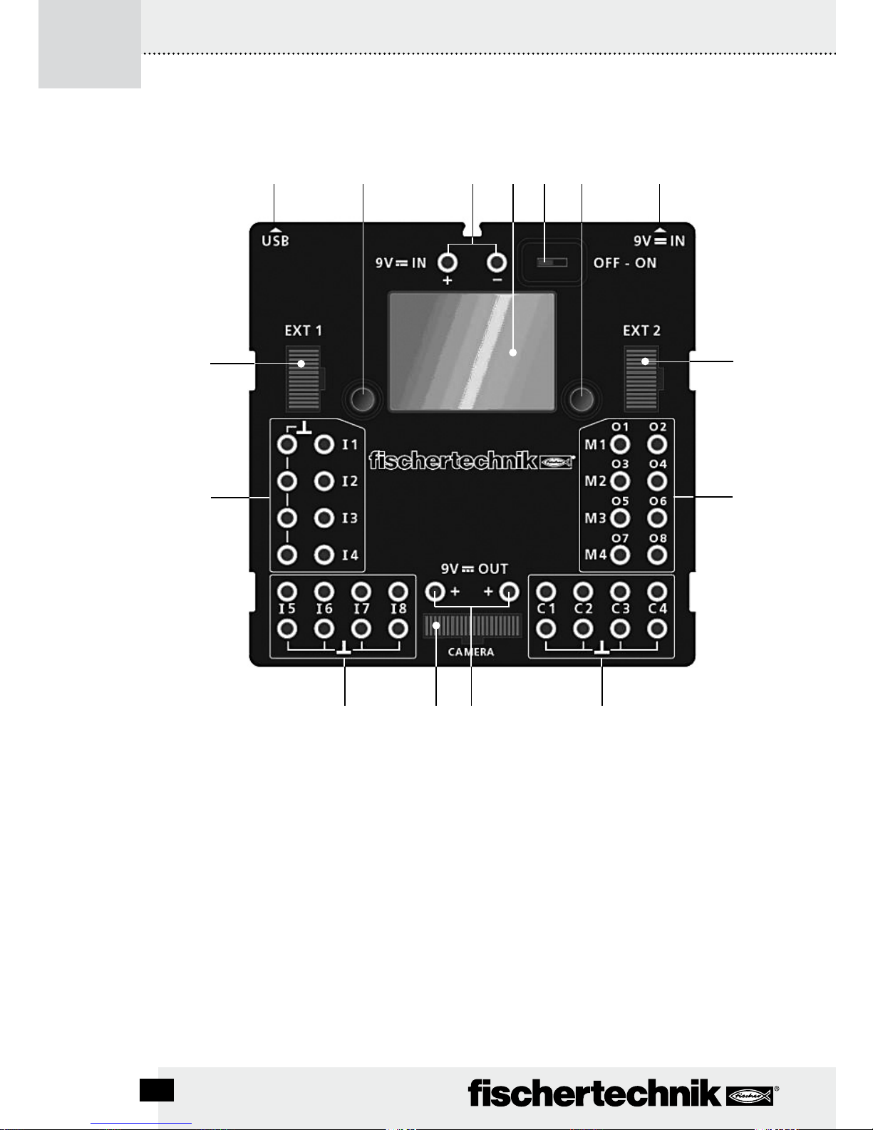
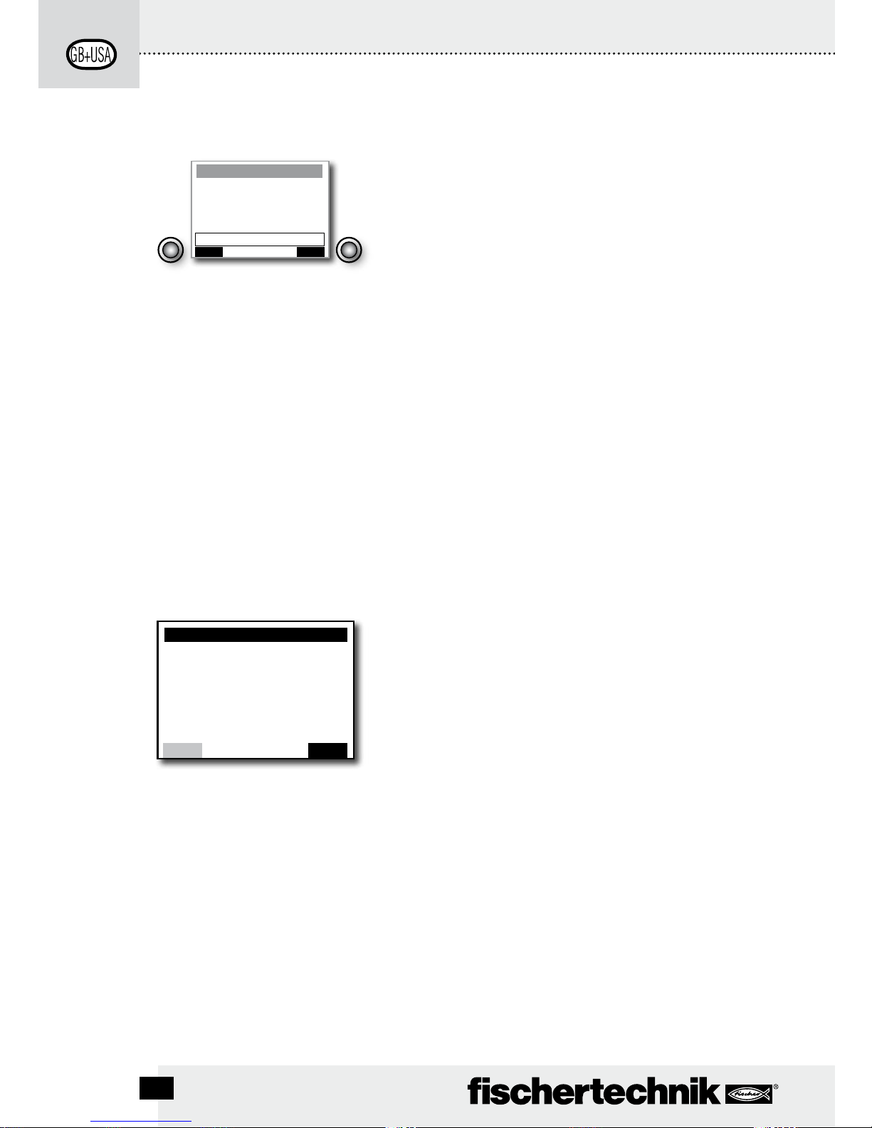
Beschreibung zur Abbildung siehe Seite 4.
Description for figure see page 20.
La description des points de la figure vous est donnée à la page 36.
Voor beschrijving bij de afbeelding zie pagina 52.
Véase descripción de la ilustración en página 68.
Descrição para a ilustração, ver a página 84.
Per la descrizione della figura, vedi pagina 100.
Описание к рисунку см. на стр. 116.
对插图的说明请参阅第 132 页。
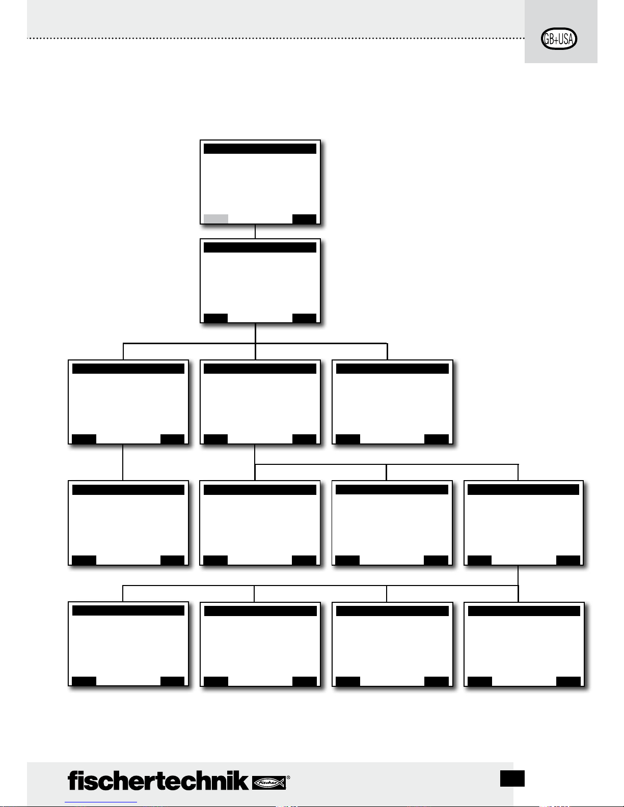
1 2 3
54 76
8
9
10111213
13
14
ROBO TX CO n T R O l l e R Be d i e n u n g s a n l e i T u n g
D
4
Beschreibung zur Abbildung auf Seite 3:
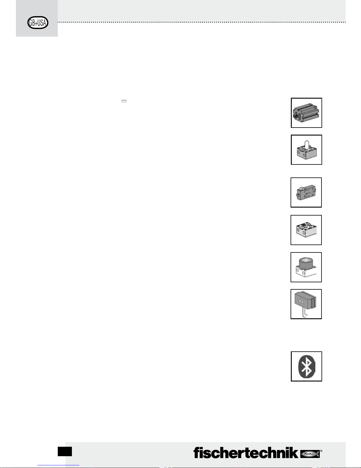
USB Anschluss1.
Auswahltaste links2.
9 V3. IN, Anschluss Accu Pack
Display4.
Ein-/Ausschalter5.
Auswahltaste rechts6.
9 V7. IN, DC-Buchse für Netzgerät (+ = innen)
INHALT
ROBO TX Controller ....................................................................................................S.5
Bestimmungsgemäße Verwendung ......................................................................S.5
Sicherheitshinweise..................................................................................................S.5
Das kann an den ROBO TX Controller angeschlossen werden .........................S.6
Wozu sind die Buchsen, Stecker, Taster und Schalter? .....................................S.7
Software installieren .................................................................................................S.8
Einstellen (Menü) .......................................................................................................S.9
Menü-Übersicht .....................................................................................................S.9
Menü im Detail ....................................................................................................S.10
Einschalten ................................................................................................................S.14
Programm auswählen und starten ........................................................................S.14
Ausschalten ...............................................................................................................S.14
Erweiterungen...........................................................................................................S.14
Bluetooth Verbindungen .........................................................................................S.15
Störungen ...................................................................................................................S.17
Technische Daten .....................................................................................................S.18
Richtig entsorgen .....................................................................................................S.19
Gewährleistung ........................................................................................................S.19
Haftung .......................................................................................................................S.19
EXT 2, Anschluss für Erweiterungen8.
Ausgänge M1–M4, bzw. O1–O89.
10. Schnelle Zähleingänge C1–C4
11. 9 V OUT, Spannungsausgang
12. Kamera Anschluss
13. Universal Eingänge I1–I8
14. EXT 1, Anschluss für Erweiterungen

D
5
ROBO TX CO n T R O l l e R Be d i e n u n g s a n l e i T u n g
ROBO TX Controller
Hightech pur steckt in dem kompakten Gehäuse des ROBO TX Controllers. Auf diese Steuerung
lassen sich Programme laden, die dann Motoren, Lampen und sogar ganze fischertechnik Roboter steuern – und das ist noch nicht alles:
Ein USB-Anschluss und die integrierte Bluetooth-Funkschnittstelle ermöglichen eine beque-•
me und schnelle Verständigung zwischen Computer und dem fischertechnik Modell.
Der große RAM-Speicher und der zusätzliche Flash-Speicher des ROBO TX Controllers spei-•
chern zahlreiche Programme gleichzeitig.
Mit dem Controller können alle Modelle der COMPUTING-Reihe gesteuert werden.•
Darüber hinaus kann der Controller auch mit anderen Bluetooth-fähigen Geräten oder mit •
maximal acht weiteren ROBO TX Controllern kommunizieren.
Durch die fischertechnik Nuten an fünf Seiten und die kompakten Maße lässt sich der ROBO •
TX Controller platzsparend in die fischertechnik Anlagen und Modelle einbauen.
Bestimmungsgemäße Verwendung
Der Controller darf ausschließlich zum Betreiben und zur Steuerung von fischertechnik Modellen
eingesetzt werden.
Sicherheitshinweise
Ladegerät regelmäßig auf Schäden prüfen.•
Bei einem Schaden darf das Ladegerät bis zur vollständigen Reparatur nicht mehr verwendet •
werden.
Drähte nicht in Steckdose einführen!•
Nichtaufladbare Batterien dürfen nicht aufgeladen werden!•
Aufladbare Batterien vor dem Laden aus dem Batteriefach entnehmen!•
Aufladbare Batterien nur unter Aufsicht Erwachsener laden!•
Batterien mit der richtigen Polarität einlegen!•
Anschlussklemmen dürfen nicht kurzgeschlossen werden!•
Der ROBO TX Controller darf nur mit fischertechnik Stromversorgung wie z. B. Accu Pack •
35537 betrieben werden!
Beim Anschluss des Accu Packs an den Controller folgendes beachten: •
Pluspol des „9 V
IN“-Anschlusses mit dem Pluspol (+) des Accu Packs verbinden!
Minuspol des „9 V
IN“-Anschlusses mit dem Minuspol (–) des Accu Packs verbinden!
Betriebstemperatur maximal 40°C!•

ROBO TX CO n T R O l l e R Be d i e n u n g s a n l e i T u n g
D
6
Das kann an den ROBO TX Controller angeschlossen
werden
Folgende Geräte können angeschlossen bzw. angesteuert werden. Darüber
hinaus kann der Controller um zusätzliche Geräte erweitert werden:
Aktoren (mit 9 V
, 250 mA)
Elektromotoren
Glühlampen
Summer
Elektromagneten
Magnetventile (aus den Pneumatik-Baukästen)
Sensoren (Digital 5 kΩ, Digital 10 V ; Analog 0 –5 kΩ, Analog 0 –10 V)
Taster
Magnet-Sensoren (Reedkontakte)
Licht-Sensoren (Fototransistoren, Fotowiderstände)
Wärme-Sensoren (NTC-Widerstände)
Ultraschall-Sensoren (nur die Version TX Art. Nr. 133009 mit dreiadrigem
Anschluss)
Farbsensoren
Infrarot-Sensoren (Spursensoren)
Potentiometer
Magnet-Encoder
ROBO TX Controller
Bis zu 8 zusätzliche Controller können über Erweiterungsstecker angekoppelt
werden.
Kamerasensor
Sobald verfügbar
Funkübertragung
Per Bluetooth kann eine Verbindung zu anderen Bluetooth-Geräten aufgenommen
werden, wie z. B. PC, andere ROBO TX Controller, Handy.

D
7
ROBO TX CO n T R O l l e R Be d i e n u n g s a n l e i T u n g
Wozu sind die Buchsen, Stecker, Taster und Schalter?
Abbildung siehe Seite 3
1 USB 2.0 Anschluss (1.1 kompatibel):
Stellt die Verbindung zum PC her. Das passende USB Kabel liegt bei.
2 Auswahltaste links
Damit wird das Display-Menü gesteuert. Mehr dazu im Kapitel Menü.
3 9 V
IN, Anschluss Accu Pack
Dieser Anschluss ermöglicht eine mobile Stromversorgung über den fischertechnik Accu
Pack (nicht im Lieferumfang), als Alternative zum Netzgerät.
4 Display
Das Display zeigt den Status des Controllers, welche Programme geladen sind und wo man
sich im Menü befindet. Es lassen sich Funktionen und Programme auswählen, aktivieren
oder deaktivieren. Während ein Programm läuft kann man sich Werte von Variablen
(Variablenwerte) oder Werte von analogen Sensoren anzeigen lassen. Eine hilfreiche
Menü-Übersicht ist im Kapitel „Einstellen (Menü)“ abgebildet.
5 Ein-/Ausschalter
Schaltet die Stromzuführung zum Controller ein oder aus.
6 Auswahltaste rechts
Damit wird das Display-Menü gesteuert. Mehr dazu im Kapitel Menü.
7 9 V
IN, DC-Buchse
Hier wird das Netzgerät vom Power Set/Energy Set angeschlossen (nicht im Lieferumfang).
Ein passender Adapter liegt dem Controller bei.
8 EXT 2, Anschluss für Erweiterungen
Über diesen Anschluss können weitere ROBO TX Controller angekoppelt und so die Anzahl
der Ein- und Ausgänge erweitert werden. Außerdem enthält er eine I
2
C-Schnittstelle für
zukünftige Erweiterungen.
9 Ausgänge M1– M4 bzw. O1– O8
An die Ausgänge können 4 Motoren angeschlossen werden. Alternativ 8 Lampen oder
Elektromagnete, deren zweiter Pol mit einem Masseanschluss (
) verbunden wird.
10 Eingänge C1– C4
Schnelle Zähleingänge, erfassen Zählimpulse bis 1 kHz (1000 Impulse/sec.) z. B. vom
Encodermotor des ROBO TX Training Lab Baukastens. Auch als digitale Eingänge, z. B. für
Taster nutzbar.
11 9 V Out
Versorgt Sensoren mit der nötigen Betriebsspannung 9 V
, wie z. B. Farbsensor, Spursen-
sor, Ultraschallsensor, Magnet-Encoder.
12 CAMERA-Anschluss
Anschlussmöglichkeit für ein Kameramodul (z. Zt. der Drucklegung in Vorbereitung).
ROBO TX CO n T R O l l e R Be d i e n u n g s a n l e i T u n g
D
8
13 Universal-Eingänge I1– I8
Das sind die Alleskönner unter den Signaleingängen. Sie sind über die Software ROBO Pro
einstellbar für:
•DigitaleSensoren(Taster,Reed-Kontakte,Fototransistoren)–Digital5kΩ
•Infrarot-Spursensoren–Digital10V
•AnalogeSensoren0–5 kΩ (NTC-Widerstände, Fotowiderstände, Potentiometer)
•AnalogeSensoren0–10 V(Farbsensoren)AnzeigedesWertesinmV(Millivolt)
•Ultraschall-Abstandssensoren(nurdieVersionTXmitdreiadrigemAnschluss)
14 EXT 1, Anschluss für Erweiterungen
Über diesen Anschluss können wie auch an EXT 2 weitere ROBO TX Controller angekoppelt
und so die Anzahl der Ein- und Ausgänge erweitert werden.
Software installieren
Softwarevorraussetzung für den ROBO TX Controller:
ROBO Pro Version 2.0 oder höher.
Im Handbuch der ROBO Pro Software wird unter Anderem detailliert beschrieben:
•DieInstallationderSoftwareROBOProaufdemPC
Die Installation des USB-Treibers für den ROBO TX Controller für Windows Betriebssysteme•
D
9
ROBO TX CO n T R O l l e R Be d i e n u n g s a n l e i T u n g
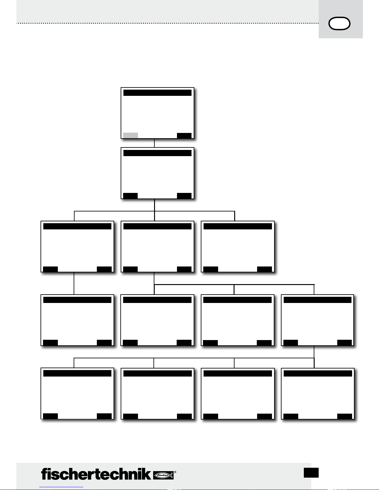
Einstellen (Menü)
Menü-Übersicht
Menü
Datei
Einstellungen
Info
Zurück
È
OK
<– Doppelklick für
Richtungs Wechsel
Info
Firmware: V x.x.x
Name: ROBO TX
Bluetooth: xx:xx:xx:xx:xx:xx
Zurück
È
OK
<– Doppelklick für
Richtungs Wechsel
Einstellungen
Eigenschaft: Master
Sprache: Deutsch
Bluetooth: Ein
Auf Standard zurücksetzen:
Zurück
È
OK
<– Doppelklick für
Richtungs Wechsel
Bluetooth
Ein
Aus
Zurück
È
OK
<– Doppelklick für
Richtungs Wechsel
Gerät sichtbar
Ja
Nein
Zurück
È
OK
<– Doppelklick für
Richtungs Wechsel
Verbindung erlaubt
Ja
Nein
Zurück
È
OK
<– Doppelklick für
Richtungs Wechsel
Gekoppelte Geräte
Alle löschen
Zurück
È
OK
<– Doppelklick für
Richtungs Wechsel
Sprache
English
Deutsch
Français
Nederlands
...
È
OK
<– Doppelklick für
Richtungs Wechsel
Bluetooth
Bluetooth: Ein
Gerät sichtbar: Ja
Verbindung erlaubt: Ja
Gekoppelte Geräte: 0
Auf Standard zurücksetzen:
Zurück
È
OK
<– Doppelklick für
Richtungs Wechsel
Eigenschaft
Master
Extension 1
...
...
Extension 8
Zurück
È
OK
<– Doppelklick für
Richtungs Wechsel
X/Programmname
Start
Laden
Auto Start
Auto Load
Löschen
Zurück
È
OK
<– Doppelklick für
Richtungs Wechsel
Datei
R/Programmname 1
F/Programmname 2
Programmspeicher leeren
Zurück
È
OK
<– Doppelklick für
Richtungs Wechsel
<– Doppelklick für
Richtungs Wechsel
ROBO TX
-> Lokal
-> Kein Programm geladen
-> Master
-> Ext.
Menü
Start
ROBO TX CO n T R O l l e R Be d i e n u n g s a n l e i T u n g
D
10
* Master: Der Controller, der als Master eingestellt ist erhält Steuerbefehle direkt vom PC und gibt sie an die Extensions
weiter. Extension: Der Controller, der als Extension eingestellt ist erhält Steuerbefehle nur über den Master.
Menü im Detail
Navigation über Auswahltasten:
Tippt man den • linken Auswahltaster wechselt ein
Auswahlrahmen von einer Zeile zur nächsten. Durch einen
Doppelklick wechselt der Auswahlrahmen die Laufrichtung. Im Statusfenster hat der linke Auswahltaster eine
Start/Stopp-Funktion.
Tippt man den • rechten Auswahltaster wird die vorher
getroffene Auswahl bestätigt. Dadurch gelangt man in
ein nächstes Menü oder aktiviert/deaktiviert bestimmte
Funktionen. Im Statusfenster gelangt man mit dem rechten
Auswahltaster immer ins Hauptmenü.
Wählt man • „Zurück“ aus, gelangt man immer wieder in
das vorherige Menü zurück.
Zuerst muss einmal die gewünschte Landessprache
eingestellt werden. Im Auslieferungszustand ist Englisch
eingestellt.
Menu | Settings | Language | gewünschte Sprache auswählen und mit OK übernehmen.
Hinweis: Mit „/“ getrennt sind Texte, die alternativ in der
gleichen Zeile erscheinen können.
Das Statusfenster
Zeile 1: Lokal / Online
Lokal: kein Datenaustausch mit dem PC (als Master*) oder
keine Verbindung zum Master (als Extension*).
Online: Master* tauscht Daten mit dem PC aus oder Extension* ist mit Master* verbunden.
Zeile 2: Kein Programm geladen / geladen: Programm-
name / gestartet: Programmname
Zeigt an, ob ein Programm geladen ist und wenn ja, in welchem Zustand es sich befindet.
Zeile 3: Master* / Extension* 1–8
Zeigt an für welche Funktion der Controller eingestellt
wurde, Master* oder Extension*. Änderungen sind im Menü
Eigenschaft möglich.
ROBO TX
-> Lokal
-> Kein Programm geladen
-> Master
-> Ext.
Menü
Start
Zurück
È
OK
D
11
ROBO TX CO n T R O l l e R Be d i e n u n g s a n l e i T u n g
Zeile 4: Ext.
Es wird angezeigt welche Extensions angeschlossen sind,
z. B. 1, 2, ... 8 (wird nur angezeigt, wenn Extensions angeschlossen sind).
Fußzeile: Start / Stop
Startet oder stoppt ein Programm. Das Start/Stop-Feld wird
nur angezeigt, wenn eine Programmdatei per Download vom
PC auf den Controller übertragen wurde, oder vom Flashspeicher in den Programmspeicher geladen wurde.
Das Hauptmenü
Zeile 1: Datei
Führt zum Menü Dateiauswahl.
Zeile 2: Einstellungen
Führt zum Menü Einstellungen.
Zeile 3: Info
Führt zur Anzeige Info.
Die Dateiauswahl
Sind Programmdateien per Download vom PC auf den
Controller übertragen worden, so sind sie hier aufgelistet.
Sie können dann ausgewählt, mit Startfunktionen belegt oder
gelöscht werden (siehe Menü X/Programmname).
R/ bedeutet: Datei liegt im RAM.
F/ bedeutet: Datei liegt im Flashspeicher.
Steht vor der Datei (AL) oder (AS) ist für diese Datei AutoLoad oder Auto-Start aktiviert, z. B. (AS)F/ROB3.
Programmspeicher leeren
Auswahl „Programmspeicher leeren“ | bestätigen mit OK.
Die in den Programmspeicher geladene Datei wird dort entfernt. Programmdateien im Flashspeicher bleiben erhalten.
Menü
Datei
Einstellungen
Info
Zurück
È
OK
<– Doppelklick für
Richtungs Wechsel
Datei
R/Programmname 1
(AS)F/Programmname 2
Auto-Load/Auto-Start ausschalten
Programmspeicher leeren
Zurück
È
OK
<– Doppelklick für
Richtungs Wechsel
ROBO TX CO n T R O l l e R Be d i e n u n g s a n l e i T u n g
D
12
* Master: Der Controller, der als Master eingestellt ist erhält Steuerbefehle direkt vom PC und gibt sie an die Extensions
weiter. Extension: Der Controller, der als Extension eingestellt ist erhält Steuerbefehle nur über den Master.
** Die Firmware ist die Betriebssoftware des Controllers.
Die Einstellungen
Zeile 1: Eigenschaft: Master / Extension
Führt zum Menü Eigenschaft. Dort wird zugewiesen ob der
Controller als Master* oder Extension* funktionieren soll.
Zeile 2: Sprache: Deutsch / English / ...
Führt zum Menü Sprachen.
Zeile 3: Bluetooth:
Führt zum Menü Bluetooth.
Zeile 4: Auf Standard zurücksetzen:
Stellt die ursprünglichen Werkseinstellungen wieder her.
Das Infofenster
Zeile 1: Firmware:
Zeigt die Versionsnummer der Firmware** an.
Zeile 2: Name:
Der Name des Geräts wird angezeigt (z. B. ROBO TX 622).
Zeile 3: Bluetooth:
Eindeutiger Bluetooth Identifikationscode des Geräts
(Bluetooth-Standard).
X/Programmname
Zeile 1: Start
Das ausgewählte Programm wird gestartet.
Zeile 2: Laden
Das ausgewählte Programm wird in den Programmspeicher
geladen, und kann auf Knopfdruck gestartet werden.
Zeile 3: Auto Start
Sobald die Stromversorgung am Controller eingeschaltet
wird, startet das ausgewählte Programm automatisch.
Zeile 4: Auto Load
Sobald die Stromversorgung eingeschaltet wird, lädt sich das
ausgewählte Programm automatisch in den Programmspeicher und kann auf Knopfdruck gestartet werden.
Zeile 5: Löschen
Ausgewähltes Programm wird gelöscht (zuvor erscheint noch
eine Sicherheitsabfrage).
Einstellungen
Eigenschaft: Master
Sprache: Deutsch
Bluetooth: Ein
Auf Standard zurücksetzen:
Zurück
È
OK
<– Doppelklick für
Richtungs Wechsel
Info
Firmware: V x.x.x
Name: ROBO TX
Bluetooth: xx:xx:xx:xx:xx:xx
Zurück
È
OK
<– Doppelklick für
Richtungs Wechsel
X/Programmname
Start
Laden
Auto Start
Auto Load
Löschen
Zurück
È
OK
<– Doppelklick für
Richtungs Wechsel

D
13
ROBO TX CO n T R O l l e R Be d i e n u n g s a n l e i T u n g
Die Eigenschaft
Hier wird dem Controller die Eigenschaft als Master oder als
Extension 1 ... 8 zugewiesen. Einfach auswählen und mit OK
bestätigen. Mehr zum Thema im Kapitel „Erweiterungen“.
Die Sprachen
Hier kann die im Display verwendete Sprache geändert
werden. Einfach auswählen und mit OK bestätigen.
Bluetooth
Wird eine der Zeilen 1–5 ausgewählt, öffnet sich ein Menü,
in dem die jeweiligen Funktionen ein-/ausgeschaltet oder
umgestellt werden können.
Zeile 1: Bluetooth:
Die Bluetooth Funktion wird hier ein- oder ausgeschaltet.
Zeile 2: Gerät sichtbar:
Ist die Funktion eingeschaltet, können andere BlutoothGeräte den ROBO TX Controller erkennen.
Zeile 3: Verbindung erlaubt
Ist die Funktion eingeschaltet, erlaubt der ROBO TX Controller
anderen Geräten eine Bluetooth-Verbindung mit ihm aufzunehmen.
Zeile 4: Gekoppelte Geräte:
Zeigt an, wie viele Geräte mit dem Controller über Bluetooth
verbunden sind.
Zeile 5: Auf Standard zurücksetzen:
Stellt die ursprünglichen Werkseinstellungen wieder her.
Eigenschaft
Master
Extension1
...
...
...
Extension 8
Zurück
È
OK
<– Doppelklick für
Richtungs Wechsel
Sprache
English
Deutsch
Français
Nederlands
Español
...
È
OK
<– Doppelklick für
Richtungs Wechsel
Bluetooth
Bluetooth: Ein
Gerät sichtbar: Ja
Verbindung erlaubt: Ja
Gekoppelte Geräte: 0
Auf Standard zurücksetzen:
Zurück
È
OK
<– Doppelklick für
Richtungs Wechsel

ROBO TX CO n T R O l l e R Be d i e n u n g s a n l e i T u n g
D
14
Einschalten
Beim erstmaligen Anschluss des Controllers an den PC muss der Treiber für die USB-Schnittstelle auf dem PC installiert werden. Die Einzelheiten sind im Handbuch „ROBO Pro Software“
beschrieben.
USB-Kabel mit PC verbinden.1.
Netzgerät in die Steckdose stecken (oder Accu Pack anschließen).2.
Den kleinen Stecker des Netzgerätes in die 9 V3.
IN Eingangsbuchse (7) des Controllers
stecken (falls nötig liegt dem Controller ein Adapter bei).
Controller am Ein-/Ausschalter (5) einschalten.4.
Es erscheint kurz ein Begrüßungstext mit der Firmware-Versionsnummer. Danach wird das 5.
Statusfenster angezeigt. Das ist der Ausgangspunkt für die Navigation im Controller-Menü
(siehe Kapitel „Menü im Detail“).
Programm auswählen und starten
Zuerst muss ein Programm per Download vom PC auf den ROBO TX Controller übertragen 1.
werden. Ein Test der Verbindung und die genaue Vorgehensweise für den Programmdownload ist im Handbuch „ROBO Pro Software“ beschrieben.
Nach dem Download:
In der Grundeinstellung startet das Programm automatisch. 2.
Gestoppt wird der Ablauf durch Drücken der linken Auswahltaste (2).3.
Veränderungen im Startverhalten können jeder Programmdatei einzeln zugewiesen werden, wie
z. B. Auto-Start oder Auto-Load. Möglich ist das im Menü X/Programmname:
Menü | Einstellungen | Datei | R/Programmname oder F/Programmname | ...
Einzelheiten zu den jeweiligen Funktionen sind im Kapitel „Menü im Detail“ beschrieben.
Ausschalten
Den Ein-/Ausschalter (5) in Stellung OFF schieben (und das Netzteil aus der Steckdose ziehen).
Erweiterungen
Über spezielle Anschlüsse können weitere ROBO TX Controller oder eine Kamera angeschlossen werden.
Weitere ROBO TX Controller
Mit weiteren Controllern wird die Anzahl der Ein- und Ausgänge erweitert. Über die speziellen
Anschlüsse EXT 1 und EXT 2 werden sie angekoppelt.
Stromversorgung über Netzgerät oder Accu Pack herstellen.1.
Dem neuen Controller die Funktion als Extension 1, 2, ... oder 8 zuweisen: 2.
Menü | Einstellungen | Eigenschaft | Extension 1, 2, ... oder 8 | OK

D
15
ROBO TX CO n T R O l l e R Be d i e n u n g s a n l e i T u n g
Die Controller mit dem beiliegenden Flachbandkabel untereinander verbinden. Welcher 3.
Anschluss dabei verwendet wird (EXT 1 oder EXT 2), ist egal.
Im Statusfenster des Controllers wird die neue Extension in der letzten Zeile aufgeführt.4.
Kamerasensor
Ist zum Zeitpunkt der Drucklegung in Vorbereitung.
I
2
C-Schnittstelle
Diese Standardschnittstelle ist für zukünftige Erweiterungen vorgesehe, z. B. für spezielle
Sensoren.
Bluetooth Verbindungen
Bluetooth Verbindung zwischen ROBO TX Controller PC
Diese Bluetooth-Verbindung ersetzt das USB-Verbindungskabel durch eine drahtlose Funkverbindung. Der ROBO TX Controller kann damit im Onlinemodus angesprochen werden, d.h. das
Programm läuft auf dem PC und es findet ein andauernder Datenaustausch zwischen PC und
ROBO TX Controller statt. Es können über diese Bluetooth-Verbindung auch Programme auf den
Controller geladen werden, die dann dort unabhängig vom PC abgearbeitet werden.
Voraussetzungen:
Bluetoothfähiger PC oder handelsüblicher USB-Bluetooth Stick mit Windows-kompatiblem
Bluetooth Funk-Chip. Windows XP mit Service Pack 2 oder Windows Vista.
fischertechnik veröffentlicht eine Liste mit erfolgreich getesteten USB-Bluetooth-Sticks, die
problemlos mit dem ROBO TX Controller zusammen funktionieren. Es kommen ständig neue
Sticks auf den Markt, andere sind dafür nicht mehr erhältlich. Um stets aktuelle Informationen
bieten zu können ist dieser Service auf unserer Website unter
www.fischertechnik.de – Computing – Downloads – ROBO TX Controller
abrufbar. Dort befindet sich auch eine detaillierte Beschreibung wie unter Windows die
Bluetooth-Verbindung zwischen PC und ROBO TX Controller installiert wird.
Für Bluetooth Profis, die keine weitere Anleitung benötigen:
Der ROBO TX Controller verwendet als Hauptschlüssel die Ziffernfolge 1234.
Hinweis zur Reichweite:
Die Reichweite beträgt ca. 10 m und ist abhängig von der Qualität des USB-Bluetooth-Sticks
sowie von Umgebungsbedingungen (Störungen durch andere Geräte, Hindernisse im Raum).
ROBO TX CO n T R O l l e R Be d i e n u n g s a n l e i T u n g
D
16
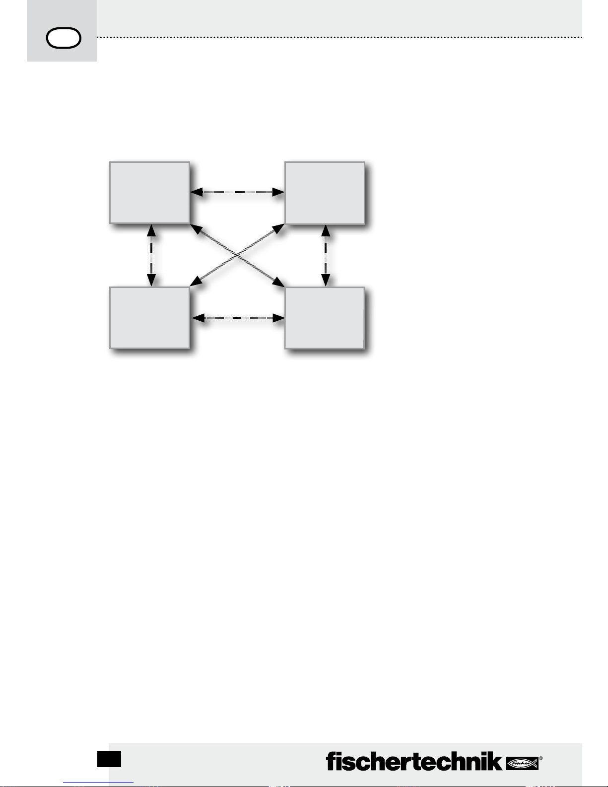
Bluetooth-Verbindung zwischen verschiedenen ROBO TX Controllern
Im Downloadbetrieb kann ein ROBO TX Controller mit bis zu 7 anderen ROBO TX Controllern
Daten austauschen. Dabei kann jedes Gerät zu jedem anderen Teilnehmer eine BluetoothVerbindung aufbauen und darüber Daten senden und empfangen.
In ROBO Pro sind spezielle Programmelemente zum Auf- und Abbau von Verbindungen sowie
zum Senden und Empfangen von Nachrichten enthalten.
Weitere Informationen zu dieser Betriebsart befinden sich in der Onlinehilfe zur Software ROBO
Pro (Version 2.0 oder höher).
Bluetooth Verbindung zwischen ROBO TX Controller und anderen Geräten (z. B.
Mobiltelefon)
Grundsätzlich kann der ROBO TX Controller auch mit anderen Bluetooth-Geräten wie z. B.
geeigneten Mobiltelefonen kommunizieren. Dazu muss auf dem jeweiligen Gerät eine spezielle,
auf den ROBO TX Controller abgestimmte Kommunikationssoftware vorhanden sein. Da auch
in diesem Bereich ständig Veränderungen zu erwarten sind, können aktuelle Informationen und
Links ebenfalls abgerufen werden unter:
www.fischertechnik.de – Computing – Downloads – ROBO TX Controller
ROBO TX
Controller
ROBO TX
Controller
ROBO TX
Controller
ROBO TX
Controller
D
17
ROBO TX CO n T R O l l e R Be d i e n u n g s a n l e i T u n g
Störungen
Elektromagnetische Störungen
Sollte der Controller durch externe elektromagnetische Einflüsse gestört werden, kann er nach
Ende der Störung bestimmungsgemäß weiter benutzt werden. Eventuell muss die Stromversorgung kurz unterbrochen und der Controller neu gestartet werden.
Fehlermeldungen (vom Controller oder der ROBO Pro Software)
Störung Ursache Beseitigung
Programm Versionsfehler Es wurde versucht ein ROBO
Pro Programm zu laden oder
zu starten, das zu einer älteren
Firmwareversion gehört und
daher nicht mehr kompatibel ist.
Programm mit neuester ROBO
Pro Version erneut auf ROBO TX
Controller laden.
Programmfehler 1 ROBO Pro Fehlermeldung:
Die Anzahl der Prozesse
im ROBO Pro Programm ist
größer als die maximal mögliche
Anzahl.
Im Reiter „Eigenschaften“ des
ROBO Pro Programms die „Mindestzahl Prozesse“ vergrößern.
Programmfehler 2 ROBO Pro Fehlermeldung:
Der Mindestspeicher pro Prozess
ist zu klein.
a) Im Reiter „Eigenschaften“ des
ROBO PRO Programms den
„Mindestspeicher pro Prozess
(download)“ vergrößern.
b) Eine Variable oder ein
Unterprogramm ruft sich
endlos selbst auf (Rekursion)
und bringt den Speicher zum
Überlaufen. Programm so
ändern, dass Rekursion nicht
mehr auftritt.
Programmdatei kann nicht
geöffnet werden
Programmdatei konnte nicht
geöffnet werden, weil sie im
Flashspeicher gelöscht wurde.
Programmdatei erneut auf den
ROBO TX Controller laden.
Lesefehler Programmdatei Programmdatei konnte nicht
gelesen werden, weil sie zu groß
ist und nicht in den Programmspeicher passt.
Programmdatei muss so umprogrammiert werden, dass sie
weniger Speicherplatz benötigt.
ROBO TX CO n T R O l l e R Be d i e n u n g s a n l e i T u n g
D
18
Technische Daten
Maße und Gewicht
90 x 90 x15 mm (L x B x H)
90 g
Speicher und Prozessor
8 MB RAM, 2 MB Flash
32-bit ARM 9 Prozessor (200 MHz); programmierbar mit ROBO Pro Software oder C-Compiler
(nicht enthalten)
Stromversorgung (nicht enthalten)
Über Accu Set (8,4 V 1500 mAh) oder
Power Set (9 V / 1000 mA)
Schnittstellen
USB 2.0 (1.1 kompatibel), max. 12 Mbit, Mini USB-Buchse
Bluetooth Funkschnittstelle (2,4 GHz/Reichweite ca. 10 m)
2 x Erweiterungsanschlüsse: RS 485; I
2
C (nur EXT 2)
PIN-Belegung EXT 1:
6 5
6: nicht angeschlossen 5: nicht angeschlossen
4 3
4: RS485-B 3: RS485-A
2 1
2: nicht angeschlossen 1: GND
PIN-Belegung EXT 2:
6 5
6: I2C Clock 5: I2C Data
4 3
4: RS485-B 3: RS485-A
2 1
2: 5 V DC Out 1: GND
Signal Ein- und Ausgänge
8 Universaleingänge: Digital, Analog 0 – 9 V DC, Analog 0 – 5 kΩ
4 schnelle Zähleingänge: Digital, Frequenz bis 1 kHz
4 Motorausgänge 9 V/250 mA: Geschwindigkeit stufenlos regelbar, kurzschlussfest,
alternativ 8 Einzelausgänge
Display
128 x 64 Pixel, monochrom

D
19
ROBO TX CO n T R O l l e R
Richtig entsorgen
Hinweise zum Umweltschutz:
Die elektrischen und elektronischen Bauteile dieses Baukastens (z. B. Motoren, Lampen, Sensoren) gehören nicht in den Hausmüll. Sie müssen am Ende ihrer Lebensdauer
an einem Sammelpunkt für das Recycling von elektrischen und elektronischen Geräten
abgegeben werden.
Das Symbol auf dem Produkt, der Verpackung oder der Anleitung weist darauf hin.
Gewährleistung
Die fischertechnik GmbH leistet Gewähr für die Fehlerfreiheit des Controllers entsprechend dem jeweiligen Stand der Technik. Änderungen in der Konstruktion oder Ausführung, die weder die Funktionstüchtigkeit noch den Wert des Geräts beeinträchtigen,
bleiben vorbehalten und berechtigen nicht zu einer Beanstandung.
Offensichtliche Mängel müssen innerhalb von 14 Tagen nach Lieferung schriftlich
geltend gemacht werden, ansonsten sind Gewährleistungsansprüche wegen offensichtlicher Mängel ausgeschlossen.
Wegen eines unerheblichen Mangels des Controllers bestehen keine Gewährleistungsansprüche. Im Übrigen kann der Kunde nur Nacherfüllung, d.h. Nachbesserung
oder Ersatzlieferung verlangen. Der Kunde ist berechtigt, nach seiner Wahl vom
Vertrag zurückzutreten oder die Minderung des Kaufpreises zu verlangen, wenn die
Nacherfüllung fehlschlägt, insbesondere unmöglich ist, uns in einem angemessenen
Zeitraum nicht gelingt, von uns verweigert oder von uns schuldhaft verzögert wird. Die
Gewährleistungsfrist beträgt 24 Monate ab Lieferung. Für Sachmängel des Controllers, die durch unsachgemäße Handhabung, übliche Abnutzung, fehlerhafte oder
nachlässige Behandlung entstehen, stehen wir ebenso wenig ein, wie für die Folgen
unsachgemäßer und ohne unsere Einwilligung vorgenommener Änderungen oder
Instandsetzungsarbeiten des Kunden oder Dritter. Die Gewährleistung bestimmt sich
nach deutschem Recht.
Haftung
Eine Haftung der fischertechnik GmbH für Schäden, die daraus resultieren, dass der
Controller nicht entsprechend seiner bestimmungsgemäßen Verwendung gebraucht
wurde, ist ausgeschlossen.

ROBO TX CO n T R O l l e R In s T R u C T I O n Ma n u a l
20
Description for figure on page 3.
USB Connection1.
Selection button left2.
9 V 3. IN, connection rechargeable battery pack
Display4.
ON/OFF switch5.
Selection button right6.
9 V 7.
IN, DC jack socket for power unit
( + = internal)
Contents
ROBO TX Controller .................................................................................................p. 21
Proper Use .......................................................................................................... p. 21
Safety Instructions ..................................................................................................p. 21
This can be connected to the ROBO TX Controller............................................p. 22
What are the jack sockets, connector plugs, push buttons and switches for?
p. 23
Install software ........................................................................................................p. 24
Setting (menu) ..........................................................................................................p. 25
Menu overview ................................................................................................... p. 25
Menu in detail .................................................................................................... p. 26
Switch on ..................................................................................................................p. 30
Select and start program........................................................................................p. 30
Switch off ..................................................................................................................p. 30
Expansions................................................................................................................p. 30
Bluetooth connections ...........................................................................................p. 31
Faults..........................................................................................................................p. 33
Technical data ..........................................................................................................p. 34
Proper disposal ........................................................................................................p. 35
Warranty ....................................................................................................................p. 35
Liability ......................................................................................................................p. 35
EXT 2, connection for expansions8.
Outputs M1–M4 or O1–O89.
10. Fast counting inputs C1–C4
11. 9 V OUT, voltage output
12. Camera connection
13. Universal inputs I1–I8
14. EXT 1, connection for expansions

21
ROBO TX CO n T R O l l e R In s T R u C T I O n Ma n u a l
ROBO TX Controller
Pure high tech is concealed in the compact casing of the ROBO TX Controller. Programs can
be loaded into this control and then these programs control motors, lamps and even entire
fischertechnik robots, and this is not all:
A USB connection and the integrated Bluetooth radio interface allow easy and fast com-•
munication between the computer and the fischertechik model.
The large RAM memory and the additional flash memory of the ROBO TX Controller store •
numerous programs at the same time.
All models of the COMPUTING series can be controlled with the Controller.•
In addition, the Controller can also communicate with other Bluetooth capable devices or •
with a maximum of eight additional ROBO TX Controllers.
With the fischertechnik grooves on five sides and the compact dimensions, the ROBO TX Con-•
troller can be installed in fischertechnik systems and models and this saves space as well.
Proper Use
The Controller is only to be used for the operation and control of fischertechnik models.
Safety Instructions
Check the battery charger regularly for damage.•
If damage is found then the battery charger is not to be used until it is completely repaired.•
Do not put wires into the electrical outlet.•
Do not attempt to charge non-rechargeable batteries!•
Remove the rechargeable batteries from the battery compartment before charging!•
Only charge rechargeable batteries under the supervision of adults!•
Insure the polarity is correct when inserting the batteries!•
Do not short circuit the connecting terminals!•
The ROBO TX Controller is only to be operated with the fischertechnik power supply such as •
the rechargeable battery pack 35537!
When connecting the rechargeable battery pack to the Controller pay special attention to the •
following:
Connect the plus pole of the "9 V
IN" connection to the plus pole (+) of the rechargeable
battery pack!
Connect the minus pole of the "9 V
IN" connection to the minus pole (–) of the rechargeable battery pack!
Maximum operating temperature is 40 °C!•
ROBO TX CO n T R O l l e R In s T R u C T I O n Ma n u a l
22
This can be connected to the ROBO TX Controller
The following devices can be connected or controlled. In addition, the Controller
can be expanded with additional devices.
Actuators (with 9 V
, 250 mA)
Electrical motors
Bulbs
Buzzers
Electromagnets
Magnetic valves (from the pneumatic construction sets)
Sensors (digital 5 kΩ, digital 10 V; analog 0–5 kΩ, analog 0–10 V)
Push button switches
Magnetic sensors (reed contacts)
Light sensors (phototransistors, photo resistor)
Heat sensors (NTC resistors)
Ultrasonic distance sensors (only the version TX Art. no. 133009 with three-wire
connection)
Color sensors
Infrared sensors (trail sensors)
Potentiometers
Magnetic encoder
ROBO TX Controller
Up to eight additional Controllers can be connected through expansion plugs.
Camera sensor
As soon as available
Radio transmission
Using Bluetooth, a connection can be made to other Bluetooth devices such as
PC, other ROBO TX Controllers and cell phones.

23
ROBO TX CO n T R O l l e R In s T R u C T I O n Ma n u a l
What are the jack sockets, connector plugs, push buttons and
switches for?
Figure see page 3.
1 USB 2.0 connection (1.1 compatible)
Makes the connection to the PC. The appropriate USB cable is included.
2 Selection button left
The display menu is controlled with this. More on this in the menu chapter
3 9 V
IN, connection rechargeable battery pack
This connection allows mobile power supply through the fischertechnik rechargeable battery pack (not included in the scope of delivery) as an alternative to the power unit.
4 Display
The display shows the status of the Controller, which programs are loaded and where you
are in the menu. Functions and programs can be selected, activated and deactivated. When
a program is running, you can have values of variables (variable values) or values of analog
sensors displayed. A useful menu overview is shown in the chapter "Setting (menu)."
5 ON/OFF switch
Switches the power supply to the Controller on or off.
6 Selection button right
The display menu is controlled with this. More on this in the menu chapter
7 9 V
IN, DC jack socket
Here, the power unit for the Power Set or Energy Set is connected (not included in the
scope of delivery). A suitable adapter is included with the Controller.
8 EXT 2, connection for expansions
With this connection, additional ROBO TX Controllers can be connected so the number of
the inputs and outputs can be expanded. In addition, it contains an I
2
C interface for future
expansions.
9 Outputs M1–M4 or O1–O8
Four motors can be connected to the outputs. As an alternative, eight lamps or electromagnets, whose second pole is connected to a ground connection (
).
10 Inputs C1–C4
Fast counting inputs record counting pulses up to 1 kHz (1000 pulses/sec.), for example,
from the encoder motor of the ROBO TX Training Lab Construction Set. Can also be used as
digital inputs, for example, for push button switch.
11 9 V Out
Supplies sensors with the required operating voltage 9 V
such as color sensor, trail sen-
sor, ultrasonic distance sensor and magnetic encoder.
12 CAMERA connection
Connection possibility for a camera module (at the time of printing being prepared).

ROBO TX CO n T R O l l e R In s T R u C T I O n Ma n u a l
24
13 Universal inputs I1–I8
These are the all-rounders among the signal inputs. They can be set with the software,
ROBO Pro, for:
•Digitalsensors(pushbuttonswitches,reedcontacts,phototransistors)–digital5kΩ
•Infraredtrailsensors–digital10V
•Analogsensors0–5kΩ (NTC resistors, photoresistors and potentiometers)
•Analogsensors0–10V(colorsensors)displayofvalueinmillivolts(mV)
•Ultrasonicdistancesensors(onlytheversionTXwiththree-wireconnection)
14 EXT 1, connection for expansions
With this connection, additional ROBO TX Controllers can be connected the same as for
EXT 2 and so the number of the inputs and outputs can be expanded.
Install software
Software prerequisite for the ROBO TX Controller:
ROBO Pro version 2.0 or higher
In the handbook for the ROBO Pro software, the following, among other things, are described in
detail:
•TheinstallationoftheROBOProsoftwareonthePC.
The installation of the USB driver for the ROBO TX Controller for the Windows operating •
systems.
25
ROBO TX CO n T R O l l e R In s T R u C T I O n Ma n u a l
Setting (menu)
Menu overview
Menu
File
Settings
Info
Back
È
OK
<– Double click
to change direction
Info
Firmware: V x.x.x
Name: ROBO TX
Bluetooth: xx:xx:xx:xx:xx:xx
Back
È
OK
<– Double click
to change direction
Settings
Role: Master
Language: English
Bluetooth: ON
Restore defaults:
Back
È
OK
<– Double click
to change direction
Bluetooth
ON
OFF
Back
È
OK
<– Double click
to change direction
Device discoverable
Yes
No
Back
È
OK
<– Double click
to change direction
Device connectable
Yes
No
Back
È
OK
<– Double click
to change direction
Paired devices:
Delete all
Back
È
OK
<– Double click
to change direction
Language
English
Deutsch
Français
Nederlands
Español
...
È
OK
<– Double click
to change direction
Bluetooth
Bluetooth: ON
Device discoverable Yes
Device connectable Yes
Paired devices: 0
Restore defaults:
Back
È
OK
<– Double click
to change direction
Role
Master
Extension 1
...
...
Extension 8
Back
È
OK
<– Double click
to change direction
X/Program name
Start
Load
Auto Start
Auto Load
Delete
Back
È
OK
<– Double click to
change direction
File
R/Program name 1
F/Program name 2
Clear Program Memory
Back
È
OK
<– Double click
to change direction
<– Double click
to change direction
ROBO TX
-> Local
-> No program file loaded
-> Master
-> Ext.
Menu
Start
ROBO TX CO n T R O l l e R In s T R u C T I O n Ma n u a l
26
* Master: The Controller, which is set as the master, receives control commands directly from the PC and passes these on
to the extensions. Extension: The Controller, which is set as the extension, receives control commands only through the
master.
Menu in detail
Navigation using selection buttons
If you press the • left selection push button switch, a
selection frame moves from the one line to the next. By
double clicking, the direction of movement of the selection
frame is changed. In the status window, the left selection
push button switch has a start and stop function.
If you press the • right selection push button switch, the
previous selection is confirmed. In this way, you move to
the next menu or activate or deactivate certain functions.
In the status window, you can always move to the main
menu using the right selection push button switch.
If you select • "Back", you always return to the previous
menu.
First, you must set the desired country language. English is
the factory setting, which is the setting when you receive it.
Menu/Settings/Language/ select desired language and
confirm with OK
Note! The symbol „/“ is used to separate texts, which can
appear as an alternative in the same line.
The Status Window
Line 1: Local / Online
Local: No exchange of data with the PC (as master*) or no
connection to the master (as extension*)
Online: Master* exchanges data with the PC or extension* is
connected with the master*.
Line 2: No program file loaded/loaded: Program name/
started: Program name
Shows, if a program file is loaded and if yes then the condition it is in.
Line 3: Master*/Extension* 1–8
Shows, for which function the Controller was set, master* or
extension*. Changes are possible in the menu "Role".
ROBO TX
-> Local
-> No program file loaded
-> Master
-> Ext.
Menu
Start
Back
È
OK
27
ROBO TX CO n T R O l l e R In s T R u C T I O n Ma n u a l
Line 4: Ext.
It shows, which extensions are connected, for example,
1, 2, ... 8 (is only shown when extensions are connected).
Bottom line: Start/Stop
Starts or stops a program. The Start/Stop field is only shown
if a program file was transferred by downloading from the PC
to the Controller or was loaded from the flash memory to the
program memory.
The Main Menu
Line 1: File
Leads to the menu, File Selection.
Line 2: Settings
Leads to the menu, Settings.
Line 3: Info
Leads to the display, Info.
The File Selection
If program files have been transferred by downloading from
the PC to the Controller then they are listed here. They can
then be selected, be given start functions or deleted (see
menu X/Program name).
R/means: File is in the RAM.
F/means: File is in the flash memory.
If (AL) or (AS) is in front of the file, then for this file Auto Load
or Auto Start is activated, for example, (AS)F/ROB3.
Clear Program Memory
Selection "Clear Program Memory” | confirm with OK.
The file, which is loaded into the program memory, is removed. Program files in the flash memory are retained.
Menu
File
Settings
Info
Back
È
OK
<– Double click
to change direction
File
R/Program name 1
(AS)F/Program name 2
Delete Auto Load/Auto Start
Clear Program Memory
Back
È
OK
<– Double click
to change direction
ROBO TX CO n T R O l l e R In s T R u C T I O n Ma n u a l
28
*
Master: The Controller, which is set as the master, receives control commands directly from the PC and passes these on to
the extensions. Extension: The Controller, which is set as the extension, receives control commands only through the master.
** The firmware is the operating software for the Controller.
The Settings
Line 1: Role: Master/Extension
Leads to the menu, Role. There an assignment is made to
make the Controller function as a Master* or Extension*.
Line 2: Language: German/English/. . .
Leads to the menu, Languages.
Line 3: Bluetooth:
Leads to the menu, Bluetooth.
Line 4: Restore defaults:
Restores the original factory settings.
The Info Window
Line 1: Firmware:
Shows the version number of the firmware**.
Line 2: Name:
The name of the device is shown, for example, ROBO TX 622.
Line 3: Bluetooth:
Definite Bluetooth identification code of the device (Bluetooth
standard).
X/Program name
Line 1: Start
The selected program is started.
Line 2: Load
The selected program is loaded into the program memory and
can be started by pressing a button.
Line 3: Auto Start
As soon as the power supply for the Controller is turned on,
the selected program is started automatically.
Line 4: Auto Load
As soon as the power supply is turned on, the selected
program is loaded automatically into the program memory
and can be started by pressing a button.
Line 5: Delete
Selected program is deleted, but first a question is asked to
provide confirmation.
Settings
Role: Master
Language: English
Bluetooth: ON
Restore defaults:
Back
È
OK
<– Double click
to change direction
Info
Firmware: V x.x.x
Name: ROBO TX
Bluetooth: xx:xx:xx:xx:xx:xx
Back
È
OK
<– Double click
to change direction
X/Program name
Start
Load
Auto Start
Auto Load
Delete
Back
È
OK
<– Double click
to change direction
29
ROBO TX CO n T R O l l e R In s T R u C T I O n Ma n u a l
The Role
Here, the Controller is assigned the role as master or as an
extension 1 ... 8. Just select and confirm with OK. More on
the subject in the chapter, "Expansions".
The Languages
Here, the language used in the display can be changed. Just
select and confirm with OK.
Bluetooth
If one of the lines 1 to 5 is selected, a menu opens up, in
which the particular functions can be switched on or off or
changed.
Line 1: Bluetooth:
The Bluetooth function is switched on or off here.
Line 2: Device discoverable
If the function is switched on, then other Bluetooth devices
can identify the ROBO TX Controller.
Line 3: Device connectable
If the function is switched on then the ROBO TX Controller
allows other devices to make a Bluetooth connection with
the Controller.
Line 4: Paired devices:
Shows how many devices are connected with the Controller
over Bluetooth.
Line 5: Restore defaults:
Restores the original factory settings.
Role:
Master
Extension 1
...
...
...
Extension 8
Back
È
OK
<– Double click
to change direction
Language:
English
Deutsch
Français
Nederlands
Español
...
È
OK
<– Double click
to change direction
Bluetooth
Bluetooth: ON
Device discoverable Yes
Device connectable Yes
Paired devices: 0
Restore defaults:
Back
È
OK
<– Double click
to change direction
ROBO TX CO n T R O l l e R In s T R u C T I O n Ma n u a l
30
Switch on
When connecting the Controller for the first time to the PC, the driver for the USB interface
must be installed in the PC. The details are described in the handbook, "ROBO Pro Software."
Connect the USB cable to the PC.1.
Insert the power unit into the electrical outlet or connect the rechargeable battery pack.2.
Insert the small plug of the power unit into the 9 V 3.
IN input jack socket (7) of the Controller (if necessary an adapter is included with the Controller).
Switch on the Controller with the ON/OFF switch (5).4.
A welcome text appears for a short time with the version number of the firmware. After 5.
this, the status window is shown. This is the starting point for the navigation in the Controller menu (see chapter, "Menu in Detail").
Select and Start Program
First, a program must be transferred by downloading from the PC to the ROBO TX Control-1.
ler. A test of the connection and the precise actions for the downloading of the program
are described in the handbook, "ROBO Pro Software."
After the download:
The program starts automatically in the basic setting. 2.
The sequence is stopped by pressing the left selection button (2).3.
Changes to the start behavior can be assigned individually to any program file, for example,
Auto Start or Auto Load. This is possible in the menu, X/Program name:
Menu | Settings | File | R/Program name or F/Program name | . . .
Details about the particular functions are found in the chapter, "Menu in Detail".
Switching Off
Slide the ON/OFF switch (5) to the OFF position and then unplug the power unit from the electrical outlet.
Expansions
Additional ROBO TX controllers or a camera can be connected using special connections.
Additional ROBO TX Controllers
The number of inputs and outputs is expanded with additional controllers. They are connected
with the special connections EXT 1 and EXT 2.
Provide the power supply using the power unit or the rechargeable battery pack.1.
Assign the function as extension 1, 2, . . . or 8 to the new controller: 2.
Menu | Settings | Role | Extension 1, 2, . . . or 8 | OK
31
ROBO TX CO n T R O l l e R In s T R u C T I O n Ma n u a l
Connect the controllers with each other using the ribbon cable, which is included. It 3.
doesn't make any difference which connection, EXT 1 or EXT 2, is used to do this .
The new extension is shown in the last line of the status window for the Controller.4.
Camera sensor
Being prepared at the time of the printing.
I
2
C Interface
This standard interface is to be used for future expansions, for example, for special sensors.
Bluetooth Connections
Bluetooth connection between ROBO TX Controller PC
This Bluetooth connection replaces the USB connection cable with a wireless radio connection.
With this, the ROBO TX Controller can receive and transmit information in the online mode,
which means the program runs on the PC and there is a continual exchange of data between
the PC and the ROBO TX Controller. Using this blue connection, programs can also be downloaded to the controller and these programs can then be processed independent of the PC.
Prerequisites
Bluetooth capable PC or commercially available USB Bluetooth stick with Windows compatible
Bluetooth radio chip. Windows XP with service pack 2 or Windows Vista.
A list is published by fischertechnik with successfully tested USB Bluetooth sticks, which can
function together with the ROBO TX Controller without any problems. New sticks are continually appearing on the market and others are then no longer available. In order to continually
offer current information, this service is available on our Web site at
www.fischertechnik.de – Computing – Downloads – ROBO TX Controller
There, there is also a detailed description of how the Bluetooth connection between the PC and
ROBO TX Controller is installed with Windows.
For Bluetooth professionals, who don't need any further instructions:
The ROBO TX Controller uses the number sequence 1234 as the main key.
Information About the Range
The range is about 10 meters and is dependent on the quality of the USB Bluetooth stick and
the ambient conditions (interference from other devices, obstacles in the area).
 Loading...