

fischertechnik MR2, MR4, MR3, MR1, MR5 User Manual

Inhalt
Contents
Einzelteilübersicht / Spare parts list 2
Akku–, Batteriehalter / Rechargeable battery holder 3
Kabel und Stecker / Plugs and cables 3
Montagehilfen und Hinweise / Assembly aids and instructions 4
Montage Interface / Mounting interface 5
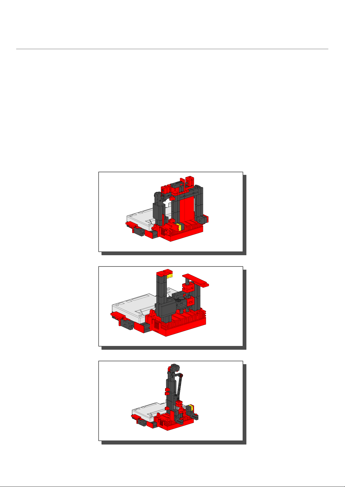
Einführungsmodelle / Introductory Models 6
Schiebetür / Sliding Door 6
Impulszähler / Pulse Counter 10
Stanze / Stamp 13

Mobile Robots:
MR1
Basismodell / Base Model 16
MR2
erkennt Hindernisse / recognizes obstacles 20
MR3
erkennt Abgründe / recognizes ledges 24
MR5
folgt einer Spur / follows a path 30
MR4
folgt einer Lichtquelle / follows a light source 27
1

Einzelteilübersicht
Spare parts list
60°
30°
31010
4x
31011
2x
31021
2x
31032
2x
31053
1x
31058
2x
31060
4x
7,5°
15°
31690
3x
31848
2x
31915
2x
31981
8x
31982
12x
32064
3x
32071
3x
32913
2x
35031
2x
35033
2x
35049
6x
35054
4x
35055
4x
35063
2x
36134
2x
36147
1x
36165
1x
36227
1x
36334
1x
36443
1x
36532
2x
31061
6x
31063
2x
31078
2x
31082
2x
31124
3x
31336
16x
31337
18x
32085
1x
32293
2x
32321
1x
32330
6x
32870
2x
32879
6x
32880
2x
35064
2x
35069
1x
35073
1x
35088
1x
35414
1x
35797
2x
35945
4x
36573
1x
36819
4x
36923
2x
36983
1x
37157
2x
37237
10x
37238
6x
31360
1x
31426
2x
31436
6x
32881
16x
32882
7x
32883
2x
35969
9x
35986
1x
36132
2x
37468
4x
37636
2x
37679
2x
2

37783
6x
38240
6x
38249
1x
38428
4x
37858
2x
37875
1x
38216
1x
Akku– / Batteriehalter
Rechargeable battery holder
Power–Block
6 Akkus oder 6 Batterien (Mignon)
Leere Akkus zum Laden aus dem Power–Block entnehmen.
Verbrauchte Batterien dem Sondermüll zuführen.
38241
5x
38242
2x
38244
2x
6 Akkus, 1,2 V Mignon, KR 15/51 AA
oder, or
6 Batterien, 1,5 V Mignon LR 06 (R6)
6 rechargeable batteries or 6 dry cells
Remove discharged battery and place in charger for recharging.
Discard spent dry cells at special waste disposal centre.
38251
2x
38258
4x
38423
7x
Batterien sind nicht Inhalt der Packung
Batteries not included
38464
2x
Spannung: 7,2 V ... / 9 V ...
Sicherung: Kurzschluß • Überlastung • Verpolung
Kabel und Stecker
Plugs and cables
2 x 30 cm
6 x 22 cm
3cm0
Voltage: 7,2 V ... / 9 V ...
Fuse protection: Short circuit • overload • reverse connection
a
4mm
b
c
5 cm0 10 cm 15 cm 20 cm 25 cm
2 x 30 cm
3cm 3cm
6 x 22 cm
3
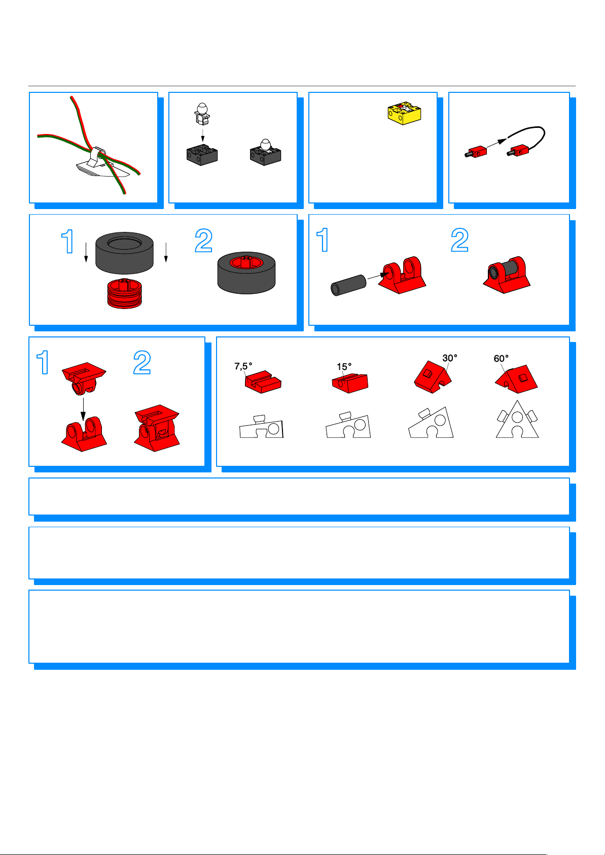
Montagehilfen und Hinweise
Assembly aids and instructions
Linsenlampe
Lens tip lamp
Fototransistor
Achtung:
Beim Anschluß auf richtige
Polung achten. Rot = +
Phototransistor
Caution:
Make sure the terminals are
connected correctly. Red = +
4x
7,5
2x
Alle elektrischen Bauteile (Sensoren, Motoren, Lampen) dürfen
ausschließlich an fischertechnik Stromversorgungen (Powerblock
oder Netzgerät) angeschlossen werden.
Alle Einzelteile, insbesondere bewegliche Teile sind falls notwendig
zu warten und zu reinigen.
Achtung
Verletzungsgefahr an Bauteilen mit funktionsbedingten scharfen
Kanten und Spitzen!
Weitere Informationen über “Mobile Robots”, das
“Intelligent Interface” und die Software LLWIN sind
auf der CD–ROM “LLWIN” (Art.–Nr. 30407) zu finden.
Diese CD–ROM enthält außerdem ein detailiertes
Beispiel zur Einführung in die fischertechnik–
Computing–Welt.
15
All electrical components (sensors, motors, lamps) may only be
connected to fischertechnik power supplies (Powerblock or
AC adapter).
All components, especially moving parts, should be maintained
and cleaned as necessary.
Caution
Be careful not to hurt yourself on components with sharp or
pointed edges!
30
60
For more information on ”Mobile Robots”, the
”Intelligent Interface”, and the ”LLWIN” software,
refer to the ”LLWIN” CD–ROM (part No. 30407).
This CD–ROM also contains a detailed introduction
to the world of fischertechnik computing.
4
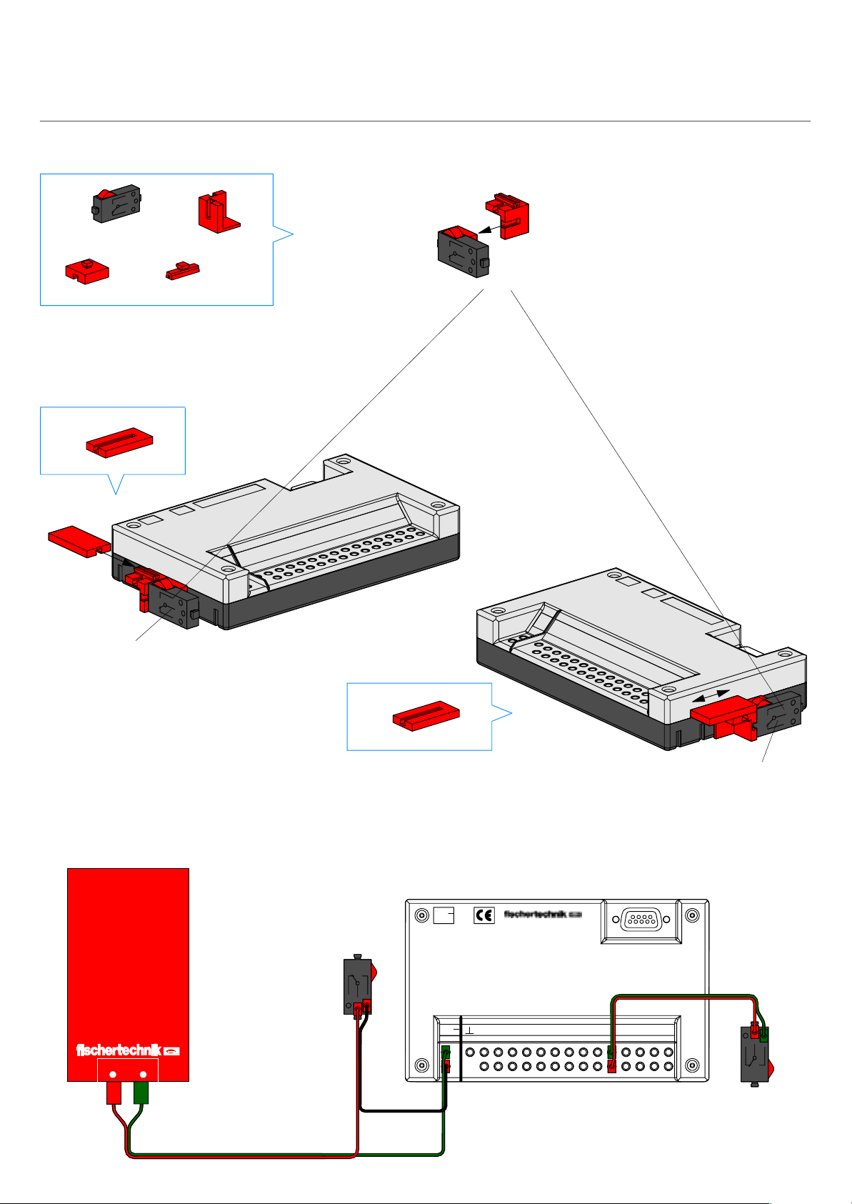
Montage Interface
Mounting Interface
1
2
2x
2x
2x
2x
2x
1x
Power on/off
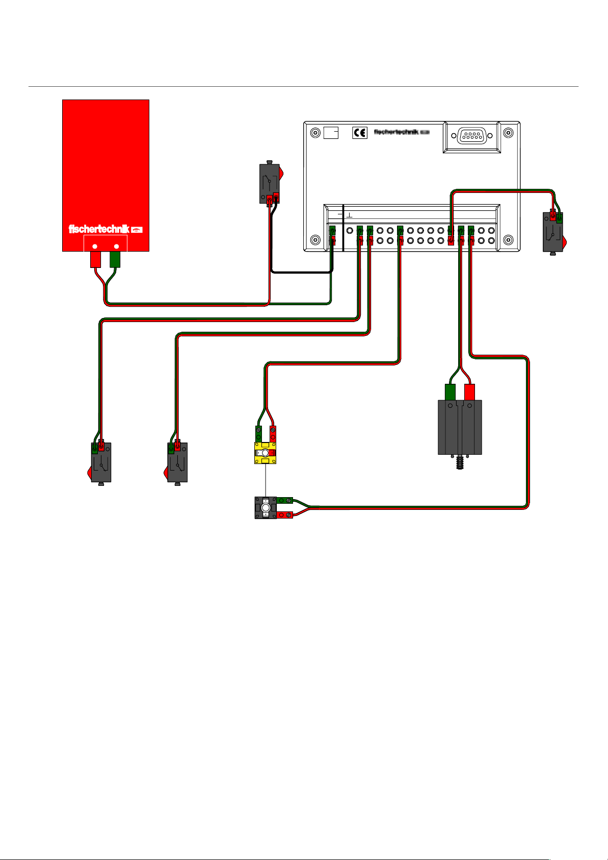
Schaltplan
Circuit diagram
Power–Block
Power
on / off
3
1x
9V...
E1 E2 EX EYE3 E4 E5 E6 M1M2M3M4
9V..
.
E8, Reset
Serielle Schnittstelle
Serial Port
22 cm
E8E7
+–
22 cm
8 cm
E8
Reset
5
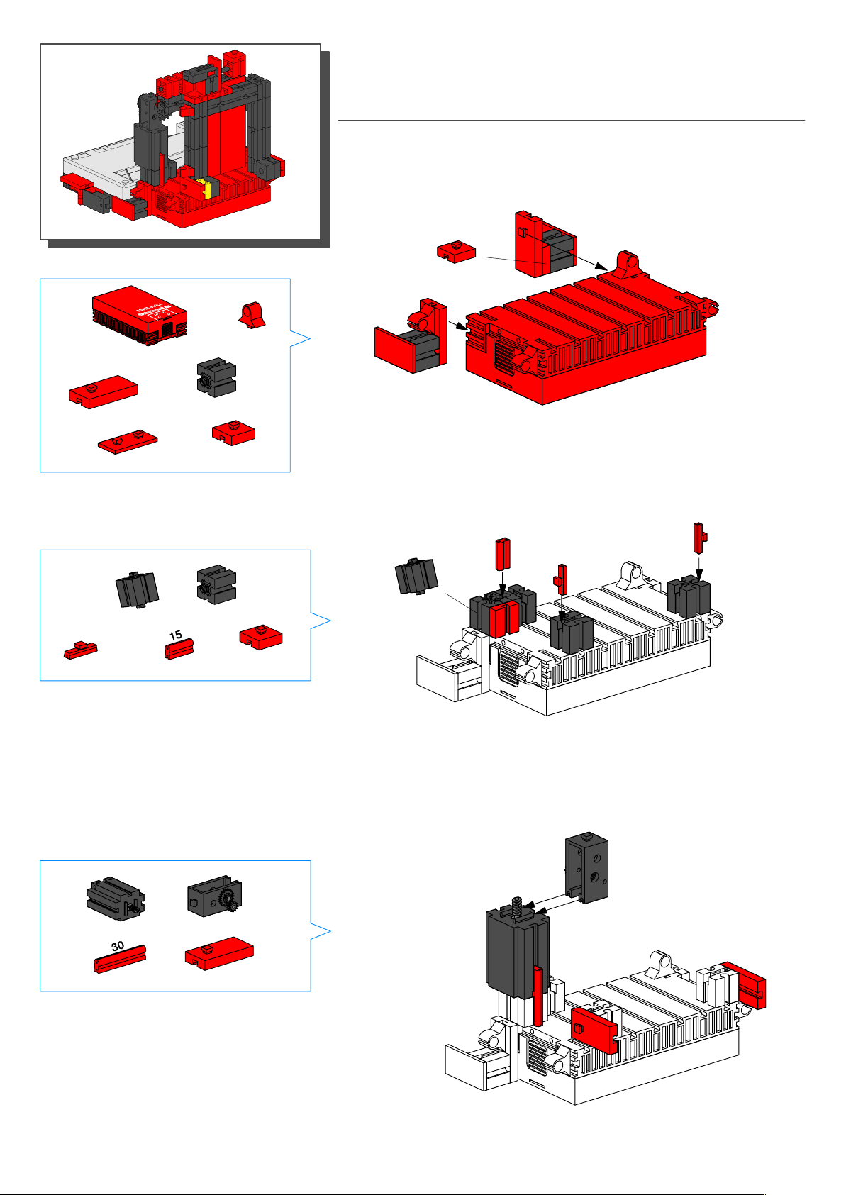
1
1x
Schiebetür
Sliding Door
4x
2
2x
2x
2x
1x
1x
2x
1x
3x
1x
3
1x
1x
6
1x
2x

4
5x
3x
1x
5
1x
1x
2x
3x
1x1x
1x
2x
1x
1x
6
2x
1x
2x
1x
2x
7

8
1x
1x
7
2x
1x
7
1x
1x
1x
98
Montage Interface Seite 5
Mounting interface Page 5
M1
1x
E1
E2
E8, Reset
M2
Power on/off
8
E3
Schaltplan
Circuit diagram
Serielle Schnittstelle
Serial port
9V...
Power–Block
+–
22 cm
22 cm
Power
on / off
30 cm
8 cm
+
22 cm
E1 E2 EX EYE3 E4 E5 E6 E7 M1M2M3M4
9V..
.
E8
22 cm
22 cm
22 cm
E8
Reset
E3
E1 E2
Beispielprogramm: tuer.mdl
Funktionsweise:
Unterbricht man die Lichtschranke, öffnet sich die Tür.
Nach einer bestimmten Zeit wird sie automatisch
wieder geschlossen. Im Passiv–Modus (siehe Soft–
warehandbuch) wird am Terminal angezeigt, ob die
Tür offen oder geschlossen ist und wie oft sie schon
geöffnet wurde.
Lichtschranke
Light bar
M2
M1
22 cm
Program example: door.mdl
Operational description:
If the light barrier is interrupted, the door opens.
After remaining open for a specified period of time,
the door closes. In the passive mode (refer to the
software manual), the terminal indicates whether
the door is open or closed, and how often it has
been opened.
9
 Loading...