

Page 1

Page 2
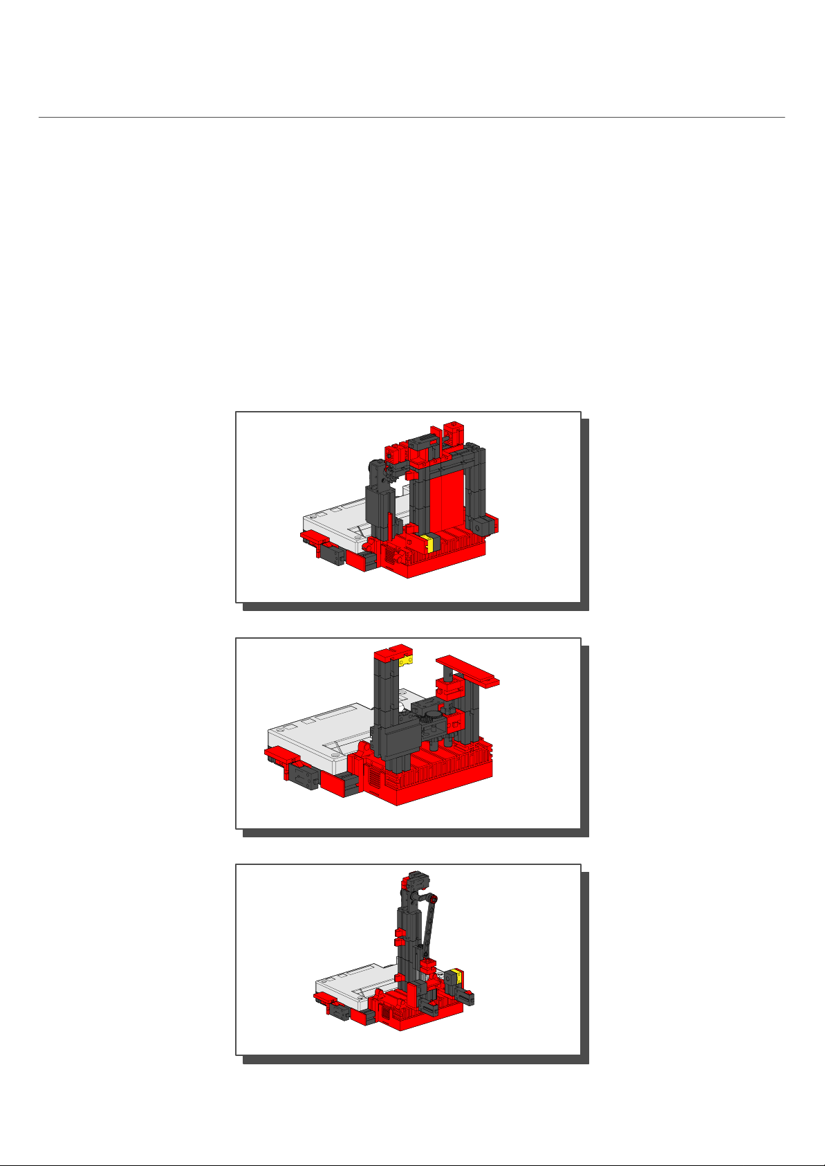
Inhalt
Contents
Einzelteilübersicht / Spare parts list 2
Akku–, Batteriehalter / Rechargeable battery holder 3
Kabel und Stecker / Plugs and cables 3
Montagehilfen und Hinweise / Assembly aids and instructions 4
Montage Interface / Mounting interface 5
Einführungsmodelle / Introductory Models 6
Schiebetür / Sliding Door 6
Impulszähler / Pulse Counter 10
Stanze / Stamp 13
Page 3

Mobile Robots:
MR1
Basismodell / Base Model 16
MR2
erkennt Hindernisse / recognizes obstacles 20
MR3
erkennt Abgründe / recognizes ledges 24
MR5
folgt einer Spur / follows a path 30
MR4
folgt einer Lichtquelle / follows a light source 27
1
Page 4

Einzelteilübersicht
Spare parts list
60°
30°
31010
4x
31011
2x
31021
2x
31032
2x
31053
1x
31058
2x
31060
4x
7,5°
15°
31690
3x
31848
2x
31915
2x
31981
8x
31982
12x
32064
3x
32071
3x
32913
2x
35031
2x
35033
2x
35049
6x
35054
4x
35055
4x
35063
2x
36134
2x
36147
1x
36165
1x
36227
1x
36334
1x
36443
1x
36532
2x
31061
6x
31063
2x
31078
2x
31082
2x
31124
3x
31336
16x
31337
18x
32085
1x
32293
2x
32321
1x
32330
6x
32870
2x
32879
6x
32880
2x
35064
2x
35069
1x
35073
1x
35088
1x
35414
1x
35797
2x
35945
4x
36573
1x
36819
4x
36923
2x
36983
1x
37157
2x
37237
10x
37238
6x
31360
1x
31426
2x
31436
6x
32881
16x
32882
7x
32883
2x
35969
9x
35986
1x
36132
2x
37468
4x
37636
2x
37679
2x
2
Page 5

37783
6x
38240
6x
38249
1x
38428
4x
37858
2x
37875
1x
38216
1x
Akku– / Batteriehalter
Rechargeable battery holder
Power–Block
6 Akkus oder 6 Batterien (Mignon)
Leere Akkus zum Laden aus dem Power–Block entnehmen.
Verbrauchte Batterien dem Sondermüll zuführen.
38241
5x
38242
2x
38244
2x
6 Akkus, 1,2 V Mignon, KR 15/51 AA
oder, or
6 Batterien, 1,5 V Mignon LR 06 (R6)
6 rechargeable batteries or 6 dry cells
Remove discharged battery and place in charger for recharging.
Discard spent dry cells at special waste disposal centre.
38251
2x
38258
4x
38423
7x
Batterien sind nicht Inhalt der Packung
Batteries not included
38464
2x
Spannung: 7,2 V ... / 9 V ...
Sicherung: Kurzschluß • Überlastung • Verpolung
Kabel und Stecker
Plugs and cables
2 x 30 cm
6 x 22 cm
3cm0
Voltage: 7,2 V ... / 9 V ...
Fuse protection: Short circuit • overload • reverse connection
a
4mm
b
c
5 cm0 10 cm 15 cm 20 cm 25 cm
2 x 30 cm
3cm 3cm
6 x 22 cm
3
Page 6
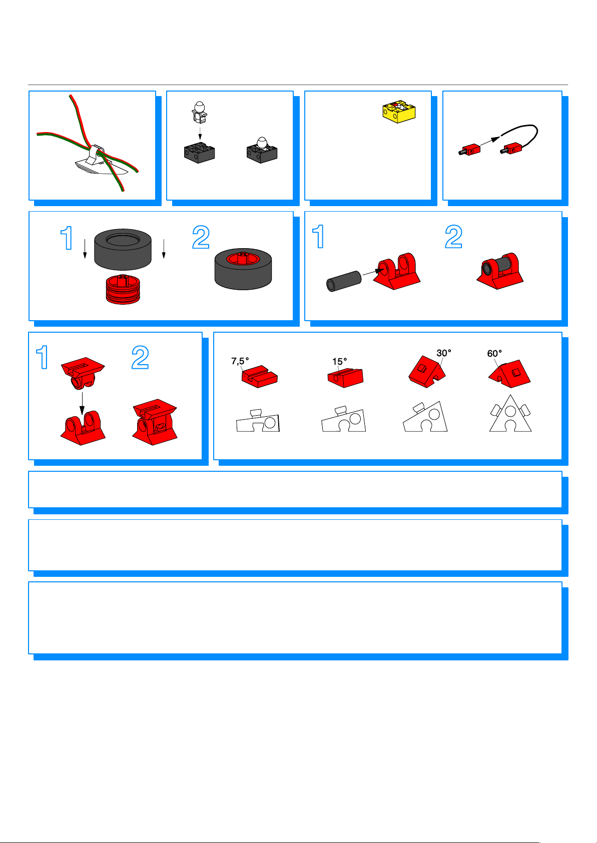
Montagehilfen und Hinweise
Assembly aids and instructions
Linsenlampe
Lens tip lamp
Fototransistor
Achtung:
Beim Anschluß auf richtige
Polung achten. Rot = +
Phototransistor
Caution:
Make sure the terminals are
connected correctly. Red = +
4x
7,5
2x
Alle elektrischen Bauteile (Sensoren, Motoren, Lampen) dürfen
ausschließlich an fischertechnik Stromversorgungen (Powerblock
oder Netzgerät) angeschlossen werden.
Alle Einzelteile, insbesondere bewegliche Teile sind falls notwendig
zu warten und zu reinigen.
Achtung
Verletzungsgefahr an Bauteilen mit funktionsbedingten scharfen
Kanten und Spitzen!
Weitere Informationen über “Mobile Robots”, das
“Intelligent Interface” und die Software LLWIN sind
auf der CD–ROM “LLWIN” (Art.–Nr. 30407) zu finden.
Diese CD–ROM enthält außerdem ein detailiertes
Beispiel zur Einführung in die fischertechnik–
Computing–Welt.
15
All electrical components (sensors, motors, lamps) may only be
connected to fischertechnik power supplies (Powerblock or
AC adapter).
All components, especially moving parts, should be maintained
and cleaned as necessary.
Caution
Be careful not to hurt yourself on components with sharp or
pointed edges!
30
60
For more information on ”Mobile Robots”, the
”Intelligent Interface”, and the ”LLWIN” software,
refer to the ”LLWIN” CD–ROM (part No. 30407).
This CD–ROM also contains a detailed introduction
to the world of fischertechnik computing.
4
Page 7
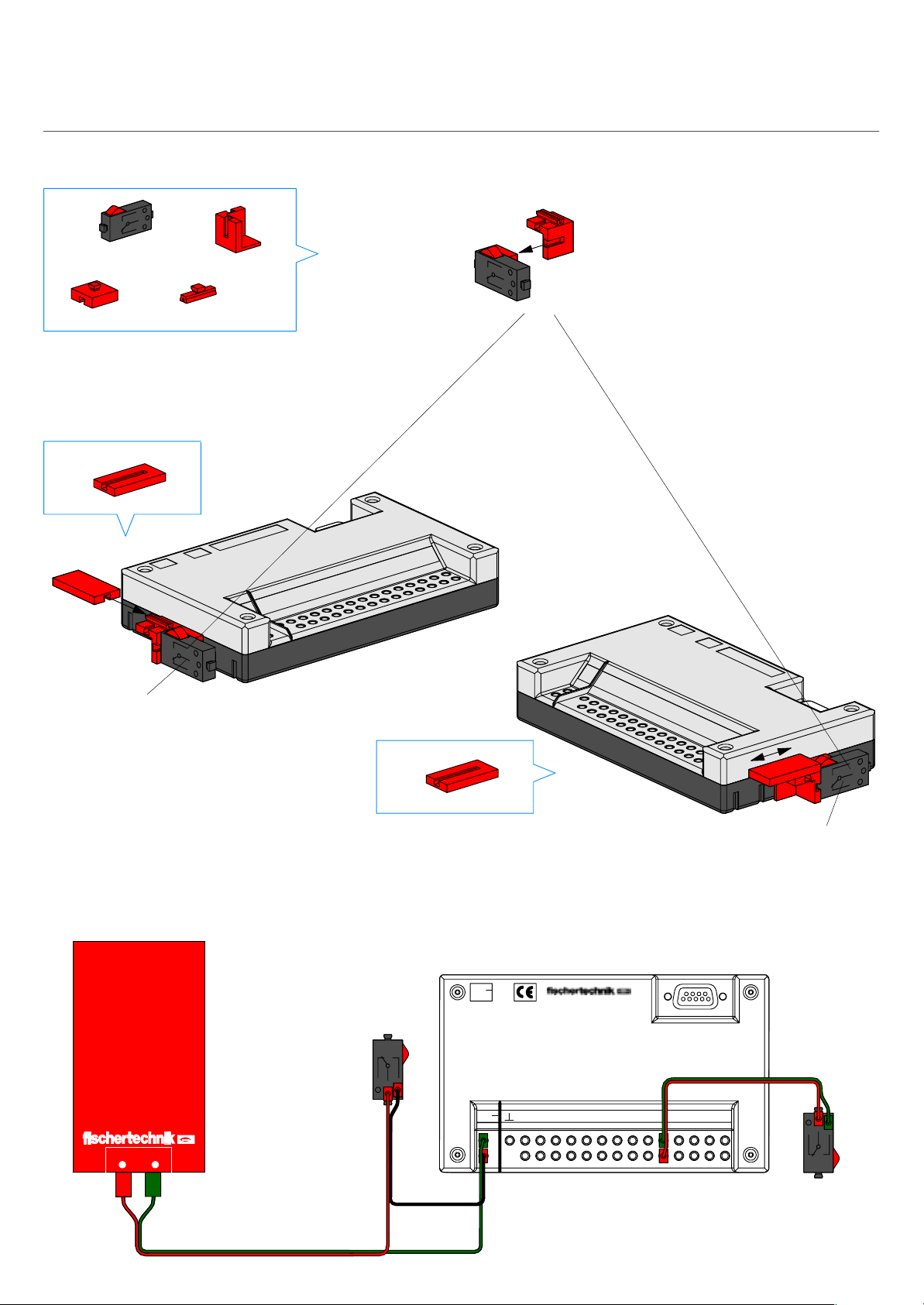
Montage Interface
Mounting Interface
1
2
2x
2x
2x
2x
2x
1x
Power on/off
Schaltplan
Circuit diagram
Power–Block
Power
on / off
3
1x
9V...
E1 E2 EX EYE3 E4 E5 E6 M1M2M3M4
9V..
.
E8, Reset
Serielle Schnittstelle
Serial Port
22 cm
E8E7
+–
22 cm
8 cm
E8
Reset
5
Page 8
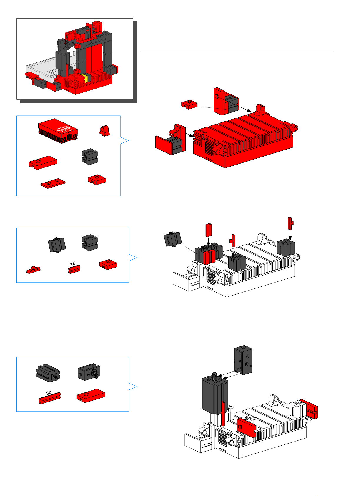
1
1x
Schiebetür
Sliding Door
4x
2
2x
2x
2x
1x
1x
2x
1x
3x
1x
3
1x
1x
6
1x
2x
Page 9

4
5x
3x
1x
5
1x
1x
2x
3x
1x1x
1x
2x
1x
1x
6
2x
1x
2x
1x
2x
7
Page 10

8
1x
1x
7
2x
1x
7
1x
1x
1x
98
Montage Interface Seite 5
Mounting interface Page 5
M1
1x
E1
E2
E8, Reset
M2
Power on/off
8
E3
Page 11
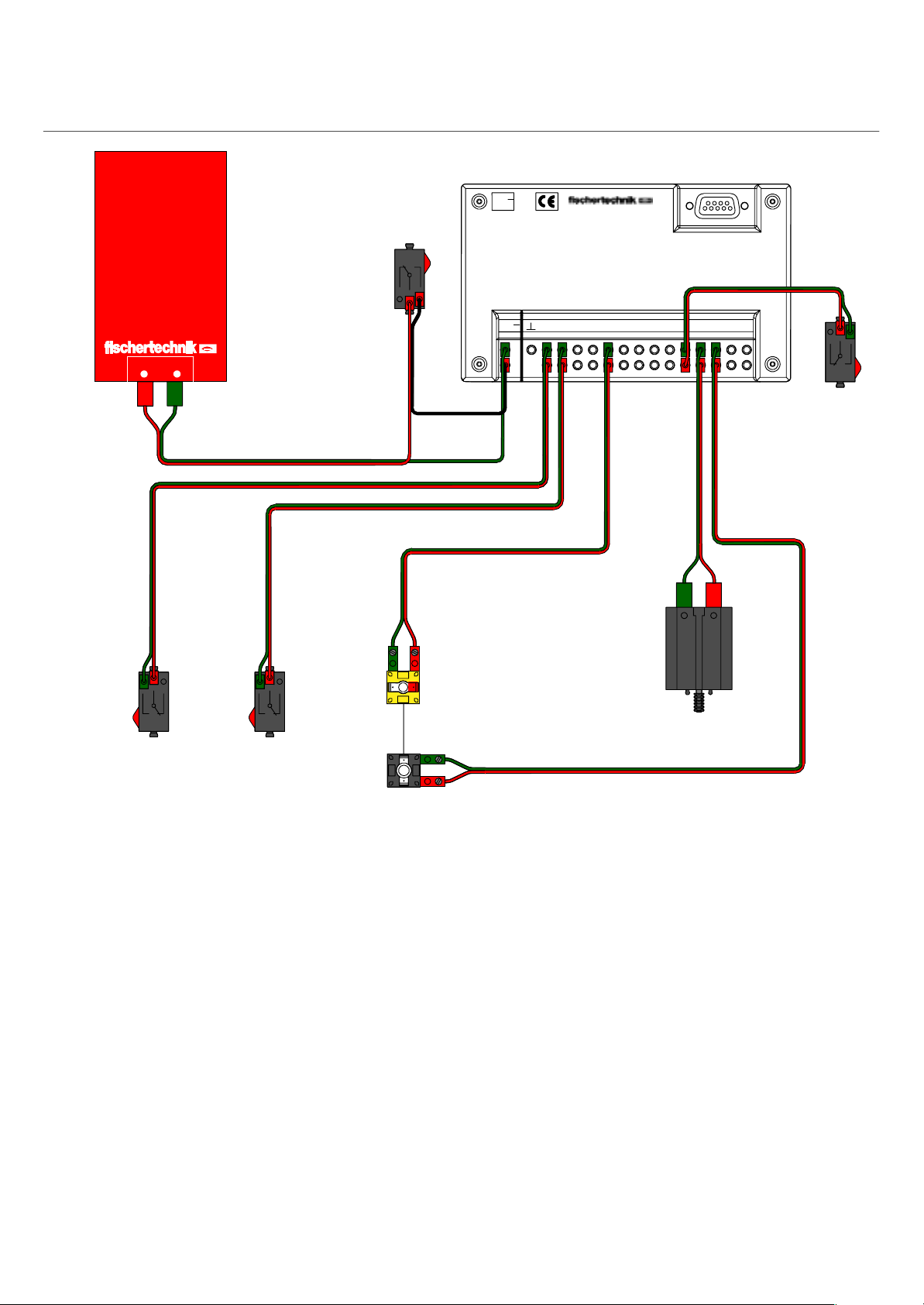
Schaltplan
Circuit diagram
Serielle Schnittstelle
Serial port
9V...
Power–Block
+–
22 cm
22 cm
Power
on / off
30 cm
8 cm
+
22 cm
E1 E2 EX EYE3 E4 E5 E6 E7 M1M2M3M4
9V..
.
E8
22 cm
22 cm
22 cm
E8
Reset
E3
E1 E2
Beispielprogramm: tuer.mdl
Funktionsweise:
Unterbricht man die Lichtschranke, öffnet sich die Tür.
Nach einer bestimmten Zeit wird sie automatisch
wieder geschlossen. Im Passiv–Modus (siehe Soft–
warehandbuch) wird am Terminal angezeigt, ob die
Tür offen oder geschlossen ist und wie oft sie schon
geöffnet wurde.
Lichtschranke
Light bar
M2
M1
22 cm
Program example: door.mdl
Operational description:
If the light barrier is interrupted, the door opens.
After remaining open for a specified period of time,
the door closes. In the passive mode (refer to the
software manual), the terminal indicates whether
the door is open or closed, and how often it has
been opened.
9
Page 12
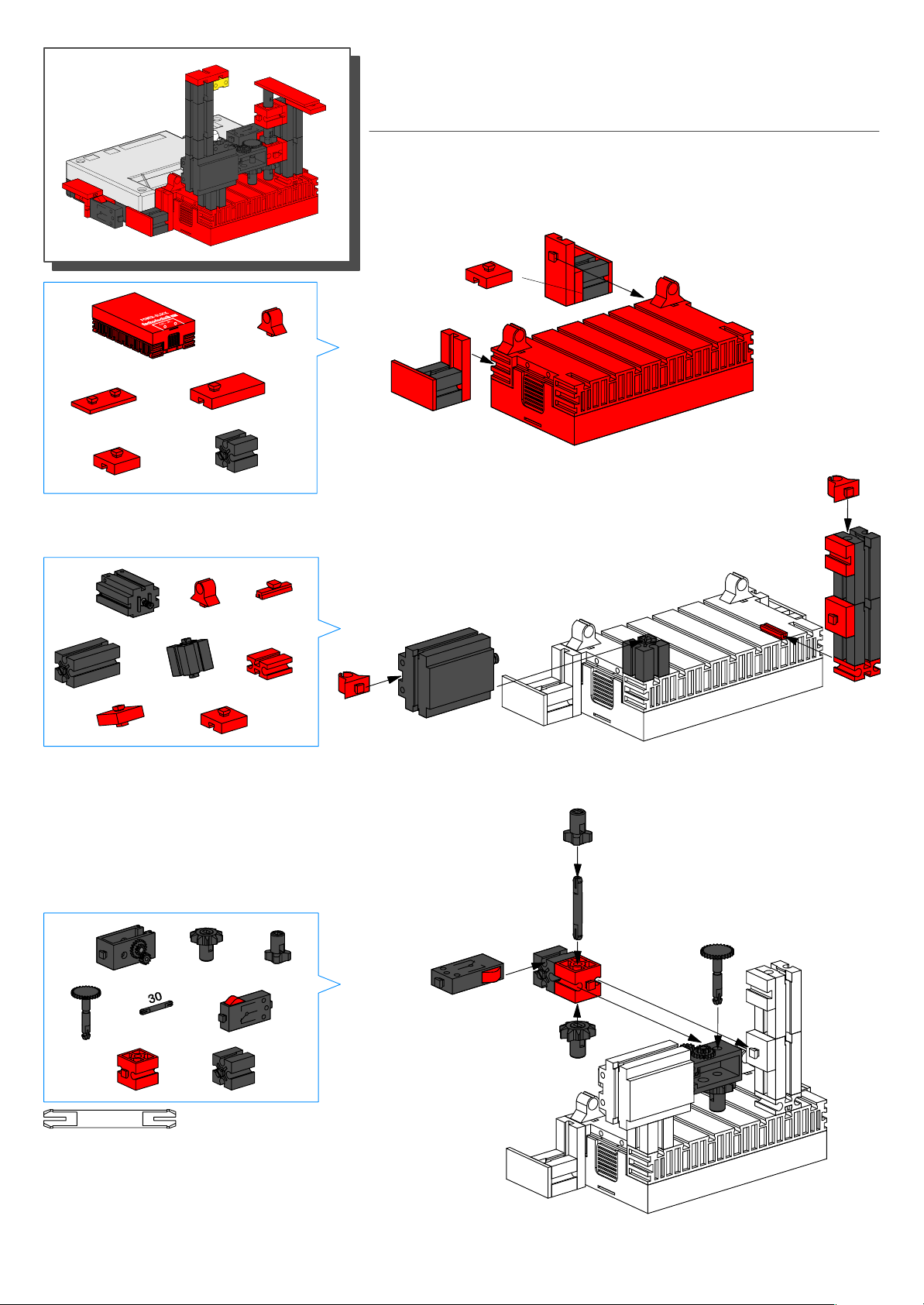
1
Impulszähler
Pulse Counter
2x
1x
2
2x
2x
1x
1x
1x
1x
2x
2x
1x
2x
1x
1x
10
3
1x
30
1x
1x
1x
2x
1x
1x
1x
Page 13
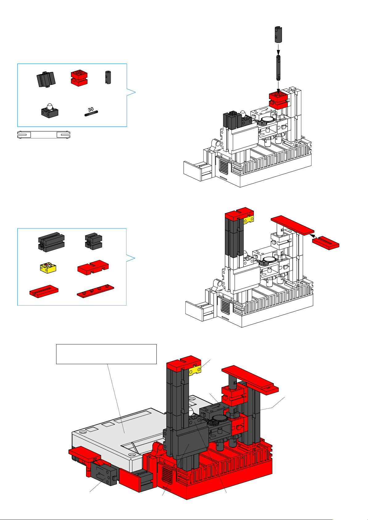
4
5
30
1x
1x 1x
1x 1x
1x
1x
1x
1x
1x
1x
Montage Interface Seite 5
Mounting interface Page 5
E2
E1
E8, Reset
Power on/off
M1
M2
11
Page 14
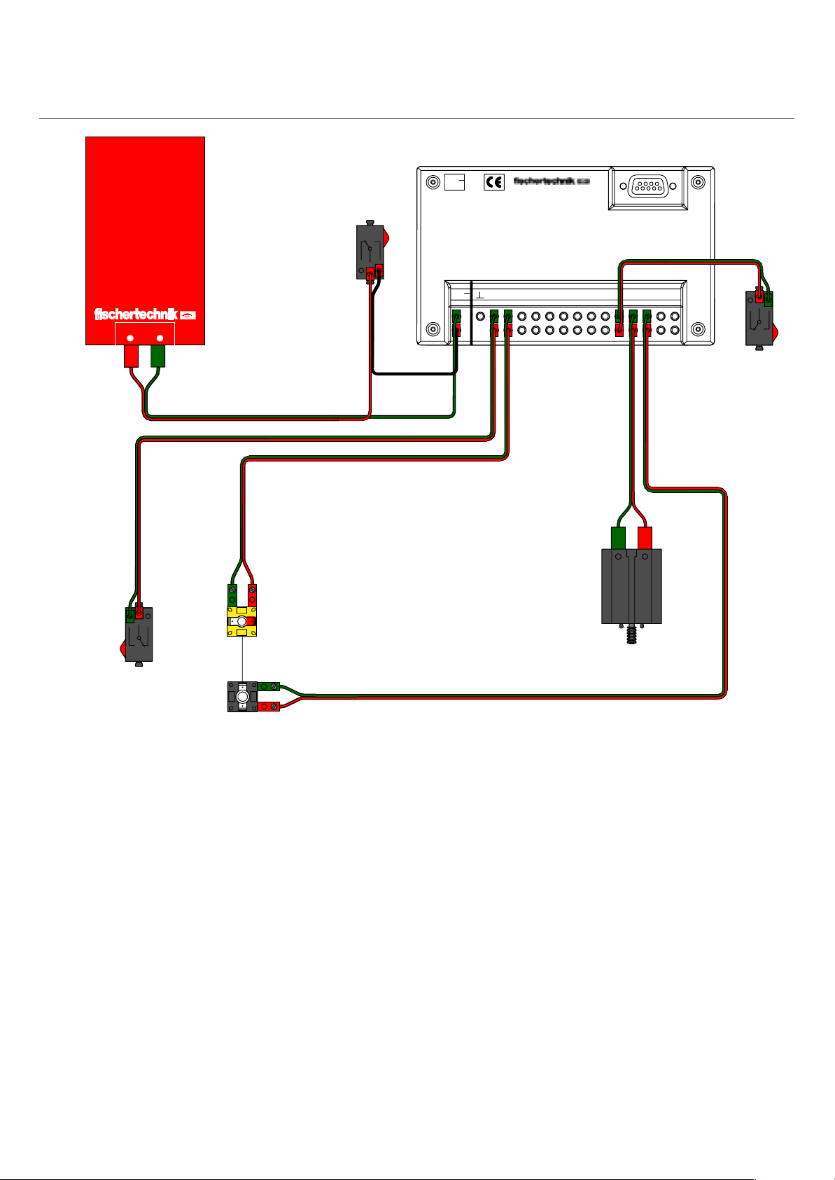
Schaltplan
Circuit diagram
Power
on / off
9V...
Serielle Schnittstelle
Serial Port
22 cm
22 cm
Power–Block
+–
E1
22 cm
22 cm
+
E2
Lichtschranke
Light bar
30 cm
8 cm
E1 E2 EX EYE3 E4 E5 E6 E7 M1M2M3M4
9V..
.
22 cm
E8
E8
Reset
22 cm
M1
M2
Beispielprogramm: impuls.mdl
Funktionsweise
Die von Motor M1 angetriebene rotierende Bauplatte
unterbricht bei jeder Umdrehung einmal die Licht–
schranke. Gleichzeitig zählt der Taster an E1 über
das Impulsrad acht Impulse pro Umdrehung. Nach
zehn Umdrehungen stoppt der Motor. Die gezählten
Impulse werden im Passiv–Modus am Bildschirm mit
dem Softwarebaustein Terminal angezeigt.
Dieser Versuch zeigt, welche Auflösung beim Zählen
von Impulsen mit einem Impulsrad erreichbar ist.
Mit den Impulsrädern werden bei den mobilen Robotern
die zurückgelegten Wegstrecken “gemessen”.
Program example: pulse.mdl
Operational description:
Once every rotation, the turning base plate driven by
motor M1 interrupts the light barrier. At the same time,
the feeler on E1 counts eight pulses per rotation from
the pulse wheel. The motor stops after ten rotations of
the plate. The number of pulses counted is displayed
on the screen by the terminal software building block
in the passive mode.
This test shows the resolution that can be achieved by
counting pulses with a pulse wheel.
Pulse wheels are used by mobile robots to ”measure”
the distances they have traveled.
12
Page 15
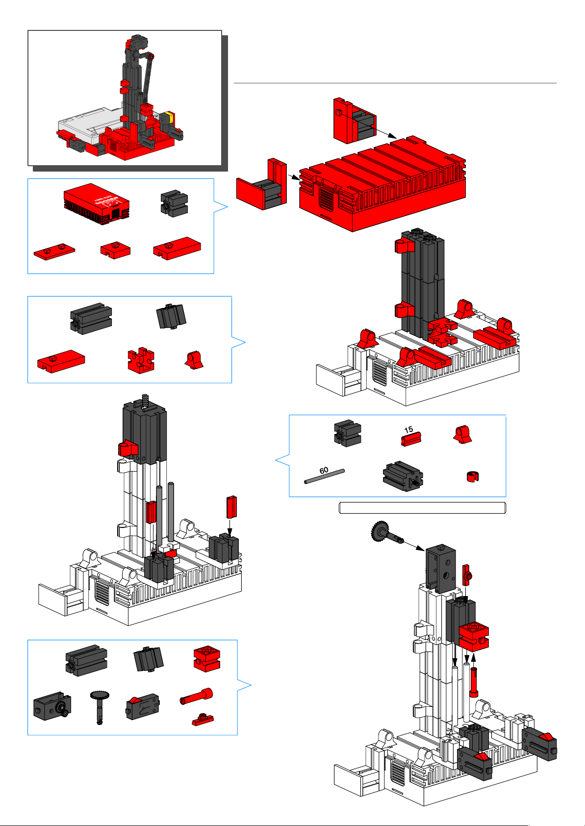
1
1x
Stanze
Stamp
2x
2
2x 2x
2x
4x
1x
2x
1x
6x
3
2x
2x
60
2x
1x
1x
2x
4
1x
1x
1x
2x
1x
1x
1x
1x
13
Page 16
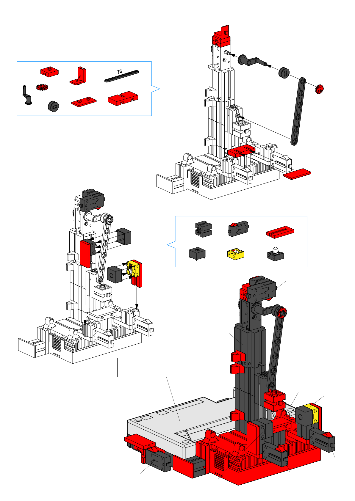
5
1x
2x
1x
1x
1x
1x
1x
1x
6
2x
1x
1x
1x
2x
1x
Montage Interface Seite 5
Mounting interface Page 5
M1
E1
E8, Reset
E2
14
Power on/off
E4
E3
M1
Page 17
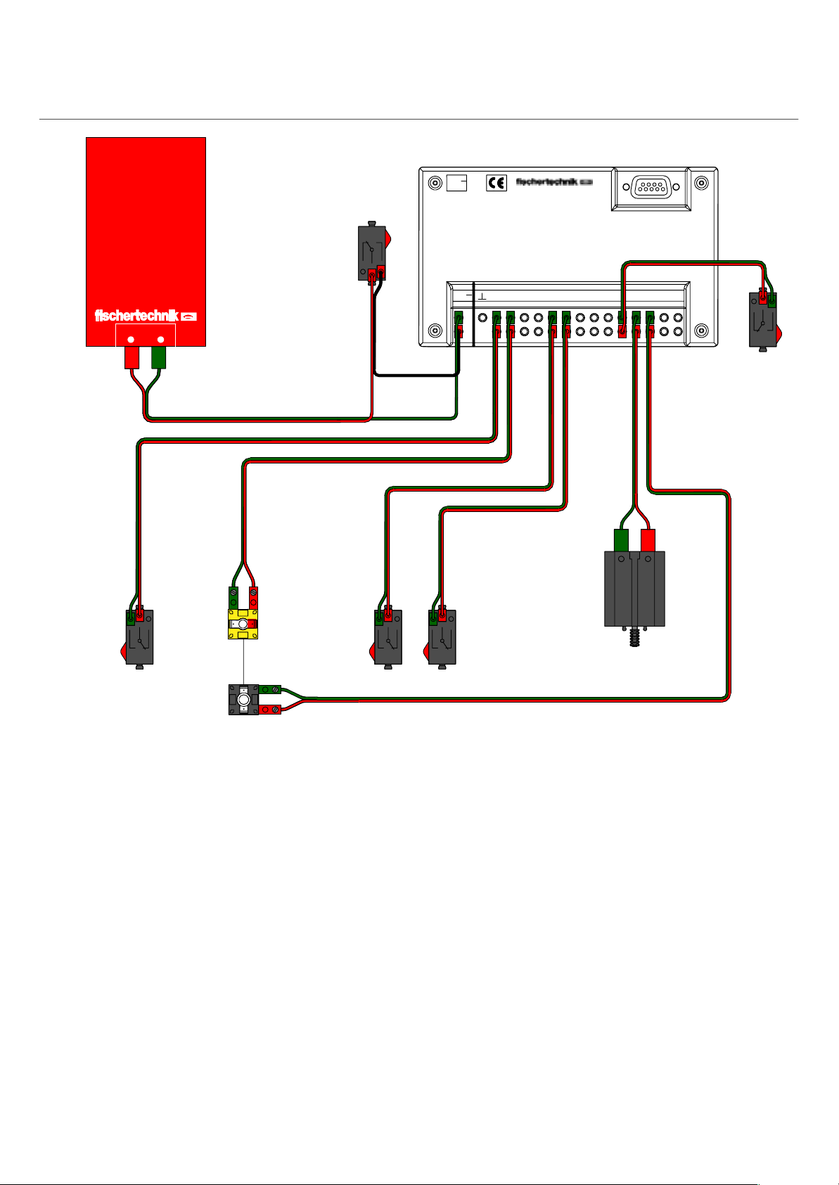
Schaltplan
Circuit diagram
Power
on / off
9V...
Serielle Schnittstelle
Serial port
22 cm
22 cm
Power–Block
+–
E1
22 cm
30 cm
+
E2
Lichtschranke
Light bar
30 cm
8 cm
E3 E4
E1 E2 EX EYE3 E4 E5 E6 E7 M1M2M3M4
9V..
.
22 cm
22 cm
22 cm
E8
E8
Reset
22 cm
M1
M2
Beispielprogramm: stanze.mdl
Funktionsweise:
Durch gleichzeitiges Drücken der Taster E3 und E4 wird
die Maschine in Gang gesetzt und führt eine bestimmte
Anzahl von Hüben aus. Unterbricht man die Licht–
schranke, stoppt die Maschine und muß neu gestartet
werden. Im Passiv–Modus werden am Terminal die Anzahl
der Hübe und die Zahl der Durchgänge angezeigt.
Program example: stamp.mdl
Operational description:
Simultaneously pressing switches E3 and E4 puts
the machine in gear and causes it to carry out a
specific number of strokes.If the light barrier is
broken, the machine stops and must be restarted.
The number of strokes and the number of completed
runs are shown on the terminal in the passive mode.
15
Page 18
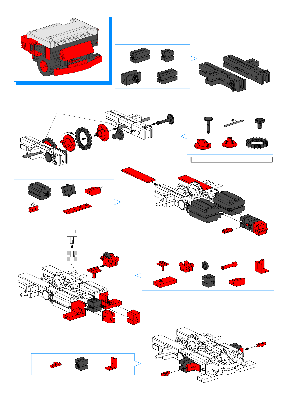
MR 1
Basismodell
Base Model
1
2x
2x
Auf genügend Spiel in den Lagern achten
Make sure the bearings have enough play
3
2x
2x
2x
2x
2x
15°
2x
2x
2
2x
60
2x
2x
2x
2x2x
16
5
2x
2x
2x
4
1x 1x
2x
1x
1x
1x
4x
15°
2x
Page 19
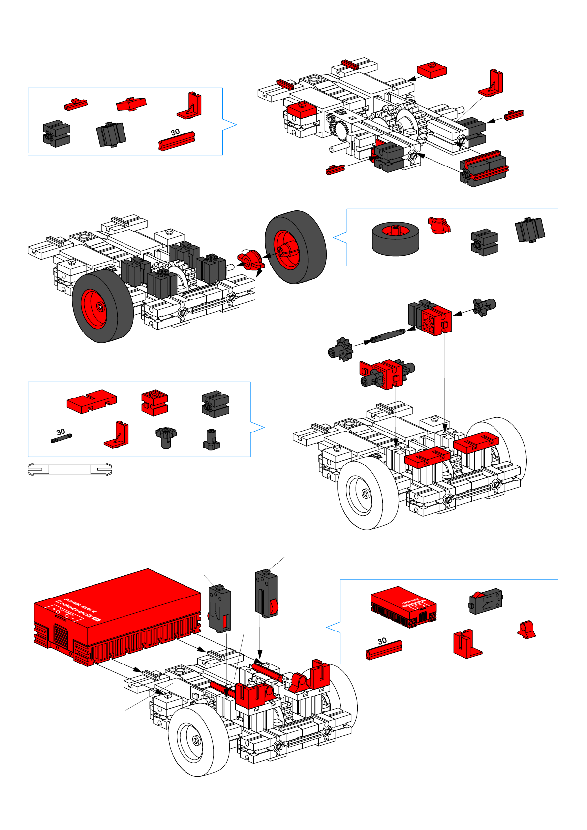
6
4x
2x
2x
8
3x
2x
1x
2x
2x
1x
7
2x
2x
2x
2x
30
2x
M1
1x
2x
E1
2x
M2
E2
9
2x
2x
1x
2x
2x
17
Page 20
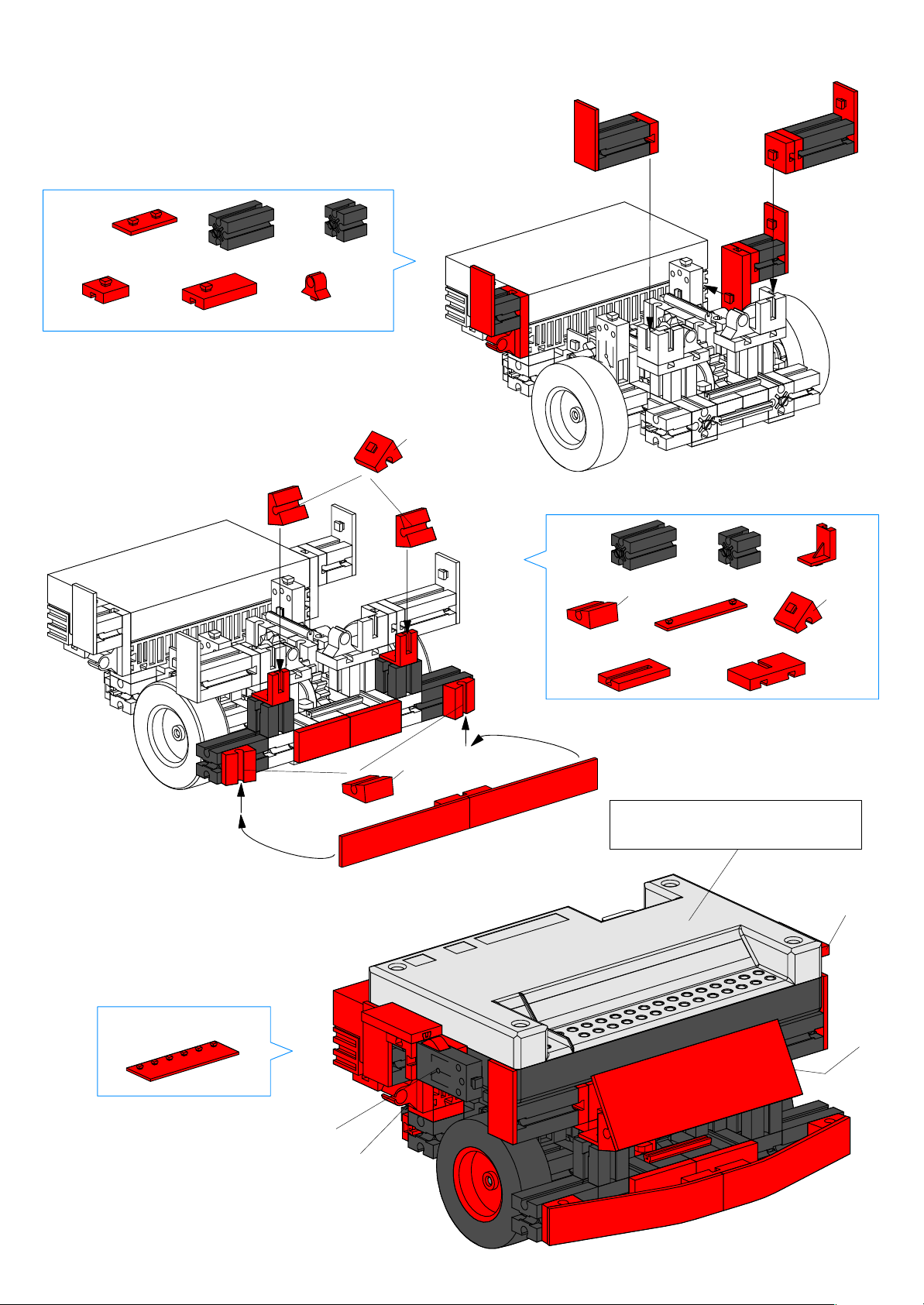
10
4x
2x
2x
4x
2x
1x
30°
11
2x
15°
2x
2x
2x
2x
2x
30°
2x
1x
12
15°
Montage Interface Seite 5
Mounting interface Page 5
E8, Reset
M2/E2
1x
Power on/off
M1/E1
18
Page 21
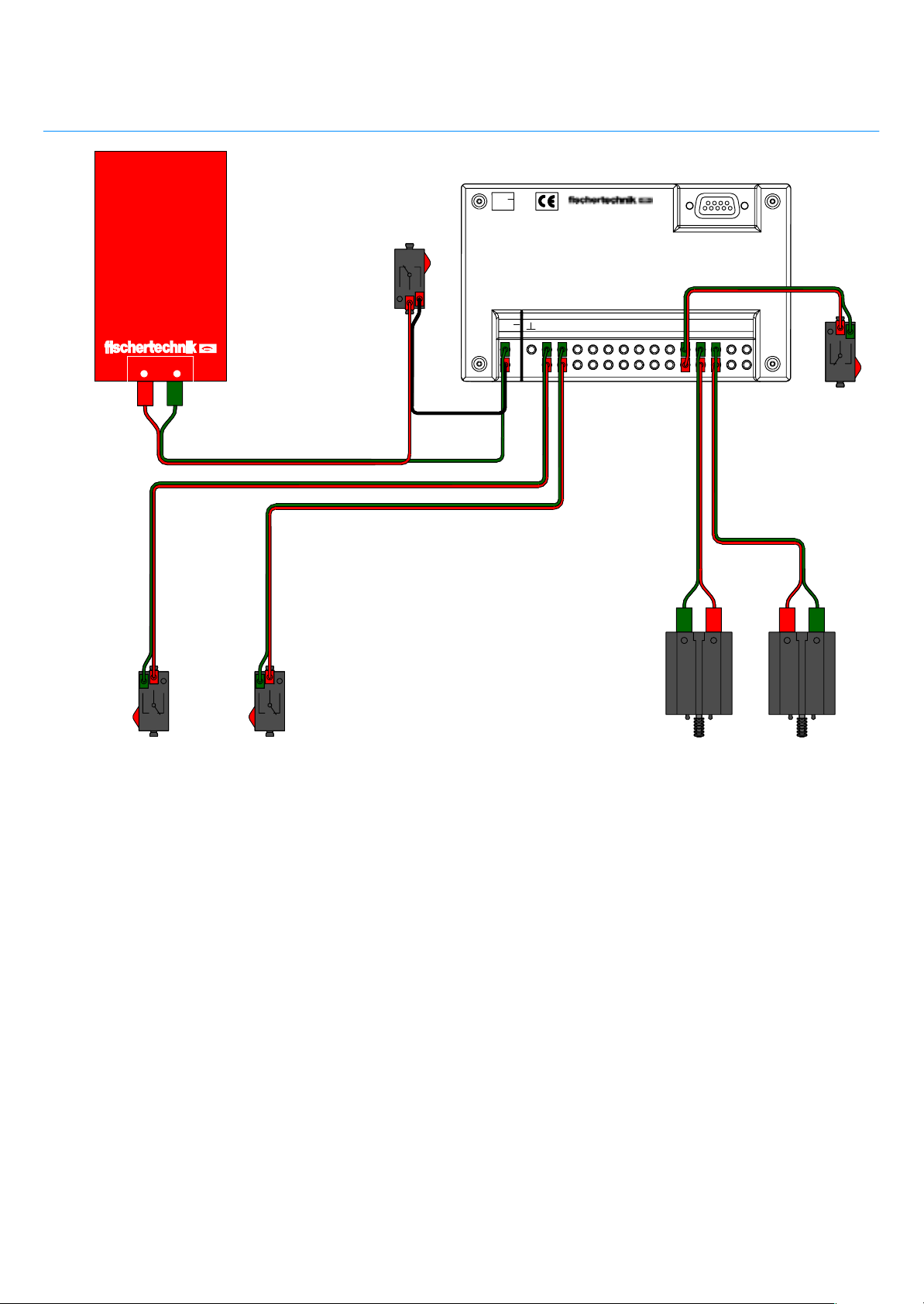
Schaltplan
Circuit diagram
Serielle Schnittstelle
Serial port
9V...
Power–Block
+–
22 cm
22 cm
Power
on / off
22 cm
8 cm
E1 E2 EX EYE3 E4 E5 E6 E7 M1M2M3M4
9V..
.
E8
30 cm
30 cm
22 cm
22 cm
E8
Reset
E1 E2 M1
Beispielprogramm: mr1.mdl
Funktionsweise:
MR1 ist in der Lage, definierte Strecken vorwärts,
rückwärts, nach links und rechts zurückzulegen.
Er besitzt jedoch keine Sensoren um beispiels–
weise Hindernisse zu erkennen.
Dieses Modell bildet den Einstieg in die Welt der
mobilen fischertechnik Roboter.
M2
Program example: mr1.mdl
Operational description:
MR1 is able to travel for designated distances
forwards, backwards, to the left, and to the right.
It is not, however, equipped with any sensors to,
for example, recognize obstacles.
This model offers an introduction into the world of
fischertechnik’s mobile robots.
19
Page 22
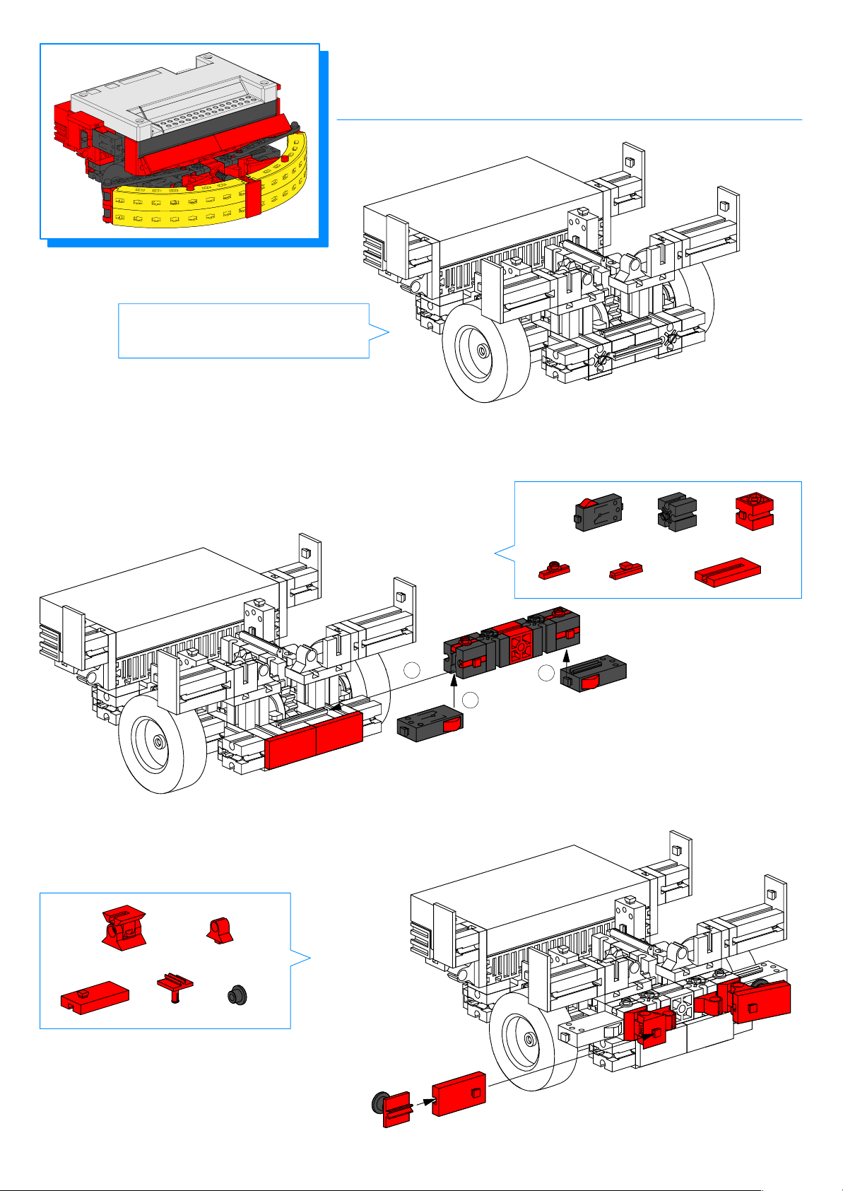
MR 2
erkennt Hindernisse
recognizes obstacles
1–10
Seite
Page
16 – 18
16 – 18
11
2x
2x
2
1
1
2x
4x
1x
2x
20
12
2x
2x
2x
2x
2x
Page 23
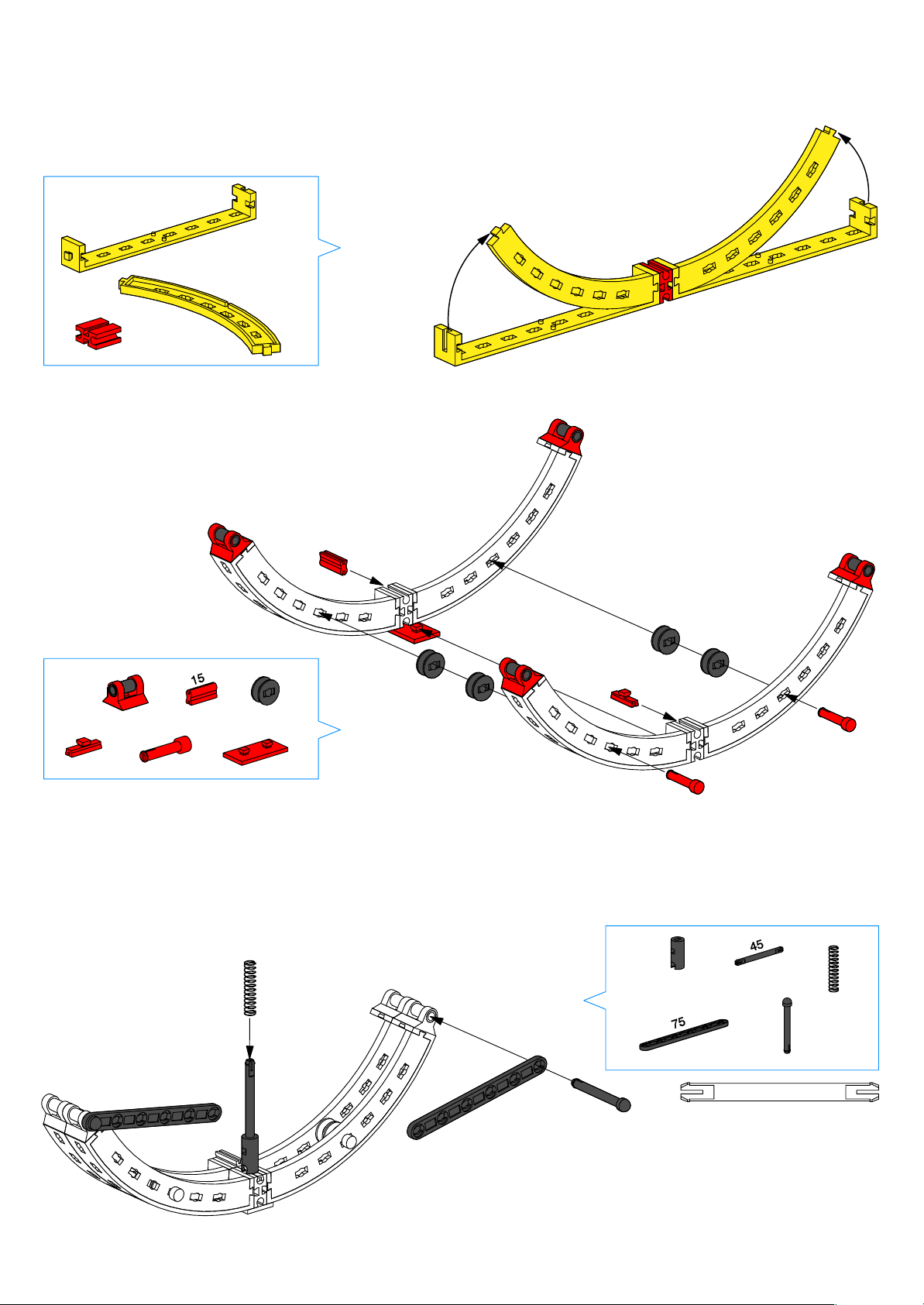
13
4x
2x
14
1x
2x
4x
2x
1x
4x
4x
1x
15
1x
1x
1x
2x
2x
45
21
Page 24
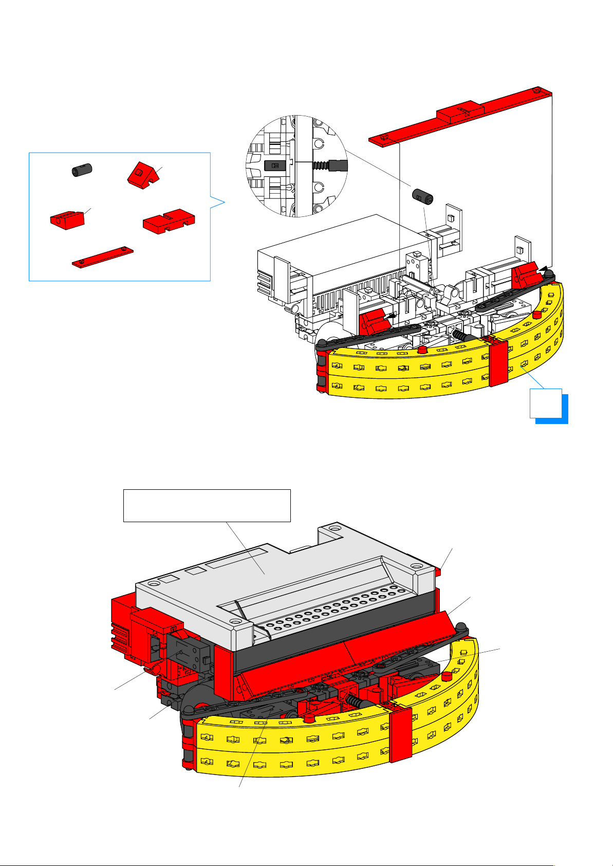
16
30°
1x
2x
15°
2x
1x
2x
15
Montage Interface Seite 5
Mounting interface Page 5
Power on/off
E8, Reset
M2/E2
E4
M1/E1
E3
22
Page 25
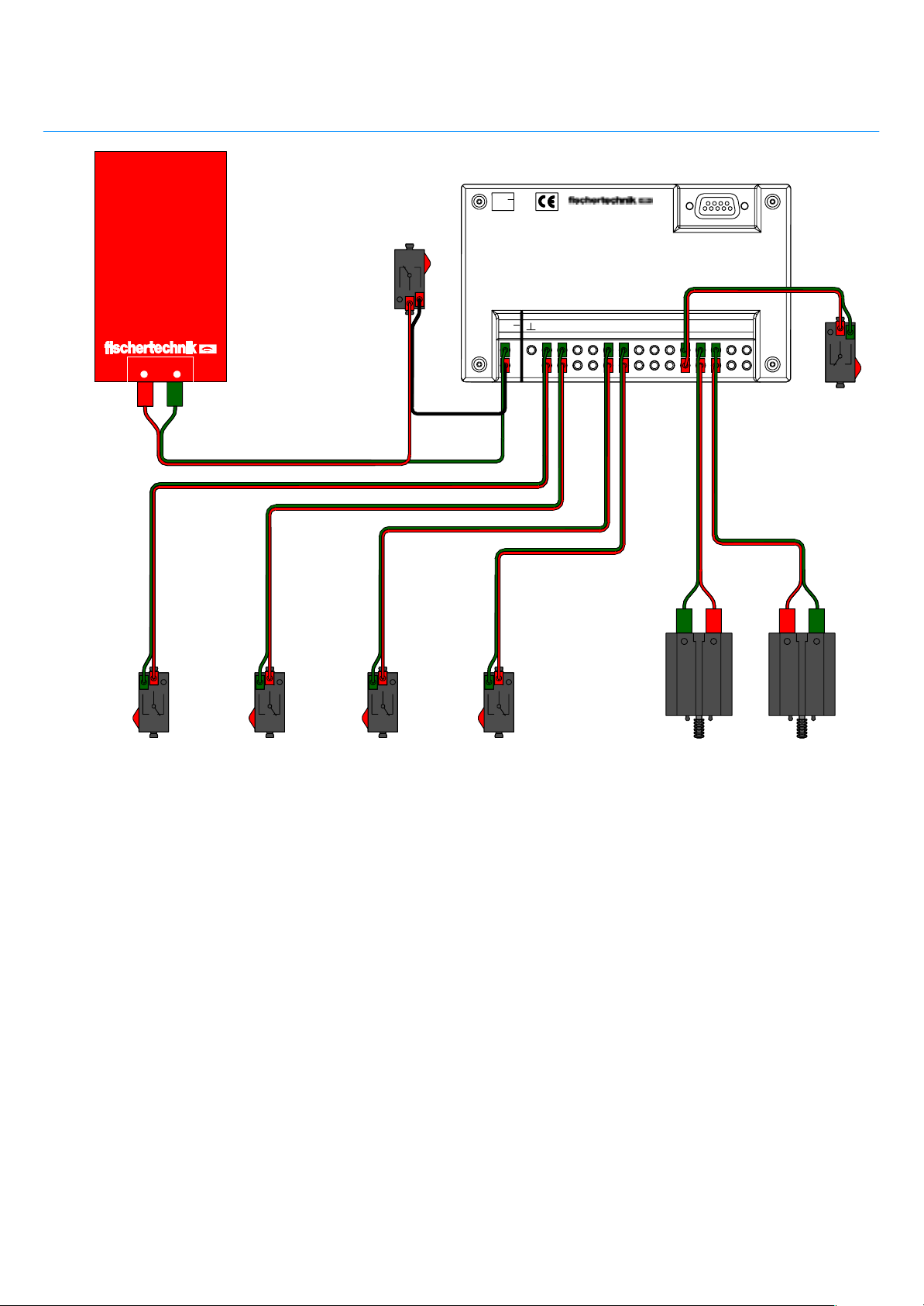
Schaltplan
Circuit diagram
Serielle Schnittstelle
Serial port
9V...
Power
on / off
Power–Block
+–
22 cm
22 cm 22 cm
22 cm
8 cm
22 cm
E1 E2 EX EYE3 E4 E5 E6 E7 M1M2M3M4
9V..
.
E8
30 cm
30 cm
22 cm
22 cm
E8
Reset
E1 E2
Beispielprogramm: mr2.mdl
Funktionsweise:
MR2 kann, sobald er mit seiner Stoßstange auf ein
Hindernis trifft, diesem Hindernis ausweichen. Die
Stoßstange löst zwei Taster, E3 und E4, aus. Das
Modell weicht dann nach rechts oder links aus, je
nachdem welcher der beiden Taster gedrückt wird.
E3 E4
Program example: mr2.mdl
M1
M2
Operational description:
As soon as its bumper runs into an obstacle, MR2
can attempt to circumvent it. The bumper activates
two switches, E3 and E4. The model then moves
either to the right or the left, depending on which
switch was activated.
23
Page 26
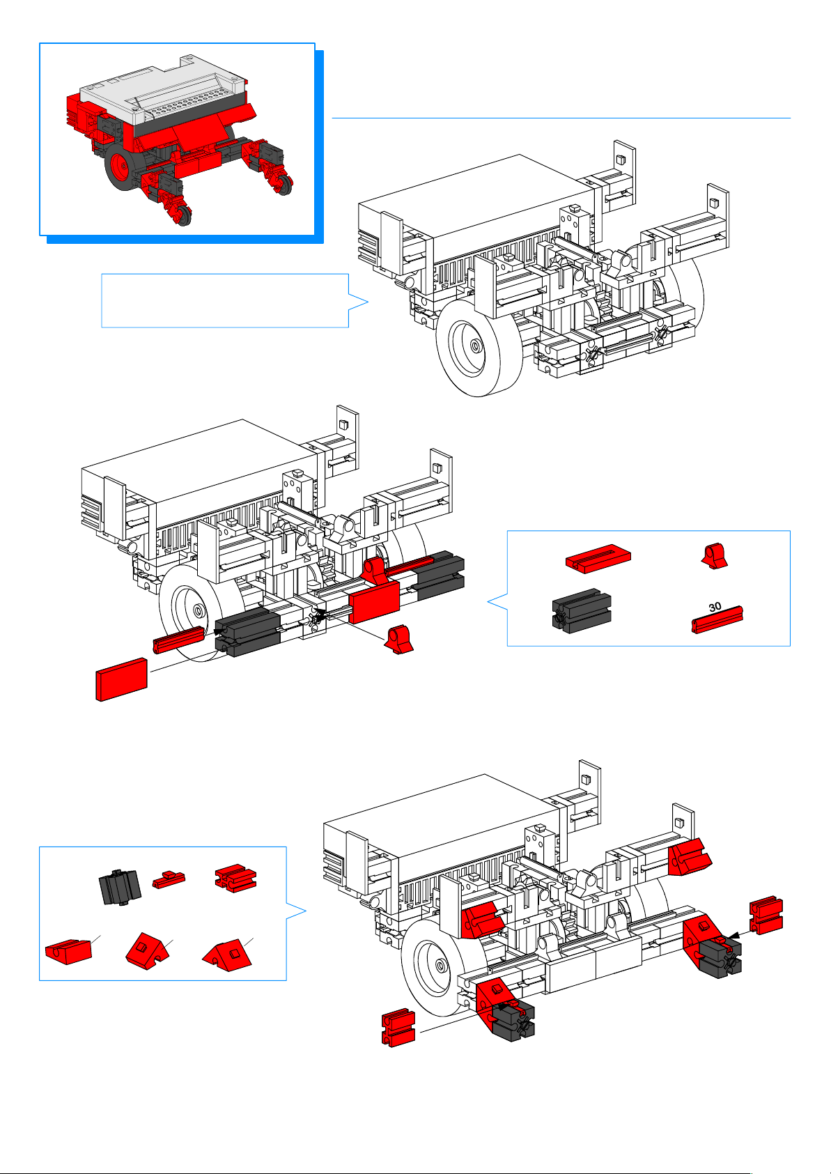
MR3
erkennt Abgründe
recognizes ledges
1–10
Seite
Page
16 – 18
16 – 18
11
2x
2x
2x
2x
24
12
2x
15°
2x
30°
2x
2x
2x
60°
4x
Page 27
13
2x
14
2x
2x
2x
1x
2x
2x
2x
Power on/off
2x
2x
Montage Interface Seite 5
Mounting interface Page 5
M1/E1
E8, Reset
M2/E2
E4
E3
25
Page 28
Schaltplan
Circuit diagram
Serielle Schnittstelle
Serial port
9V...
Power
on / off
Power–Block
+–
22 cm
22 cm 22 cm
22 cm
8 cm
22 cm
E1 E2 EX EYE3 E4 E5 E6 E7 M1M2M3M4
9V..
.
E8
30 cm
30 cm
22 cm
22 cm
E8
Reset
E1 E2
E3 E4
Beispielprogramm: mr3.mdl
Funktionsweise:
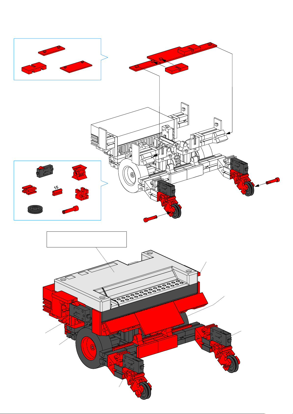
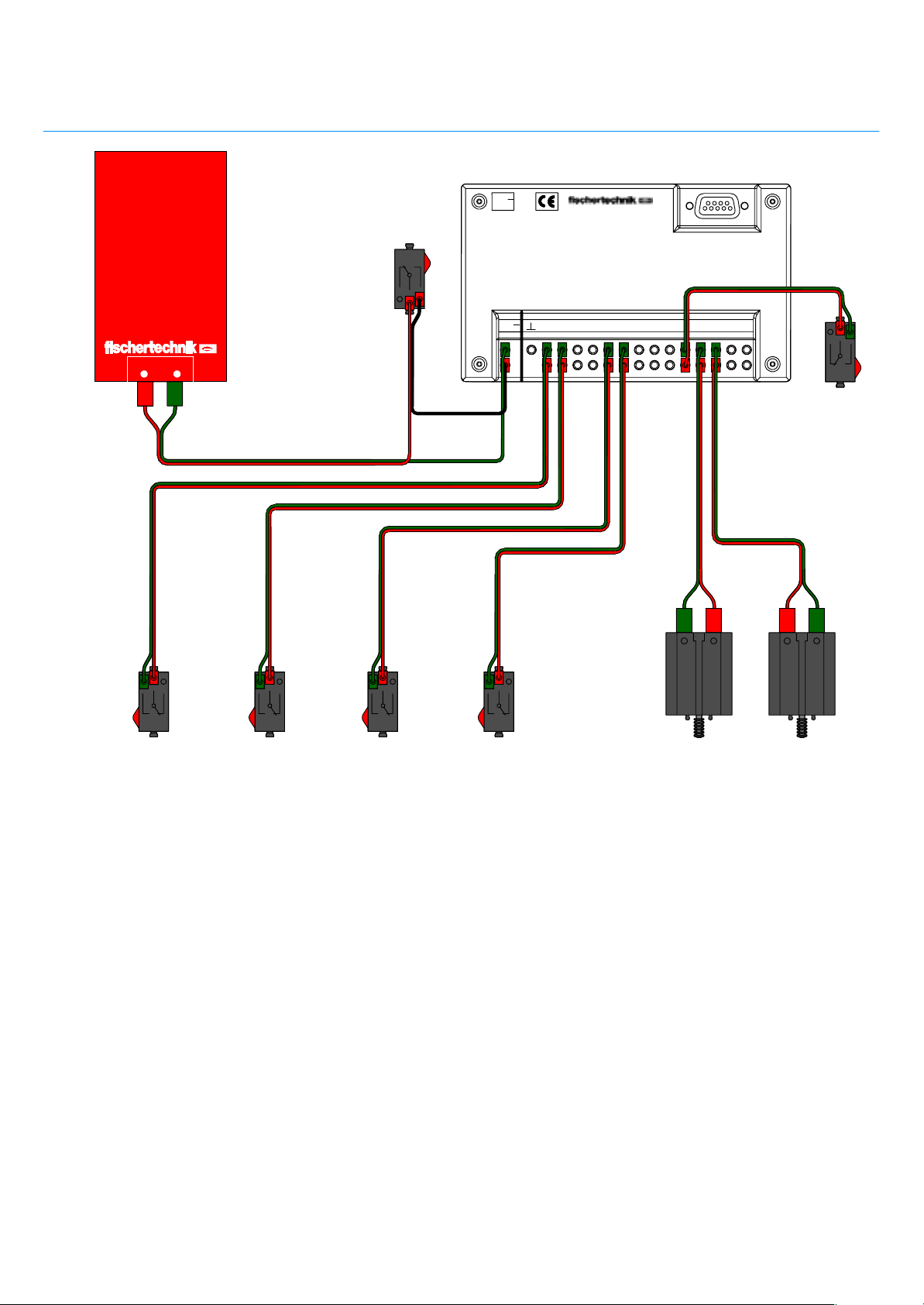
MR3 besitzt Rollen, die nach unten abklappen, wenn er
sich einem Abgrund, z.B. einer Tischkante, nähert.
Dadurch werden die Taster E3 und E4 ausgelöst. Je
nachdem, welcher Taster sich öffnet, kann das Modell
nach links oder rechts ausweichen oder umkehren.
M1
M2
Program example: mr3.mdl
Operational description:
MR3 is equipped with rollers that fold downwards
if the unit encounters open space under it, e.g., the
edge of a table.The rollers activate switches E3 and
E4. Depending on which switch is activated, the model
can turn to the left or the right, or reverse direction.
26
Page 29
MR4
folgt einer Lichtquelle
follows a light source
1–10
Seite
Page
16 – 18
16 – 18
11
60°
4x
2x
1x
2x
12
1x
1x
1x
1x
1x
27
Page 30
13
2x
2x
14
1x
1x
2x
2x
13
2x
2x
28
Power on/off
Montage Interface Seite 5
Mounting interface Page 5
M1/E1
E8, Reset
M2/E2
E4
E3
Page 31
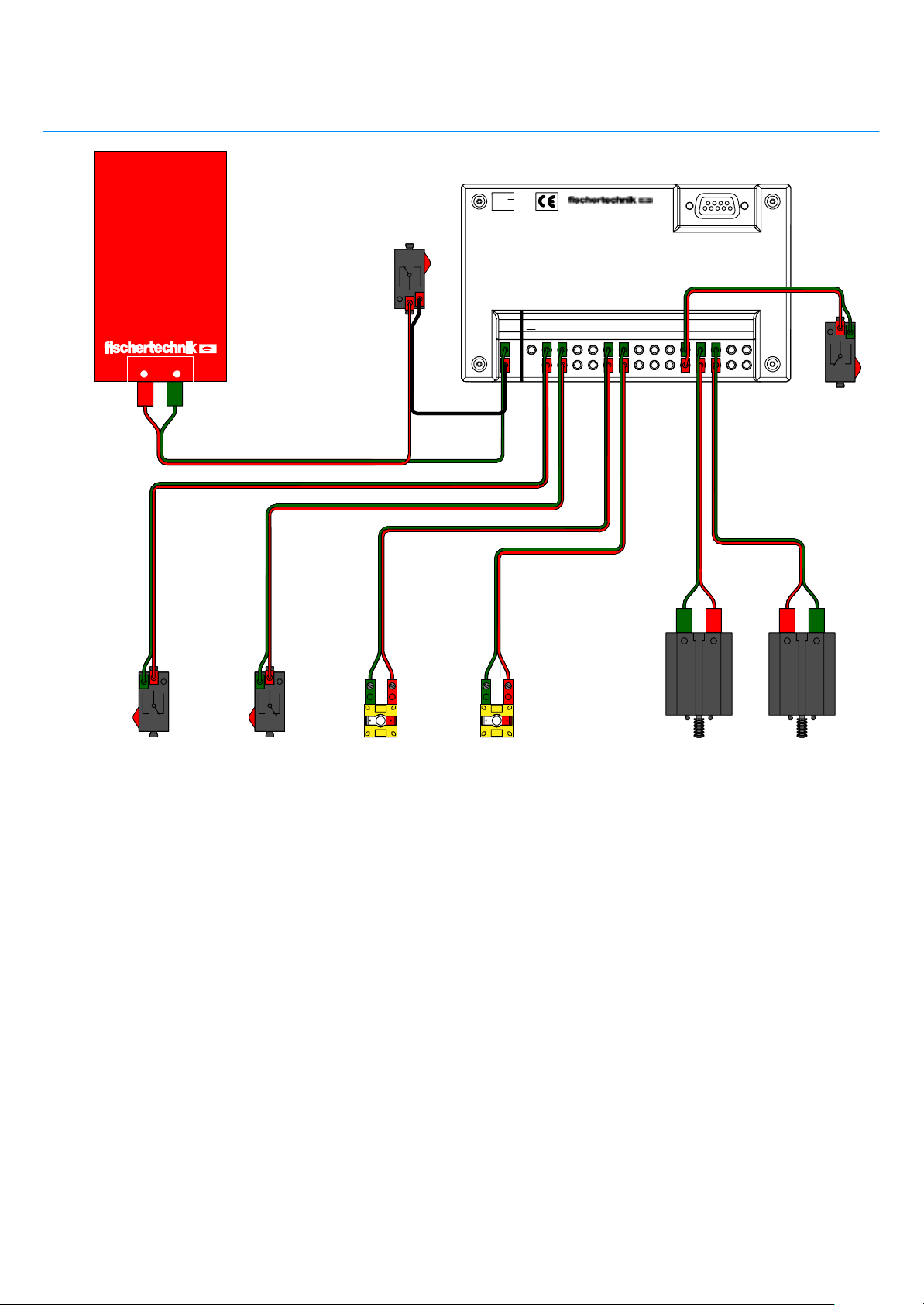
Schaltplan
Circuit diagram
Serielle Schnittstelle
Serial port
9V...
Power
on / off
Power–Block
+–
22 cm
22 cm 22 cm
22 cm
8 cm
22 cm
22 cm
E1 E2 EX EYE3 E4 E5 E6 E7 M1M2M3M4
9V..
.
E8
30 cm
30 cm
22 cm
22 cm
E8
Reset
E1 E2 M1
E3
Beispielprogramm: mr4.mdl
Funktionsweise:
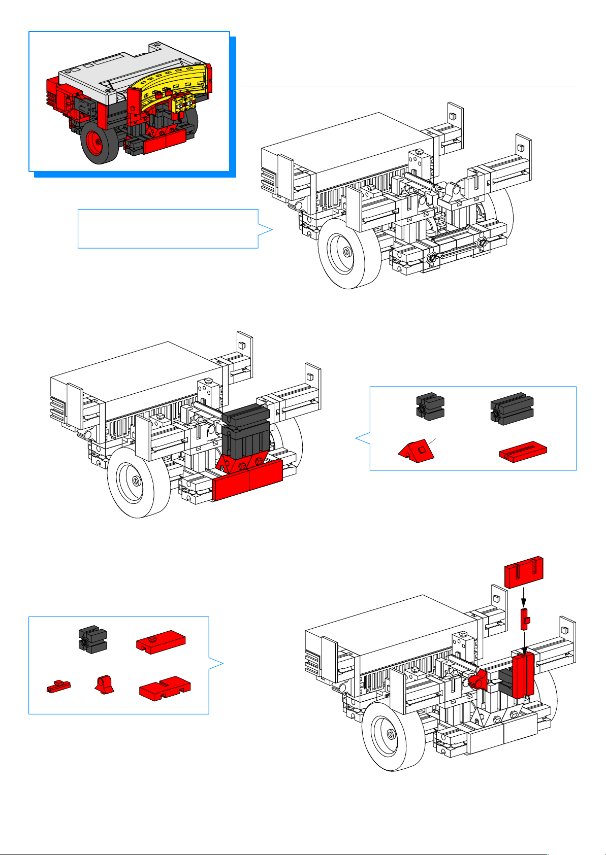
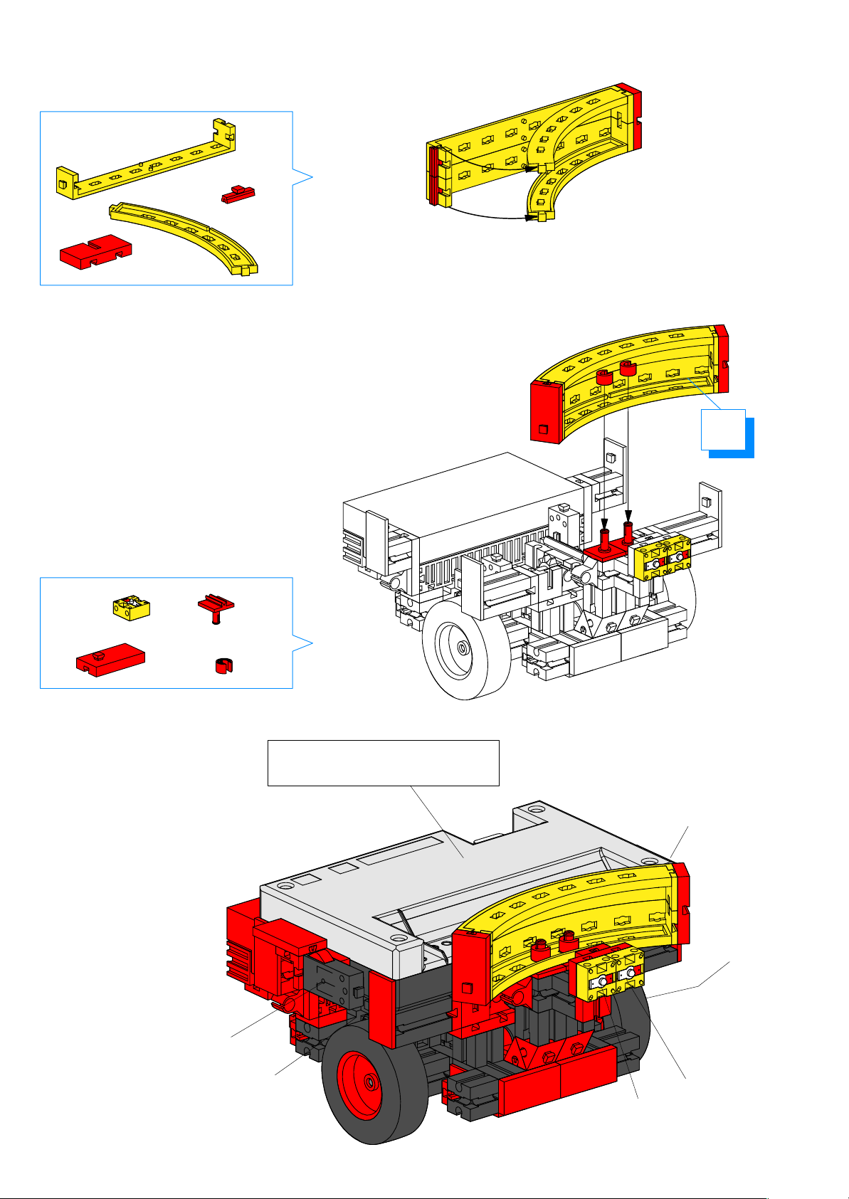
MR4 sucht sich zunächst eine Lichtquelle, die ihn
anstrahlt, z.B. eine Taschenlampe. Erkennen die beiden
Fototransistoren eine Lichtquelle, fährt MR4 darauf zu
und folgt dem Licht. Die Lichtquelle darf sich jedoch
nicht zu schnell oder zu ruckartig bewegen. Verliert das
Modell den Kontakt zum Lichtstrahl, beginnt es erneut
zu suchen.
E4
+
M1
M2
M2
+
Program example: mr4.mdl
Operational description:
MR4 first searches for a light source (e.g., a flashlight)
shining on it. If both phototransistors identify a light
source, MR4 moves towards it and follows it. However,
the light source must not be moved too rapidly, and
must move smoothly. If the model looses contact to
the light source, it begins a new search.
29
Page 32
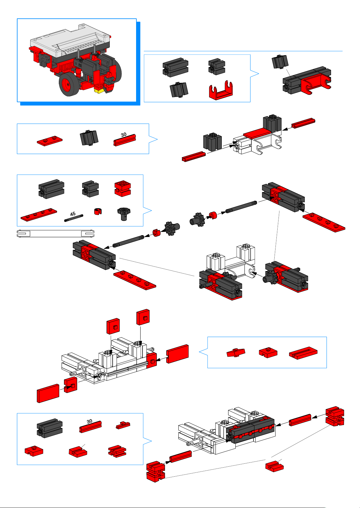
MR5
folgt einer Spur
follows a path
2
3
45
2x
1x
2x
2x
2x
2x
2x
2x
2x
2x
1
1x
1x
1x
1x
30
5
2x
2x
7,5°
2x
2x
2x
6x
4
2x
2x
2x
7,5°
Page 33
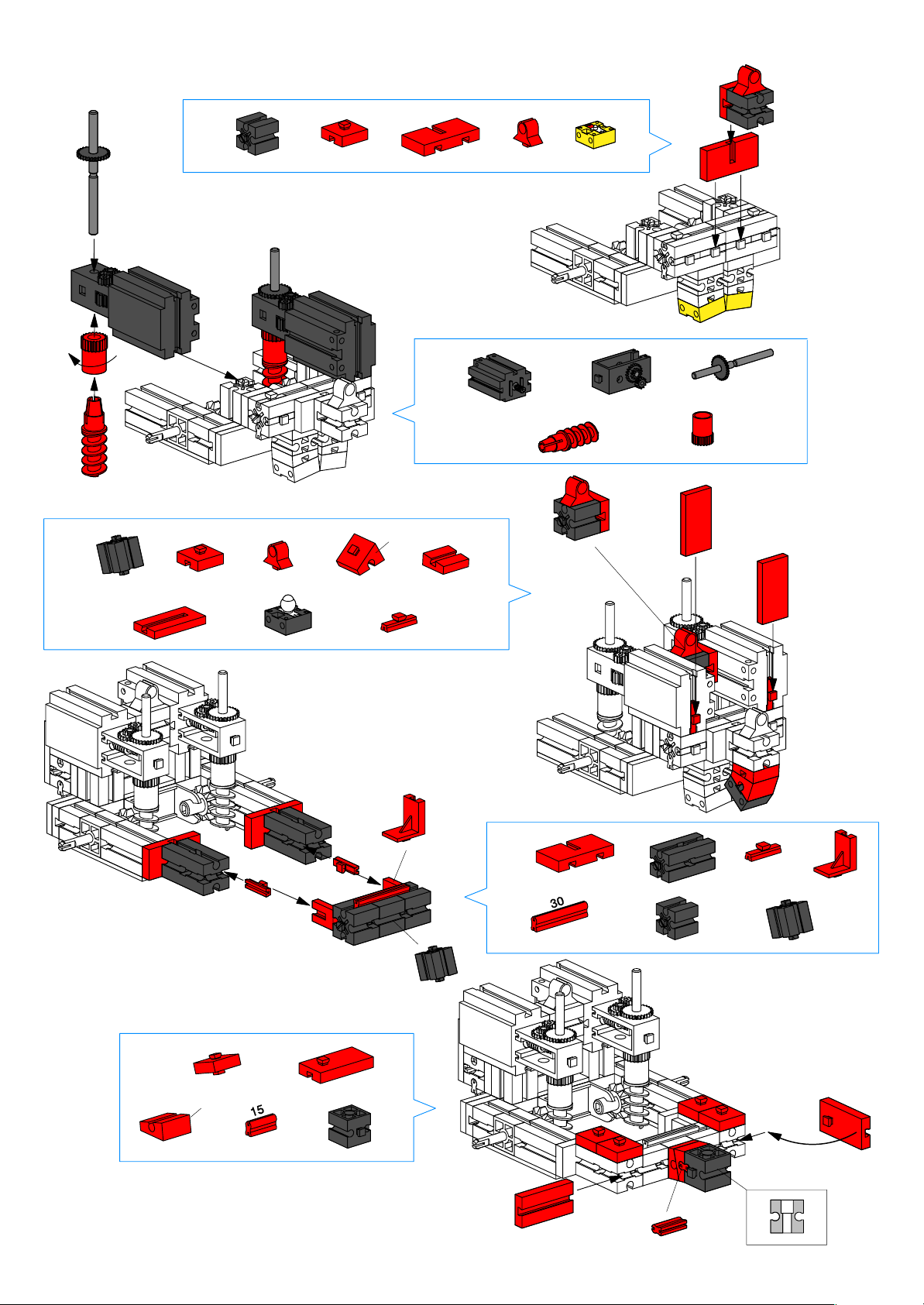
6
1x
1x 1x
1x
2x
8
1x
2x
1x
1x
30°
1x
2x1x
7
7,5°
1x
2x
2x
2x
2x
2x
10
2x
15°
4x
1x
1x
2x
9
2x 2x
2x
1x
2x
2x
1x
31
Page 34
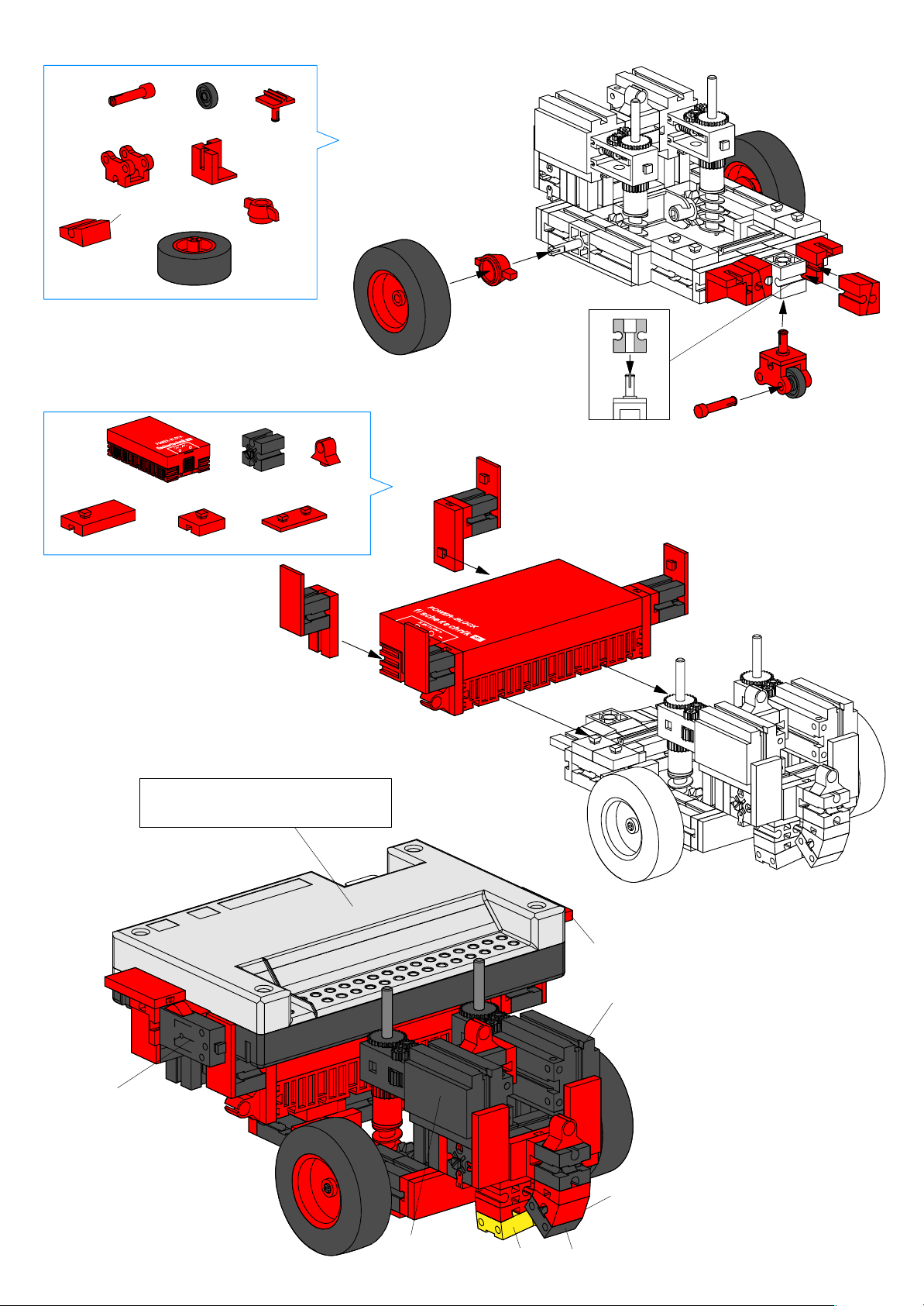
11
1x
1x
1x
12
4x
15°
4x
1x
1x
2x
2x
2x
2x
4x
1x
4x
Power on/off
Montage Interface Seite 5
Mounting interface Page 5
E8, Reset
M2
E2
32
M1
E1
M3
Page 35
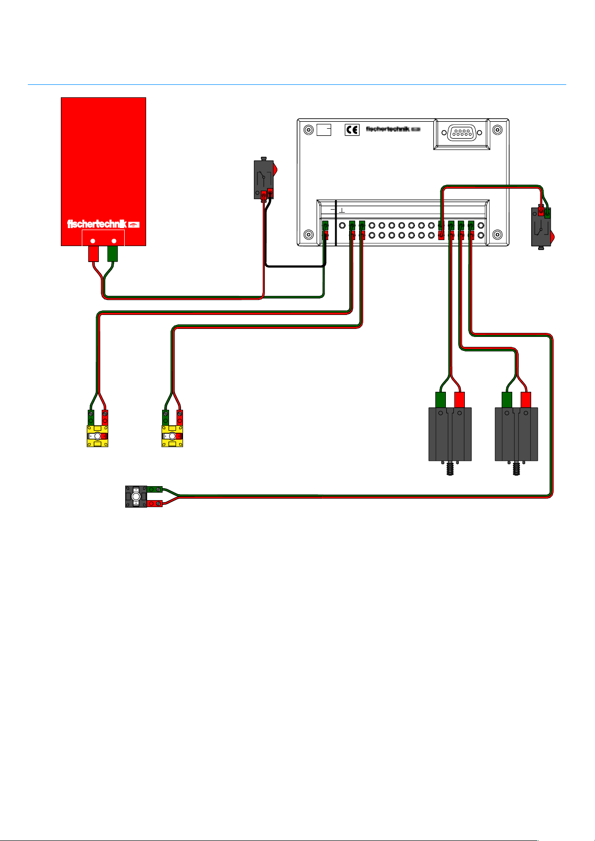
Schaltplan
Circuit diagram
Power
on / off
9V...
Serielle Schnittstelle
Serial port
22 cm
22 cm
Power–Block
+–
22 cm
+
E1
22 cm
22 cm
22 cm
E2
E1 E2 EX EYE3 E4 E5 E6 E7 M1M2M3M4
9V..
.
8 cm
+
30 cm
E8
22 cm
M1
E8
Reset
22 cm
M2
M3
Beispielprogramm: mr5.mdl
Funktionsweise:
MR5 ist in der Lage, auf einer schwarzen Spur, die
sich auf einem hellen Untergrund befindet, entlang zu
fahren. Die Spur sollte ca. 1 cm breit sein. Dazu klebt
man idealerweise schwarzes Isolierband auf einen
weißen Untergrund. Es funktioniert auch mit dickem
schwarzen Filzstift auf weißem Papier.
Bei diesem Modell muß man unter Umständen etwas
experimentieren, bis es einwandfrei funktioniert. Die
Lampe, die die Spur beleuchtet, scheint unterschiedlich
hell, je nachdem ob man mit Batterien, Akkus oder
einem Netzgerät arbeitet.
Je nach Umgebungshelligkeit und Kontrast zwischen
Spur und Untergrund ist die Schaltschwelle der Foto–
transistoren unterschiedlich. In der Interfacediagnose
kann man ablesen, ob die Fototransistoren die Spur als
dunkel und die Umgebung der Spur als hell erkennen.
Gegebenenfalls muß der Kontrast zwischen Spur und
Untergrund vergrößert oder die Position der Lampe
optimiert werden.
Program example: mr5.mdl
Operational description:
MR5 can proceed along a black path laid out against
a light background. The path should be approx. 1 cm
(1/2”) wide. The best way to make a path is to use
black insulation tape on a white surface. You can also
use a wide, black magic marker to draw a path on a
white sheet of paper.
You may need to experiment a bit to get the model to
work properly. The strength of light the model uses to
illuminate the path differs, depending on whether you
use batteries or the power adapter.
The activation threshold of the phototransistors also
varies, depending on the amount of ambient light and
the contrast between the path and the background.
The interface diagnostics indicate whether the photo–
transistors recognize the path as a dark strip and the
background as a light area.You may need to increase
the contrast between the path and the background, or
mover the light to a better position.
33
Page 36
 Loading...