

Page 1
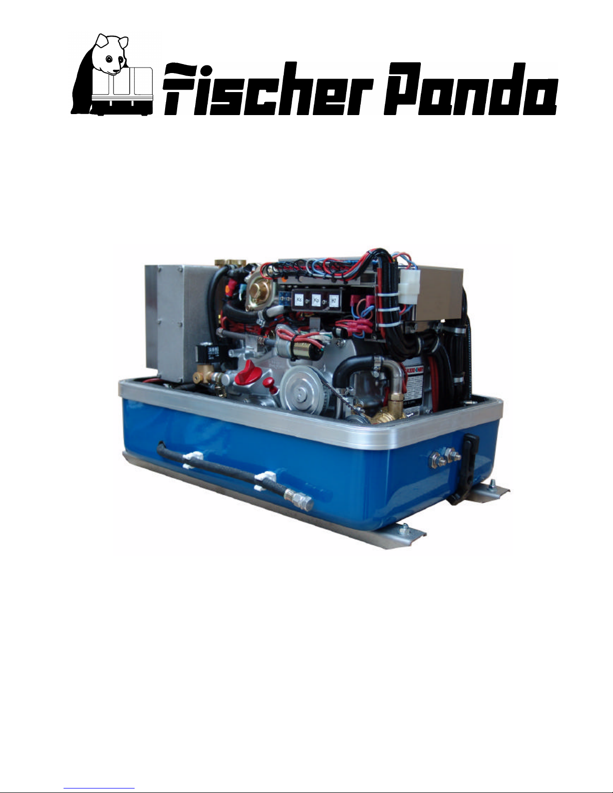
Marine Generator
Panda AGT-DC 4000 PMS
Super silent technology
24V - 140A / 4kW
Icemaster Fischer Panda
Operation manual
Description of the generator and operation manual
Page 2

ii
Fischer Panda
FISCHER GENERATORS have been manufactured since 1978 and are a well-known brand for first class diesel generators with especially effective sound-insulation.
Fischer has been one of the leading manufacturers in respect of quality and know-how during this period.
FISCHER, as the worldwide manufacturer of modern marine diesel generators, developed the Sailor-Silent series for
example and produced a GFK sound-insulated capsule as early as 1979 and the basis for new generator technology.
The companies Fischer and Icemaster amalgamated under the direction of Icemaster in 1988, in order to concentrate
on the development of new products. Production was moved to Paderborn.
The amalgamation of the two qualified companies led to the development of a complete new programme within a short
space of time. The aggregates developed at that time set new technological standards worldwide.
The aggregates became more efficient and powerful than other aggregates in the same nominal performance range,
because of the improved cooling. Panda generator demonstrated its superiority in several tests by renowned institutes
and magazines during the past years. The patented VCS (voltage Control System) means it can meet all demands
including motor speed. The start-booster (ASB) means Panda generators meet the highest demands in respect of
voltage stability and starting values A Panda generator, with the same drive motor, produces 15% more effective output
than the majority of conventional generators. This superiority in efficiency also ensures a fuel saving to the same extent.
The 100% water-cooled Panda Aggregate are currently manufactured in the performance range from 2 to 100 kW in
various versions. Fast running motors are preferred for performances up to approx 30 kW (Nominal speed 3000 rpm).
The heavier slow runners are preferred for the higher range. The fast running aggregates have proved themselves
many times for many uses, that they meet the demands in quality of yachts and vehicles, and offer space and weight
saving of 50% compared to slow running generators.
In addition to the Panda series, Icemaster also supply the super compact high-tech sound-insulated battery charging
aggregate from the DC/AC Panda AGT series, which is a very interesting solution for the production of mobile power.
The new HTG-alternators ensure that a charging rate of 285 amps is achieved that was scarcely thought possible for
this compact construction. This alternator replaces a separate shipboard generators (constant 230 volts AC with up to
3500 kW from the main machine)
ICEMASTER GmbH, 33104 Paderborn, reserves all rights regarding text and graphics. Details are given to the best of our knowledge. No liability is accepted for correctness. Technical modifications for improving the product without previous notice may be undertaken without notice. Before installation, it must be ensured that the Pictures,
diagrams and related material are applicable to the aggregate supplied. Enquiries must be made in case o doubt.
since 1977
Icemaster GmbH
since 1978
Fischer Marine
Generators
since 1988
Conclusion Fischer -
Icemaster GmbH
since 1988
100 % water cooled
Panda generators
since 1988
Panda Vehicle
Generators
25
20 10
10 10
Page 3
iii
CALIFORNIA
Proposition 65 Warning
Diesel engine exhaust and some of its constituents
are known to the State of California to cause cancer,
birth defects, and other reproductive harm.
Attention, Important Directions regarding Operation!
1. The installation certificate must be completed when taken into use, and certified by a signature.
2. The installation certificate must be despatched within two weeks of use to ICEMASTER.
3. The official guaranty confirmation will be completed by ICEMASTER after receipt and sent to the customer.
4. A guaranty must be shown to make any claims.
Claims against the guaranty will not be accepted of the above said instructions are not, or only partially, carried out.
Manufacturer declaration in terms of the machine guideline 98/37/EG .
The generator is in such a way developed that all assembly groups correspond to the CE guidelines. If machine guideline 98/37/EG is applicable, then it is forbidden to bring the generator into operation until it has been determined
that the system into which the generator is to be installed in also corresponds to the regulations of the machine guideline 98/37/EG. This concerns among other things the exhaust system, cooling system and the electrical installation.
The evaluation of the "protection against contact" can only be accomplished in connection with the respective
system. Likewise among other things responsibility for correct electrical connections, a safe ground wire connection,
foreign body and humidity protection, protection against humidity due to excessive condensation as well as the overheating through appropriate and inappropriate use in its installed state on the respective machine lies within the
responsibility of those who undertake installation of the generator in the system.
Use the advantages of the customer registration:
• Thus you receive to extended product informations, which are sometimes safety-relevant
• you receive, if necessarily free Upgrades
Far advantages:
By your full information Fischer Panda technicians can give you fast assistance, since 90% of the disturbances result
from errors in the periphery.
Problems due to errors in the installation can be recognized in the apron.
Technical Support per Internet: [email protected]
Page 4
iv
Safety Instructions
The electrical Installations may only be carried out be trained and
tested personnel!
The generator may not be taken into use with the cover removed.
The rotating parts (belt-pulley, belts, etc) must be so covered and protected do that there is no danger to life and
body!
If a sound insulation covering must be produced at the place of installation, then well-placed signs must show that
the generator can only be switched on with a closed capsule.
All servicing-, maintenance or repair work may only carried out, when the motor is not running.
Electrical voltages above 48 volts ( battery chargers greater than 36 volts) are always dangerous to life). The rules of
the respective regional authority must be adhered to. Only an electrician may carry out installation of the electrical
connections for safety reasons.
General safety references for the enterprise of a AGT generator.
With all energized systems, with which the current is more than 50 Ampère, special safety precautions must be
made, in order to protect the environment of the components against fire.
It is to be ensured absolutely that at the battery a main switch in well accessible place is accommodated, so that with
danger of the main switches can be separated immediately. The main switch must be however also directly at the
battery installed. If this place is not well accessible, a power relay must be used instead of the main switch which can
be served manually, which can be served then if necessary from different places. The switches for the power relay
are to mark accordingly as main switches DC battery "with danger switch off!".
Cooling of the diode block.
The diode block is cooled with fresh water. A normal cooling of the diode block is therefore only possible, as long as
the cooling water supply of the generator functions duly. The cooling water supply of the generator must be so furnished therefore that by a wide dirt deflector it is guaranteed that from outside no dirt can be sucked in into the line
system. If this is not attainable, the supply must be secured by a flow switch or a negative pressure switch. The
generator must be switched off, if the cooling water supply is impair.
The temperature safety device on the diode block can be regarded only as additional safety device. The temperature
rise at the diodes is so fast that the diodes can be damaged during a unique interruption of the cooling water supply.
A safe protection from damage of the diodes is not possible by the temperature monitoring on the diode radiator box.
Thus this can take place only by means of an appropriate external monitoring of the cooling system.
ATTENTION!
Do not connect the minus pole of the starter battery to the ground of the boat because of galvanic reason.
Warning!
Never start the generator with the battery disconnected, the diodes will be damaged!
CAUTION!
Contact of the electrical contacts may be DANGER TO LIVE!
Page 5
v
CAUTION!
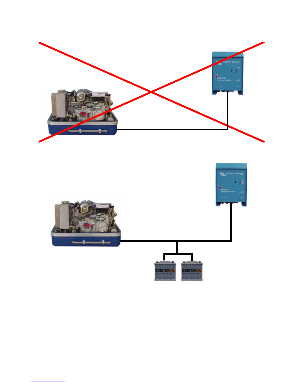
The AGT-generator is not allowed to be connected to an inverter (without batteries)!
The Inverter generates voltage peaks, which can destroy the rectifier diodes of the generator!
A battery must always be connected to the inverter as a capacity!
Recommended capacity at 12V ≥ 240Ah at 24V ≥ 120Ah
The screws at the electric rectifier may be pulled tight only with a torque wrench. Torque 4Nm.
The battery cable must be secured at the generator and at the batteries with appropriate safety devices.
The generator is also include into the CO2 - fire-extinguishing system.
Page 6

vi
Measures to the fire protection.
All construction units in the environment of energized parts, which carry more than 50 Amp., must be fire protectionmoderately secured.
All junction points at the energized parts must be examined regularly on heating up (infrared thermometers).
Safety Instrictions for the Handling with Batteries
These instructions must be noticed additionally to the instructions of the battery manufacturer:
• If the batteries are working, someone should be in your near area to help you in a case of emergency.
• Water and soap must be hold ready if battery acid corrode your skin.
• Wear eye protection and protective clothing. During working with the batteries don´t touch the eyes.
• If you got a acid splash on your skin or clothing grow it with much water and soap out.
• If you got acid in your eyes rinse them immediately with clear water until no cauterization is noticeable. Visit immediate a doctor.
• Don´t smoke in the near of the batteries. Avoid naked flames or open fires. In the area of batteries exists danger
of explosions.
• Pay attention that no tools fall on the battery poles, if necessary cover them.
• During the installation don´t wear a wrist watch or arm jewels, you can create under these circumstances a battery
short-circuit. Burning of the skin could be the result.
• Protect every battery contact against unintentional touch.
• Use only cyclical profoundly dischargeable batteries. Starter batteries are not appropriate. Lead-gel batteries are
commended. They are maintenance-free, profoundly dischargeable and not produce gas.
• Do not charge a frozen battery.
• Avoid a batterie short-curcuit.
• Take care of a good ventilation of the battery to drain off developing gas.
• The battery connection terminals must be checked of a tight contact at least before operating.
• The battery connection cable must be carefully mounted and checked about incorrect heating at operation with
load. The vibrating devices must be regulary checked about scour points and flaw in the isolation.
Page 7

Panda PMS AGT-DC 4000 - 24V - Table of contents - Page 1
Table of contents
A The Panda Generator .........................................................................................................3
A.1 Description of the Generator ................................................................................................ 3
A.1.1 Right Side View ......................................................................................................................... 3
A.1.2 Left Side View ........................................................................................................................... 4
A.1.3 Front View................................................................................................................................. 5
A.1.4 Back View.................................................................................................................................. 6
A.1.5 View from Above....................................................................................................................... 7
A.2 Details of functionl units ......................................................................................................8
A.2.1 Remote control panel................................................................................................................ 8
A.2.2 Components of Cooling System (raw water)............................................................................. 9
A.2.3 Components of Cooling Systems (Freshwater)....................................................................... 11
A.2.4 Components of the Fuel System............................................................................................. 14
A.2.5 Components of Combustion Air ............................................................................................. 16
A.2.6 Components of the Electrical System ..................................................................................... 17
A.2.7 Sensors and switches for operating surveillance.................................................................... 21
A.2.8 Components of the Oil Circuit ................................................................................................. 23
A.2.9 External Components.............................................................................................................. 24
A.3 Operation Instructions ........................................................................................................ 25
A.3.1 Daily routine checks before starting........................................................................................ 25
A.3.2 Starting Generator................................................................................................................... 26
A.3.3 Stopping the Generator........................................................................................................... 26
Page 8

Page 2 Panda PMS AGT-DC 4000 - 24V - Table of contents
Page 9
The Panda Generator
Panda PMS AGT-DC 4000 - 24V - Chapter A: The Panda Generator Page 3
A. The Panda Generator
A.1 Description of the Generator
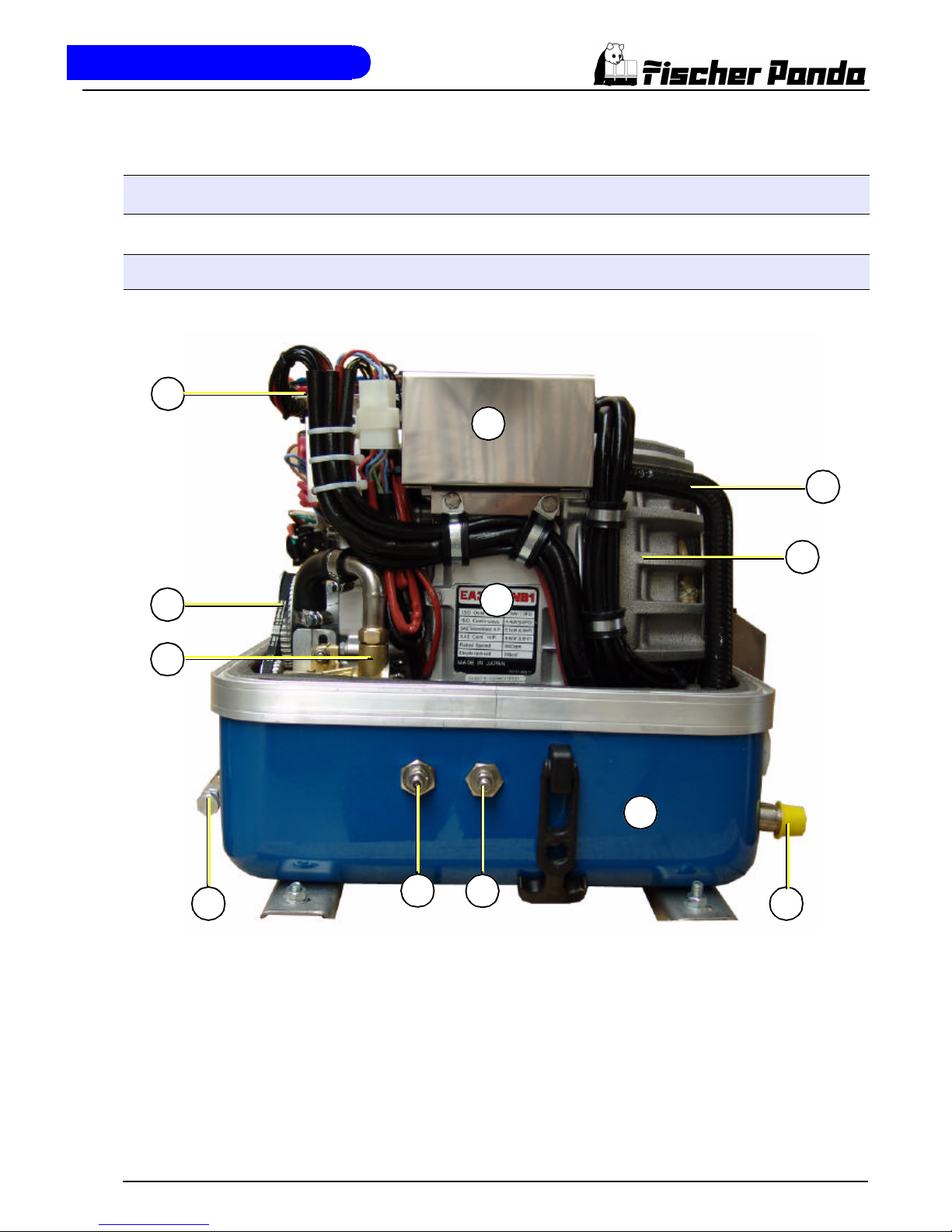
A.1.1 Right Side View
01
03
04
08
10
05
11
02
09
12
06
07
01) Terminal block for remote control panel, fuses and
relays
02) Cooling water tank
03) Toothed belt
04) Raw water pump
05) Oil drain hose
06) Connection starter battery minus (-)
07) Connection starter battery plus (+)
08) Sound cover base part
09) Raw water inlet
10) Engine Kubota EA300
11) Generator housing with coil
12) Coolant pipe
Page 10
The Panda Generator
Page 4 Panda PMS AGT-DC 4000 - 24V - Chapter A: The Panda Generator
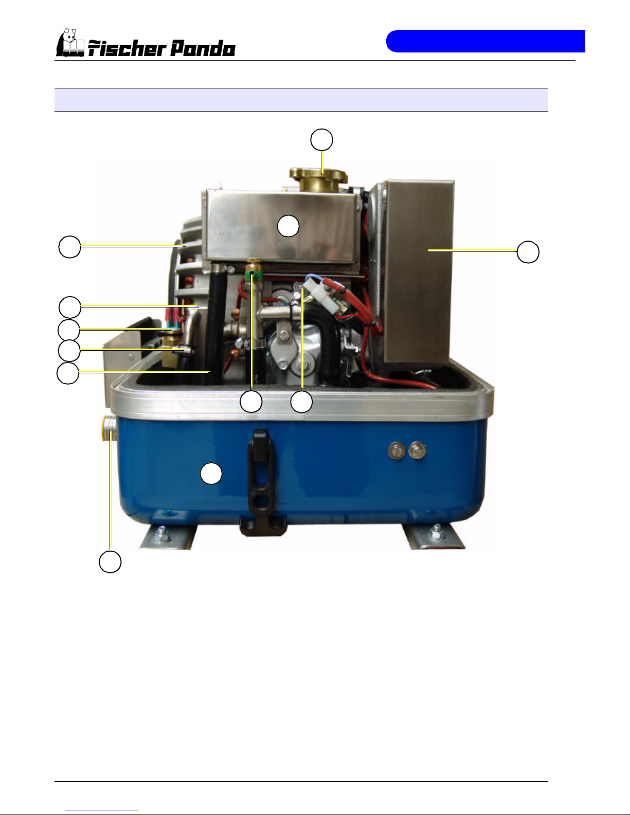
A.1.2 Left Side View
01
11
07
06
10
02
03
05
04
08 09
12
01) Generator housing with coil
02) Water-cooled exhaust elbow
03) Thermo-switch at exhaust elbow
04) Raw water injection pipe
05) Coolant pipe, water tank - heat exchanger
06) Exhaust outlet
07) Sound cover base part
08) Ventilation valve
09) Injection nozzle
10) Suction port at air suction housing
11) Cooling water tank
12) Cooling water filler neck
Page 11
The Panda Generator
Panda PMS AGT-DC 4000 - 24V - Chapter A: The Panda Generator Page 5
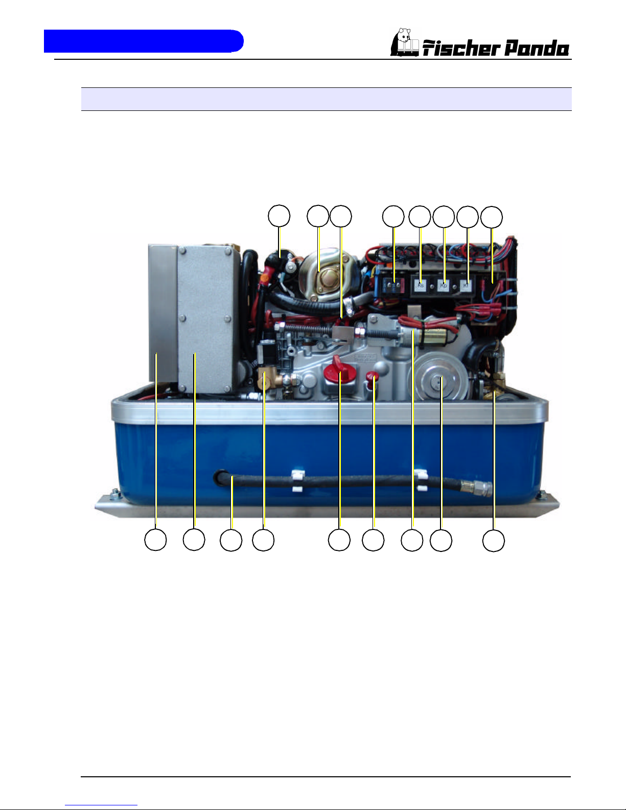
A.1.3 Front View
16
17
01
13
12
11
10
09
14
15
02
03
04
05
06
07 08
01) Solenoid switch for starter motor
02) Starter motor
03) Oil pressure switch
04) Electrical fuses (blue=15A, white=10A)
05) Start relay Ks
06) Glow-plug relay K2
07) Fuel pump relay K3
08) Release relay K4
09) Raw water pump
10) Pulley
11) Actuator
12) Oil dipstick
13) Engine oil filler neck
14) Fuel solenoid valve
15) Oil drain hose
16) Air suction housing with air filter inlet
17) Suction port
Page 12
The Panda Generator
Page 6 Panda PMS AGT-DC 4000 - 24V - Chapter A: The Panda Generator
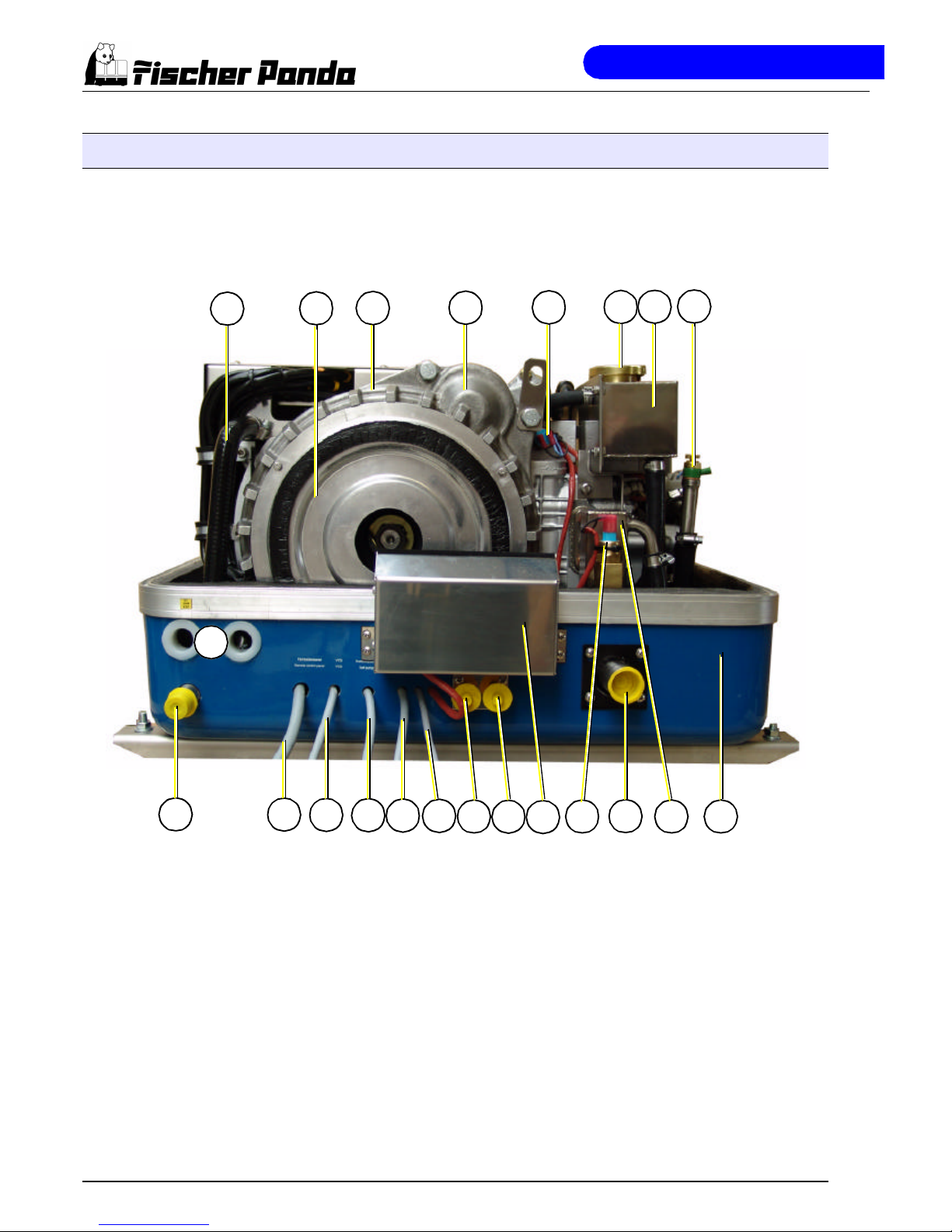
A.1.4 Back View
22
20
19
18
17 16
11
15
14
08
07
06
05
0403
02
01
12 10
21
09
13
01) Coolant pipe
02) Generator front cover
03) Generator housing with coil
04) Starter motor
05) Thermo-switch at engine
06) Coolant filler neck
07) Cooling water tank
08) Ventilation valve
09) Sound cover base part
10) Water-cooled exhaust elbow
11) Exhaust outlet
12) Thermo-switch at exhaust elbow
13) Cover for DC/DC-converter
14) Connection for fuel OUT
15) Connection for fuel IN
16) Cable for voltage sense
17) Cable for shunt
18) Cable for fuel pump
19) Cable for VCS
20) Cable for remote control panel
21) Passage for cable of battery bank
22) Raw water inlet
Page 13
The Panda Generator
Panda PMS AGT-DC 4000 - 24V - Chapter A: The Panda Generator Page 7
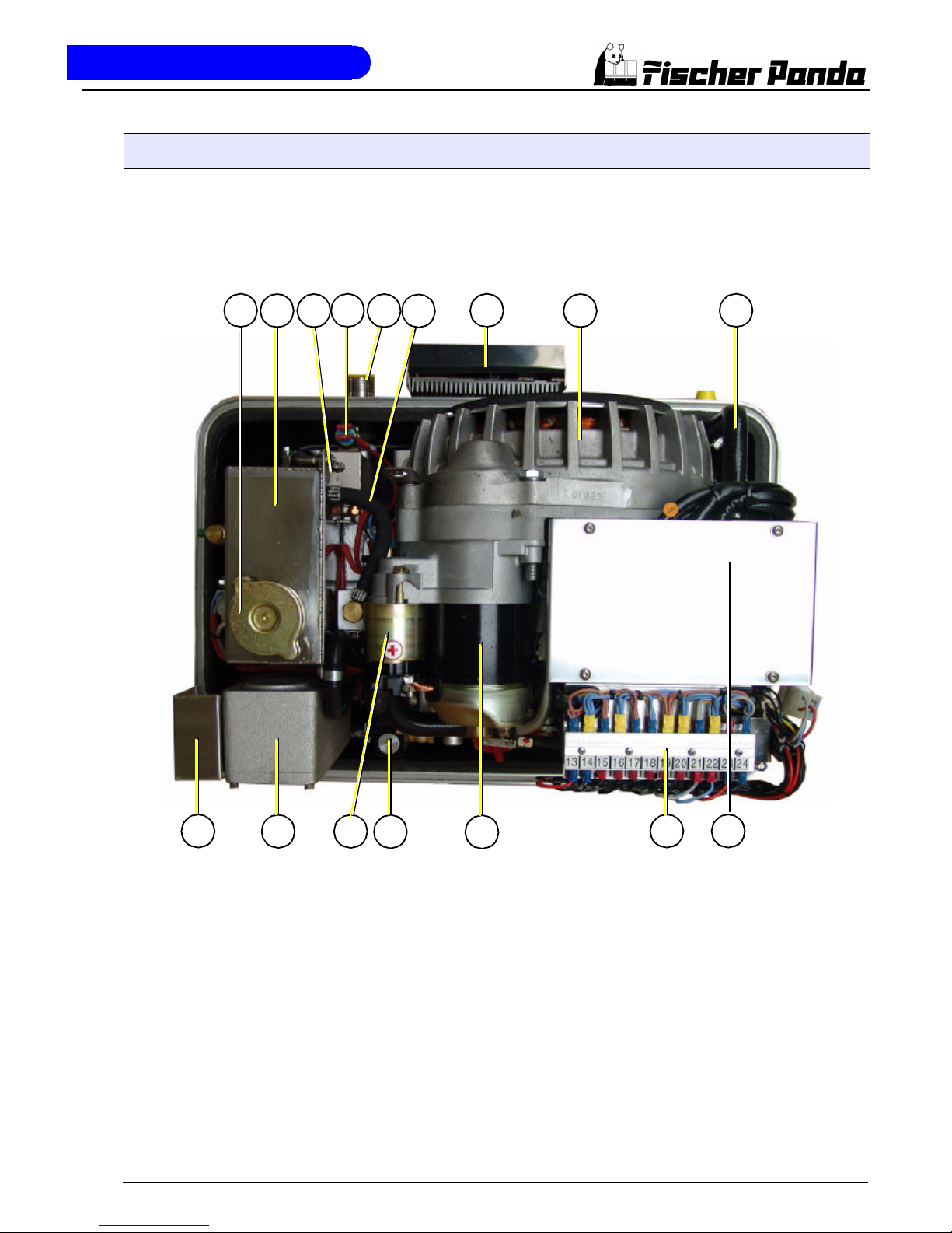
A.1.5 View from Above
01
16 11 10
04 07 09
02 05
15
13
12
14
03 08
06
01) Cooling water filler neck
02) Cooling water tank
03) Water-cooled exhaust elbow
04) Thermo-switch at exhaust elbow
05) Exhaust outlet
06) Ventilation hose
07) Cover for DC/DC-converter
08) Generator housing with coil
09) Coolant pipe
10) Diode plate under protection cover
11) Terminal block for remote control panel, fuses and
relays
12) Starter motor
13) Fuel solenoid valve
14) Solenoid switch for starter motor
15) Air suction housing with air filter inlet
16) Suction port
Page 14
The Panda Generator
Page 8 Panda PMS AGT-DC 4000 - 24V - Chapter A: The Panda Generator
A.2 Details of functionl units
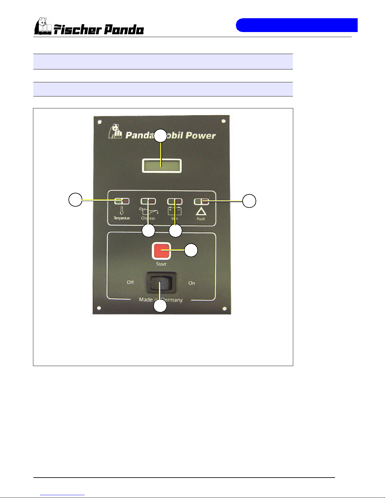
A.2.1 Remote control panel
Fig. A.1: Remote control panel
Automatic Start Option
An automatic start option is available as an accessory. This includes a separate control board,
which is connected to the main remote control board panel. The Automatic Start Option allows
the generator to be started by means of an external signal (i.e Battery Monitor). A speed gauge
and a sensor for speed pick-up are additionally necessary in addition to the automatic start
option. (See Component Automatic Start)
01
02
03
07
05
04
06
01) Betriebsstundenzähler
02) Leuchte für Motortemperatur
03) Leuchte für Öldruckleuchte
04) Leuchte für Batterieladespannung
05) Leuchte für Betriebszustand
06) Generator „Start“-Taste
07) Panel „Stand by“-Taste
Page 15
The Panda Generator
Panda PMS AGT-DC 4000 - 24V - Chapter A: The Panda Generator Page 9
A.2.2 Components of Cooling System (raw water)
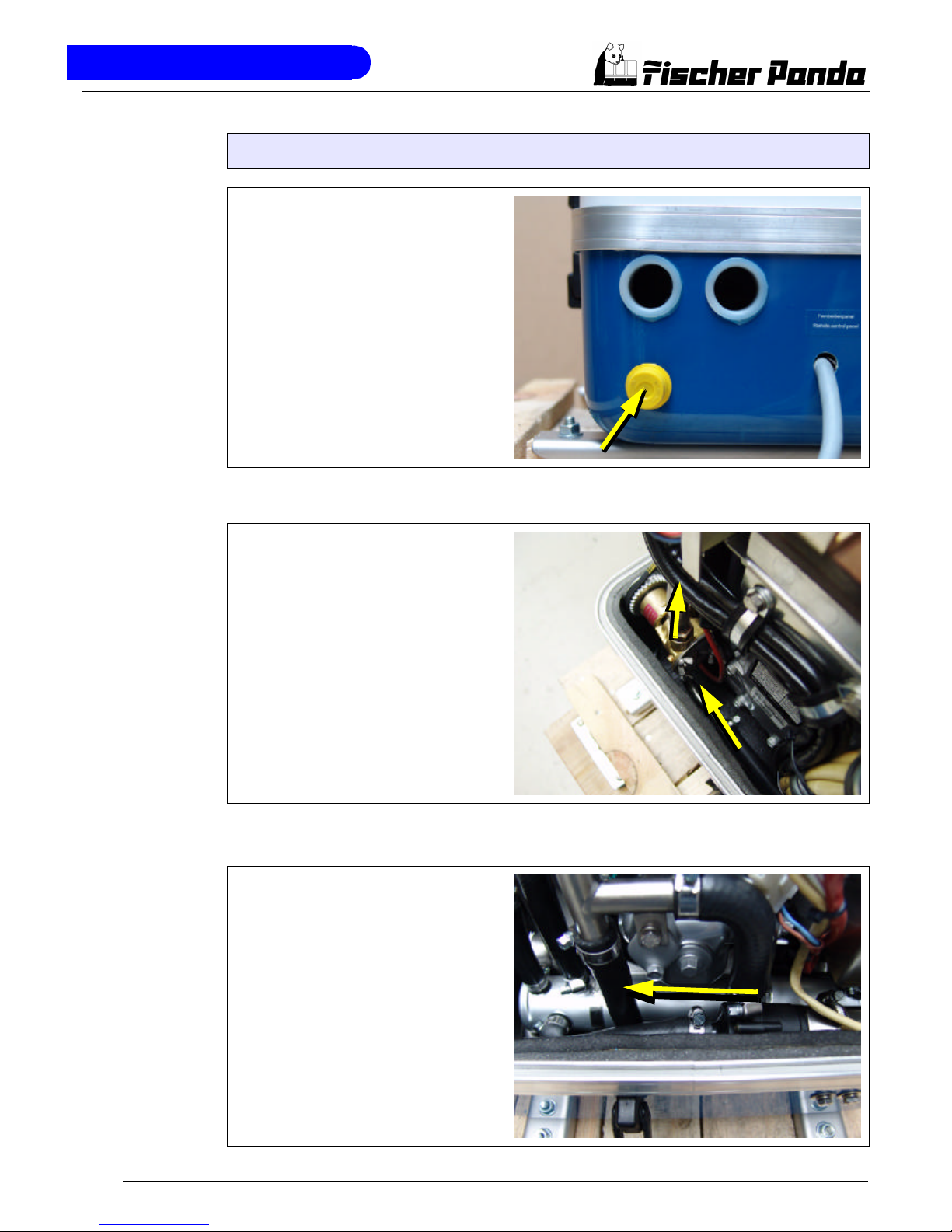
Raw water inlet
The diagram shows the supply pipes for
the generator. The connection neck for
the raw water connection is shown on the
left hand side. The cross-section of the
intake pipe should be nominally larger
than the generator connection.
Fig. A.2: Raw water inlet
Seawater impeller pump
The raw water pump is fitted with a rubber
impeller. This pump is self-inductive. If,
for example, you forget to open the sea
valve, then you must expect the impeller
to be destroyed after a short period of
time. It is recommended to store several
impellers on board as spare parts.
Fig. A.3: Raw water pump
Heat exchanger
Separates the seawater system from the
freshwater system.
Fig. A.4: Heat exchanger
Page 16
The Panda Generator
Page 10 Panda PMS AGT-DC 4000 - 24V - Chapter A: The Panda Generator
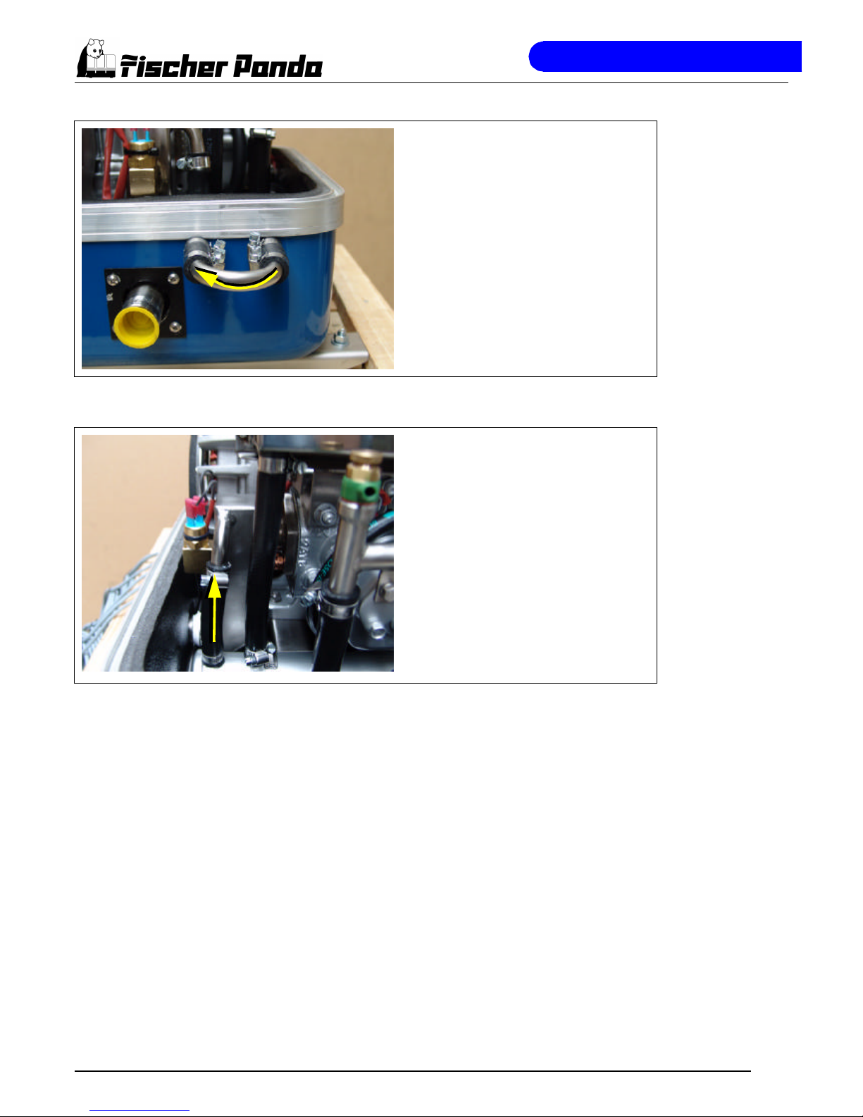
Ventilation valve
A siphon must be installed if the generator
sinks below the water line because of the
rocking of the boat, even if it is only for a
short period of time. A hosepipe on the
generator casing has been produced for
this. Both connecting pieces are bridged
by a formed piece of pipe.
Fig. A.5: Ventilation valve
Cooling water injector nozzle
The injection point for the marine generator water-cooled exhaust system is situated at the exhaust connection pieces The
exhaust connections must be regularly
checked for signs of corrosion.
Fig. A.6: Cooling water injector nozzle
Page 17
The Panda Generator
Panda PMS AGT-DC 4000 - 24V - Chapter A: The Panda Generator Page 11
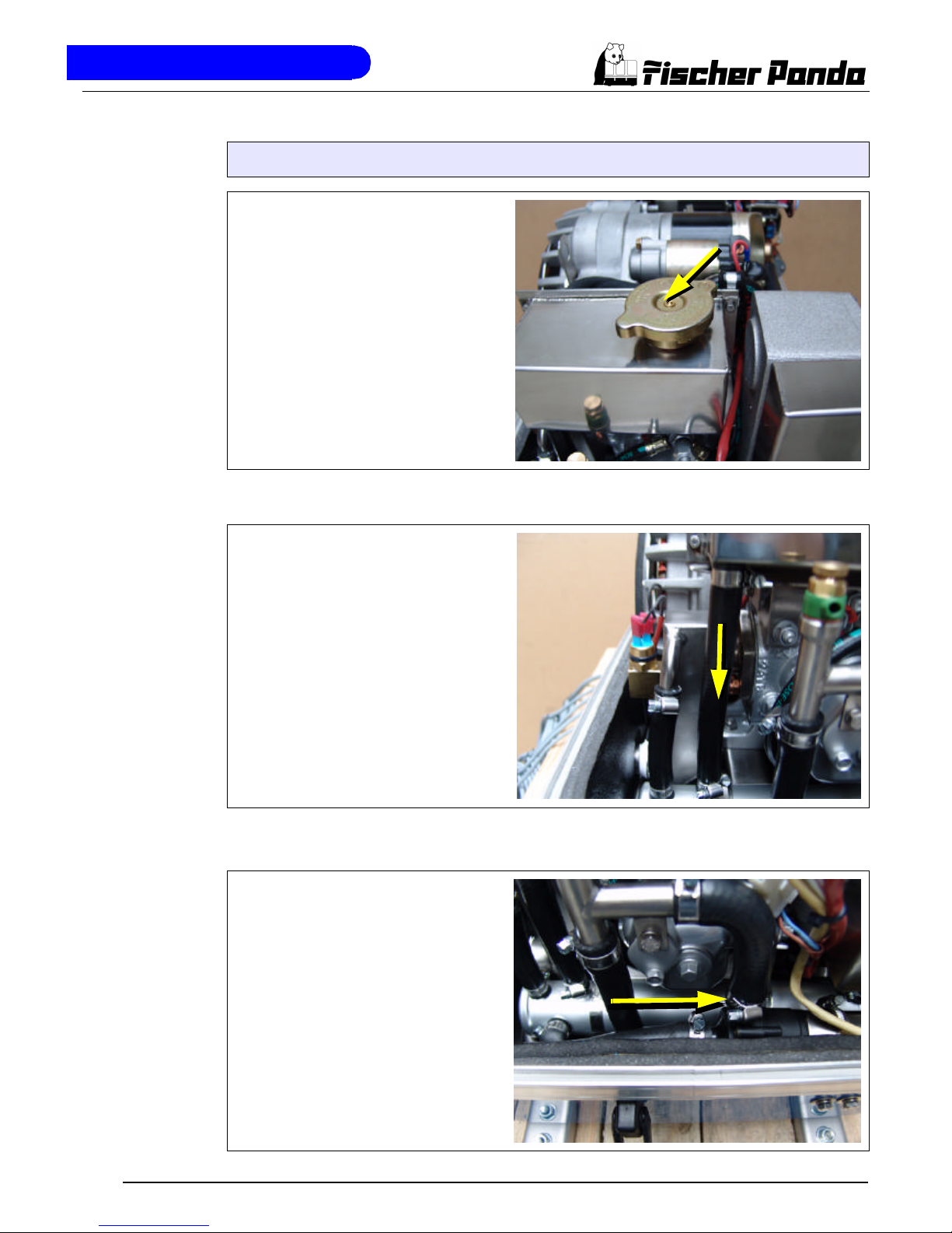
A.2.3 Components of Cooling Systems (Freshwater)
Cooling water filler neck
The cooling water filler neck is situated at
the colling water tank and only used,
when the generator is initially started.
Since the generator is normally already filled with cooling water, these components
are only by the user, if repairs are to be
carried out.
Fig. A.7: Cooling water filler neck
Freshwater backflow
The cooling water is fed to the heat
exchanger from the cooling water tank by
means of the pipe shown in the diagram.
Fig. A.8: Freshwater backflow
Heat exchanger
Separates the seawater system from the
freshwater system.
Fig. A.9: Heat exchanger
Page 18
The Panda Generator
Page 12 Panda PMS AGT-DC 4000 - 24V - Chapter A: The Panda Generator
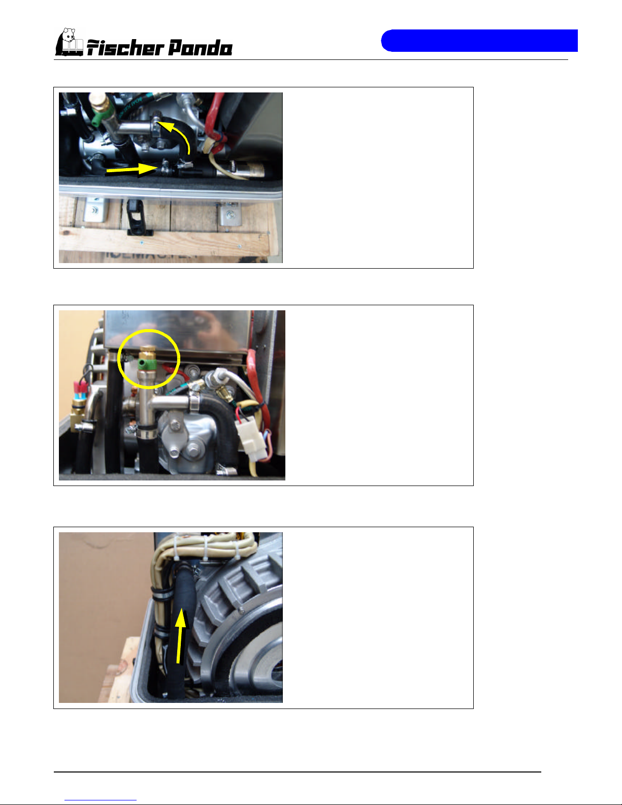
Internal cooling water pump
The diesel motor cooling water pump (see
arrow) aids the circulation of the internal
freshwater system.
Fig. A.10: Internal cooling water pump
Ventilation valve cooling water pump
The ventilation screw above the cooling
water pump casing may not be opened,
whilst the generator is running. If this
occurs by mistake, air will be drawn
through the opening. Extensive ventilation
of the whole system is then necessary.
Fig. A.11: Ventilation valve cooling water pump
Water-cooled diode plate
Coolant pipe intake into the diode plate.
Fig. A.12: Water-cooled diode plate
Page 19
The Panda Generator
Panda PMS AGT-DC 4000 - 24V - Chapter A: The Panda Generator Page 13
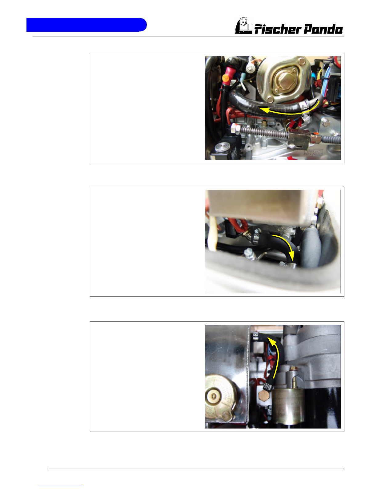
Coolant pipe, dioden plate - engine
Fig. A.13: Coolant pipe
Coolant outtake engine
The coolant gets below of the engine out
into the heat exchanger.
Fig. A.14: Cooant outtake engine
Ventilation pipe
Fig. A.15: Ventilation pipe
Page 20
The Panda Generator
Page 14 Panda PMS AGT-DC 4000 - 24V - Chapter A: The Panda Generator
A.2.4 Components of the Fuel System
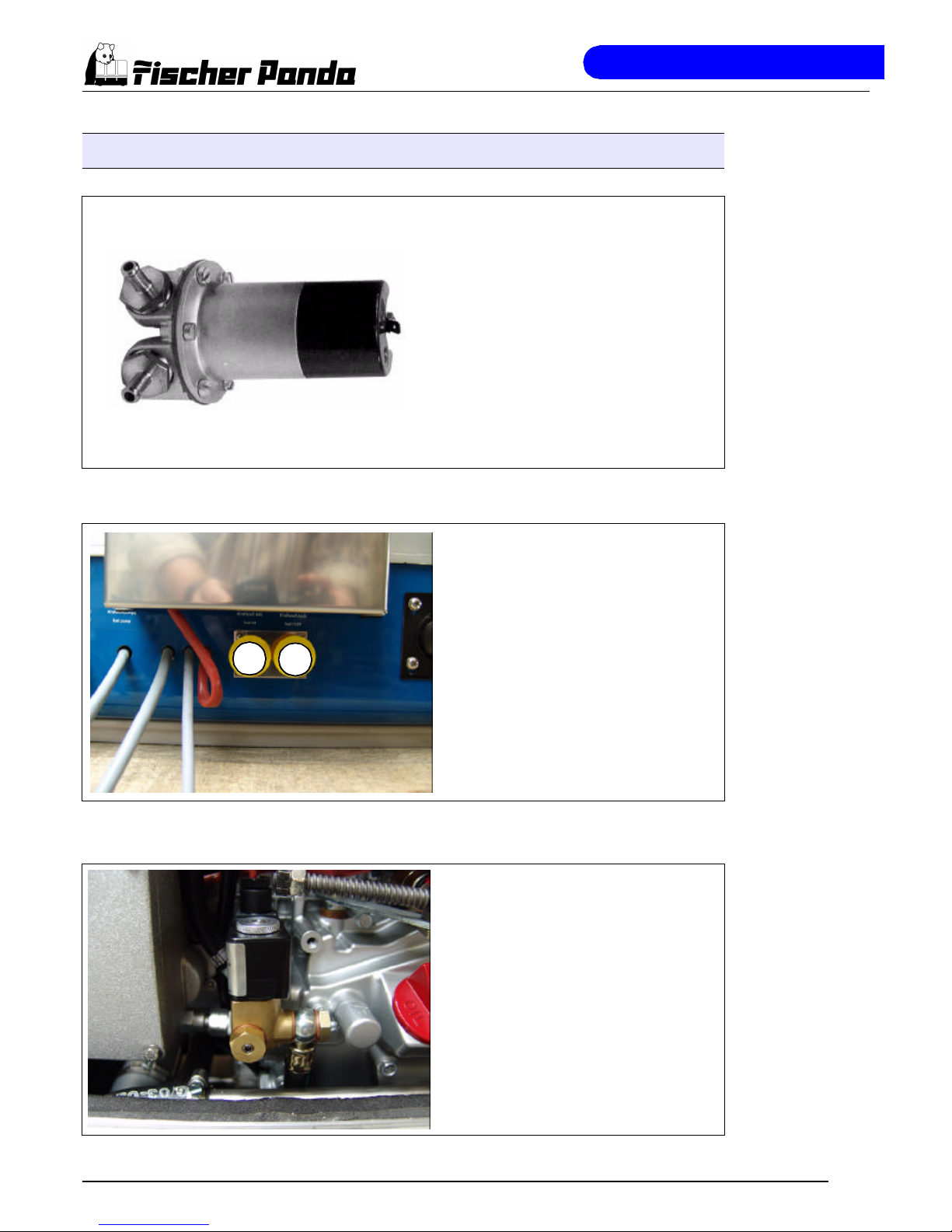
External fuel pump
The Panda generator is always supplied
with an external, electrical (12 V of DC) fuel
pump. The fuel pump must be always
installed in the proximity of the tank. The
electrical connections with the lead planned
for it are before-installed at the generator.
Since the suction height and the supply
pressure are limited, it can be sometimes
possible that for reinforcement a second
pump must be installed.
Fig. A.16: External fuel pump
Connecting pieces for the fuel pipe
1. Fuel intake
2. Fuel backflow
Fig. A.17: Fuel connections
Fuel solenoid valve
The fuel solenoid valve opens automatically if „START“ is pressed on the remote
control panel“. The solenoid closes, if the
generator is switched to „OFF“ position.
It takes a few seconds before the generator
stops. If the generator does not start or
does not run smoothly (i.e. stutters), or
does not attain full speed, then the cause is
fore-mostly the solenoid.
Fig. A.18: Fuel solenoid valve
1
2
Page 21
The Panda Generator
Panda PMS AGT-DC 4000 - 24V - Chapter A: The Panda Generator Page 15
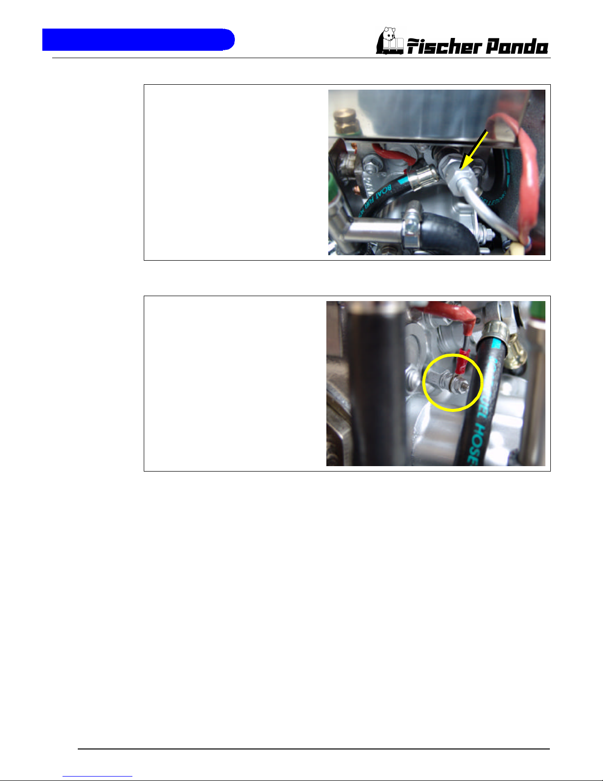
Injection nozzle
If the engine does not start after the ventilation, the fuel injection line must be deaerated.
Fig. A.19: Injection nozzle
Glow plug
The glow plug serve the pre-chamber for
the heating with cold start. The heat-treat
fixture must be operated, if the temperature of the generator is under 16°C. This
is practically with each start the case. The
heat-treat fixture may be held down also
during start and favoured the starting procedure.
Fig. A.20: Glow plug
Page 22
The Panda Generator
Page 16 Panda PMS AGT-DC 4000 - 24V - Chapter A: The Panda Generator
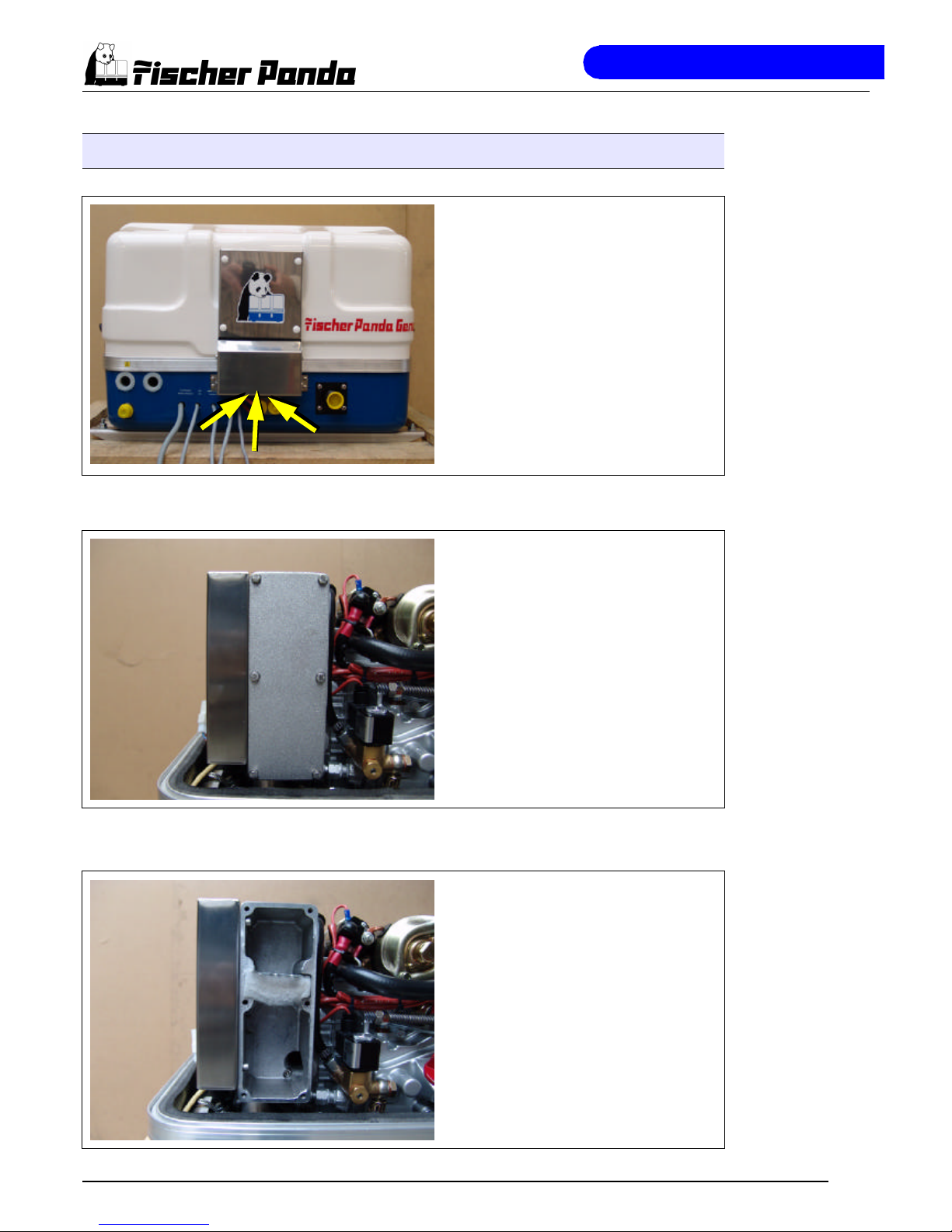
A.2.5 Components of Combustion Air
Air suction openings at the sound
cover
The sound cover is provided at the upper
surface with drillings, through which the
combustion air can influx.
It must be consistently paid attention that
the generator is installed in such a way
that from no water can arrive into the proximity of these air openings.
Fig. A.21: Combustion air intake
Air suction housing
Remove the cover to look indes the housing. There is a filter element. This must
be checked from timt to time.
Fig. A.22: Air suction housing
Air suction housing with air filter set
The figure shows the air filter element in
the air suction housing. An check is advisable once in a while.
Fig. A.23: Air filter set
Page 23
The Panda Generator
Panda PMS AGT-DC 4000 - 24V - Chapter A: The Panda Generator Page 17
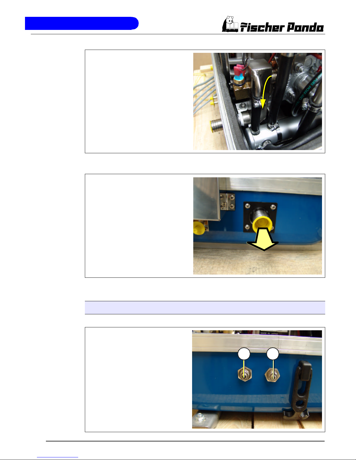
Exhaust elbow
After the combustion air was led through
the engine it occurs into the water-cooled
exhaust elbow. On the top side the pipe
union for the internal raw water circle is to
be seen.
Fig. A.24: Exhaust elbow
Exhaust outlet
Connect the exhaust pipe with the water
lock.
Fig. A.25: Exhaust outlet
A.2.6 Components of the Electrical System
Connection starter battery
Connect here the cables of the starter
battery.
1. Cable starter battery minus (-)
2. Cable starter battery plus (+)
Fig. A.26: Connection starter battery
1 2
Page 24
The Panda Generator
Page 18 Panda PMS AGT-DC 4000 - 24V - Chapter A: The Panda Generator
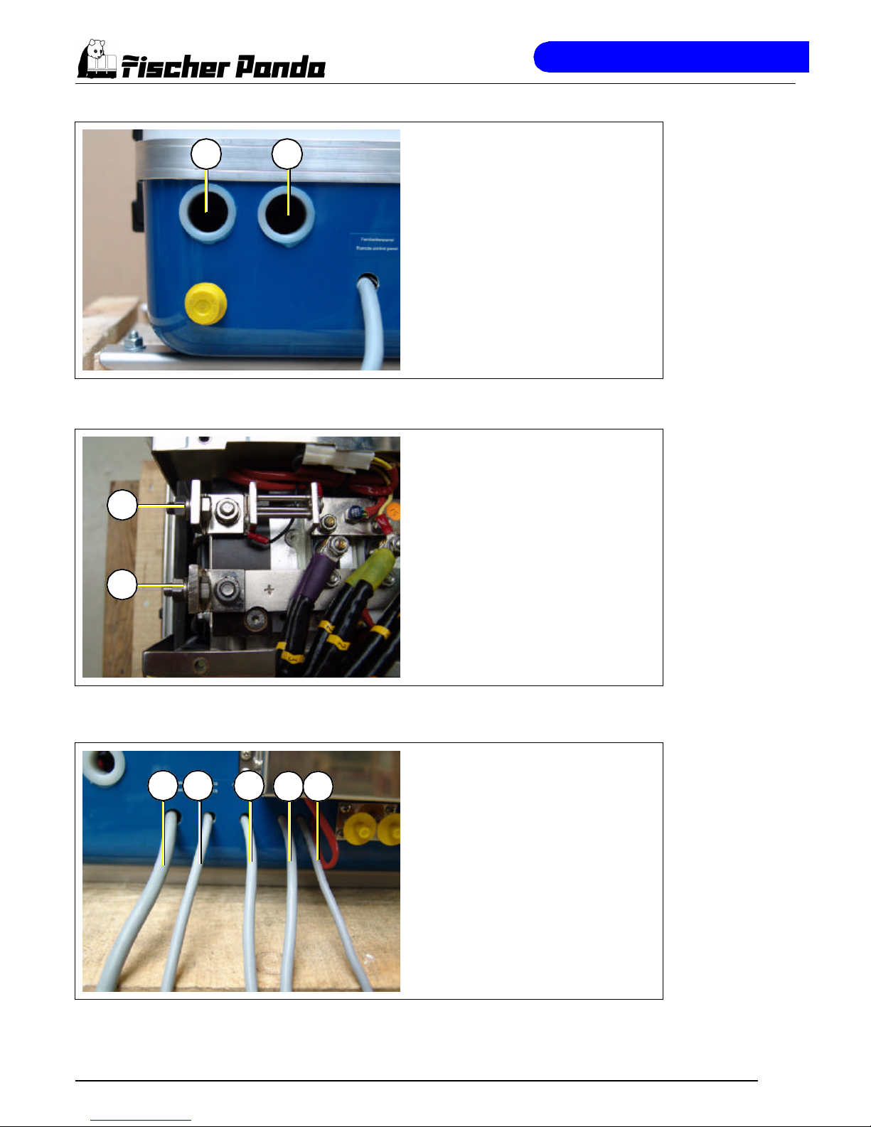
Passage for battery cable
The battery cables of the battery bank
must be laid through this passage to the
clamps at the diode plate.
Fig. A.27: Passage
Clamps for battery cable
1. Clmap (+) for battery cable (+)
2. Clamp (-) for battery cable (-)
Fig. A.28: Connections battery cable
Electrical connection for control
At the front of the generator also all
remaining cables for the electrical connections are depending upon type. See
here:
1. Remote control panel
2. VCS
3. Fuel pump
4. Voltage sense 24V
5. Shunt
Fig. A.29: Electrical connections
1 2
1
2
4
31 2
5
Page 25
The Panda Generator
Panda PMS AGT-DC 4000 - 24V - Chapter A: The Panda Generator Page 19
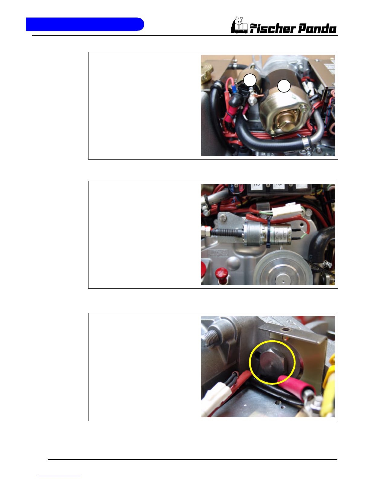
Starter motor
1. Starter motor and
2. Solenoid switch
The Diesel engine is electrically started.
On the top of the engine is accordingly the
electrical starter with the solenoid switch.
Fig. A.30: Starter motor
Actuator for speed regulation
The generator voltage is determined by
progressive speed control through "VCS"
in conjunction with the speed actuator.
Speed increases with increasing load.
Fig. A.31: Actuator
Plug for speed sensor
All Panda generators can be equipped
with an external automatic start. For the
operation of this automatic starting system
a separate speed sensor is necessary. At
some models the speed sensor is standard installed.
Fig. A.32: Plug for speed sensor
1
2
Page 26
The Panda Generator
Page 20 Panda PMS AGT-DC 4000 - 24V - Chapter A: The Panda Generator
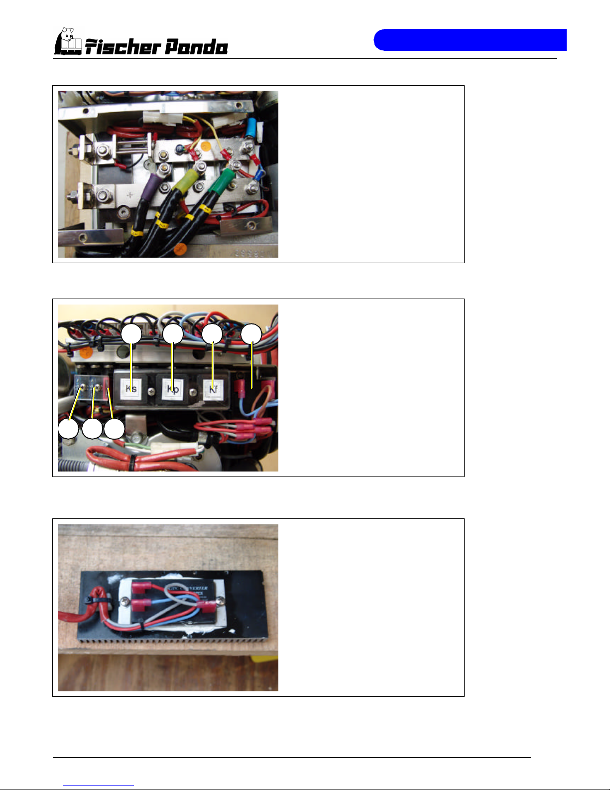
Diode plate
Fig. A.33: Diode plate
Terminal block for remote control
panel, fuses and relays
F1 fuse 15A for release relay
F2 fuse 15A for DC-system
F2 fuse 10A for AC-system
Ks relay for starter motor
K2 relay for plow plug
K3 relay for fuel pump
K4 Release relay
Fig. A.34: Terminal block
DC/DC-converter
Fig. A.35: DC&DC/converter
F1 F2
Ks K2
K3
F3
K4
Page 27
The Panda Generator
Panda PMS AGT-DC 4000 - 24V - Chapter A: The Panda Generator Page 21
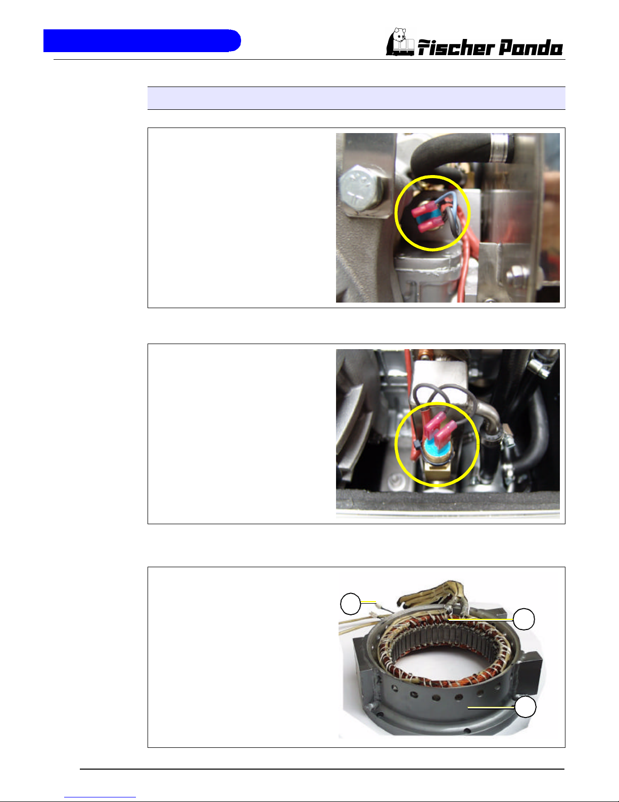
A.2.7 Sensors and switches for operating surveillance
Thermo-switch at engine
The thermo-switch at the engine is used
for monitoring the engine temperature.
Fig. A.36: Thermo.switch at engine
Thermo-switch at exhaust connection
If the impeller pump drop out and deliveres no more seawater, the exhaust connection becomes extremely hot.
Fig. A.37: Thermo-switch at exhaust connection
Thermo-switch coil
1. Thermo-switch coil 125°C
2. Generator housing
3. Thermo-sensor NTC 981S
(for measuring)
Fig. A.38: Thermo-switch coil
1
2
3
Page 28
The Panda Generator
Page 22 Panda PMS AGT-DC 4000 - 24V - Chapter A: The Panda Generator
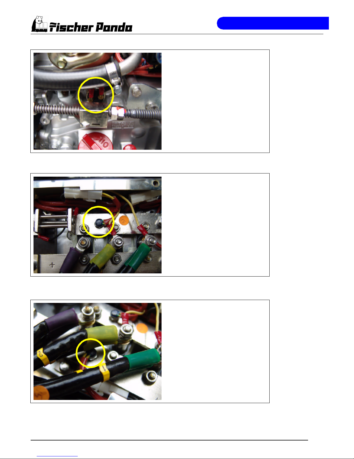
Oil pressure switch
In order to be able to monitore the lubricating oil system, an oil pressure switch is
built into the system.
Fig. A.39: Oil pressure switch
Thermo-switch on the (-)-bar
Fig. A.40: Thermo-switch on the (-)-bar
Thermo-switch on the (+)-bar
Fig. A.41: Thermo-switch on the (+)-bar
Page 29
The Panda Generator
Panda PMS AGT-DC 4000 - 24V - Chapter A: The Panda Generator Page 23
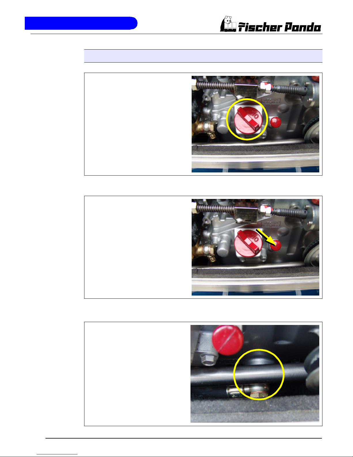
A.2.8 Components of the Oil Circuit
Oil filler neck with cap
Please pay attention that the filler necks
are always well locked after filling in
engine oil.
Consider also the references to the
engine oil specification.
Fig. A.42: Oil filler neck
Oil dipstick
At the dipstick the permissible level is indicated by the markings "maximum" and
"minimum". The engine oil should be
never filled up beyond the maximum conditions.
Fig. A.43: Oil dipstick
Oil strainer
The oil strainer should be cleaned every
500 operating hours.
Fig. A.44: Oil srtainer
Page 30
The Panda Generator
Page 24 Panda PMS AGT-DC 4000 - 24V - Chapter A: The Panda Generator
Oil drain hose
The Panda generator is equipped that the
engine oil can be drained over an drain
hose. The generator should be always
installed therefore that a collecting basin
can be set up deeply enough. If this is not
possible, an electrical oil drain pump must
be installed.
Note: Lubricating oil should be drained
in the warm condition!
Fig. A.45: Oil drain hose
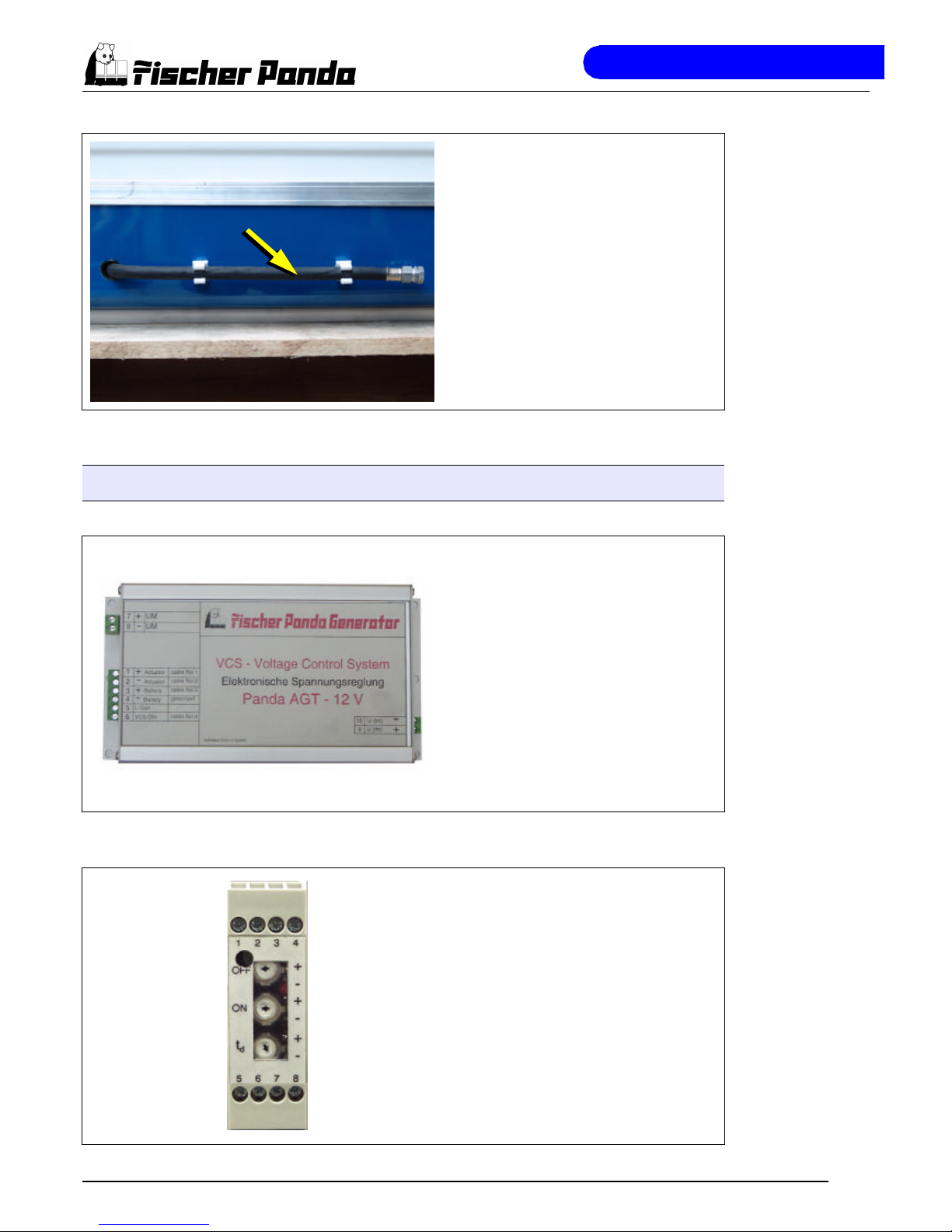
A.2.9 External Components
Voltage control VCS
The figure shows the control printed board
for the VCS voltage regulation. Over this
control printed board the control signals
are given for the actuator for speed regulation. On the VCS board are also adjustment possibilities for the control
parameters.
Fig. A.46: VCS
Battery monitor
Fig. A.47: Battery monitor
Page 31

The Panda Generator
Panda PMS AGT-DC 4000 - 24V - Chapter A: The Panda Generator Page 25
A.3 Operation Instructions
A.3.1 Daily routine checks before starting
1. Oil Level Control (ideal level: MAX).
AtTTENTION! OIL PRESSURE CONTROL!
True, the diesel motor automatically switches off when there is a lack of oil, but it is very damaging for the motor, if
the oil level drops to the lowest limit. Air can be sucked in suddenly when the boat rocks in heavy seas, if the oil
level is at a minimum. This affects the grease in the bearings. It is therefore necessary to check the oil level daily
before initially running the generator. The oil level must be topped up to the maximum level, if the level drops below
the mark between maximum und minimum levels.
2. State of Cooling Water.
The external compensation tank should be filled up to a maximum of in a cold state. It is very important that large
expansion area remains above the cooling water level.
3. Open Sea Cock for Cooling Water Intake.
For safety reasons, the seacock must be closed after the generator has been switched off. It should be re-opened
before starting the generator.
4. Check Seawater Filter.
The seawater filter must be regularly checked and cleaned. The impeller fatigue increases, if residual affects the
seawater intake.
5. Check all Hose Connections and Hose Clamps are Leakage.
Leaks at hose connections must be immediately repaired, especially the seawater impeller pump. It is certainly
possible that the seawater impeller pump will produce leaks, depending upon the situation. (This can be caused by
sand particles in the seawater etc.) In this case, immediately exchange the pump, because the dripping water will
be sprayed by the belt pulley into the sound insulated casing and can quickly cause corrosion.
6. Check all electrical Lead Terminal Contacts are Firm.
This is especially the case with the temperature switch contacts, which automatically switch off the generator in
case of faults. There is only safety if these systems are regularly checked, and these systems will protect the generator, when there is a fault.
7. Check the Motor and Generator Mounting Screws are Tight.
The mounting screws must be checked regularly to ensure the generator is safe. A visual check of these screws
must be made, when the oil level is checked.
8. Switch the Land Electricity/Generator Switch to Zero before Starting or Switch Off all the Consumers.
The generator should only be started when all the consumers have been switched off. The excitation of the generator will be suppressed, if the generator is switched off with consumers connected, left for a while, or switched on
with extra load, thus reducing the residual magnetism necessary for excitation of the generator to a minimum. In
certain circumstances, this can lead to the generator being re-excitated by means of a DC source. If the generator
does not excitate itself when starting, then excitation by means of DC must be carried out again.
9. Check the Automatic Controls Functions and Oil Pressure.
Removing a cable end from the monitoring switch carries out this control test. The generator should then automatically switch off. Please adhere to the inspection timetable (see Checklist in the appendix).
Page 32

The Panda Generator
Page 26 Panda PMS AGT-DC 4000 - 24V - Chapter A: The Panda Generator
A.3.2 Starting Generator
1. If necessary, open the fuel valve.
2. If necessary, close the main battery switch.
3. Check if all the consumers have been switched off.
The consumers are switched off, before the generator is switched off. The generator is not to be started with consumers connected. If necessary, the main switch or fuse should be switched off or the consumers should be individually switched off.
4. Press „ON“ button.
If an automatic start is requested during the switching on process, the generator is started and the panel switches
to automatic mode; if there is no automatic start request, the panel switches to delay mode.
5. Press „START“ button.
Press the "START"-button for a short period. The generator is started automatically. As soon as the motor turns
over, the starter switches off automatically. It must be monitored every time it is started. The generator must be
immediately switched off if the starter is still audible after the engine revs up.
The "START"-button fulfills several functions in the different operation modes of the panel:
If the panel is in delay mode, the generator is started and the panel switches to manual mode, that means the
automatic stop functions are not carried out. If the "AGT"-generator is started manually, it must be stoped manually,
too. In this case there is no automatic stop!
In the manual mode, the generator continues to run and the panel switches to automatic mode, that means if the
last automatic start programm is dispensed with, the generator is stopped and the panel switches to delay mode; if
there is no automatic start programm, the generator is stopped and the panel switches to delay mode.
6. Check coolant flow.
Immediately after starting it must be checked whether sufficient coolant flows out at the exhaust.
7. Check electrical voltage.
In order protect the electrical system, especially the onboard batteries from being damaged, the generator voltage
must be continually monitored (Voltmeter).
An automatic voltage monitor should be installed, which switches the generator off when overvoltage or undervoltage occurs or sounds an alarm.
A.3.3 Stopping the Generator
1. The generator can only be switched off at the remote control panel by use of the "ON/OFF"switch during manual operation.
2. During automatic operation the generator can also be switched off by use of the remote control "ON/OFF"-switch or by opening the switch contact for automatic control (also see circuit
diagram).
In cases of emergency the generator can be stopped by using the decompression lever.
 Loading...