

FISCHER DA01 VUW, DA01 VUW ATEX, DA03 0A Series, DA03 1C Series, DA03 1B Series Operating Manual
...Page 1
Operating manual
DA01 VUW
Differential pressure measuring device
Pressure levels PN250/PN400
Standard version
09015042 • BA_EN_DA01_VUW • Rev. ST4-A • 02/18
*09015042*
Page 2

| Masthead FISCHER Mess- und Regeltechnik GmbH
Masthead
Manufacturer:
Technical editorial team:
FISCHER Mess- und Regeltechnik GmbH
Bielefelderstr. 37a
D-32107 Bad Salzuflen
Telefon: +49 5222 974 0
Telefax: +49 5222 7170
eMail: info@fischermesstechnik.de
web: www.fischermesstechnik.de
Documentation representative: S. Richter
Technical editor: R.Kleemann
All rights, also those to the translation, reserved. No part of these instructions
may be reproduced or processed, duplicated or distributed using electronic systems or any other form (print, photocopy, microfilm or another process) without
the written consent of the company FISCHER Mess- und Regeltechnik GmbH,
Bad Salzuflen.
Reproduction for internal use is expressly allowed.
Brand names and procedures are used for information purposes only and do
not take the respective patent situation into account. Great care was taken
when compiling the texts and illustrations; nevertheless, errors cannot be ruled
out. The company FISCHER Mess- und Regeltechnik GmbH will not accept any
legal responsibility or liability for this.
Subject to technical amendments.
© FISCHER Mess- und Regeltechnik 2018
Version history
Rev. ST4-A 11/15 Version 1 (first edition)
2 / 32 BA_EN_DA01_VUW
Page 3

FISCHER Mess- und Regeltechnik GmbH Table of Contents
Table of Contents
1 Sicherheitshinweise ....................................................................................................................................... 4
1.1 General .....................................................................................................................................................4
1.2 Personnel Qualification.............................................................................................................................4
1.3 Risks due to Non-Observance of Safety Instructions ...............................................................................4
1.4 Safety Instructions for the Operating Company and the Operator............................................................4
1.5 Unauthorised Modification ........................................................................................................................4
1.6 Inadmissible Modes of Operation .............................................................................................................4
1.7 Safe working practices for maintenance and installation work .................................................................5
1.8 Pictogram explanation ..............................................................................................................................5
2 Product and functional description ..............................................................................................................6
2.1 Delivery scope ..........................................................................................................................................6
2.2 Equipment versions ..................................................................................................................................6
2.3 Function diagram ....................................................................................................................................11
2.4 Design and mode of operation................................................................................................................11
3 Assembly.......................................................................................................................................................12
3.1 General information ................................................................................................................................12
3.2 Process connection ................................................................................................................................12
3.3 Electrical connections .............................................................................................................................13
4 Commissioning.............................................................................................................................................15
4.1 General ...................................................................................................................................................15
4.2 Venting of the pressure lines ..................................................................................................................15
4.3 Zero point correction...............................................................................................................................16
4.4 Switch point setting.................................................................................................................................16
5 Servicing .......................................................................................................................................................17
5.1 Maintenance ...........................................................................................................................................17
5.2 Transport ................................................................................................................................................17
5.3 Service....................................................................................................................................................17
5.4 Disposal ..................................................................................................................................................17
6 Technical Data .............................................................................................................................................. 18
6.1 Allgemeines ............................................................................................................................................18
6.2 Input variables ........................................................................................................................................19
6.3 Operating conditions...............................................................................................................................19
6.4 Construction design ................................................................................................................................20
7 Order Codes..................................................................................................................................................27
7.1 accessories.............................................................................................................................................29
8 EU Declarations of conformity ....................................................................................................................30
9 EAC Declaration ...........................................................................................................................................32
BA_EN_DA01_VUW 3 / 32
Page 4

1 | Sicherheitshinweise FISCHER Mess- und Regeltechnik GmbH
1 Sicherheitshinweise
1.1 General
WARNING
This operating manual contains instructions fundamental to the installation, operation and maintenance of the device that must be observed unconditionally. It
must be read by the assembler, operator and the specialized personnel in
charge of the instrument before it is installed and put into operation.
This operating manual is an integral part of the product and therefore needs to
be kept close to the instrument in a place that is accessible at all times to the responsible personnel.
The following sections, in particular instructions about the assembly, commissioning and maintenance, contain important information, non-observance of
which could pose a threat to humans, animals, the environment and property.
The instrument described in these operating instructions is designed and manufactured in line with the state of the art and good engineering practice.
1.2 Personnel Qualification
The instrument may only be installed and commissioned by specialized personnel familiar with the installation, commissioning and operation of this product.
Specialized personnel are persons who can assess the work they have been
assigned and recognize potential dangers by virtue of their specialized training,
their skills and experience and their knowledge of the pertinent standards.
1.3 Risks due to Non-Observance of Safety Instructions
Non-observance of these safety instructions, the intended use of the device or
the limit values given in the technical specifications can be hazardous or cause
harm to persons, the environment or the plant itself.
The supplier of the equipment will not be liable for damage claims if this should
happen.
1.4 Safety Instructions for the Operating Company and the Operator
The safety instructions governing correct operation of theinstrument must be
observed. The operating company must make them available to the installation,
maintenance, inspection and operating personnel.
Dangers arising from electrical components, energy discharged by the medium,
escaping medium and incorrect installation of the device must be eliminated.
See the information in the applicable national and international regulations.
Please observe the information about certification and approvals in the Technical Data section.
1.5 Unauthorised Modification
Modifications of or other technical alterations to the instrument by the customer
are not permitted. This also applies to replacement parts. Only the manufacturer
is authorised to make any modifications or changes.
1.6 Inadmissible Modes of Operation
The operational safety of this instrument can only be guaranteed if it is used as
intended. The instrument model must be suitable for the medium used in the
system. The limit values given in the technical data may not be exceeded.
The manufacturer is not liable for damage resulting from improper or incorrect
use.
4 / 32 BA_EN_DA01_VUW
Page 5
FISCHER Mess- und Regeltechnik GmbH Sicherheitshinweise | 1
1.7 Safe working practices for maintenance and installation work
The safety instructions given in this operating manual, any nationally applicable
regulations on accident prevention and any of the operating company's internal
work, operating and safety guidelines must be observed.
The operating company is responsible for ensuring that all required maintenance, inspection and installation work is carried out by qualified specialized personnel.
1.8 Pictogram explanation
DANGER
Type and source of danger
This indicates a direct dangerous situation that could lead to death or serious
injury (highest danger level).
a) Avoid danger by observing the valid safety regulations.
WARNING
Type and source of danger
This indicates a potentially dangerous situation that could lead to death or serious injury (medium danger level).
a) Avoid danger by observing the valid safety regulations.
CAUTION
Type and source of danger
This indicates a potentially dangerous situation that could lead to slight or serious injury, damage or environmental pollution (low danger level).
a) Avoid danger by observing the valid safety regulations.
NOTICE
Note / advice
This indicates useful information of advice for efficient and smooth operation.
BA_EN_DA01_VUW 5 / 32
Page 6

2 | Product and functional description FISCHER Mess- und Regeltechnik GmbH
Large measuring cell Ø130 Small measuring cell Ø75
NG100
NG160
(mbar ranges) (bar ranges)
1/4-18 NPT
1/2-14 NPT
1/4-18 NPT
1/2-14 NPT
Inner thread Outer thread Cutting ring-
screw connection
12 mm tube
Flange connection
based on DIN 615018
with internal thread G½
G½ G½ G½ G½
G½
2 Product and functional description
2.1 Delivery scope
• Differential pressure measuring device DA01
• Operating Manual
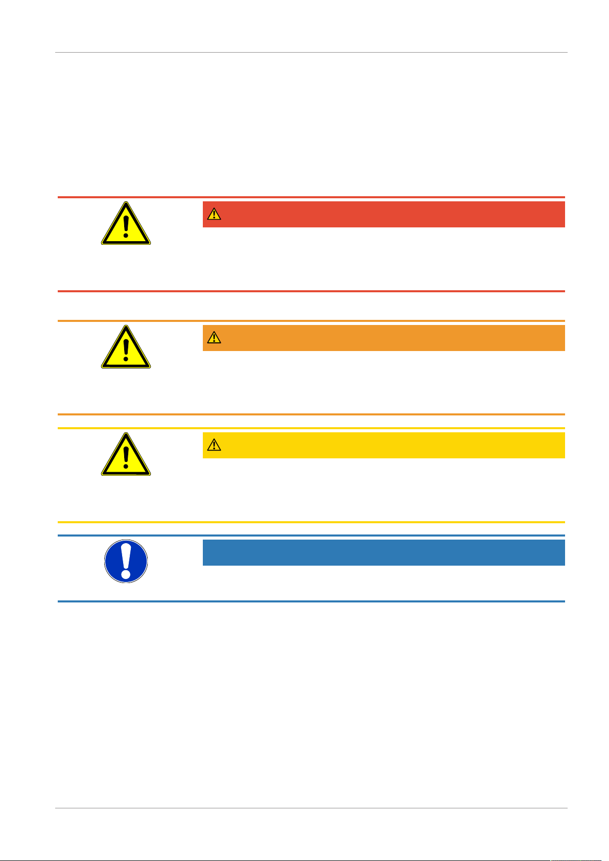
2.2 Equipment versions
The following illustrations depict typical combinations of the measuring cell,
measured value display and contact elements. However, these can be freely
combined according to the order code. Wherever this is not possible, this is
clearly stated.
For instance, a small measuring cell with an NG160 display and a contact element is also available.
Fig.1: Device overview
2.2.1 Process connection
Fig.2: Options for the process connection
6 / 32 BA_EN_DA01_VUW
Page 7
FISCHER Mess- und Regeltechnik GmbH Product and functional description | 2
Low-action contacts
Snap-actiocontacts
Inductive contacts
KINAX 3W2 708-226D0
KINAX 3W2 708-226E0
for standard devices
Snap-action contacts
Inductive contacts
for ATEX devices
KINAX 3W2 708-226D0
KINAX 3W2 708-226E0
Rotation angle encoder in accordance
with data sheet KE09
Limit switch in accordance with
data sheet KE##
Marker needle
Trailing needle
Fluid fillings
Unit without contacts
Paraffin oil, glycerine, silicon oil
Unit with inductive contacts
Paraffin oil, silicon oil
Unit with low-action contacts
Paraffin oil, silicon oil
Units with magnetic spring contacts
Silicon oil
2.2.2 Nameplate
2.2.3 Contact elements
Fig.3: Contact elements
2.2.4 Special functions
Fig.4: Special functions
BA_EN_DA01_VUW 7 / 32
Page 8

2 | Product and functional description FISCHER Mess- und Regeltechnik GmbH
Wall mounting Pipe mounting
Panel mounting set type 1 Panel mounting set type 2
with panel mounting set with front ring
available
on request
2.2.5 Assembly
Fig.5: Assembly
The panel installation fittings can only be used in devices with a small measuring cell (Ø75) and a display in the NG100 bayonet ring casing.
WARNING
Panel mounting set
Due to the heavy weight, the operator needs to install a support construction for
installation of the front panel.
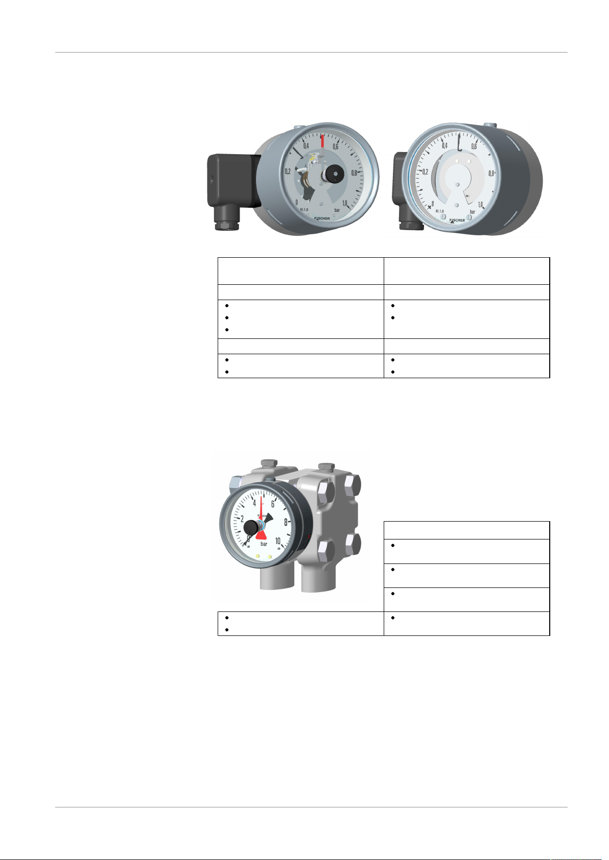
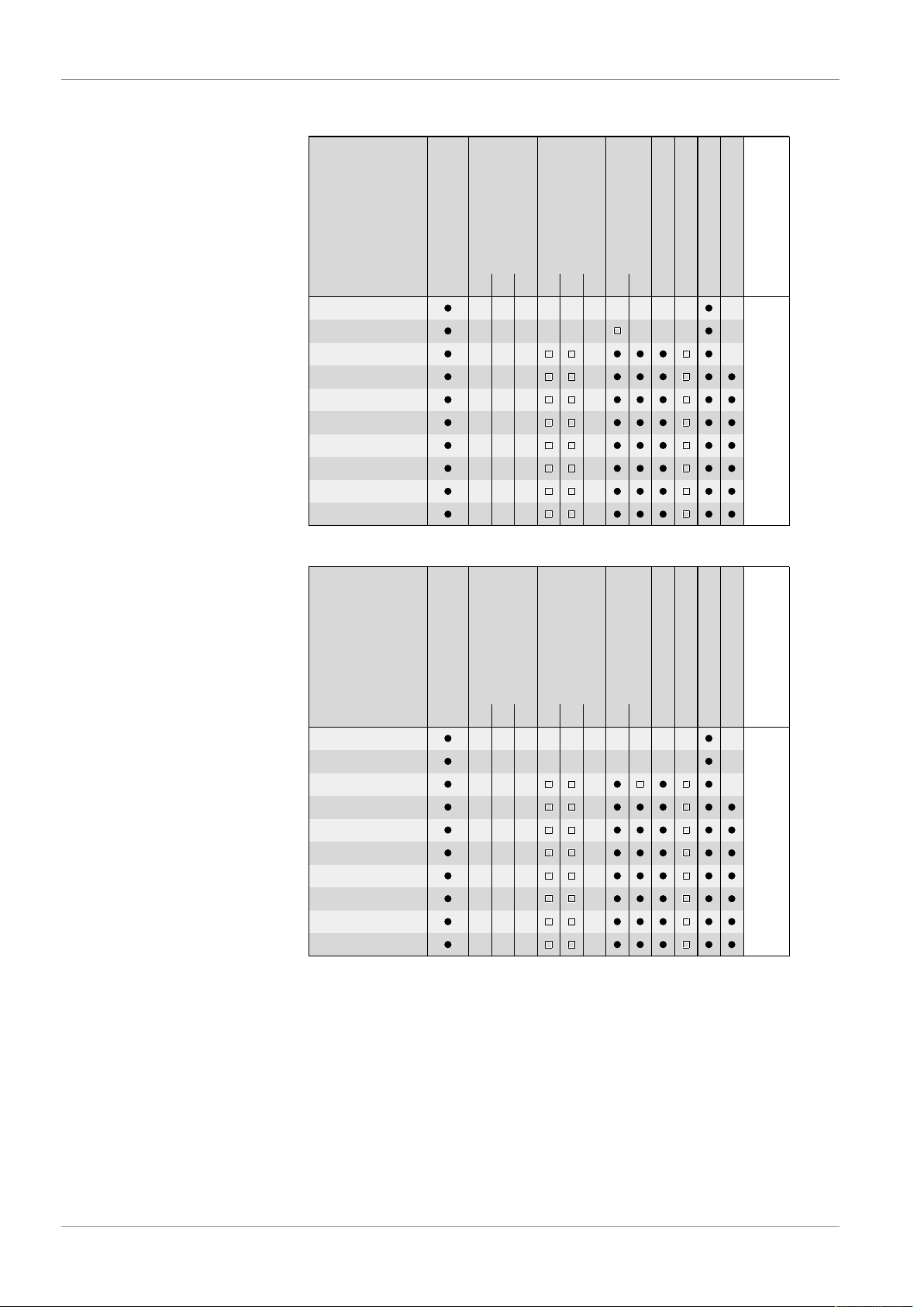
2.2.6 Equipment features (overview)
The following shows the configuration possibilities of the DA01 depending on
the measuring cell used and the pressure level.
Key
8 / 32 BA_EN_DA01_VUW
Page 9
FISCHER Mess- und Regeltechnik GmbH Product and functional description | 2
Measuring range
Measured value display
Ø100
Inductive contacts
Rotation angle transducer
Trailing needle
Marker needle
Remote seal
1 2 3 1 2
0 ... 0.6 bar
0 ... 1 bar
0 ... 1.6 bar
0 ... 2.5 bar
0 ... 4.0 bar
0 ... 6bar
0 ... 10 bar
0 ... 16 bar
0 ... 25 bar
-1 ... 0.6 bar
-1 ... 1.5 bar
-1 ... 3 bar
Snap-action contacts
-1 ... 5 bar
1 2 3
Low-action contacts
Pressure levelPN250/PN400
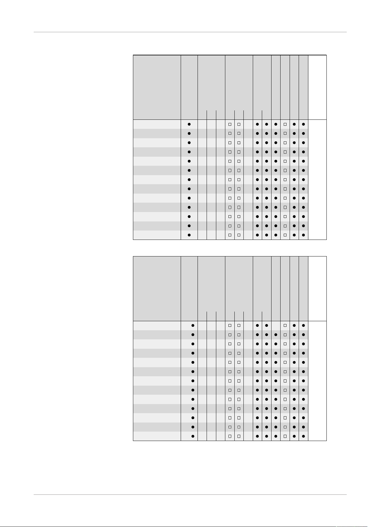
Measuring range
Measured value display
Ø160
Inductive contacts
Rotation angle transducer
Trailing needle
Marker needle
Remote seal
1 2 3 1 2
0 ... 0.6 bar
0 ... 1 bar
0 ... 1.6 bar
0 ... 2.5 bar
0 ... 4.0 bar
0 ... 6bar
0 ... 10 bar
0 ... 16 bar
0 ... 25 bar
-1 ... 0.6 bar
-1 ... 1.5 bar
-1 ... 3 bar
Snap-action contacts
-1 ... 5 bar
1 2 3
Low-action contacts
Pressure levelPN250/PN400
Small measuring cell Ø75
BA_EN_DA01_VUW 9 / 32
Fig.6: Small measuring cell Ø75 Measured value display Ø100
Fig.7: Small measuring cell Ø75 Measured value display Ø160
Page 10
2 | Product and functional description FISCHER Mess- und Regeltechnik GmbH
-100 ... +250 mbar
Measuring range
Inductive contacts
Rotation angle transducer
Trailing needle
Marker needle
Remote seal
1 2 3 1 2
0 ... 40 mbar
0 ... 60 mbar
0 ... 100 mbar
0 ... 160 mbar
0 ... 250 mbar
0 ... 400 mbar
-40 ... +60 mbar
-60 ... +100 mbar
-100 ... +150 mbar
Snap-action contacts
1 2 3
Low-action contacts
Pressure level
PN250
Measured value display
Ø100
-100 ... +250 mbar
Measuring range
Inductive contacts
Rotation angle transducer
Trailing needle
Marker needle
Remote seal
1 2 3 1 2
0 ... 40 mbar
0 ... 60 mbar
0 ... 100 mbar
0 ... 160 mbar
0 ... 250 mbar
0 ... 400 mbar
-40 ... +60 mbar
-60 ... +100 mbar
-100 ... +150 mbar
Snap-action contacts
1 2 3
Low-action contacts
Pressure level
PN250
Measured value display
Ø160
Large measuring cell Ø130
Fig.8: Large measuring cell Ø130 Measured value display Ø100
Fig.9: Large measuring cell Ø130 Measured value display Ø160
10 / 32 BA_EN_DA01_VUW
Page 11

FISCHER Mess- und Regeltechnik GmbH Product and functional description | 2
1
2
3
4
5
6
7
8
8
7
2.3 Function diagram
Fig.10: Function diagram
1 Motion train 2 Transfer lever
3 Measuring shaft 4 Pressure transfer fluid
5 Separating membrane 6 Connecting rod
7 Measuring diaphragm 8 Pressure chamber
2.4 Design and mode of operation
The pressures in the pressure chambers that are to be compared are each exerted onto a measuring membrane that can be rigidly connected using a connection rod. To compensate the static pressure, the space between the separating and measuring membrane is filled with a pressure transfer fluid.
During pressure equalisation, the two measuring membranes are in an idle position. In case of pressure difference, the force acting on the membranes causes
it to be moved towards the side of the lower pressure.
The connecting rod transfers the deflection of the measuring membranes onto
the transfer lever mounted to the measuring shaft. Proportional to the current
differential pressure, the measurement shaft makes a rotational movement that
the indicator translates into a rotation angle between 0 and 270°.
In the case of one-sided pressure by the measuring system above and beyond
the measuring range, the over-pressure guard will be activated which supports
the overlosaded membrane.
BA_EN_DA01_VUW 11 / 32
Page 12

3 | Assembly FISCHER Mess- und Regeltechnik GmbH
3 Assembly
3.1 General information
The device can be mounted in one of the following ways (see Assembly):
1. Wall mounting
The device is designed for installation onto flat assembly plates. The unit is
equipped with a wall mounting plate for this mounting type.
2. Pipe assembly
The device is equipped with a special pipe assembly set and is suitable for
mounting to a 2" pipe (DN50).
3. Panel mounting
Panel mounting is available in two installation models.
– Panel mounting fittings (Type 1)
This variant is only suitable for models with a small measuring system
(Ø75) and a bayonet ring casing NG100.
– Panel installation with front ring (Type 2)
All models are suitable for this variant. A suitable steel construction
must be used to ensure that the front plate can bear the weight of the
DA03. This is possible e.g. by means of a combination with the wall or
pipe assembly.
At the factory, the device is calibrated for vertical installation, but the installation
position is arbitrary. For any installation positions that are not vertical, the zeropoint signal can be corrected via the installed offset correction.
To ensure safety during installation and maintenance, we recommend installing
a suitable shut-off valve on the system (see accessories).
3.2 Process connection
• By authorized and qualified specialized personnel only.
• The pipes need to be depressurized when the instrument is being connected.
• Appropriate steps must be taken to protect the device from pressure surges.
• Check that the device is suitable for the medium being measured.
• Maximum pressures must be observed (cf. Tech. data)
All supply lines are arranged so that there are no mechanical forces acting on
the device.
The pressure lines must be kept as short as possible and installed without any
tight bends to avoid delays.
The pressure lines must be installed at an inclination so that when fluids are
measured no air pockets are created or when measuring gases, no water pockets are created. If the required inclination is not reached, water or air filters must
be installed at suitable places.
The pressure lines need to be vented for fluid measuring media. [}15].
If water is used as a measuring medium, the unit must be protected against
frost.
If the pressure sensing lines are already pressurised at the time of commissioning, zero-point control and adjustment cannot be performed. In such cases, the
device should be only connected to the mains without the pressure sensing
lines.
12 / 32 BA_EN_DA01_VUW
Page 13

FISCHER Mess- und Regeltechnik GmbH Assembly | 3
+
Higher pressure
lower pressure
1
2
3
4
5
6
M20 x 1.5
1
2
5
6
3
4
4
The process connections are marked with (+) and (-) symbols on the device.
The pressure lines must be mounted according to these symbols.
Differential pressure
Fig.11: Process connection
3.3 Electrical connections
• By authorized and qualified specialized personnel only.
• When connecting the unit, the national and international electro-technical
regulations must be observed.
• Disconnect the system from the mains, before electrically connecting the
device.
• Install the consumer-adapted fuses.
• Do not connect the connector if strained.
Only devices with contact elements are connected to the electrical supply. To
this end there is a cable socket on the side of the device, or a HAN plug in the
power plant version.
3.3.1 Cable socket / HAN plug
BA_EN_DA01_VUW 13 / 32
Fig.12: Cable socket
1 Lower part 2 Sealing ring EPDM
3 Middle part 4 Sealing ring EPDM
5 Lid 6 Lid screw
Fig.13: HAN connector
1 Cable screw connection M20 x 1.5 2 Sleeve housing Han 3A
3 Socket insert Han 7D 4 Pin insert Han 7D
5 Safety clip 6 Attachment casing Han 3D
Page 14

3 | Assembly FISCHER Mess- und Regeltechnik GmbH
1 2 3 4
1 2
1 2 3 4
1 2 3
1 2 3 4
-+-
+
1 2
Eb= 5 ... 25V
1 2 3
R
L
+
-
Eb= 12 ... 30V
1 2 3
R
L
+
-
~
+
-
~
+
-
2-Wire 3-Wire
3.3.2 Contact elements
Contact elements are supplied in accordance with data sheet KE. This illustrates all variants, their pin assignment and the technical data.
Creep and magnetic spring contacts
The terminal numbers always correspond to the contact number an are assigned to the target indicators from left to right. Up to three contacts can be
used. There are assigned to the target indicators as follows:
1. For 2 contacts
Contact 1: left target indicator
Contact 2:right target indicator
2. For 3 contacts
Contact 1: left target
Fig.14: Contacts
Contact 2: middle target
Contact 3: right target
Inductive contacts
In the case of inductive contacts, the switch function is not only determined by
the slot type initiator but also by the switch amplifier. Up to max two contacts
can be used. There are assigned to the target indicators as follows:
Contact 1: left target indicator
Fig.15: Inductive contacts
Contact 2:right target indicator.
3.3.3 Rotation angle transducers KINAX 3W2
The rotation angle encoder serves to record angular positions, to prepare and
provide the measured values as electrical output signals 0/4…20mA for the
following device. Rotation angle encoder is supplied in accordance with data
sheet KE09. This contains further information about the pin assignment and the
technical data.
Fig.16: Rotation angle transducers connection
14 / 32 BA_EN_DA01_VUW
Page 15

FISCHER Mess- und Regeltechnik GmbH Commissioning | 4
Venting screw
Closing screw0.8 x 4
Venting screws
5
Seal (FKM)
4 Commissioning
4.1 General
All electrical supply, operating and measuring lines, and the pressure connections must have been correctly installed before commissioning. All supply lines
are arranged so that there are no mechanical forces acting on the device.
Check that all pressure connections are free of leaks before commissioning.
In models filled with fluid, the venting valve on the upper side of the bayonet
casing must be opened before commissioning! To do this, turn the venting
screw anticlockwise as far as it will go.
Fig.17: Venting valve
4.2 Venting of the pressure lines
WARNING
Risk connected to pressure
Never remove the venting screw if the unit is still pressurised! Close the shut-off
valves of the flanged fittings or depressurize the system.
The pressure lines need to be vented for before commissioning on devices that
work with fluid media. Proceed as follows:
• Remove the venting screws of the two pressure chambers.
• Carefully increase the system pressure until the fluid level is 5 mm below
the sealing surface of the threaded borehole.
• Close the device with the venting screws
Fig.18: Venting with fluid media
BA_EN_DA01_VUW 15 / 32
Page 16

4 | Commissioning FISCHER Mess- und Regeltechnik GmbH
Without fluid filling With fluid filling
Closing screw 11
1.2 x 7
1
2
3
4
5
6
4.3 Zero point correction
The differential pressure measuring units are set in the factory before delivery
so that they do not usually need to be adjusted at the assembly site. If this is
still necessary, proceed as follows:
• Depressurize the measuring chamber (+) und (-) side or only exert the existing static system pressure.
• Remove the closing screw The zero point correction screw is located behind.
• Set the measurement value pointer to the scale zero point using the zero
point correction screw.
• Mount the closing screw
Fig.19: Zero point correction screw
4.4 Switch point setting
There is an adjustment lock attached to the front pane of the measuring unit on
units with contact elements. This means that the contacts attached to the target
indicators can be set to any point along the scale.
To facilitate switching precision and the service life of the mechanical measuring system, the switching points should lie between 10% and 90% of the measuring range.
Fig.20: Switch point setting
1 Adjustment key 2 Adjusting lock
3 Axle 4 Drive arm
5 Set-point display 6 Actual value display
Adjustment sequence:
16 / 32 BA_EN_DA01_VUW
• Press the axle inwards until the drive arm reaches behind the setting pin of
the target value indicator.
• Set the target value indicator to the required switch point by turning the setting key.
• Relieve the axle.
• The switch-point setting can be secured against unintentional adjustment by
removing the attachment screw and the adjustment key.
Page 17

FISCHER Mess- und Regeltechnik GmbH Servicing | 5
5 Servicing
5.1 Maintenance
The instrument is maintenance-free. We recommend the following regular inspection to guarantee reliable operation and a long service life:
• Check the function in combination with downstream components.
• Check the leak-tightness of the pressure connection lines.
• Check the electrical connections.
The exact test cycles need to be adapted to the operating and environmental
conditions. In combination with other devices, the operating instructions for the
other devices also need to be observed.
5.2 Transport
The measuring device must be protected against impacts. It should be transported in the original packaging or a suitable transport container.
5.3 Service
All defective or faulty devices should be sent directly to our repair department.
Please coordinate all shipments with our sales department.
WARNING
Process media residues
Process media residues in and ondismantled devices can be a hazard to
people, animals and the environment. Take adequate preventive measures. If
required, the devices must be cleaned thoroughly.
Return the device in the original packaging or a suitable transport container.
5.4 Disposal
WARNING
Incorrect disposal may pose a risk to the environment.
Please help to protect the environment by always disposing of the work pieces
and packaging materials in compliance with the valid national waste and recycling guidelines or reuse them.
BA_EN_DA01_VUW 17 / 32
Page 18

6 | Technical Data FISCHER Mess- und Regeltechnik GmbH
6 Technical Data
6.1 Allgemeines
EXECUTION Nominal
pressure
DA01 V … PN250 Ø75 Measuring ranges: 0…0.6 bar to 0…25 bar
DA01 U … PN400 Ø75 Measuring ranges: 0…0.6 bar to 0…25 bar
DA01 W … PN250 Ø130 Measuring ranges: 0…40 mbar to 0…400 bar
Measuring
cell
Application information
Remote seals:
It is possible to attach remote seals for all measuring ranges. The remote seals need to be designed for the displacement volume, the
length of the cable and the application temperature.
Remote seals:
It is possible to attach remote seals for all measuring ranges. The remote seals need to be designed for the displacement volume, the
length of the cable and the application temperature.
Limitations:
Drag indicator measuring ranges ≥ 60 mbar
Contacts / Transmitter measuring ranges ≥ 100 mbar
Remote seals:
It is possible to attach remote seals for measuring ranges ≥ 160 mbar.
The remote seals need to be designed for the displacement volume,
the length of the cable and the application temperature.
18 / 32 BA_EN_DA01_VUW
Page 19

FISCHER Mess- und Regeltechnik GmbH Technical Data | 6
6.2 Input variables
Measuring variable
Differential pressure in gaseous and fluid aggressive media.
General
Small measuring cell
Ø75
Rated pressure of the measuring
system
Durability One-sided over-pressure-proof up to the
Measurement accuracy ±1.6 % of the measuring range
Temperature sensor 0.3 % / 10 °C
Zero-point adjustment ±25 % of the measuring range
Max. static operating pressure
rated pressure of the measuring system
resistance to under-pressure on the (+) and
(-) side
Measuring ranges
Measuring range Device model
V U W
0 … 0.6 bar ● ●
0 … 1 bar ● ●
0 … 1.6 bar ● ●
0 … 2.5bar ● ●
0 … 4.0 bar ● ●
0 … 6 bar ● ●
0 … 10 bar ● ●
0 … 16 bar ● ●
0 … 25 bar ● ●
-1 … 0.6 bar ● ●
-1 … 1.5 bar ● ●
-1 … 3 bar ● ●
-1 … 5 bar ● ●
Large measuring cell
Ø130
Measuring range Device model
V U W
0 … 40 mbar ●
0 … 60 mbar ●
0 … 100 mbar ●
0 … 160 mbar ●
0 … 250 mbar ●
0 … 400 mbar ●
0 … 600 mbar ●
6.3 Operating conditions
Permissible ambient temperature -20 … +80 °C
Admissible storage temperature -40 … +80 °C
Admissible media temperature Max. 100 °C
Type of protection: IP 65 acc. to EN 60529
BA_EN_DA01_VUW 19 / 32
Page 20

6 | Technical Data FISCHER Mess- und Regeltechnik GmbH
6.4 Construction design
Materials
Measured value display Material Material no.
EU AISI
Bayonet ring housing NG100, NG160 CrNi steel 1.4301 304
Process connection (all models) CrNi steel 1.4404 316L
Intermediate plate AlMgSiPb HARD-COAT
Seals (O-rings) FKM
Motion train CrNi steel
Dial face and needle Aluminium, painted, printed
Inspection disk Safety laminated glass
®
MB = Measurement
range
Materials (media-contacting)
Design of the measuring system (R) Material Material no.
EU AISI
Pressure caps CrNi steel 1.4404 316L
Separation membranes CrNi steel 1.4571 361Ti
Design of the measuring system (G) Material Material no.
EU AISI
Pressure caps CrNi steel 1.4404 316L
Separation membranes Hastelloy® C276
Process connection Material Material no.
EU AISI
Connecting piece and port CrNi steel 1.4404 316L
Cutting ring screw connections CrNi steel 1.4571
Assembly
Wall mounting Flanged assembly plate
Pipe mounting Flanged assembly plate and attachment bracket
Panel mounting set
type 1
Panel mounting set
type 2
Panel installation fittings for units with a small measuring
cell (Ø75) and NG100 bayonet ring casing.
Front ring and support construction
20 / 32 BA_EN_DA01_VUW
Page 21

FISCHER Mess- und Regeltechnik GmbH Technical Data | 6
6.4.1 Additional Attachments
6.4.1.1 Contact elements
Limit signal transmitters (contacts) and capacitive rotation angle transducers
with an output signal proportional to the angular position can be fitted into a
housing augmented by a corresponding bayonet ring connector.
A certain minimum pressure level is required to operate this kind of contact element, which is why there is a lower limit for the mbar measuring ranges. This
limit depends on the model type and is stated in the section ‚General‘.
The measuring deviation increases by ±0.5% per contact when the contacts are
driven and switched.
For more information and the order key, please refer to the data sheet:
• for limit switch in data sheet KE
• for rotation angle converter in the data sheet KE09
6.4.1.2 Fluid charging
Under aggravated operating conditions, such as vibrations and extreme pressure fluctuations, or in order to avoid condensation forming if used outdoors, the
casing can be filled with the following fluids depending in the type of contacts installed:
without contacts Glycerine, silicon oil
Low-action contacts Silicon oil
Magnetic spring contacts Silicon oil
Inductive contacts Paraffin oil
Rotation angle transducer no filling possible
6.4.1.3 Marker needle
A settable red marker can be attached to the scale to clearly show a certain
pressure (limit value).
6.4.1.4 Trailing needle
The railing needle is 'dragged' with the measured value indicator. As there is no
fixed connection between the two needles, one-off maximum values are stored.
The trailing needle can be reset using an adjusting dial in the window. Trailing
needles cannot be used in conjunction with contacts. A certain minimum pressure level is required to move the drag indicator, which is why there is a lower
limit for the mbar measuring ranges. This limit depends on the model type and
is stated in the section ‚General‘.
6.4.1.5 Shut-off fitting
3-spindle valve block PN 100, DN 5, can be directly flanged
• Type DZ3600SV2700
• Material 1.4571
• Functions: Shut-off, pressure compensation
BA_EN_DA01_VUW 21 / 32
Page 22

6 | Technical Data FISCHER Mess- und Regeltechnik GmbH
Cable socket
HAN 7D
6.4.2 Electrical connection
In the case of devices with additional electronic equipment, the connection is
realised using a cable socket attached to the side and/or with a Han 7D connector on th epower plant models. The pin assignment depends on the ordered
mode and is stated in the data sheet KE or KE09.
Fig.21: Cable socket
Cable socket
Number of screw terminals 6 + 2PE
Rated current See data sheet KE
Rated voltage 250 V
Cable diameter up to 1.5 mm2 with wire protection
Cable screw connection M20 x 1.5, terminal range 7 … 13 mm
HAN 7D
No. of crimp contacts 7 + PE
Rated current See data sheet KE
Rated voltage 50 V
Cable diameter 1 mm
Cable screw connection M20 x 1.5, terminal range 7 … 13 mm
2
22 / 32 BA_EN_DA01_VUW
Page 23

FISCHER Mess- und Regeltechnik GmbH Technical Data | 6
Small measuring system (Ø75)
Flange based on DIN EN 61518 Wall mounting plate
152
105
90
80
86.5
132
(with installed contacts)
112
213
(with installed contacts)
165
113
NG100 Ø101
NG160 Ø161
Ø9
41.3
54.4
80
132
152
R6
Ø9
Cable socket
G½
7/16 UNF
Round steel bracket
2'' pipe (DN50)
2" pipe mounting
Pipe mounting plate
Spacer sleeve
Attachment kit for
round steel bracket
(possible for all models)
The pipe assembly set
is also available as accessory.
6.4.3 Dimensional drawings
All dimensions in mm unless otherwise stated
Fig.22: Dimensional drawing (Small measuring system Ø75)
Fig.23: Pipe mounting
BA_EN_DA01_VUW 23 / 32
Page 24

6 | Technical Data FISCHER Mess- und Regeltechnik GmbH
Wall mounting plate
Flange based on DIN EN 61518
Large measuring system (Ø130)
170
60
200
100
R6
Ø11
200
119
149
(with installed contacts)
170
60
120
Ø11
170
100
277.5
229.5
175
NG100 Ø101
NG160 Ø161
(with installed contacts)
7/16 UNF
G½
54.4
41.3
Cable socket
Installation of front panel type 1
d2
d1
d3
120°
d4
d1
NG100
d2 d3 d4
101 132 116 4.8
Front ring
Bayonet ring
with connecting bracket
Holding plate
Assembly bracket
The front plate thickness
must be min. 2 mm.
(only small measuring system Ø75 and NG100 display)
Fig.24: Dimensional drawing (Large measuring system Ø130)
Fig.25: Installation of front panel with panel fittings
24 / 32 BA_EN_DA01_VUW
Page 25

FISCHER Mess- und Regeltechnik GmbH Technical Data | 6
Installation of front panel type 2
Front ring
Bayonet ring
with connecting bracket
The front plate thickness must be min. 2 mm.
A suitable steel construction must be used to ensure
that the front plate can bear the weight of the DA03.
Examples:
d2
d1
d3
120°
d4
d1
NG100
NG160
d2 d3 d4
101 132 116 4.8
161 196 178 5.8
Assembly on a mounting plate Mounting to a 2'' pipe
Fig.26: Installation of front panel with front ring
BA_EN_DA01_VUW 25 / 32
Page 26

6 | Technical Data FISCHER Mess- und Regeltechnik GmbH
Contact elements
NG100 = 90
NG160 = 120
NG100 = 138
NG160 = 167.5
100 18 118
Shut-off fitting
~147
~155
Cutting ring connection G3/8
for 12 mm pipe
DA03
Process
1
2
3
2
13
~110
Valve open
108
54
(Connection clearance)
~73
with inner spindle thread
M10
42
Fig.27: Dimensional drawing contact devices
Fig.28: Shutoff valve DZ3600SV2700
26 / 32 BA_EN_DA01_VUW
Page 27

FISCHER Mess- und Regeltechnik GmbH Order Codes | 7
D A 0 1
1 2 5 6 7 8 9 10 11 12 13 14 15 163 4
0
Process connection
Output signal
Operating voltage
Measuring unit
Measured value display /
contact elements
Electrical connection
Assembly
Type
Measuring range
Code no.
7 Order Codes
Device model:
[1] Pressure level Measuring cell
V PN250 Ø75
U PN400 Ø75
W PN250 Ø130
Small measuring system
Ø75
Measuring range:
[2.3] Measuring range Device model
V U W
01 0 … 0.6 bar ● ●
02 0 … 1 bar ● ●
03 0 … 1.6 bar ● ●
04 0 … 2.5bar ● ●
05 0 … 4.0 bar ● ●
06 0 … 6 bar ● ●
07 0 … 10 bar ● ●
08 0 … 16 bar ● ●
09 0 … 25 bar ● ●
32 -1 … 0.6 bar ● ●
33 -1 … 1.5 bar ● ●
34 -1 … 3 bar ● ●
35 -1 … 5 bar ● ●
BA_EN_DA01_VUW 27 / 32
Page 28

7 | Order Codes FISCHER Mess- und Regeltechnik GmbH
Large measuring system
Ø130
[2.3] Measuring range Device model
V U W
57 0 … 40 mbar ●
58 0 … 60 mbar ●
59 0 … 100 mbar ●
60 0 … 160 mbar ●
82 0 … 250 mbar ●
83 0 … 400 mbar ●
C1 0 … 600 mbar ●
70 -40 … +60 mbar ●
72 -60 … +100 mbar ●
74 -100 … +150 mbar ●
76 -100 … +250 mbar ●
Design of the measuring system:
[4]
R Pressure chamber CrNi steel 1.4404 (AISI 316L)
Measuring membrane standard
G Pressure chamber CrNi steel 1.4404 (AISI 316L)
Measuring membrane Hastelloy C276
Process connection:
[5.6]
03 Flange connection based on DIN EN 61518
with internal thread G½
04 Connecting piece G½ with inside thread 1/4 -18 NPT
05 Connecting piece G½ with inside thread 1/2 -14 NPT
13 Connection shanks G½ with external thread G½
14 Connecting port G½ with outer thread 1/4-18 NPT
15 Connecting port G½ with outer thread 1/2-14 NPT
27 Cutting ring connection in brass for 12 mm pipe
Measured value display:
[7]
L Bayonet ring housing NG100
M Bayonet ring housing NG160
Assembly:
[8]
W Wall mounting
R Pipe mounting
T Panel installation fittings
(only a small measuring system Ø75, NG100 measured value display
without contact elements)
G Front ring for panel mounting
28 / 32 BA_EN_DA01_VUW
Page 29

FISCHER Mess- und Regeltechnik GmbH Order Codes | 7
Fluid filling:
[9]
0 Without fluid filling
1 Glycerine
4 Paraffin oil
5 Silicon oil
Special functions:
[10]
0 Without special function
1 Adjustable marker needle
2 Resettable drag needle
Contacts/transmitters:
[11]
0 No contacts/transmitters
1 Built-in contacts as per data sheet KE
2 Installed capacitive rotation angle encoder in accordance with data
sheet KE09
5 Built-in contacts with plug connector (power plant model)
[12]
0 Standard version
Limitations
A minimum operating pressure, which not all measuring ranges achieve, is required to activate a contact element or a drag indicator. Please also note the information about the equipment features [}8].
7.1 accessories
Order no. Planned measures Material
DZ3600SV2700 Triple valve block DN5 PN420
• Flange connection acc. to DIN EN 61518
• Cutting ring screw connections 12 mm pipe
• Including assembly set
Order no. Planned measures Type
05003065 Isolating unit amplifier 1-channel 24 V DC TS500Ex-ia-1R-5
05003066 Isolating unit amplifier 2-channel 24 V DC TS500Ex-ia-2R-5
05003083 Isolating unit amplifier 1-channel 230 V AC TS500Ex-ia-1R-0
05003084 Isolating unit amplifier 2-channel 230 V AC TS500Ex-ia-2R-0
05003070 Universal supplier isolator ST500Ex-10-5
05003086 Universal supplier isolator ST500Ex-10-0
1.4571
BA_EN_DA01_VUW 29 / 32
Page 30

8 | EU Declarations of conformity FISCHER Mess- und Regeltechnik GmbH
8 EU Declarations of conformity
Fig.29: CE_EN_DA01_10
30 / 32 BA_EN_DA01_VUW
Page 31

FISCHER Mess- und Regeltechnik GmbH EU Declarations of conformity | 8
Fig.30: CE_EN_DA01_20
BA_EN_DA01_VUW 31 / 32
Page 32

9 | EAC Declaration FISCHER Mess- und Regeltechnik GmbH
9 EAC Declaration
Fig.31: ЕАЭС N RU Д-DЕ.АЛ16.В.77754
32 / 32 BA_EN_DA01_VUW
 Loading...