

Page 1
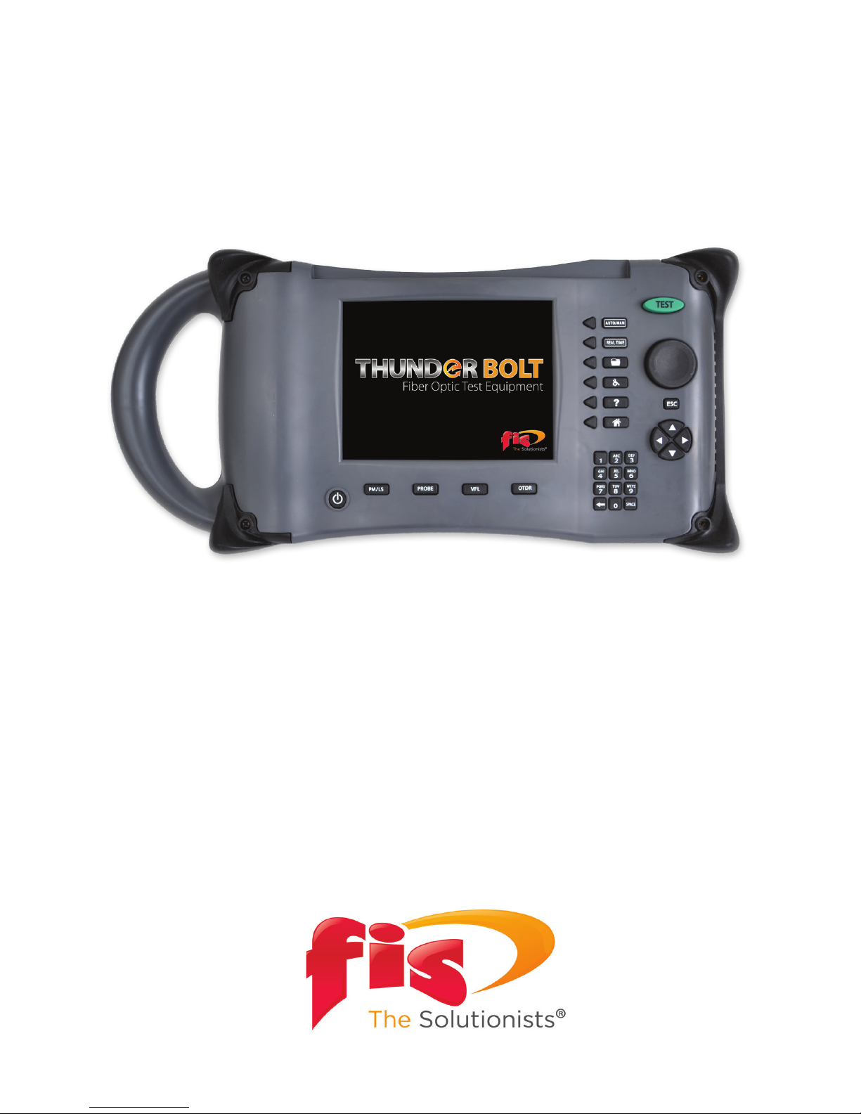
Thunder Bolt Multi-Tester
Operations Manual
Page 2

Page 3

TABLE OF CONTENTS
Thunder Bolt Multi-Tester Universal Features and Settings ..................... 1
Thunder Bolt Application Operation ............................................................ 2
Trace View Pane .......................................................................................... 2
Cursor Marker Pane .................................................................................... 3
Scan Settings Pane ..................................................................................... 3
Soft Key Options .......................................................................................... 3
Hard Key Options ........................................................................................ 6
Event Table Screen ...................................................................................... 7
Event Table Pane ......................................................................................... 8
Event Detail Window ................................................................................. 8
Soft Key Options .................................................................................. 8
File Manager Screen .................................................................................. 9
Soft Key Options .................................................................................. 9
Moving and Copying Files ........................................................................ 10
Thunder Bolt Multi-Tester Quick Start ........................................................... 11
Multi-Tester Quick Start ............................................................................. 11
OTDR Standard Operation ....................................................................... 11
Extended Dynamic Range ........................................................................ 12
Saving or Opening a File ........................................................................... 12
Inserting/Editing/Removing an Event ................................................... 13
Macrobend Detection ................................................................................ 14
Thunder Bolt Multi-Tester Project Mode Operation ................................... 15
Thunder Bolt Multi-Tester Gigabit Analyzer Option .................................. 17
Thunder Bolt Multi-Tester Line Checker ........................................................ 17
Page 4

Main Menu
The rst screen you see when the Thunder
Bolt has booted up, contains an array of
icons. One icon for each application or
section of the Thunder Bolt. Highlight any
of the icons using either the scroll wheel
or the directional arrows and then press
the center of the scroll wheel to launch
the application.
Time / Date
A time and date stamp is recorded every
time a scan or test is performed and
saved. To change the Time or Date go to
the System Setting tab in the Systems
Setting application. Use the numerical
keypad to insert correct time.
Screen Brightness
The screen brightness is user adjustable.
To adjust the brightness go to the System
Setting tab in the Systems Setting
application.
Help Feature
The Thunder Bolt has an on-board help
application which is activated by pressing
the Help button on the front panel.
Distance Units
Select this feature to change the unit of
measurement (Kilometers, Meters, Feet,
Kilo-Feet, Miles) for the Thunder Bolt.
Launch Box
Enter the distance of your launch reel
into this feature. The OTDR will omit
measuring this distance in the result/
event table.
1
Thunder Bolt Multi-Tester
Universal Features and Settings
Fiber Instrument Sales, Inc. | 1.800.5000.FIS(347) | www.berinstrumentsales.com
Page 5
2
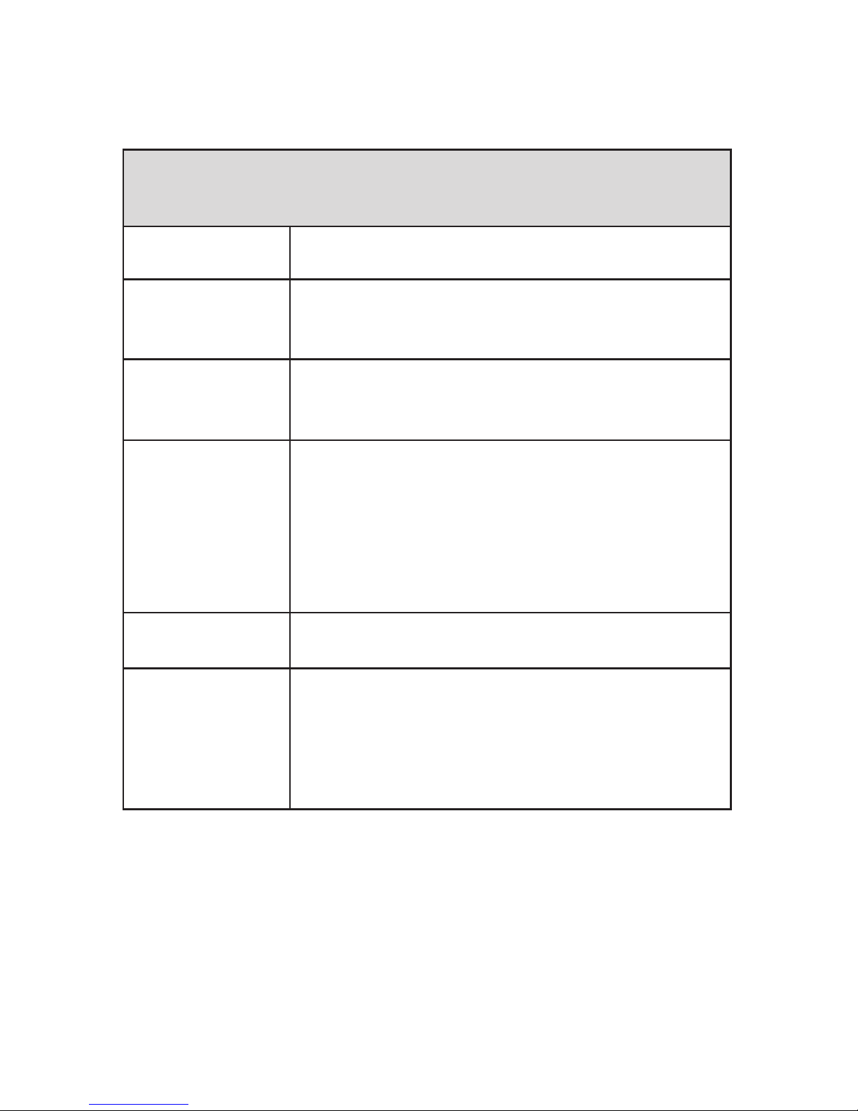
Trace View Pane
Reected Power
(Y-Axis)
Does not modify
Range / Distance
(X-Axis)
Can be either automatically set by the OTDR
or manually set by the user (see Soft Key
options; Pulse Width & Range).
Trace
Zoom scale and View can be set by user
(see Zoom and View in Soft Key Options
section).
Cursors
The Thunder Bolt has an A and B cursor. The
active cursor appears in “red” and will have
cursor location and loss readings shown
above it. The inactive cursor is shown in
“blue”. To switch between cursors press the
center of the scroll wheel. To move the active
cursor, turn the scroll wheel left or right.
Event Markers
Each event is identied by a number. Each
marker corresponds to an Event Table event.
Zoom
You can expand the trace either horizontally
or vertically in order to zoom in on a
particular section of the trace. The left /
right arrows zoom or expand the trace
horizontally. The up / down arrows expand
the trace vertically.
Thunder Bolt Multi-Tester
Application Operation
Fiber Instrument Sales, Inc. | 1.800.5000.FIS(347) | www.berinstrumentsales.com
Page 6
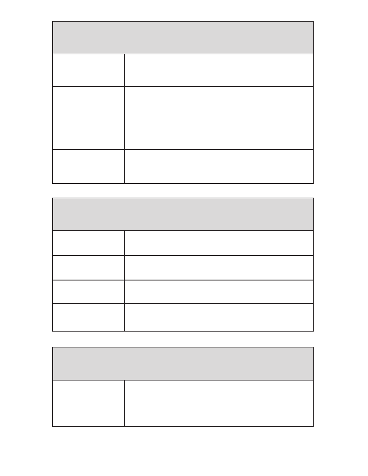
Cursor Marker Pane
Cursor Location
Each cursor has a distance from the
origin value next to it. The active cursor is
highlighted
A - B
Distance between cursor A and cursor B
along the trace line.
Loss Reading
This line shows the cursor based loss
readings. The user can choose between
2-Point or 4-Point loss methods.
Avg. Loss
This reading shows the average dB per
Kilometer Loss (dB/Km) of the ber between
the two cursors.
Scan Settings Pane
λ
The wavelength the current trace was
scanned at (ex. 1550nm)
П
The pulse width the current trace was
scanned at (ex. 50ns)
Ӂ
The range the current trace was scanned at
(ex. 10Km)
€
The scan duration of the current trace was
scanned at (ex. 10 sec)
Soft Key Options
Wavelength
Press this soft key to call up a menu of
available Wavelengths. Use the scroll wheel
or the up / down arrows to highlight the
wavelength you would like to use.
3
Fiber Instrument Sales, Inc. | 1.800.5000.FIS(347) | www.berinstrumentsales.com
Page 7

Distance Units
Select this feature to change the unit of
measurement (Kilometers, Meters, Feet,
Kilo-Feet, Miles) for the Thunder Bolt.
Pulse Width & Range
Press this soft key to call up a menu
of available Pulse Widths & Ranges.
Use the scroll wheel and arrows to
highlight the desired Pulse Width, then
press the right arrow to switch to the
Range menu. Use the scroll wheel and
arrows to highlight the desired Range.
Press the Accept soft key to enter your
selections.
Duration
Press this soft key to call up a menu
of available scan Durations. Use the
scroll wheel or the up / down arrows to
highlight the duration you would like
to use.
View From
Press this soft key to toggle through
the View From options.
• Origin - Displays standard trace with
the origin on the far left side
• Cursor A - Displays the trace with
Cursor A xed in the center of the
display. The trace will scroll when
you move Cursor A.
• Cursor B - Displays the trace with
Cursor B xed in the center of the
display. The trace will scroll when
you move Cursor B.
Show/Hide
Event Table
Toggle this soft key to call up the Event
Table screen or hide it and bring up
the A-B loss screen where you can use
the cursors freely to manually measure
sections of ber. Cursors will only scroll
to the recorded events when event
table is displayed.
4
Fiber Instrument Sales, Inc. | 1.800.5000.FIS(347) | www.berinstrumentsales.com
Page 8

More
Press this key to see more soft key
options.
Macrobend Test
Press this key to start the Macrobend
Test and the OTDR will scan two
wavelengths right after each other and
overlay them when done. The user can
then select the threshold of detection.
Header
Press this soft key to go to the Header
information entry screen.
Loss Method
Press this soft key to toggle through
the Loss Method options.
• 2-Point - Measures the loss
between cursor A and B
• 4-Point (LSA) - Uses Least
Squares Approximation method
to determine loss. This procedure
uses both main cursors and two
minor cursors to determine the
averaging areas used to determine
the loss. The distance between
the cursors can be manually
set. The cursor distance can be
locked so the averaging area size
remains the same as you adjust the
position relative to the event.
Lock Main Cursor
Press this soft key to toggle between
Lock and Unlock the distance between
Cursor A and B.
Lock Range Cursor
This function only works when you
are in 4-point loss mode. It locks the
distance between the major and minor
cursors.
5
Fiber Instrument Sales, Inc. | 1.800.5000.FIS(347) | www.berinstrumentsales.com
Page 9
Save
Press this soft key to have the OTDR
save your current trace using a le
name the user creates. The trace will
be saved in the current active save
location.
Save As
Press this soft key to have the OTDR
save your current trace using a le
name the user creates. The user will be
asked to specify a save location.
Open
Press this soft key to open the le
explorer window that has all of the
save locations on the OTDR. To open
a saved le use either the scroll wheel
or the directional arrows to highlight
the folder you want to open. Press the
Right Arrow to open and show the
contents of the folder. Once you have
found your le, Press the Open soft key
or the center of the scroll wheel to
open the trace.
6
Fiber Instrument Sales, Inc. | 1.800.5000.FIS(347) | www.berinstrumentsales.com
Hard Key Options
Test
Use this button to activate or start scans on
the Thunder Bolt.
Auto/Man
This button toggles between auto setting
and manual setting in the OTDR function.
When in Auto mode the OTDR will set the
pulse width and range settings automatically.
In Manual mode wavelength, pulse width,
range and duration are set by the user.
Real Time
This button activates the real time scan
feature in the OTDR application. The user
selects all of the scan parameters manually.
When a real time scan is in process,
pressing this button will stop the scan.
Page 10

File Manager
This button opens the le management
section of the OTDR. You may save,
recall, copy and transfer les from this
section. (see File Manager section for
details of each function)
System Settings
This button opens the System Setting
section of the OTDR. (see System
Setting section for details)
Help
This button opens the Help section.
Depending on where you are in the
Thunder Bolt system will determine the
initial help topics that will be displayed.
You may also search the help les
manually.
Home
This button takes you back to the main
menu screen where you may select an
OTDR application to open.
Distance
The overall distance to the end event on the
trace.
Loss
The overall loss value for the entire OTDR
trace.
ORL
The optical return loss value for the entire
OTDR trace
7
Fiber Instrument Sales, Inc. | 1.800.5000.FIS(347) | www.berinstrumentsales.com
Event Table Screen
End to End Link Info Pane
Page 11

8
Fiber Instrument Sales, Inc. | 1.800.5000.FIS(347) | www.berinstrumentsales.com
Event Type
Indicator
€ Reective Event
Ӂ Non-reective Event
П End Fiber Event
¥ Ghost Event
Location
Distance of the event from the OTDR or the
end of the launch cable.
Loss
The optical loss of the event measured in
dB. All readings above the pass/fail threshold
are highlighted in red.
Ref.
The optical reectance of the event
measured in dB. All readings above the pass/
fail threshold are highlighted in red.
Cumm. Loss
The cumulative loss of the trace to this
point.
Span
The distance between the current event
and the previous event.
Soft Key Options
Trace
Press this soft key to return to the full trace
view.
Event Table Pane
Each row on the event table represents an event on the trace detected
by the OTDR. The row numbers correspond to the event identication
numbers seen on the trace. Each event has the following information:
Event Detail Window
In this window a close up trace view of the highlighted event is shown
with a description of the event written underneath.
Page 12
9
Fiber Instrument Sales, Inc. | 1.800.5000.FIS(347) | www.berinstrumentsales.com
Insert
Press this soft key to insert an event into
the event table.
Remove
Press this soft key to remove an event from
the event table.
Edit
Press this soft key to edit the classication
of the event.
Clear Selection
Press this soft key to clear (un-select) all
selected items.
Soft Key Options
New Folder
Press this soft key to create a new folder in
the Thunder Bolt’s le. A Text Input window
will appear for creating the folder name.
Press the “Accept” soft key to enter the
folder name and close the text window.
Select Press this soft key to highlight a le.
Move
Press this soft key to move a le or folder to
a new location. * See below.
Copy
Press this soft key to copy a le or folder to
a new location. * See below.
Rename
Press this soft key to Rename a le or
folder. A Text Input window will appear
for creating the new le or folder name.
Press the “Accept” soft key to enter the new
name and close the text window.
File Manager Screen
Use either the scroll wheel or the directional arrows to navigate
through the le system. To open a folder, highlight it and then press the
right direction arrow.
Press the “more” soft key to go to the next page.
Page 13

10
Fiber Instrument Sales, Inc. | 1.800.5000.FIS(347) | www.berinstrumentsales.com
* Moving and Copying les:
Moving - If you would like to move a le from one location to another,
select the le (by choosing “Select” in the soft key menu, it will
highlight the le), then select “Move” in the soft key menu. Now scroll
and nd the location you wish to move the le to and then select
“Move to Here” in the soft key menu. The le now should no longer be
at its original location and in the new location you have selected for it.
(this is similar to a cut & paste process on a PC).
Copying - This is similar to the moving process but the le will be
copied to the new location and still remain in the original location.
Page 14

11
Fiber Instrument Sales, Inc. | 1.800.5000.FIS(347) | www.berinstrumentsales.com
Thunder Bolt Multi-Tester Quick Start
Multi-Tester Quick Start
1. Press the Power button [ ] to turn on the OTDR unit.
2. Highlight the OTDR app icon and Press the center of the
Scroll Wheel to select.
3. Clean OTDR port with Isopropyl Alcohol and a mini foam swab
before inserting a connector.
4. Clean both connector ends of your launch cable.
5. Attach one end to the appropriate port on the OTDR.
6. Connect the ber under test to the launch cable.
7. Select the desired wavelength using the soft-keys on the
right-hand side of the screen.
8. Press the TEST button to initiate the Auto Test function.
- The Auto Test function will automatically select the
range, pulse width and duration for the scan.
OTDR Standard Operation
1. Highlight and select the OTDR app icon on the main menu
screen.
2. Clean the OTDR port as well as the connector ends of your
launch cable.
3. To manually set your parameters, use the soft keys on the right
side of the screen, select the desired wavelength, pulse width,
range, and duration. (To have parameters automatically set,
select the hard key AUTO/MAN so it displays “Automatic”
under pulse width & range (duration will still need to be set
manually)
4. If you are using a launch cable and wish to omit it on your
Page 15

12
Fiber Instrument Sales, Inc. | 1.800.5000.FIS(347) | www.berinstrumentsales.com
Saving or Opening a File
1. To save a new trace once completed, select the soft key “More”
until options for saving appear on the soft key menu.
2. Then select “Save As” which will bring you to the File Manager
screen.
3. Select the folder you wish your le to be saved in by using
the arrow keys (Up/down scrolls to dierent folders, left/right
opens or closes the highlighted le folder).
4. Select “Save” and a text box will appear for you to name the le.
5. If you need to create a new folder select “New Folder” with the
soft key command. A text box will appear for you to name it.
6. To open a le, make sure you are in the OTDR application, nd
and select the soft key option for “Open”.
7. Use the arrow keys to locate/highlight the le you wish to open.
8. Then select the soft key “Open”.
ber under test, push the “Settings” hard key (wrench & gear
symbol) and scroll down to the “Launch Box” and enter the
distance of the launch cable. The OTDR will omit this section of
cable after the test and won’t include it in the nal link results.
5. Once this is complete push the OTDR hard key at the bottom of
the screen to get back to the OTDR graph and begin your scan
by pressing the green TEST button.
6. Once the scan has completed, you can view or hide the event
table by toggling the corresponding soft key.
7. Use the rotary wheel to scroll through the dierent events on
the trace. If you wish to use the A & B cursors press the soft key
“Hide Event Table”. You will now have free range to move the
cursors, just depress the rotary wheel to toggle between A & B.
(Whichever cursor is colored in red is the one you can control)
Page 16

13
Fiber Instrument Sales, Inc. | 1.800.5000.FIS(347) | www.berinstrumentsales.com
9. If you modify the opened le in any way, you will have the
option to “Save” your changes. Either, select save from the soft
key menu or before you can close the le the unit will ask you if
you want to save changes.
• Please note: If changes are made to an existing le an asterisk
(*) will appear next to the displayed le name in the upper left
hand corner of the OTDR screen. Once you select “save” the
asterisk will go away as the changes have been saved.
Inserting/Editing/Removing an Event
When viewing a trace, make sure you have the event table
displayed, select soft key “More” until you come to the soft key
menu that includes: Header, Insert Event, Remove Event, Edit
Event.
Insert: Select INSERT EVENT from soft key menu, choose
placement type, then choose reective or non-reective…
• Non-Reective: use the dial to place the A cursor just before
the event. Once you push the dial button, the A cursor will
be set and now you control the B cursor, place that at the
end of the section you want to measure the event with. The
unit should display the location of cursor A (start of event) as
well as the measured loss between the two cursors. Select
“Accept” and the event will populate in the event table.
• Reective: Use the dial to position the A and B cursors the
same way you would to measure a non-reective event.
However after this is completed, you must select the soft
key option “Measurement” until reectance is displayed,
another B cursor will appear, use the dial to move it until
you reach the highest point of the reective “spike”(use the
arrow keys to zoom in and out if needed). You will notice this
value change in the top left corner as you move the B cursor
around. When you get it to the proper place, select “Accept”.
Edit: While having the event table displayed, use the dial to scroll
to the particular event you would like to edit. Then select “EDIT
EVENT” from the soft key menu. (Use the arrow keys to zoom in
or out if needed). Use the A & B cursors to re-measure an event
Page 17

14
Fiber Instrument Sales, Inc. | 1.800.5000.FIS(347) | www.berinstrumentsales.com
as needed. When the cursors are placed in a satisfactory location,
press “ACCEPT”. The edited event information will populate in the
event table.
Remove: While having the event table displayed use the dial
to scroll to the particular event you want to remove, and select
“REMOVE EVENT” from the soft key menu. The event will
disappear from the event table and the events on the table will be
automatically re-numbered.
Macrobend Detection
1. Open the OTDR application and select the “MORE” soft key to
go to the next soft key menu.
2. Select “MACROBEND TEST” once you have the cable under test
plugged in.
3. The unit will run an OTDR scan at the two wave lengths
(850/1300 for Multimode, or 1310/1550 for singlemode). The
scan will run at the parameters and averaging time that the
user has selected on the previous soft key menu.
4. Once both scans are done, select the Macrobend threshold that
you wish to use and the traces will be displayed with the ability
to toggle between 1310, 1550 with the corresponding event
tables.
Page 18

15
Fiber Instrument Sales, Inc. | 1.800.5000.FIS(347) | www.berinstrumentsales.com
Thunder Bolt Multi-Tester
Project Mode Operation
Project Mode allows the user to test many bers in an easy and
quick fashion. The user just needs to set up a le saving matrix, the
parameters and the amount of cables/bers they have to test. Once
that is set up, just press test for each scan and it will auto-save or ask for
you to verify before saving.
1. Open “Project Mode” application.
2. Select the soft key that represents “New Project”, choose a le
path for your project and name it.
3. Now, use the dial to highlight and select the “Folder” box, this
will be the folder path the individual trace les will be located
in once the project is complete.
4. Then select the “File” box. This will allow you to name the les
that will be included in the project, as well as select unique le
paths (trace info) that will distinguish each trace from the other
such as wavelength, ber number, and/or cable number all the
while being under the same base le name.
A. For example, after you give a base name to the le (ABC),
before you select “Accept”, select the “Insert Trace Info” soft
key. You will then see a variety of trace information labels.
If you select <Wavelength> 1310nm or 1550nm traces
will be noted in the le name. If you are, for example,
testing a number of bers and you select <Fiber ID> it will
automatically save and organize your les by wavelength
and the number of each ber (1,2,3….).
B. Also, if you are testing multiple cables, you can select
<Cable ID> it will dierentiate the wavelengths as well
as the traces contained in cable 1 vs. cable 2 (or however
many cables you are testing). Select how many bers and
how many dierent cables you are planning on testing
and the unit will automatically populate and organize the
le names.
Page 19

16
Fiber Instrument Sales, Inc. | 1.800.5000.FIS(347) | www.berinstrumentsales.com
Please note: When selecting dierent trace information to be
included in your le name, it’s recommended that you insert a dash
(-) in between each selection, if you don’t, all letters & numbers will
be muddled together. Without the dash the le name will appear
as abc1550nm11 vs. with a dash put in: abc-1550nm-1-1.
5. Next, name the “To” and “From” locations as well as the number
of bers and cables you will be testing. This is important
because it will allow the OTDR to auto-populate the le names
when it will be saving after each scan.
Example: ABC{base le name}-1310nm{wavelength}-1
{cable ID} -3 {ber ID}
6. Next, use the soft key “Add Scan” to add however many scans
you wish to be shot on each ber.
7. Once you have the satisfactory number of scans set up, now
you can either customize your parameters for each one or you
can mark the “x” under “AUTO” and it will automatically set
parameters for you.
8. If you wish to set them manually, you can unmark the “x” for
AUTO and then use the dial to select the particular parameter
and use the dial or arrow keys to scroll through the various
parameter options to select for pulse width, range, and
duration.
9. Before you start your rst scan, select the “x” under “Conrm” if
you want the unit to ask you if you want to save or discard the
last scan. If you choose discard, the unit will then reshoot the
last scan again. If the trace seems satisfactory to you, select
“Save” and the unit will save the le according to the saving
matrix you had set up earlier and automatically start scanning
in the next wavelength on the same ber.
A. If you choose to leave “Conrm” unmarked, the OTDR
will automatically save the completed scan and move
on to the next scan without you being able to conrm or
evaluate it.
10. Once all scans on a single ber are complete, the unit will wait
for you to switch to the next ber. Once you do, push the green
TEST button to start the scan(s) on the next ber.
Page 20

17
Fiber Instrument Sales, Inc. | 1.800.5000.FIS(347) | www.berinstrumentsales.com
11. Once the scans of all bers are completed you can go back and
view any scan you wish. When on the main graph screen, select
the soft key for “Jump to Scan” and a small box will appear and
you will select the scan#, ber#, and cable# of each to view after
selecting “Accept”.
12. If you wish to view them in the OTDR application, select “Open”
in the soft key menu and select the folder that was selected
when you originally created in the project mode.
Thunder Bolt Multi-Tester Gigabit
Analyzer Option
Thunder Bolt Multi-Tester
Line Checker
1. Highlight the Gigabit Analyzer application icon on the main
menu.
2. Using the soft arrow key, select the ber type that will be
tested.
3. Select the type of test you wish to conduct (1 Gig or 10 Gig).
4. Within 5 seconds, the results are displayed (Distance,
Attenuation, Reection).
5. Record pass/fail results.
NOTE: This application is not an Ethernet tester, it does not
send packets of data through the ber, rather it evaluates the
selected cable and compares the results to the manufacturer’s
specications to determine if PHYSICALLY the cable can handle a 1
or 10 gig signal.
1. Clean and connect your ber under test and plug into the OTDR
port.
2. Use the soft keys to select, ber type and launch distance if
applicable. It will only run in 1550nm.
3. Push “TEST”, record results.
Page 21

Notes:
Page 22

Notes:
Page 23

Notes:
Page 24

161 Clear Road
Oriskany, NY 13424
Ph: 315.736.2206 Toll Free: 1.800.5000.FIS(347) Fax: 315.736.2285
www.berinstrumentsales.com email: info@berinstrumentsales.com
 Loading...