

Page 1

T9.1
OWNERS MANUAL
™
Page 2

TABLE OF CONTENTS WARNINGS
Warnings ....................................................................................................................................................................................................3
Quick Start Guide ......................................................................................................................................................................................4
T9.1 Diagram ..............................................................................................................................................................................................5
T9.1 Magazine Diagram ...........................................................................................................................................................................6
Operational Instructions ..........................................................................................................................................................................8
Loading Magazine.....................................................................................................................................................................................9
Loading First Strike Rounds...................................................................................................................................................................10
Airing up via Magazine .........................................................................................................................................................................11
Setting Velocity .......................................................................................................................................................................................12
Hopper Attachment ................................................................................................................................................................................13
Stock Adapter Instructions ..................................................................................................................................................................14
Solid CO2 Stem and sight Instructions ................................................................................................................................................15
Cleaning & Maintenance ......................................................................................................................................................................16
Warranty and Repairs ...........................................................................................................................................................................17
T9.1 Assembly Diagram..........................................................................................................................................................................18
Gun Body assembly ................................................................................................................................................................................19
Engine & Firing Bolt Assembly..............................................................................................................................................................20
Trigger Group Assembly ........................................................................................................................................................................21
Regulator Assembly................................................................................................................................................................................22
Magazine Assembly ...............................................................................................................................................................................23
Co2 Valve Housing Assembly ................................................................................................................................................................24
WARNING/LIABILITY STATEMENT
This marker is not a toy and is surrendered by UTS, with the understanding that the purchaser assumes all liability from
unsafe handling or any action that constitutes a violation of any applicable laws or regulations. UTS, shall not be liable
for personal injury, loss of property or life resulting from the use of this product under any circumstances, including any
intentional, reckless, negligent or accidental discharges.
All information contained in this manual is subject to change without notice. UTS, reserves the right to make changes
and improvements to products without incurring any obligation to incorporate such improvements in products
previously sold.
If you, as a user, do not accept liability, UTS, requests that you do not use a UTS marker. By using this UTS marker you
release UTS, of any and all liability associated with its use.
WARNING:
- Careless use or misuse may result in serious bodily injury or death!
- Eye protection designed for paintball must be worn by the user and all persons within range.
- Must be 18 years of age or older to operate or handle any paintball gun and paintball gun accessories without adult or
parental supervision.
- Read and understand all cautions, warnings, and operating manuals before using any paintball gun or paintball gun accessory.
- Do not aim paintball gun at eyes or head of people or at animals.
- Paintball guns are to be used with paintballs only.
- To prevent fire or shock hazard, do not expose unit to rain or moisture.
- To prevent fire or shock hazard, do not immerse unit in liquids.
- To prevent fire or shock hazard, do not disassemble any electronic paintball device.
- The disposal of the battery if used to power this product may be regulated in your area.
- Please conform to all local or state regulations with regard to battery disposal.
- Use common sense and have fun.
Any tampering with the unit voids your warranty. There are no consumer serviceable parts inside this unit. The use of non factory
authorized components within this product may cause a fire or shock hazard.
IN NO EVENT SHALL SELLER BE LIABLE FOR ANY DIRECT, INCIDENTAL OR CONSEQUENTIAL DAMAGES OF ANY NATURE, OR
LOSSES OR EXPENSES RESULTING FROM ANY DEFFECIVE PRODUCT OR THE USE OF ANY PRODUCT.
WARNING: This product may contain chemicals known to the state of California to cause cancer and/or defects or other
reproductive harm. Wash hands afer handling.
You must be at least 18 years of age to purchase this product. This product may be mistaken for a firearm by law enforcement
officers or others. Altering the color of the product or brandishing the product in public may be dangerous and may be
considered a crime.
PAINTBALL GUNS AND PAINTBALL GUN
ACCESSORIES ARE NOT TOYS!
Troubleshooting .......................................................................................................................................................................................25
Warranty Registration Card ..................................................................................................................................................................27
™
2 | T9.1
3
Page 3
QUICK START GUIDE
Thank you for purchasing the First Strike T9.1 paintball marker. Like any paintball marker, it is important
that safety is on the forefront of your mind at all times when using this product. Never operate the T9.1
without ASTM compliant goggles or aim at anyone that is not wearing proper goggles intended for the
game of Paintball. The First Strike T9.1 is an advanced system that is suitable for all levels of play and will
provide years of service if the following steps are meticulously followed.
1. Before airing up, place 3 drops of First Strike approved oil at the top of the CO2 Air Cavity.
2. Insert the barrel into the front of the T9.1, and twist into locked position by inserting your finger
into the barrel and twisting.
3. Insert 12gram CO2 cartridge into Magazine by placing in CO2 Cavity.
4. Engage the air source by twisting flip-knob base screw.
5. Insert magazine into grip firmly
6. Dry fire 3-4 times to distribute oil evenly through the marker.
7. Also chrono your T9.1 prior to use.
CATCH TECH TIPS AND INFO ON:
DON’T FORGET TO REGISTER!
Register your T9.1 at www.first-strike.com
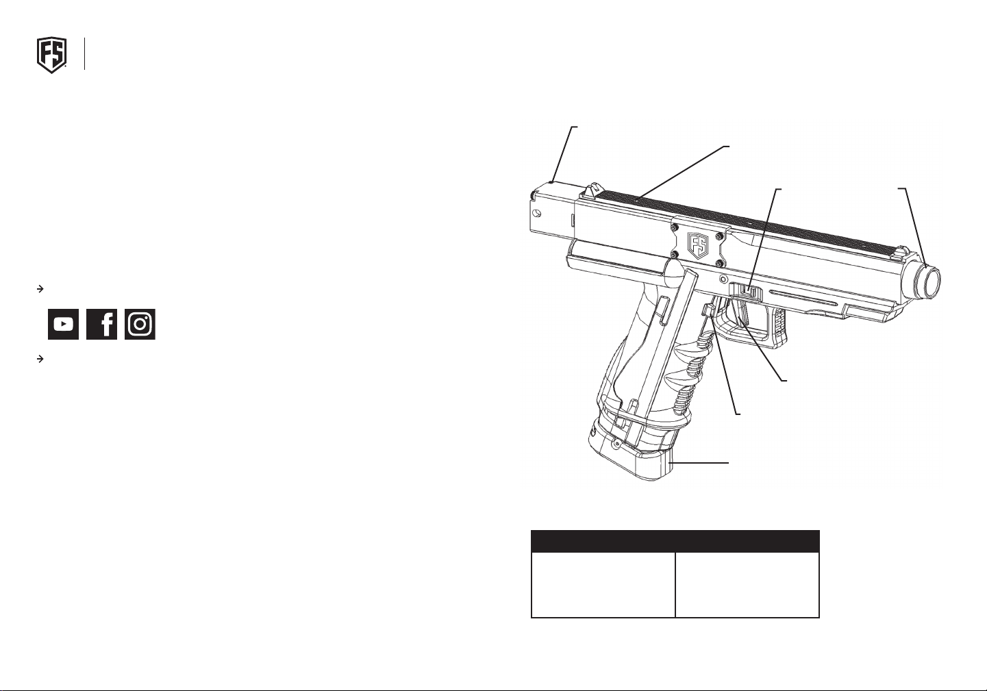
T9.1 DIAGRAM
STOCK ADAPTER
PROJECTILE VIEWPORT
SAFETY
TRIGGER
MAGAZINE RELEASE
BUTTON
BARREL
4 | T9.1
MAGAZINE
MODEL SPECIFICATIONS
CALIBER
ACTION
POWER
LENGTH
™
.68
SEMI-AUTO
CO
2
11”
HEIGHT
BARREL LENGTH
WEIGHT
MAGAZINE
8”
6.5”
2.7 LBS
8 ROUNDS
5
Page 4
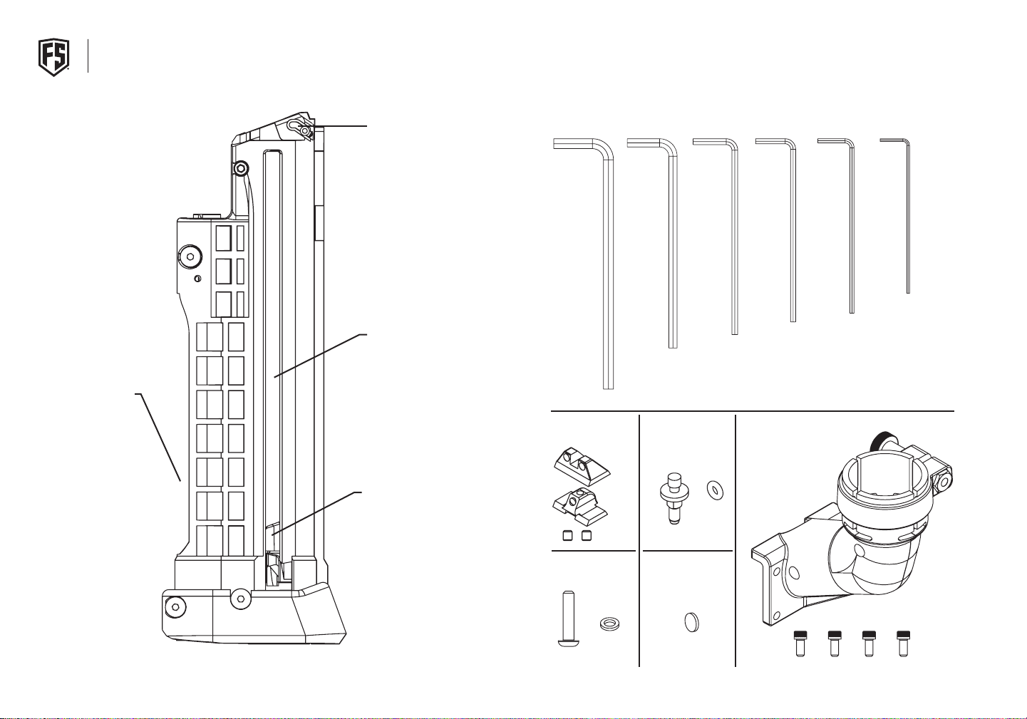
T9.1 MAGAZINE DIAGRAM UNIVERSAL PACK INVENTORY LIST
ALLEN WRENCHES
3/16” 7/64” 3/32” 5/64” .050”4mm
CO2 CAVITY
PROJECTILE
RETAINER PIN
PROJECTILE FOLLOWER
TRACK
6 | T9.1
FRONT & REAR SIGHT
PROJECTILE FOLLOWER
FRONT HANDLE
SCREW & WASHER
™
SOLID CO2 STEM
WITH O-RING
REG BODY PLUG
HOPPER ELBOW AND
HOPPER SCREWS
7
Page 5
OPERATIONAL INSTRUCTIONSOPERATIONAL INSTRUCTIONS
GETTING STARTED
Read this entire manual before using this marker. Keep your
marker pointed in a safe direction at all times.
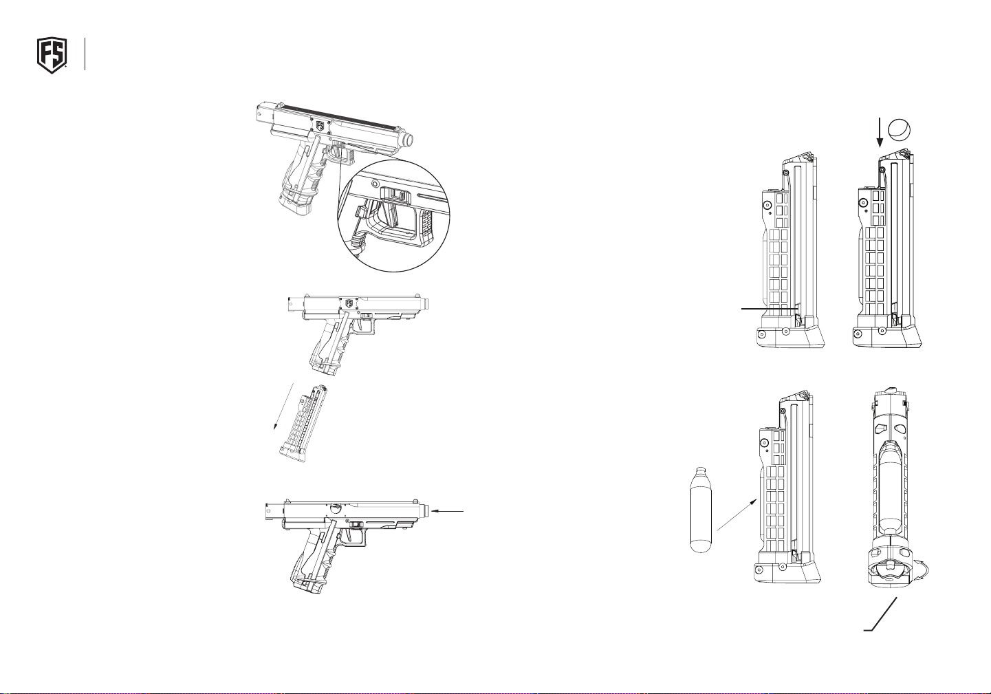
1. SAFETY - Place the T9.1 in safe position by moving safety
so no red is visible. The safety is ambidextrous and can be
operated from either side of the T9.1.
* Visible red indicates that launcher can discharge.
2. UNLOADING MAGAZINE - Ensure that there are no
projectiles in your marker by placing your hand under the
magazine, pressing the magazine release, and pulling the
magazine free from the T9.1.
3. REMOVING THE BARREL - Ensure that there are no
projectiles remaining in the marker by removing the
magazine and looking through the grip into the breach.
Then you can remove the barrel by pressing on the end
of the barrel and rotating it counterclockwise. Note the
channel in the barrel and the barrel lock in the receiver as
it slides free. To reattach the barrel, line up the channel
with the barrel lock, slide the barrel back in the receiver,
push on the end of the barrel, and turn clockwise until
the barrel locks into place. Pull on the end of the barrel to
ensure it is properly seated.
4. LOAD PROJECTILES - Place 8 projectiles into the
magazine from the top. The projectiles will be held in place
automatically by the projectile retainer pin. You can also
lock the ball pusher in the down position by pulling down
on the ball pusher ears and locking them at the bottom of
the ball pusher track.
NOTE: FOR INSTRUCTIONS ON FIRST STRIKE ROUNDS,
PLEASE REFERENCE PAGE 10.
FOLLOWER
EARS
5. LOADING C02 CARTRIDGE - Obtain a 12 gram CO2 cartridge.
Insert the CO2 cartridge into the CO2 slot of the magazine
with the small end of the CO2 cartridge pointing up and
into the puncture pin of the magazine. Next, rotate the
flip knob base screw clockwise quickly until the cartridge
has sealed.
LOAD PROJECTILE
8 | T9.1
FLIP KNOB
BASE SCREW
™
9
Page 6
OPERATIONAL INSTRUCTIONS OPERATIONAL INSTRUCTIONS
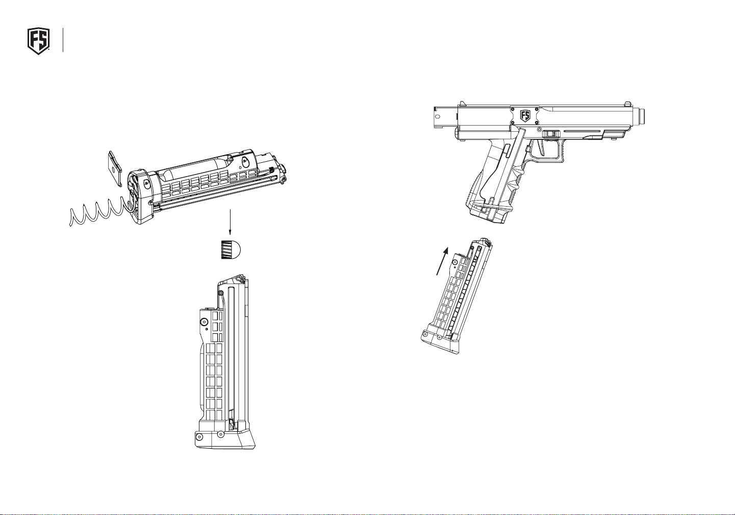
RED SPRING/SILVER SPRING
When using First Strike™ projectiles, make sure the red
magazine spring is installed. The silver spring is designed
for use with traditional .68 caliber paintballs. While the red
spring can be used with traditional .68 caliber paintballs, its
higher tension increases the risk of the paintballs deforming
over time.
LOADING FIRST STRIKE
Always load First Strike projectiles so rounded nose exits
barrel first. Always chronograph with First Strike before use
to ensure velocity is below 300 fps.
8. LOAD MAGAZINE - Place the magazine in the grip of the T9.1
marker with the projectiles closest to the end of the barrel.
Once the mag has started into the grip seat, it completely until
has been secured by the magazine release.
NOTE: If magazine does not lock on first insertion, remove
it completely and reinsert.
10 | T9.1
™
11
Page 7
OPERATIONAL INSTRUCTIONS HOPPER ATTACHMENT
FIRING THE T9.1
1. If the CO2 cartridge has been punctured by the puncture pin and the magazine has
been inserted into the gun, then the T9.1 is now ready to fire. Point the T9.1 in a safe
direction, rotate the safety so red is visible, and pull the trigger.
NOTE: Extra magazines can be carried for quick reloads in the field.
UNLOADING THE T9.1
1. Place T9.1 in the safe mode and point in a safe direction. If all projectiles have been
fired, place hand under magazine and press magazine release with other hand.
Catch magazine so it does not fall on ground. Visually inspect the magazine well to
ensure all projectiles are clear from the T9.1. Visually inspect the projectile view port
to ensure all projectiles are clear.
2. If all projectiles have not been fired, follow above procedures but ensure that
you turn the T9.1 on its side while removing the magazine. The projectile that is in
the chamber will be free and can fall on the ground if the T9.1 is kept in a vertical
position. Place your hand under the magazine well and capture the loose projectile
as you turn the T9.1 vertically.
3. Pull back on the projectile retainer pin to remove the projectiles from the magazine
and turn the flip knob base screw counterclockwise to free the CO2 cartridge from
the magazine.
4. Your T9.1 should now be free of any projectiles. Verify the T9.1 is on safe and store in
a safe and secure location.
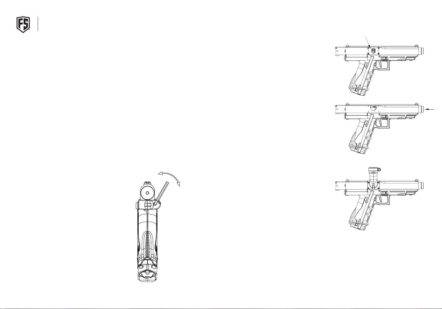
SET VELOCITY
1. Insert provided 3/16” Allen wrench as depicted.
2. To increase velocity, tum clockwise. To decrease velocity
turn counter-clockwise.
3. Fire once to clear chamber after each adjustment, then
measure velocity of the second shot.
SAFETY TIP: Always measure marker’s velocity before playing
paintball. Never shoot at velocities in excess of 300 ft/s (91 .44
mls). Recommended velocity is 270 ft/s.
1. REMOVE HOPPER COVER PLATE - Remove the Hopper
Cover Plate by removing the four (4) Cover Plate Screws
(H-B 440 3/16) by using a 1/16 Allen Wrench.
2. ROTATE BARREL - With the magazine removed, push in on
the barrel and rotate clockwise until it locks in the hopper
position, so that you can see the breach through the
hopper window.
3. ATTACH HOPPER ELBOW - Attach the Hopper Elbow
located in the universal pack that came with the rifle using
the four (4) Hopper Screws, also located in the universal
pack. These screws require a 3/32 Allen Wrench.
12 | T9.1
™
13
Page 8
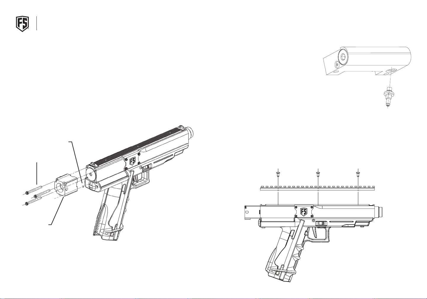
REMOVING & RE-INSTALLING STOCK ADAPTER SOLID CO2 STEM & SIGHT INSTALLATION
1. Before removing the stock adapter remove all air sources. Point the marker in a
safe direction and fire until all air has left the marker.
2. Using the 7/74” Allen Wrench from your Universal Pack, remove the three (3)
Stock Adapter Screws.
3. Be sure not to lose the Rear Body O-Ring or there will be nothing to hold it in
place once the stock adapter has been removed.
4. To operate the T9.1 without the Stock Adapter in place, you must replace the
forward most regulator body O-Ring with a 006 Reg Body Plug. (See page 22)
5. To re-install the Stock Adapter, first position the Rear Body O-Ring onto the lower
right corner of the marker body and press the Stock Adapter onto it. Then reinstall the three (3) Stock Adapter Screws. (Snug all 3 screws before tightening)
6. To begin using the stock adapter again, remove the Reg Body Plug from the
regulator and re-install the 006-B90 Reg Body O-Ring.
REAR BODY O-RING
STOCK ADAPTER SCREWS
STOCK ADAPTER
NOTE: This stock adapter allows
you to connect a remote line directly
to the bottom of the adapter or thread
a tank directly into the back of the
stock adapter.
SOLID CO2 STEM INSTALLATION
1. To replace the CO2 Stem with the Solid CO2 Stem, first
remove the grip frame from the gun body assembly. (See
page 18)
2. The CO2 Stem can be removed with a 4mm wrench or a
small adjustable wrench. Be sure that O-Ring is on the Solid
CO2 Stem. DO NOT OVER TIGHTEN onto the Reg.
SIGHT INSTALLATION
1. To install the sights that came with you universal pack, first remove the Top Tac
Rail. To do this remove the three (3) Tac Rail Screws with 3/32” Allen Wrench.
2. To install the sights, slide the sights into the dovetails on the top of the gun body
and secure using the set screws with a .050 Allen Wrench that came with the
universal pack.
14 | T9.1
™
15
Page 9

T9.1 CLEANING & MAINTENANCE
WARRANTY & REPAIRS
CLEANING
• Never perform maintenance on a loaded or pressurized T9.1 marker.
• Remove all projectiles and CO2 cartridges from the magazine and marker prior to doing any
cleaning or maintenance.
• Never use petroleum based cleaning solvents or lubricants.
• Do not use cleaning solvents that come in aerosol cans.
• To clean the T9.1 marker, remove the barrel as described in the “Operational Instructions”. Use a .68
caliber soft nylon brush or 12 gauge patch tip with a soft cotton cloth to clean the barrel. Do not place
lubricant or water in the barrel of the T9.1. It is designed to be used with the barrel completely dry.
• Keep the barrel of the T9.1 dry.
• Wipe off any dirt or grime from the outside of the T9.1 with a dry cloth.
OILING THE MARKER
IMPORTANT: Before performing any of the following instructions, remove magazine.
Point marker in safe direction and discharge until degassed.
FOR OPTIMUM PERFORMANCE, DO THE FOLLOWING MONTHLY:
1. Place one drop of oil between trigger release and trigger rotator. (See Page 29)
2. Remove the regulator spring pad (See page 22) and oil the regulator spring pad O-Ring.
3. Remove the engine assembly (See page 20) and lightly grease the AC Cap O-Ring.
4. Place one drop of oil on CO2 O-Ring found at top of CO2 Valve and Magazine (See page 24).
OPERATIONAL CONSIDERATIONS
• The operational temperature range for the T9.1 Pistol is 37° F to 120°F.
• If the CO2 cartridge is punctured in a magazine, it should be replaced if the T9.1 is not used for 24 hours.
First Strike® warranties to the original customer purchaser or current owner that this product
is free from defects in material and workmanship under normal use and service for a period of
12 months from the original date of purchase by the initial owner/purchaser.
For warranty to be effective, customer must return the First Strike® Warranty Registration
card that came with the product within thirty days of purchase or complete the online
warranty form. First Strike® agrees to repair or replace (at its discretion) any product within
a reasonable period of time. This warranty does not cover o-rings, scratches, nicks, normal
wear and tear of parts, any modifications or normal fading of anodizing or damage caused by
dropping or hitting of products. This warranty shall not apply if it is shown by First Strike® that
the consumer caused the defect or malfunction because of misuse. This warranty only covers
original factory parts. Any modifications or tampering of original factory parts will not be
covered by this warranty. Any damage caused by water will not be covered by this warranty.
If your paintball product requires repair, please package it carefully and send together with
your name, address, phone number, and a brief description of the malfunction to:
First Strike Warranty Support
2717 Ferguson Rd
Fort Wayne, IN 46809
Phone Free: 260-478-2500
9:00am-4:00pm Eastern / Mon-Fri
Note: Always remove the air source or degas the marker while not in use.
16 | T9.1
™
17
Page 10
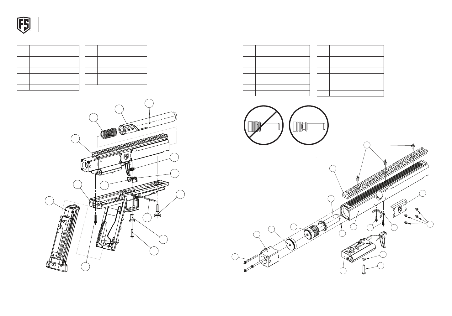
T9.1 ASSEMBLY DIAGRAM
15
13
1
3
2
4
10
8
7
9
11
12
14
16
6
15
5
GUN BODY ASSEMBLY
ITEM NO. NAME
1 Gun Body Assembly
2 Handle
3 Trigger Pin
4 Handle Screw-Front
5 Firing Bolt Spring
6 T9.1 FS Barrel
7 Magazine Assembly
7
ITEM NO. NAME
8 Safety Bushing
9 Safety-Left
10 Safety-Right
11 Safety Spring
12 Shroud Mounting Screw
13 Rubber Nubbin
5
1
2
10
ITEM NO. NAME
1 Engine Assembly
2 T9.1 Gun Body
3 Firing Bolt Assembly
4 Regulator/Trigger Assembly
5 T9.1 Plate Screw
6 Tac Rail - Upper
7 Ammo Release Fork
8 Release Fork Screw
ITEM NO. NAME
9 Reg Body Screw
10 Hopper Cover Plate
11 Reg Body Internal Tooth Washer
12 Rear Body O-RIng
13 Gun Body Cap
14 T9.1 Stock Adapter Assembly
15 Tac Rail Screw-T9.1
16 Stock Adapter Screw
6
13
NOTE: Be sure to install the engine, and push the bolt forward
11
towards nose of gun. It is critical that this is done before
reattaching the regulator assembly.
9
12
3
8
4
18 | T9.1
™
4
19
Page 11
1
6
2
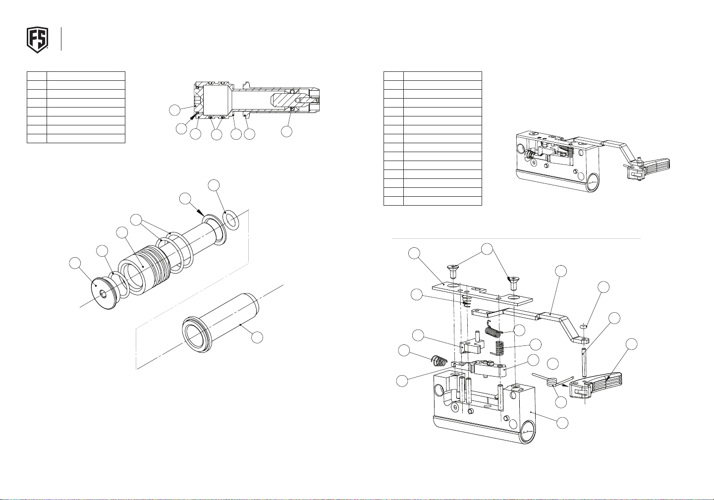
ENGINE & FIRING BOLT ASSEMBLY
C
B
A
8
7
6
5
4
4
TRIGGER GROUP
ITEM NO. NAME
1 Air Chamber Plug
2 Air Chamber
3 AC Shock Absorber
4 AC Cap O-Ring
5 First Strike Firing Bolt
6 AC Plug O-Ring
7 AC OD O-Ring
NOTE: Do not attempt to disassemble bolt and firing pin (Item
5). The alignment is set by factory fixtures and cannot be
reassembled outside the factory.
7
2
6
1
ITEM NO. NAME
1 Trigger
2 Sear
1
6
2
7
5
3
4
3 Rotator
4 Release
5 Push Rod
6 Regulator Body
7 Trigger Spring Pin
8 Sear Spring
9 Rotator Return Spring
10 Release/Rotator Spring
11 Trigger Cover
4
3
5
12 Push Rod O-Ring
13 Trigger Cover Screw
14 Trigger Return Spring
11
10
3
10
13
5
12
7
9
8
2
12
1
20 | T9.1
4
™
14
6
21
Page 12
2
3
9
1
7
16
15
11
14
13
10
12
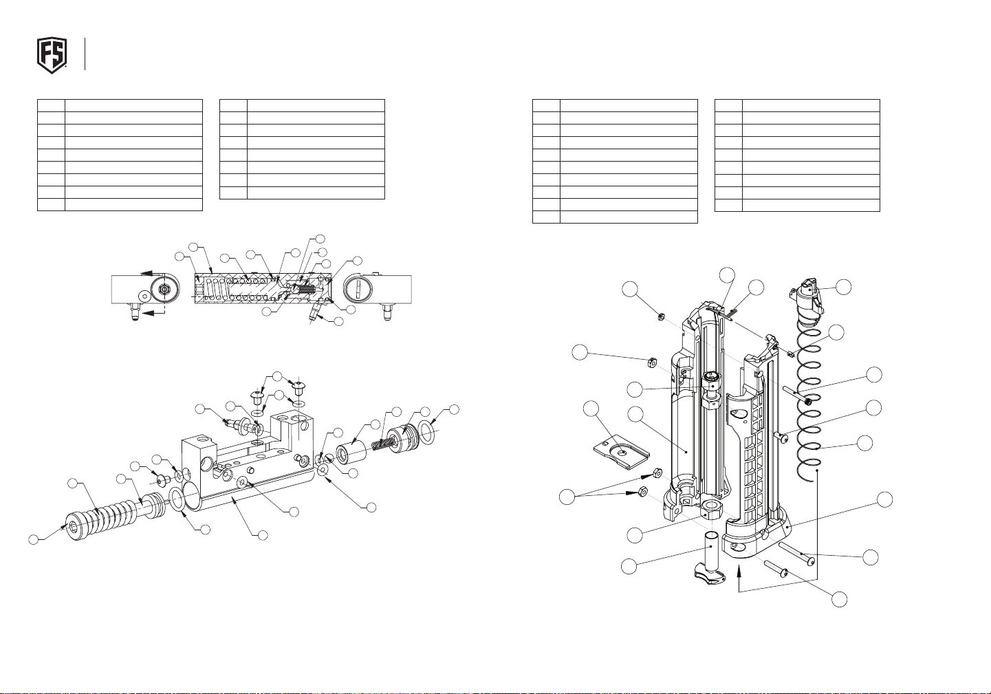
REGULATOR
MAGAZINE
ITEM NO. NAME
1 Regulator Body
2 Regulator Adjuster
3 Stem
4 Regulator Sealing Screw
5 Reg Sealing/Reg Body O-Ring
6 Regulator Spring Pad
7 Regulator Spring Pad O-Ring
8 C02 Stem O-Ring
4
9
2
6
ITEM NO. NAME
9 Regulator Spring
10 Regulator End Screw
11 Regulator Valve Sleeve
12 Regulator Valve O-Ring
13 Regulator End Screw O-Ring
14 Regulator Valve Spring
15 Regulator Valve Ball
ITEM NO. NAME
1 Base Screw
2 CO2 Valve Housing Assembly
3 8.1 Magazine Spring
4 Retainer Pin Cap
5 Magazine Retainer Spring
6 Mag Ball Retainer Pin
7 Magazine Body Nut
8 Magazine UC Nut
ITEM NO. NAME
10 Magazine Screw-UC
11 Magazine Screw-UR
12 CO2 Base Screw Nut
13 Magazine Screw-LR
14 Ball Pusher Assembly
15 Magazine Slide Base
16 Main Magazine Body-L
17 Main Magazine Body-R
9 Magazine Screw-LC
1
2
3
5
7
7
9
12
8
1
NOTE: O-Ring #12 is the same size and color as O-Ring #5 on
Page 24. This O-Ring is harder than the O-Ring on Page 24.
Relief valve is preset at the factory and is not user serviceable.
Consult factory or authorized service center for assistance.
15
11
6
4
5
5
10
14
8
13
3
7
2
14
11
12
15
5
13
10
15
7
16
12
1
6
5
14
4
10
11
3
17
9
13
22 | T9.1
™
23
Page 13
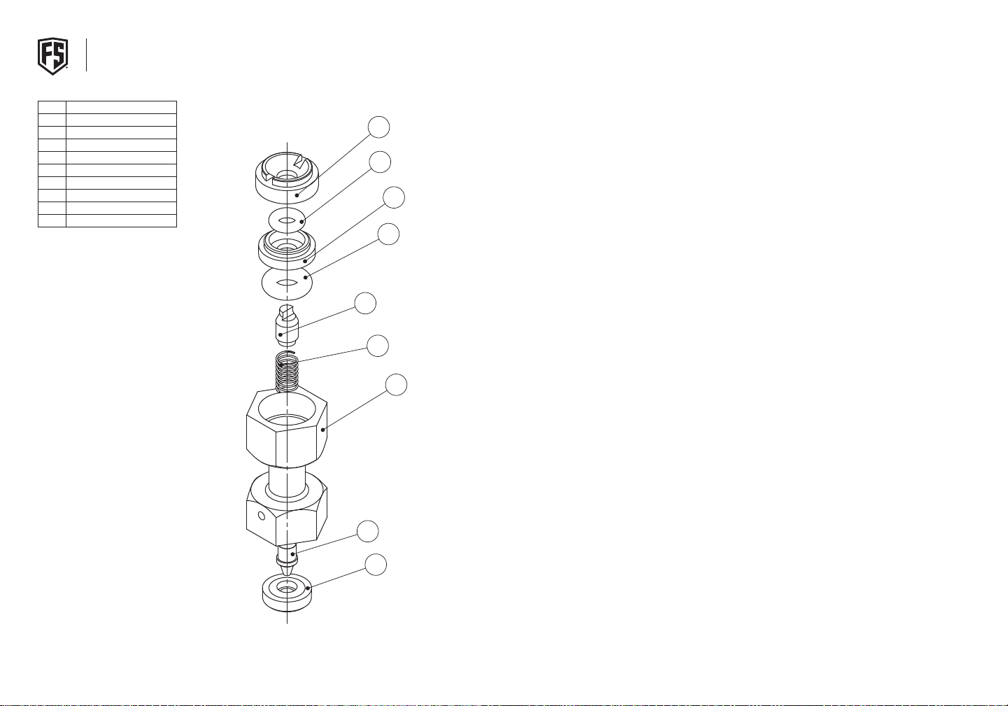
CO2 VALVE HOUSING
TROUBLESHOOTING
ITEM NO. NAME
1 C02 Valve Body
2 C02 Puncture Tip
3 C02 Valve Spring
4 Housing O-Ring
5 C02 Valve Spacer O-Ring
6 C02 Valve Cap
7 C02 Seal
8 C02 Drum Valve
9 Valve Spacer
NOTE: O-Ring #5 is the same size and
color as O-Ring #12 on Page 22. This
O-Ring is softer than the O-Ring on
Page 22.
PAINT BREAKAGE
6
5
9
4
8
3
1
If you experience more than a small number of broken paintballs, then there are 4 things to check:
1. First, be sure that the marker is free of broken paintballs and other debris.
2. Second, make sure that the barrel is locked in its correct position, and that both detents are
installed so that they catch a projectile as it enters the breach.
3. Third, make sure that the red First Strike™ spring is not installed in the magazine (See page 10)
4. Fourth, make sure the maker is set to a reasonable velocity (never over 300 ft. per sec.)
MAGAZINE
If your magazine is leaking CO2, it is coming from one of three seals:
- CO2 seal (#7 - Page 26) - CO2 leaks back toward the CO2 Canister
- CO2 Valve Spacer O-Ring (#5 - Page 24) - CO2 leaks when the magazine is inserted in marker
- Housing O-Ring (#4 - Page 24) - CO2 leaks from the top of the magazine while the magazine isn’t
inside the gun. If the magazine is leaking slightly from this area, try inserting and ejecting into the
maker 2-3 times. This may seat the valve and eliminate the leak.
TRIGGER INSTALLATION
The trigger is equipped with the trigger return spring. When installing the trigger into the grip of the
marker, be sure the trigger and both sides of the spring go through the trigger hole in the grip.
BOLT PUSH
When re-assembling the marker be sure to push the bolt forward before installing the regulator. (See
note on page 19.) To push the bolt the barrel and bolt spring must be removed from the marker.
24 | T9.1
2
7
™
25
Page 14

NOTES
T9.1 WARRANTY REGISTRATION CARD:
NAME:
ADDRESS:
DATE OF PURCHASE:
SERIAL NUMBER:
Please detach from product manual,
place in stamped envelope and send to:
26 | T9.1
First Strike Paintball Warranty Support
2717 Ferguson Rd.
Fort Wayne, IN 46809
"
™
27
Page 15

FIRST STRIKE®
Headquarters:
28101 Ballard Dr. Ste. F
Lake Forest, IL 60045
Manufacturing/Warranty
2717 Ferguson Rd
Fort Wayne, IN 46809
1-260-478-2500
service@first-strike.com
FIRST-STRIKE.COM
© 2017 United Tactical Systems. All rights reserved. This United Tactical Systems product is protected by
United States and International Patents. United Tactical Systems Trademarks, Designs and Copyrights are
protected by United States and International Law. For more information contact United Tactical Systems at
[email protected]
Patent Info here: www.first-strike.com/patents
17/6/22
 Loading...