

Page 1
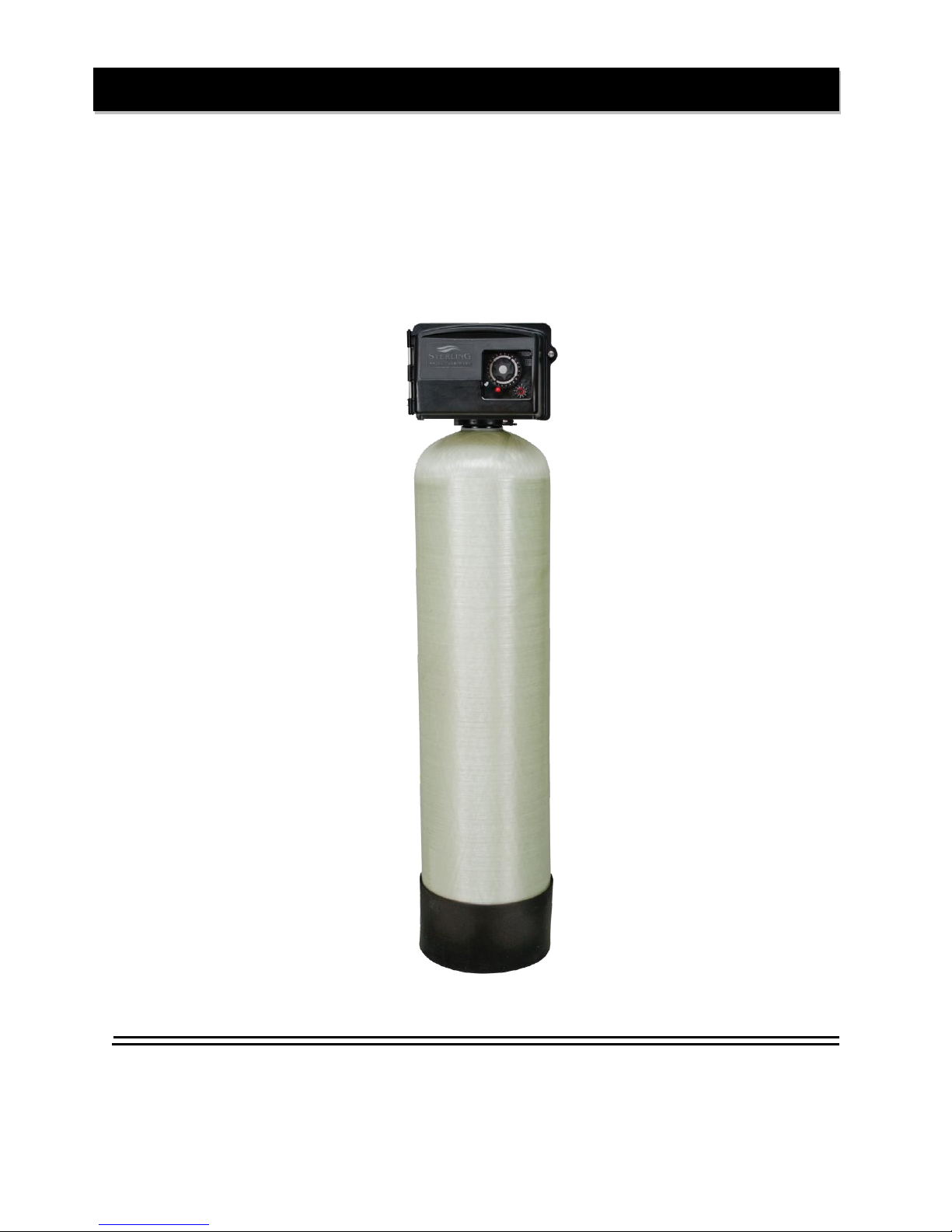
Installation Instructions and Owner’s Manual
FBW Series & FBW ARSENIC Series
Backwashing Filter System
Phone (260) 693-1972 Fax (260) 693-0602
First Sales, LLC
12630 US Highway 33 N
Churubusco, IN 46723
FBW-FBWARS Instruction Manual 170724.docx
Page 2

Pre-installation Instructions
Page 2
Media Types
Page 2
Installation Instructions
Page 5
Timer Operation
Page 8
Maintenance
Page 10
Specifications
Page 12
Component Parts Breakdown
Page 13
Component Parts List
Page 14
Control Valve Breakdown
Page 15
Control Valve Parts List
Page 16
Troubleshooting
Page 17
Control Valve Wiring Diagram
Page 19
Ten Year Limited Warranty
Page 20
Table of Contents
1
Page 3
PART
MEDIA
VOLUME
PACKAGE
SHIP.
WT.
NUMBER
TYPE / APPLICATION
(CU. FT.)
(LBS.)
A10
ACTIVATED CARBON
TASTE & ODOR REDUCTION
1.00
BAG
29
A05P
0.50
PAIL
14
ACC10
CATALYTIC CARBON
CHLORAMINE REDUCTION
1.00
BAG
29
ACC05P
0.50
PAIL
14
B10
BIRM
REDUCTION OF IRON AND
MANGANESE
1.00
BAG
41
B05P
0.50
PAIL
20
C05P
CALCITE
SELF LIMITING ACID
NEUTRALIZER
0.50
PAIL
45
FA10
FILTER – AG
SUSPENDED SOLIDS
REDUCTION
1.00
BAG
24
FA05P
0.50
PAIL
12
ZEO10
ZEOLITE
SUSPENDED SOLIDS/
SEDIMENT REDUCTION
1.00
BAG
25
Z05P
0.50
PAIL
50
N05
NEUTRALIZER
ACID NEUTRALIZER
0.50
PAIL
43
QFS05P
QUARTZ FILTER SAND
0.50
PAIL
51
(.45mm x .55mm)
SEDIMENT REDUCTION
Pre-installation Instructions
Description of the backwashing filter
The FBW system includes a filtration tank (with gravel and distributor) and a backwashing control valve with
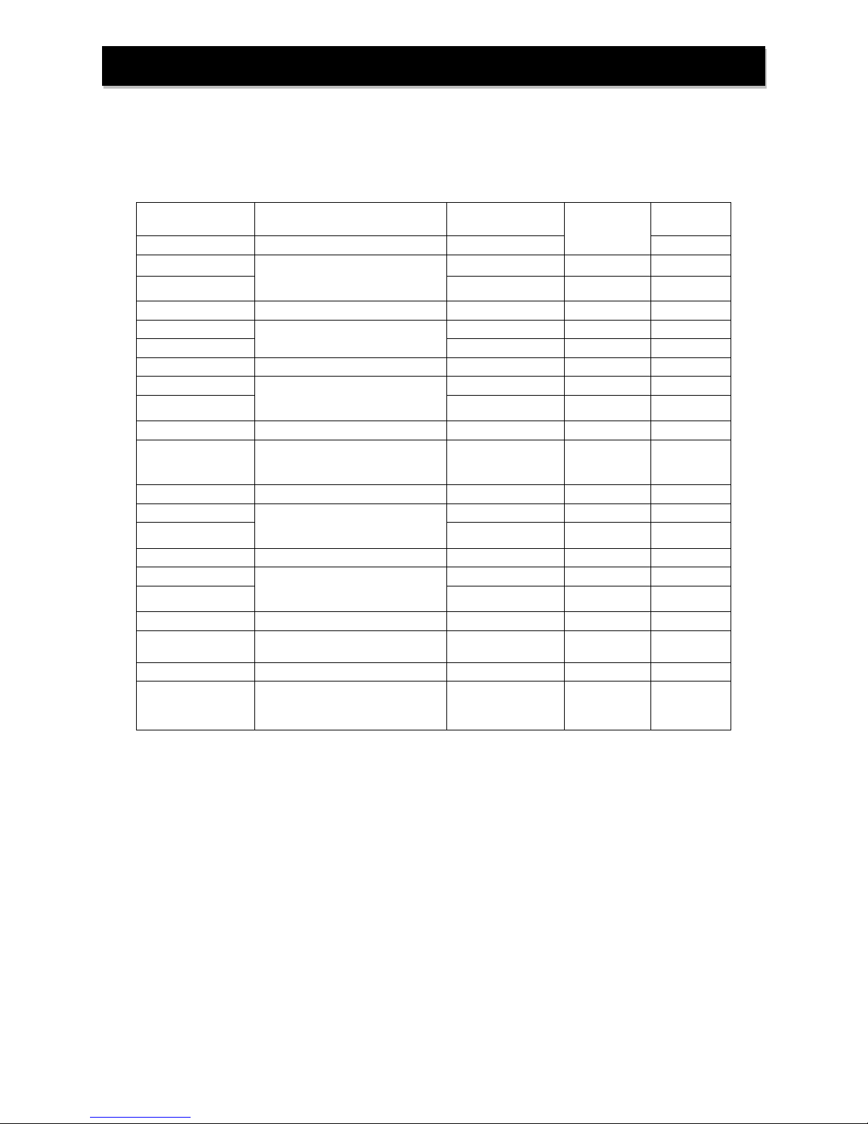
bypass. Filtration media for use with the FBW system is purchased separately and selected from the following
types:
The FBW ARSENIC system includes a filtration tank (with gravel and distributor), arsenic reduction media
(shipped separately) and a backwashing control valve with bypass. The media is included with the unit for FBW
ARSENIC unit only.
2
Page 4

Draw Down (gallons)
X
60 = Pumping Rate (gallons per minute)
Cycle Time (seconds)
8 gallons
X
60
=
7.4 gpm (gallons per minute)
65 seconds
Pre-installation Instructions (cont.)
Successful Application
Any filter media may have specific limitations and/or requirements for successful application. A water sample
should be submitted to First Sales for analysis and recommendation by Customer Service.
FBW ARSENIC IMPORTANT: Contact First Sales technical services to assist with proper
sizing based on the level of arsenic in the water and the flow rate requirement. The arsenic
test results must be from a certified laboratory to ensure accuracy. Other water quality
information is required as well, and will determine if pre-treatment equipment is required to
meet the influent water quality pre-requisites for the FBW ARSENIC system: Iron < 0.3 ppm,
Manganese < 0.05 ppm, pH < 8.0, Silica < 30 ppm, Hardness > 5 gpg is preferred but not
required.
Once the system has been installed, an arsenic test should be done to determine if the
arsenic level is being reduced sufficiently (10 ppb or less, per the EPA MCL) and should be
tested regularly (every 6 months recommended) to ensure the system is functioning properly
and to indicate when the media has become exhausted.
Time of Backwash
Periodically the control valve will go through a backwash cycle. This cycle is factory preset to 12:00 A.M.
flushing the accumulated sediment and/or precipitant to the drain. After the backwashing process the unit is
now prepared for the next period of service.
Water Supply
This filter will function properly when the water supply is furnished by a jet pump, submersible pump, variable
speed (constant pressure) pump or community water supply. As with all other filter systems, however, it is
imperative that the well pump provides enough flow rate for the filter to adequately backwash. In order to
ensure sufficient backwash flow rate the following pumping rate test should be performed prior to installing the
FBW or FBW ARSENIC system.
1. Make certain no water is being drawn in the house.
2. Open spigot nearest pressure tank.
3. When well pump starts, close spigot and measure time (in seconds) to refill pressure tank (well pump
turns back off). This is Cycle Time.
4. Using a container of known volume, draw water from pressure tank and measure how many gallons
until the pump turns back on again. This is Draw Down.
5. Calculate pumping rate by dividing draw down by cycle time and multiplying by 60.
Example: Draw down is 8 gallons
Cycle time is 65 seconds
3
Page 5
Water Heater
Untreated Water
Untreated Water for
geothermal heat pumps,
swimming pools, lawn
irrigation, hose bibs etc.
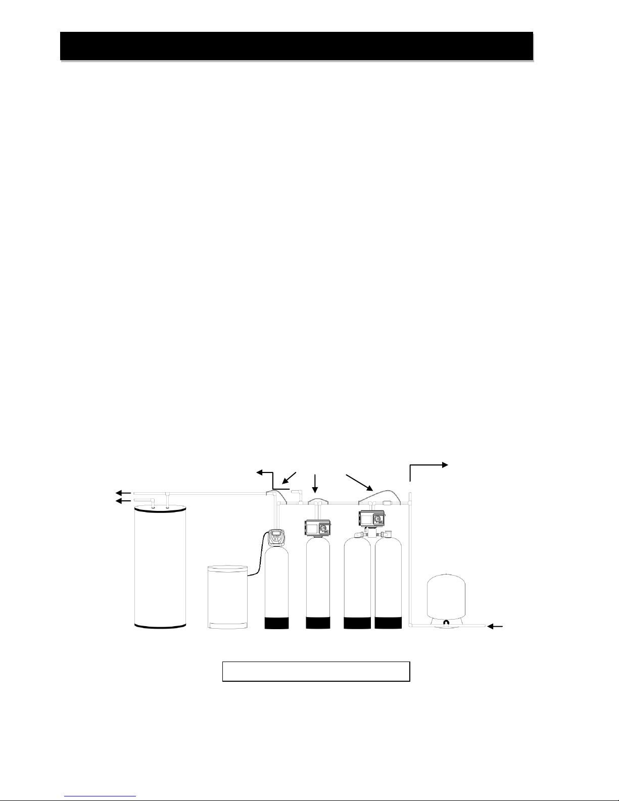
FIGURE 1: Typical Installation
Filtered Hard Water
Iron Filter
(if required)
Softener
Brine Tank
Pressure Tank
Treated Water
Grounding Strap
Pre-installation Instructions (cont.)
FBW/FBW
ARSENIC
Location Considerations
The proper location to install the FBW/FBW ARSENIC will ensure optimum filter performance and satisfactory
water quality. The following factors should be considered in selecting the location of this system.
1. The FBW/FBW ARSENIC must be installed after the pressure tank (private well system only).
2. The system should be installed as close as possible (preferably within 15’) to an adequate floor or
laundry drain capable of handling the backwash cycle volume and flow rate (refer to unit
specifications). An air gap should be provided between the FBW drain line and plumbing drain.
3. All water conditioning equipment should be installed at least 10’ prior to the water heater. Water
temperatures exceeding 100°F can damage the internal components of the control valve and filter
tank. An expansion tank may need to be installed in the line to the water heater in order to allow for
thermal expansion and comply with local plumbing codes.
4. Water pressure must not exceed the range of 25 - 100 psi.
5. The system must not be subject to freezing temperatures.
6. The control valve requires 115/120 V, 60 Hz electricity from a three prong outlet that is not wired to
a switch.
7. Never install a cartridge type filter prior to the FBW/FBW ARSENIC. Any cartridge or in-line filter (if
desired) may be installed after the FBW/FBW ARSENIC system. This will prevent restricting the
water flow and pressure available for backwash.
8. Appliances requiring extended periods of continuous or high flow water use (i.e. geothermal heat
pumps, swimming pools, lawn irrigation, outside hose bibs, etc.) should bypass the filter.
Typical Installation
4
Page 6
Installation Instructions
FIGURE 2: Top View of Control Valve
STEP 1: Unpack FBW/FBW ARSENIC filter unit, making sure to remove entire contents of the shipping
container prior to disposal.
STEP 2: With the FBW/FBW ARSENIC filter unit in the upright position, remove the control valve from
the mineral tank being careful to not pull the distributor out of the gravel at the bottom of
the tank.
STEP 3: Cover the top of the distributor tube with the included red cap and, using the included blue
media funnel, pour filter media(s) into the mineral tank. If using multiple filter media types, load
in the order of heaviest (most dense) to lightest (least dense). 12” – 14” of space MUST be left
empty at the top of the mineral tank to allow for media bed expansion during backwash and to
prevent filter media from being discharged through the drain line.
STEP 4: Use a garden hose or bucket to fill the media tank with water.
STEP 5: Clean mineral tank threads to remove any filter media. Remove red cap from distributor tube
and reinstall control valve by threading it securely onto the mineral tank. (O-ring seal; HAND
TIGHTEN ONLY!).
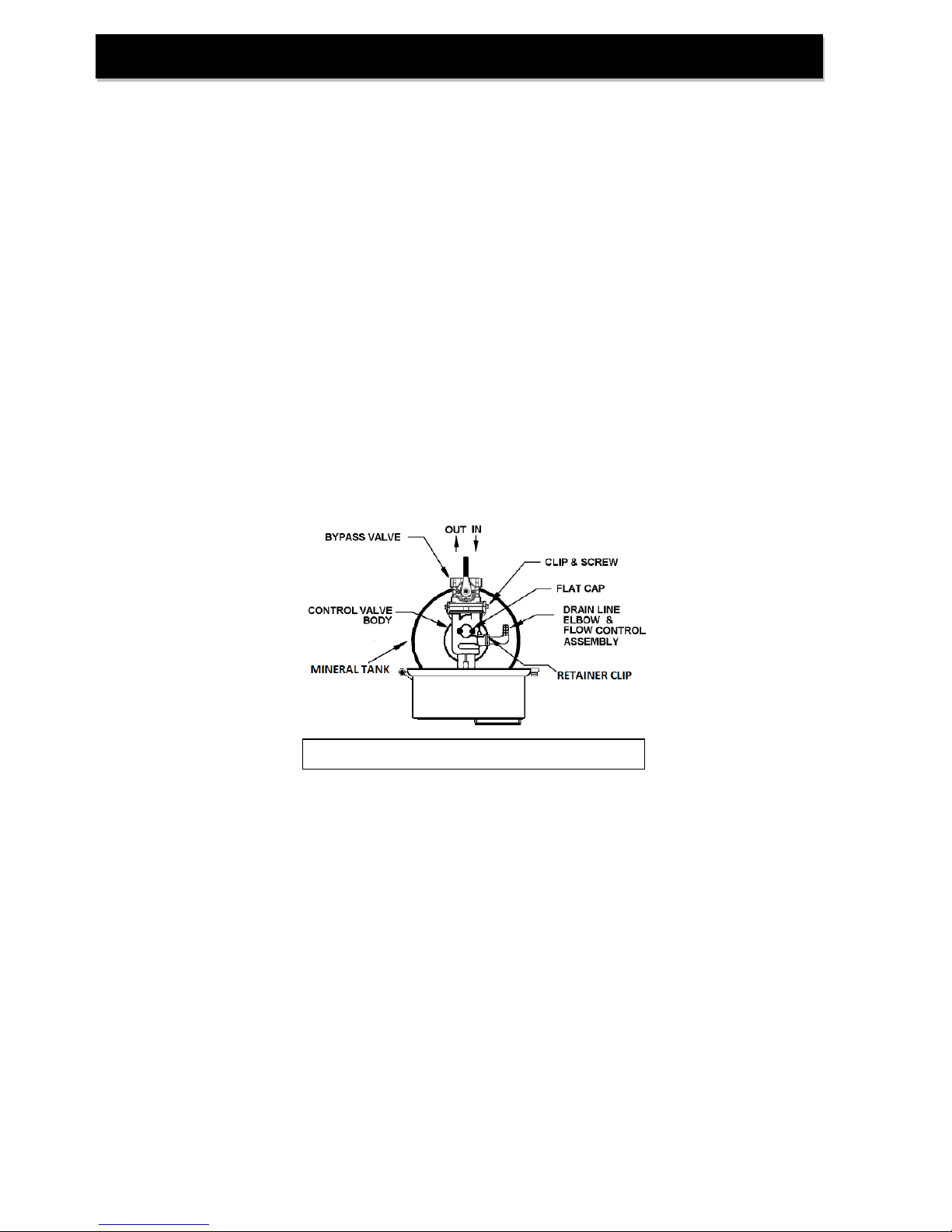
STEP 6: Use clips and screws provided and attach bypass valve to the inlet/outlet of the control valve.
See Figure 2 below.
STEP 7: Shut off all water at main supply. On private well system, turn off power to pump and drain
pressure tank. Make certain pressure is relieved from complete system by opening nearest
faucet to drain system. SHUT OFF FUEL / ELECTRICAL SUPPLY TO WATER HEATER.
STEP 8: Cut main supply line as required to fit plumbing to inlet and outlet of bypass valve. DO NOT
PLUMB INLET AND OUTLET BACKWARDS. Piping should be supported. Do not apply heat
to any fitting attached to the bypass or control valve. Perform all plumbing according to local
plumbing codes.
STEP 9: Attach plumbing. DO NOT apply heat to any fitting connected to bypass valve or control valve,
as damage may result to internal parts or connecting adapters. MAKE CERTAIN WATER
ENTERS THROUGH INLET AND DISCHARGES THROUGH OUTLET.
5
Page 7
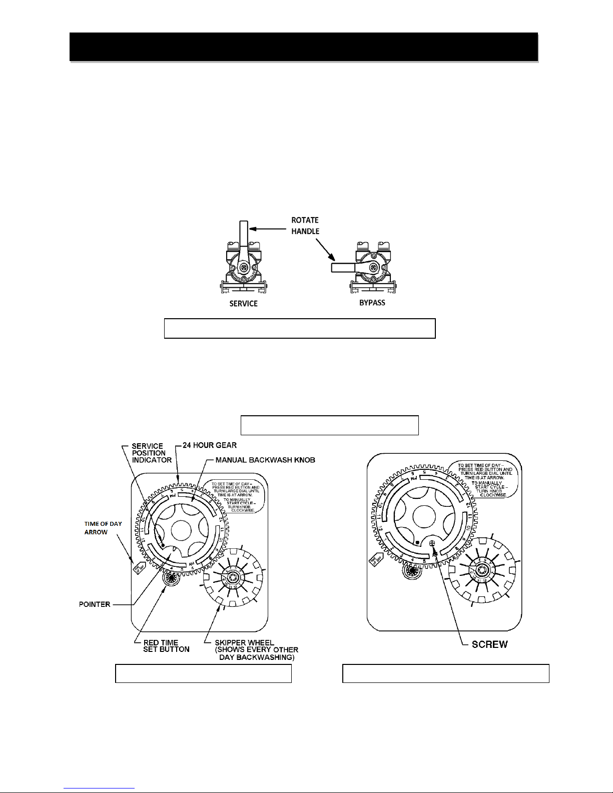
Backwash Timer Control
FIGURE 4a: Timer in Service Position
FIGURE 4b: Adjusting Time of Regeneration
Installation Instructions (cont.)
FIGURE 3: Stainless Steel Bypass Valve Operation
STEP 10: Use polyethylene drain line tubing provided (NO VINYL TUBING) to run drain line from control
valve discharge fitting to floor drain or sump pit capable of handling the backwash rate of the
filter (refer to specifications and flow rate on page 12). DISCHARGE END OF THE DRAIN
LINE MUST BE FIRMLY SECURED! There must be an air gap at the end of the drain line to
prevent siphoning of waste water and meet plumbing code. Total length of drain line should
be 15’ or less. AVOID OVERHEAD DRAINS.
STEP 11: Place bypass in the “Bypass” position (refer to Figure 3 below). Open main supply valve or turn
on power to pump on private well systems.
STEP 12: Plug the power cord into an un-switched electrical outlet.
STEP 13: Initiate a manual regeneration by turning the Manual Backwash Knob clockwise until the knob
engages the program wheel. You should hear one click. This is the “Backwash” position.
Then, unplug the control valve from the electrical outlet to prevent it from advancing
automatically.
STEP 14: Refer to Figure 3 (page 6) for appropriate bypass valve operation. Rotate bypass lever of
stainless steel bypass ¼ of the way to Service or until air and/or water begins to flow slowly to
drain.
6
Page 8

Installation Instructions (cont.)
STEP 15: IMPORTANT: Activated Carbon, Filter Ag and Birm must be soaked for at least 2 hours
prior to submitting it to full flow rate to prevent loss of media to drain. Once the air is
purged, fully open the bypass valve to the “Service” position (Figure 3, Page 4) and leave the
control valve in “Backwash” position for at least 10 minutes or until water flowing from the drain
line runs clear; whichever is longer.
STEP 16: Plug the power cord back into an un-switched electrical outlet.
Manually advance the control valve to the “Service” position (Figure 4a) by turning the Manual
Backwash Knob clockwise and reconnect the control valve to the electrical outlet. Check for
and resolve any leaks in the unit or connected plumbing.
STEP 17: Set the Timer Control (Figure 4a) by rotating the Skipper Wheel (Figure 4a) so the red pointer
is directly over day 1. Select the days when backwashing will occur by sliding the metal tabs in
or out. IN indicates no backwashing will occur on that day, OUT indicates that backwashing
will occur on that day. Factory setting is to initiate backwash every third day.
IMPORTANT: Raw water quality determines the frequency of backwashing required. It is
recommended that the unit be backwashed NO LESS THAN every 6 days. If pressure drop
increases or contaminants are detected in the filtered water, backwashing frequency MUST be
increased. Filters with Calcite or Neutralizer media should be backwashed AT LEAST EVERY
OTHER DAY to prevent the media particles from “cementing” together.
STEP 18: Set the current time of day by depressing the red Time Set Button (Figure 4a) and turning the
24 Hour Gear (Figure 4a) to the desired time (note AM and PM).
STEP 19: Time of Regeneration is factory set to 12:00 A.M. To adjust the time of regeneration:
a) Unplug control valve from electrical outlet.
b) Locate three screws (Figure 4b) behind the Manual Backwash Knob (Figure 4a) by
pushing the red Time Set Button (Figure 4a) and rotating the 24 Hour Gear (Figure
4a) until each screw appears in the cut out portion of the Manual Backwash Knob.
c) Loosen each screw slightly to release the pressure on the time plate of the 24 Hour
Gear
d) Continue depressing the red Time Set Button and rotate the 24 Hour Gear to
expose the Regeneration Time Pointer (Figure 4a) in the cut out portion of the Manual
Backwash Knob. Keep the Regeneration Time Pointer visible in the cut out while
rotating only the time plate until the desired time of regeneration (note AM and PM) is
aligned with the Regeneration Time Pointer.
e) Continue depressing the red Time Set Button and rotate the 24 Hour Gear along
with the Time Plate until each screw has been exposed in the cut out portion of the
Manual Backwash Knob and re-tightened. DO NOT OVERTIGHTEN. Make certain
that the backwashing filter DOES NOT regenerate at the same time with any other
water treatment equipment.
STEP 20: Turn on fuel/electrical supply to water heater.
RECOMMENDED: Retain the red distributor cap and blue media funnel for future replenishment of filter media.
NOTE: If the FBW filter is loaded with any self-sacrificing media like Calcite or Neutralizer, mark the
media level on the side of the tank by shining a bright light through the tank to see its level. Replenish
the media in the mineral tank when the level drops by more than three inches.
7
Page 9
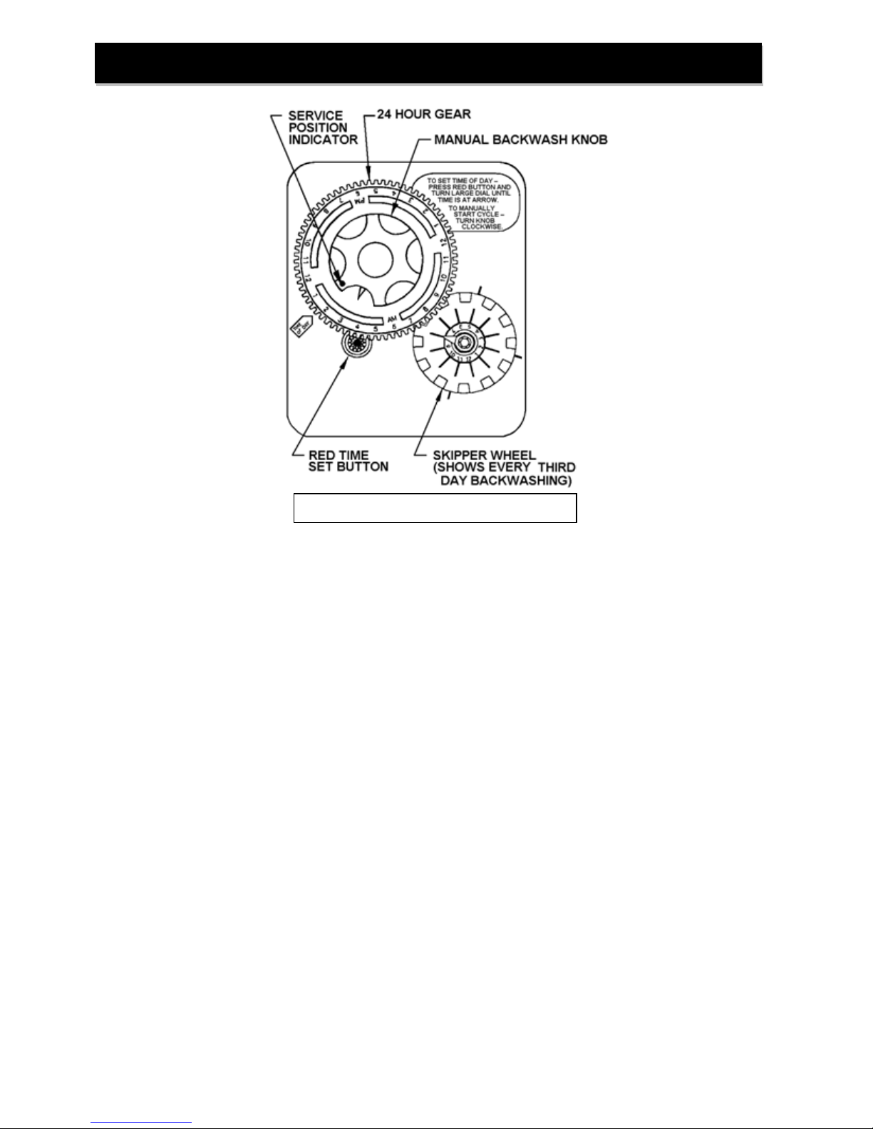
Timer Operation
FIGURE 5: Front of Timer Assembly
How to set Time of Day:
1. Press and hold the red button to disengage the drive gear.
2. Turn the large 24 hour gear until the actual time of day is at the time of day pointer.
3. Release the red button to again engage the drive gear.
How to set the Days of Backwash:
1. Rotate the skipper wheel until the number 1 is at the red pointer.
2. Each number represents a day. The number by the red pointer is tonight.
3. Slide the metal tabs outward on the desired days of regeneration.
How to Manually Initiate a Backwash Cycle:
1. Grab the manual regeneration knob and turn clockwise.
2. The drive gear will engage the program wheel and make a complete revolution through the
backwash cycle.
3. The backwash knob will make a complete revolution and return to the home position after the
backwash cycle.
8
Page 10
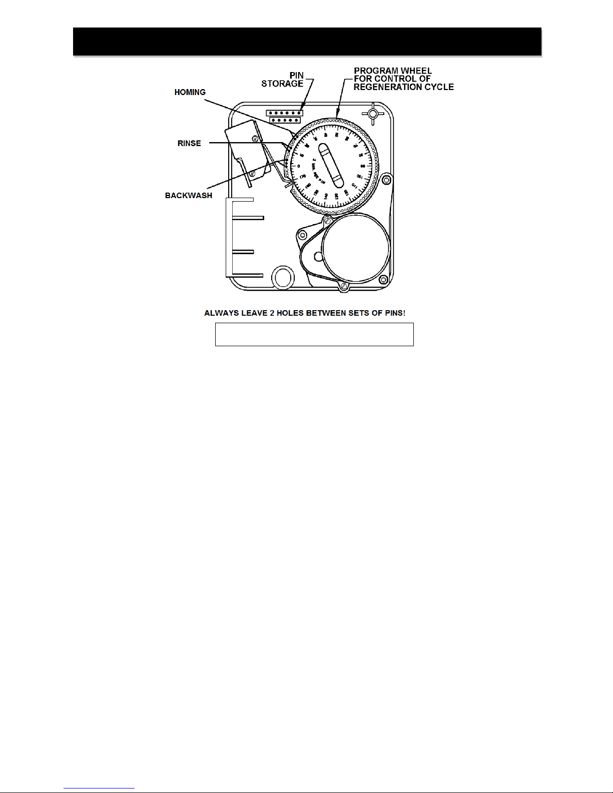
FIGURE 6: Back of Timer Assembly
Timer Operation (cont.)
How to Change the Length of Backwash Cycles:
All cycles have been factory set and should not need adjustment. If local conditions require different
cycle lengths, however, the following procedures should be followed.
1. Grasp top left corner of timer assembly and pull to swing timer open and expose the program
wheel.
2. Remove program wheel from timer by squeezing retaining lugs in center of program wheel.
Maneuver program wheel away from micro switch arms and timer assembly.
3. BACKWASH cycle may be lengthened by adding pins to 1st set of pins on program wheel. Each
pin will equal 2 minutes of backwash time. The remaining two sets of pins MUST also be
shifted clockwise to ensure 2 holes separate each cycle.
4. RAPID RINSE cycle may be lengthened by adding pins to the 2nd set of pins on the program
wheel. Each pin represents 2 minutes of rapid rinse time. The last set of pins MUST also be
shifted clockwise to ensure 2 holes separate each cycle.
5. Reinstall the program wheel on the retaining lugs by maneuvering past the micro switch arms.
6. Close and latch the timer assembly. Ensure that the retainer snaps into the hole in the back plate
and all electrical wiring is ABOVE the timer post.
9
Page 11

Maintenance
1) At least every six months you should check the time of day setting. Power outages will cause the units
time clock to be inaccurate and backwashing will not occur at the planned time.
2) If your unit contains activated carbon, you must replace the carbon and gravel underbed at least every
three years. Replacement may be required sooner if the taste and odor being removed begins to
reappear in the treated water or you experience increasing pressure drop that is not resolved by
increasing the frequency of backwashing.
3) Filter Ag and Filter Sand will last indefinitely. It may be necessary to replace them if you experience
increasing pressure drop that is not resolved by increasing the frequency of backwashing or if water
quality diminishes due to contaminant bleed through.
4) Neutralizer media or calcite must be replenished at least annually. Mark the side of the mineral tank at
installation so the drop in media level may be monitored by shining a bright light behind the mineral
tank. Add media if the level has dropped by more than three inches.
5) Birm should be replaced when iron reappears in the treated water and backwashing does not improve
the water quality.
6) For the FBW ARSENIC test the treated water for arsenic every 6 months to ensure the system is
functioning properly and to identify when the arsenic reduction media has become exhausted.
Satisfactory test results will be 10 ppb of arsenic or less. If unsatisfactory the filter will need to be rebedded.
TO REPLENISH OR REBED MEDIA:
1) Pressure must be relieved on the system by placing the bypass valve in the “Bypass” position (Figure
3) and rotating the manual backwash knob (Figure 4a) clockwise until the knob engages the program
wheel and water flows briefly to drain. Once water has stopped flowing to drain move on to next step.
2) Unplug the control valve from the electrical outlet to prevent it from advancing automatically.
3) Disconnect the control Valve from the bypass valve
4) Disconnect the drain line from the control valve
5) Unscrew control valve from mineral tank (IF REBEDDING ONLY - remove the distributor).
6) Siphon water from mineral tank (IF REBEDDING ONLY - Remove existing media and gravel).
7) IF REBEDDING ONLY - Rinse mineral tank and replace distributor, making certain that the
distributor basket sits in the center of the tank bottom.
8) Cover the top of the distributor tube to prevent media entering the tube during filling. Using a funnel,
pour filter media(s) into the mineral tank. (IF REBEDDING ONLY - Begin loading tank with the
gravel underbed. Filling the mineral tank 1/3 with water before loading gravel will cushion the
fall and ensure even distribution of the gravel and media. If using multiple filter media types,
load in the order of heaviest {most dense} to lightest {least dense}.) 12” – 14” of space MUST be
left empty at the top of the mineral tank to allow for media bed expansion during backwash and to
prevent filter media from being discharged through the drain line.
10
Page 12

Maintenance (cont.)
9) Use a garden hose or bucket to fill the media tank with water.
10) Clean mineral tank threads to remove any filter media. Uncover distributor tube and reinstall control
valve by threading it securely onto the mineral tank. (O-ring seal: HAND TIGHTEN ONLY!)
11) Attach bypass (Figures 2 & 3) to control valve body.
12) Re-attach drain line to control valve.
13) IMPORTANT: Activated Carbon, Filter Ag and Birm must be soaked for at least 2 hours prior to
submitting it to full flow rate to prevent loss of media to drain.
14) Open the bypass valve only 1/4 of the way to the “Service” position (Figure 3, Page 4). Any air trapped
in the media bed should begin purging to the drain and water should begin flowing slowly to the drain.
15) Once the air is purged, fully open the bypass valve to the “Service” position (Figure 3, Page 4) and
leave the control valve in “Backwash” position for at least 10 minutes or until water flowing from the
drain line runs clear; whichever is longer.
16) Plug the power cord back into an un-switched electrical outlet.
17) Manually advance the control valve to the “Service” position (Figure 4a) by turning the Manual
Backwash Knob clockwise. Check for and resolve any leaks in the unit or connected plumbing.
11
Page 13
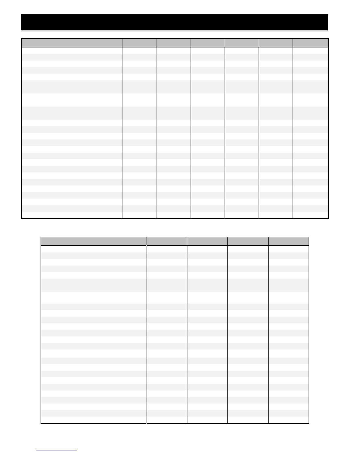
Description
FBW10
FBW15
FBW20
FBW25
FBW30
FBW40
Filter Media Volume, cu. ft.
1.0
1.5
2.0
2.5
3.0
4.0
Gravel Underbed, lbs.
20
20
25
25
50
50
Operating Flow Rate, gpm
Continuous
(no duration limit, 5 gpm/ft2)
2
3
4
5
5
7
Service
(intermittent flow up to 10 gpm/ft2)
5
6
8
9
11
14
Peak
(10 mins. or less, 15 gpm/ft2)
8
9
12
14
16
21
Backwash Flow Rate, gpm
5
5
7
7
10
10
Service Pipe Size, in.
Standard
¾ ¾ ¾ ¾ ¾
¾
-1 Suffix on Model Number
1 1 1 1 1
1
Tank Diameter x Height, in.
10 x 44
10 x 54
12 x 48
13 x 54
14 x 65
16 x 65
Minimum Space Required, in.
Width
12
12
13
14
15
17
Depth
15
15
15
15
15
17
Height
54
64
58
64
75
75
Approximate Ship Wt., lbs.
49
52
60
75
99
115
(Media Not Included)
Description
FBW10ARSENIC
FBW20ARSENIC
FBW30ARSENIC
FBW40ARSENIC
Filter Media Volume, cu. ft.
1.0
2.0
3.0
4.0
Gravel Underbed, lbs.
20
25
50
50
Operating Flow Rate, gpm
Service (10 gpm/ft2 media surface)
*<=30ppb **<=40ppb ***<=50ppb
6*
8**
11***
14***
Peak (<=15 psi loss)
Exceeding peak flow can damage the media!
11
12
13
14
Backwash Flow Rate, gpm
5 7 9
10
Pressure Loss, psi
@ Service
5 8 11
15
@ Peak
12
14
14
15
Service Pipe Size, in.
Standard
¾ ¾ 1
1
-1 Suffix on Model Number
1 1 -NA-
-NA-
Tank Diameter x Height, in.
10 x 44
12 x 48
14 x 65
16 x 65
Minimum Space Required, in.
Width
12
13
15
16
Depth
15
16
17
18
Height
54
58
75
75
Approximate Ship Wt., lbs.
112
168
287
343
Specifications
12
Page 14
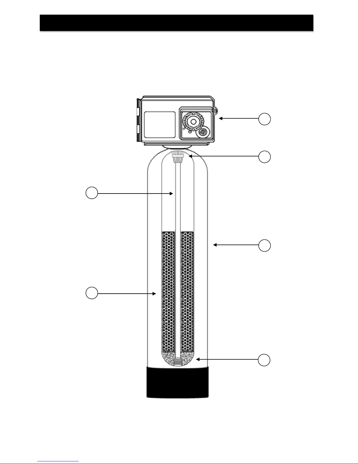
3 1 4 5 6
2
Component Parts Breakdown
13
Page 15
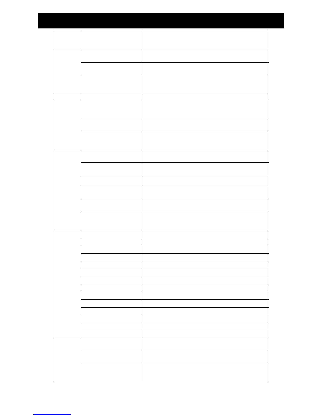
Ref #
Part Number
Description
1
FBW10 Vlv Assy L/BP
Control Valve, Cover, 5.0 GPM DLFC, less bypass
for models FBW10, FBW15, & FBW10ARSENIC
FBW20 Vlv Assy L/BP
Control Valve, Cover, 7.0 GPM DLFC, less bypass
for model FBW20, FBW25, & FBW20ARSENIC
FBW30 Vlv Assy L/BP
Control Valve, Cover, Blank DLFC, less bypass for
model FBW30, FBW40, FBW30ARSENIC, &
FBW40ARSENIC
2
18280-02
Top Screen, Bayonet Style
3
D100S-48
Distributor Tube, 1" x 48"
for models FBW10, FBW20, FBW10ARSENIC, &
FBW20ARSENIC
D100S-54
Distributor Tube, 1" x 54"
for model FBW15 & FBW25
D100S-65
Distributor Tube, 1" x 65"
for model FBW30, FBW40, FBW30ARSENIC, &
FBW40ARSENIC
4
MTP1044N
10 x 44 Mineral Tank, Nat, Base, 2.5" Top Opening
For model FBW10 & FBW10ARSENIC
MTP1054N
10 x 54 Mineral Tank, Nat, Base, 2.5" Top Opening
For model FBW15
MTP1248N
12 x 48 Mineral Tank, Nat, Base, 2.5" Top Opening
For model FBW20 & FBW20ARSENIC
MTP1354N
13 x 54 Mineral Tank, Nat, Base, 2.5" Top Opening
For model FBW25
MTP1465N
14 x 65 Mineral Tank, Nat, Base, 2.5" Top Opening
For model FBW30 & FBW30ARSENIC
MTP1665N-4.0
16 x 65 Mineral Tank, Nat, Base, 4.0" Top Opening
For model FBW40 & FBW40ARSENIC
(SF4821-2 4x2.5 bushing also required)
5*
A10
Activated Carbon, 1.00 cu. ft. bag
A05P
Activated Carbon, 0.50 cu. ft. pail
ACC10
Catalytic Carbon, 1.00 cu. ft. bag
ACC05P
Catalytic Carbon, 0.50 cu. ft. pail
ARSENIC-10
Arsenic Media, 1.00 cu. ft. bag (FBW-ARSENIC)
B10
Birm, 1.00 cu. ft. bag
B05P
Birm, 0.50 cu. ft. pail
C05P
Calcite, 0.50 cu. ft. pail
FA10
Filter Ag, 1.00 cu. ft. bag
FA05P
Filter Ag, 0.50 cu. ft. pail
ZEO10
Zeolite 1.00 cu. ft. bag
Z05P
Zeolite 0.50 cu. ft. pail
N05
Neutralizer, 0.50 cu. ft. pail
QFS05P
Quartz Filter Sand, 0.50 cu. ft. pail
6
QC20
1/4" x 1/8" Gravel, 20 lb Pail
for models FBW10, FBW15, & FBW10ARSENIC
QC25
1/4" x 1/8" Gravel, 25 lb Pail
For models FBW20, FBW25, & FBW20ARSENIC
QC50
1/4" x 1/8" Gravel, 50 lb Bag
For models FBW30 , FBW40, FBW30ARSENIC, &
FBW40ARSENIC
Component Parts List
*Filter media sold seperately. Select appropriate media for water condition (page 2).
14
Page 16
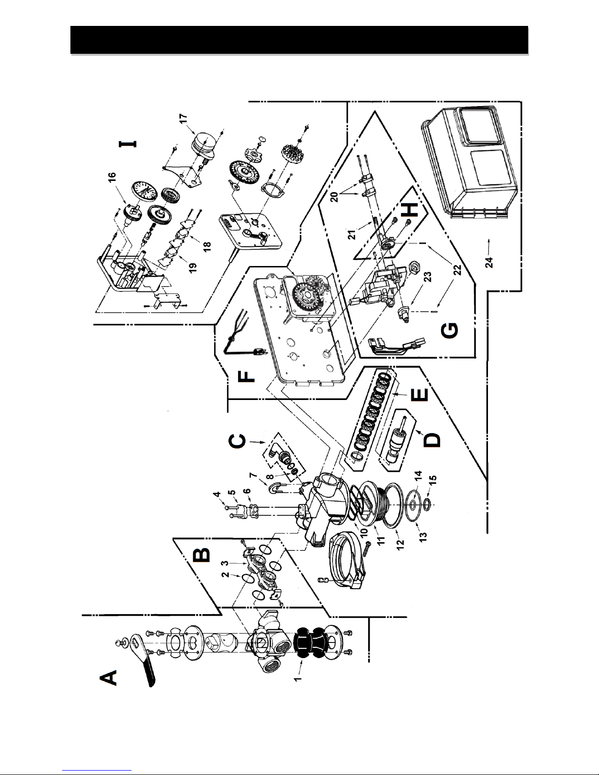
Control Valve Breakdown
15
Page 17
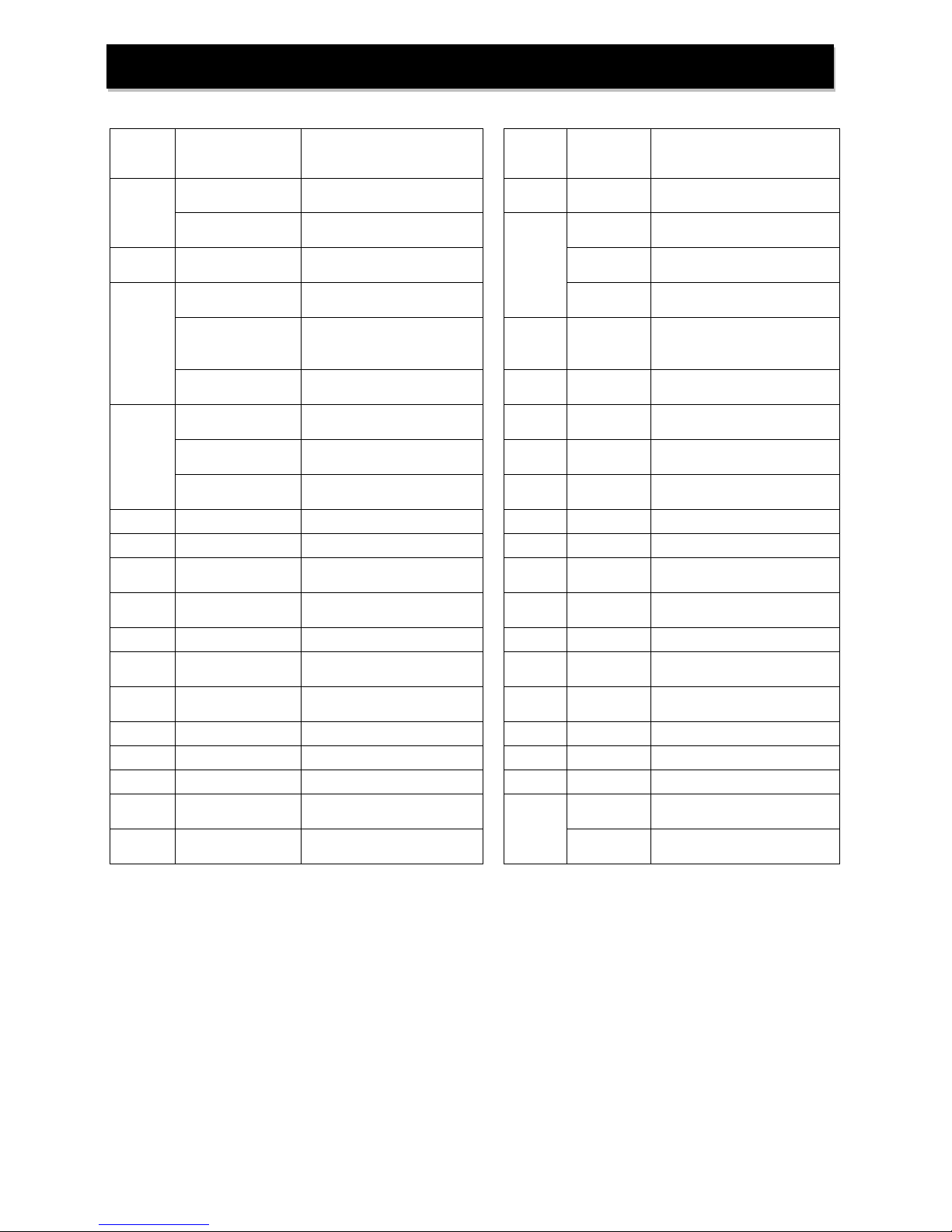
REF #
Part Number
Description
REF #
Part
Number
Description
A
60040SS
Stainless Steel Bypass, 3/4”
FPT (Standard)
7
18312
Retainer, Drain
60041SS
Stainless Steel Bypass, 1”
FPT (Optional, “-1S” suffix)
8
12092
5.0 gpm DLFC
(FBW10 &FBW15)
B
60900-41
Coupling Kit
12408
7.0 gpm DLFC
(FBW20 & FBW25)
Not
Shown
60705-50
5.0 gpm DLFC Housing
(Old Style for 1 & 1.5 cu ft)
-NA-
No DLFC used
(FBW30 & FBW40)
60705-70
7.0 gpm DLFC Housing
(Old Style for 2 & 2.5 cu ft)
Not
Shown
12338
Drain Fitting, Hose Barb, 90
Deg Elbow, 1/2" x 1/2" (Old
Style)
60705-00
Blank DLFC Housing
(Old Style for 3 & 4 cu ft)
10
19936
Base Seal (2510)
C
60705-50A
5.0 gpm DLFC Elbow
(New Style for 1 & 1.5 cu ft)
11
19322
2510 Adapter Base
60705-70A
7.0 gpm DLFC Elbow
(New Style for 2 & 2.5 cu ft)
12
19197
Slip Ring
60705-00A
Blank DLFC Elbow
(New Style for 3 & 4 cu ft)
13
18303
Tank O-Ring, 2510 Valve
D
60090
Piston Assembly
14
13304
Distributor O-Ring, -121
E
60121
Seal and Spacer Kit
15
13030
Distributor Retainer
F
FV2510-1PH
Power Head Assembly,
2510 TC with Cover
16
13911
Main Drive Gear
G
60050-21
Drive Motor Assembly
17
18743-1
Timer Motor, 120v/60Hz,
2510/5600 Valve
H
60160-10
Drive Cam Assembly, STF
18
15320
Micro Switch, Homing
I
60304-13
Timer Assembly, 3200, 12
Day, STF, 120/60
19
10896
Micro Switch, Step
1
14105
Bypass Valve Seal, Single
Lever
20
10218
Micro Switch, Drive Motor
2
13305
Coupling O-Ring, -019
21
10909
Connecting Link Pin
3
19228-01
Coupling, Adapter S/ASSY
22
10338
Roll Pin 4 10692
Injector cover screw
23
12777
Brine Cam, STF
5
11893
Injector Cover
24
60219-02
Valve Cover, Environmental
(Old Style)
6
14805
Injector Body Gasket
SCA-926
Valve Cover, Environmental
(New Style)
Control Valve Parts List
16
Page 18
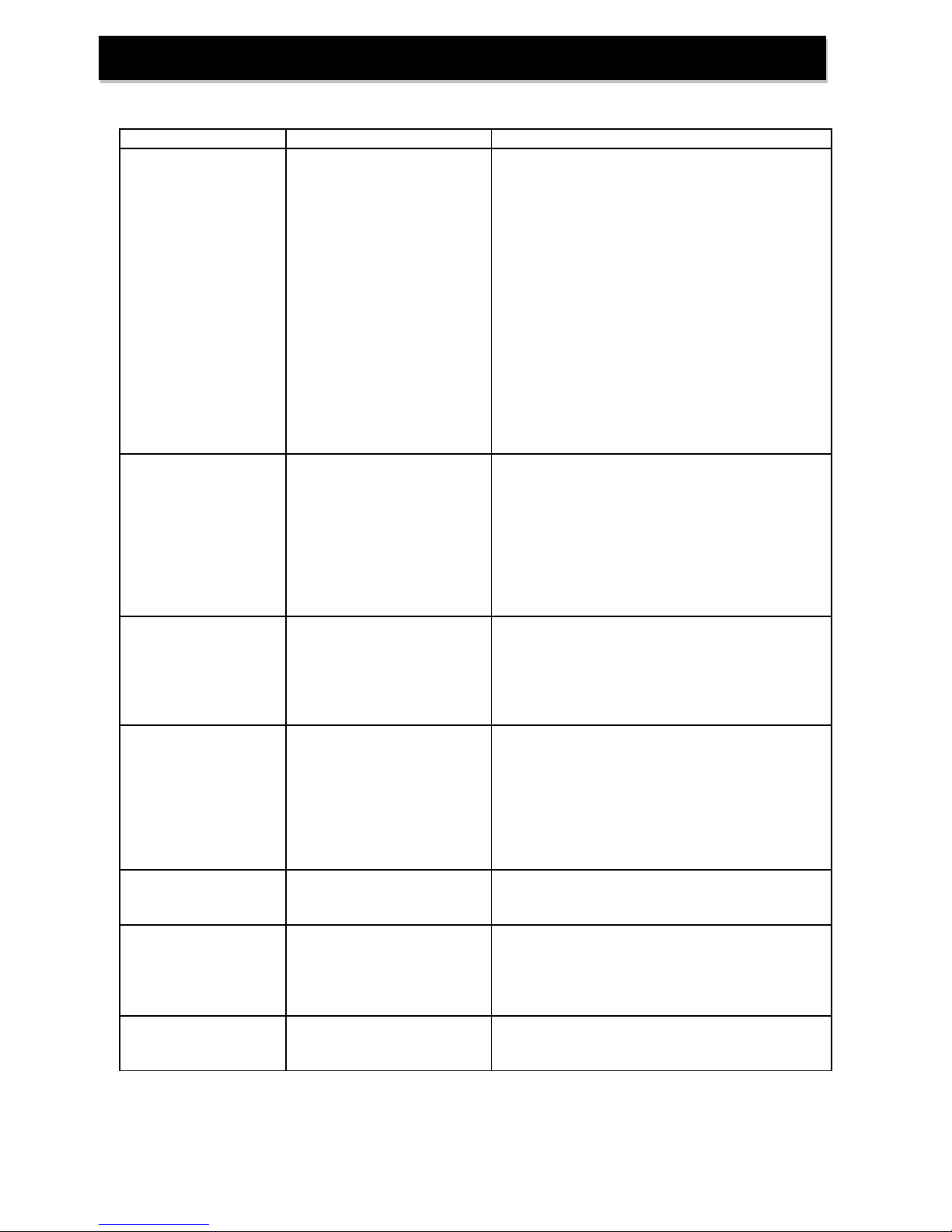
PROBLEM
CAUSES
SOLUTIONS
Excessive pressure
drop through filter
A) Filter not
backwashing
B) Filter bed loaded
with sand
C) “Cementing” or
“Channeling”
D) Drain line restricted
E) Top Screen Fouled
F) Control Valve
plugged with debris
1) Check timer motor and replace if faulty
2) Ensure uninterrupted power supply
3) Check Backwash frequency setup
4) Verify sediment being removed is less
dense than the filter media and install a
“Spin-Down” type sediment filter ahead
of the FBW to remove well sand
5) Verify adequate pumping rate for
backwash
6) Probe media bed to check for
“Cementing”
7) Check drain line for restriction: frozen,
plugged, kinked, exceeds 15’, overhead
installation, flexible drain line, drain line
diameter too small
8) Remove and clean top screen
9) Disassemble and clean control valve
Contaminant not being
properly removed
A) Leaking bypass
valve
B) Internal valve leak
C) Distributor not
seated properly in
control valve
D) Water usage flow
rate exceeds filter
specifications
1) Verify bypass valve is in service position
2) Replace piston, spacers and seals
3) Verify distributor tube seated securely in
control valve body
4) Verify actual water usage flow rates
against system specifications
5) Increase length of backwash and rinse
cycles
Neutralizer media
raises pH too high
A) Filter is brand new
B) Wrong media used
1) Turn bypass valve very slightly to the
“Bypass” position allowing a small
amount of untreated water to bleed into
the treated water
2) Rebed the unit with a less aggressive
media
Neutralizer media fails
to raise pH sufficiently
A) Water usage flow
rate is too high to
provide adequate
contact time
B) Media bed is
“Cemented” or
“Channeled”
1) Verify actual water usage flow rates
against system specifications
2) Verify adequate pumping rate for
backwash
3) Check drain line for restriction: frozen,
plugged, kinked, exceeds 15’, overhead
installation, flexible drain line, drain line
diameter too small
Birm Filter fails to
remove iron
A) pH too low
B) Dissolved oxygen
level too low
1) pH of untreated water must be 6.8 or
higher – adjust with proper equipment
2) Aerator may be installed prior to the filter
Loss of media
to drain
A) Air in system
B) Insufficient soak
time before first
backwash after
installing media
1) Ensure well system has proper air
elimination control
2) Check media level and adjust if
necessary
Howling or whistling
noise during
regeneration
A) Inadequate drain
line diameter or
drain line restricted
1) Reconfigure or replace drain line
Troubleshooting
17
Page 19
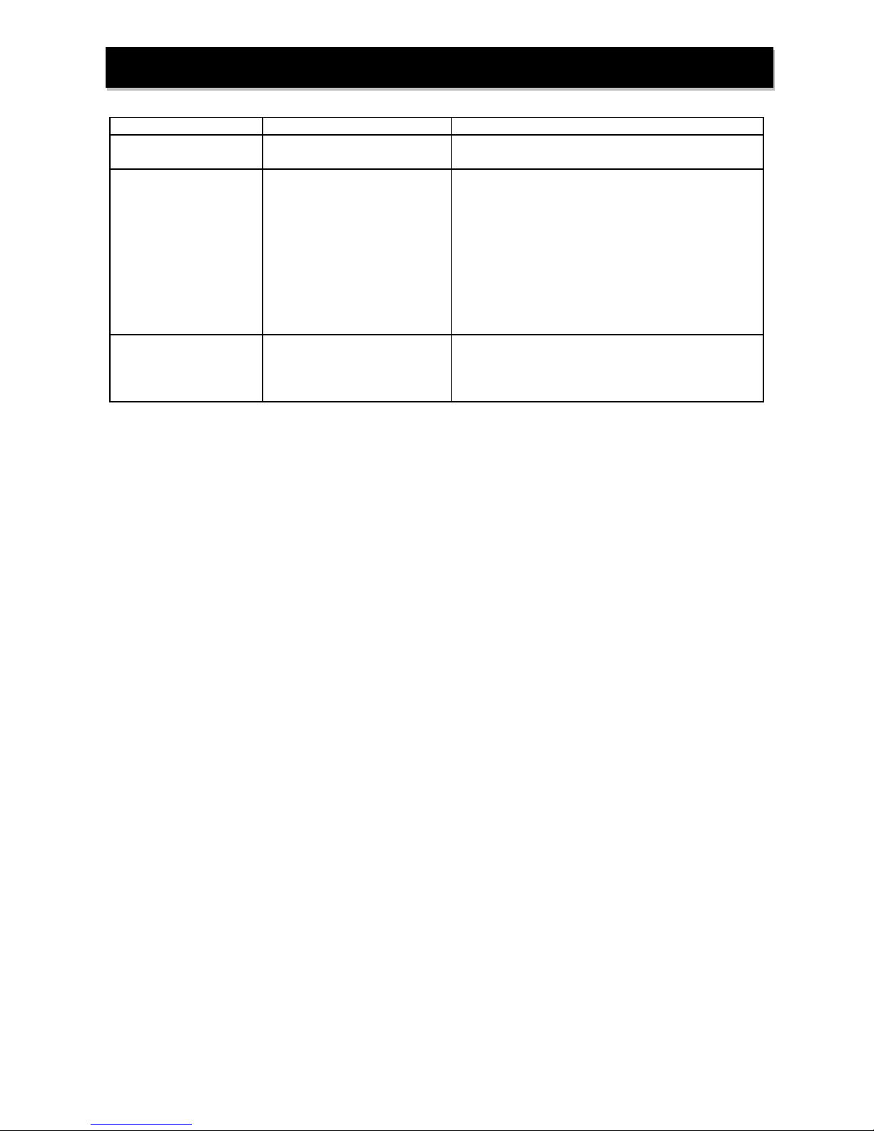
PROBLEM
CAUSES
SOLUTIONS
Control Valve
cycles continually
A) Faulty switch
B) Faulty timer motor
1) Replace faulty switch
2) Replace faulty timer motor
Continuous flow of
water to drain
A) Loss of electrical
power during
regeneration
B) Program wheel
setup incorrectly
C) Debris in control
valve
D) Internal leak in
control valve
E) Drive motor faulty
1) Ensure electrical outlet is functioning
2) Verify timer programming
3) Disassemble and clean control valve
4) Replace seals and/or piston
5) Replace faulty drive motor
Media in the
service lines
A) Unit installed
backwards
1) Re-plumb the water lines so that the
supply side of the line is connected to the
inlet of the bypass and the service side is
connected to the outlet.
Troubleshooting
18
Page 20
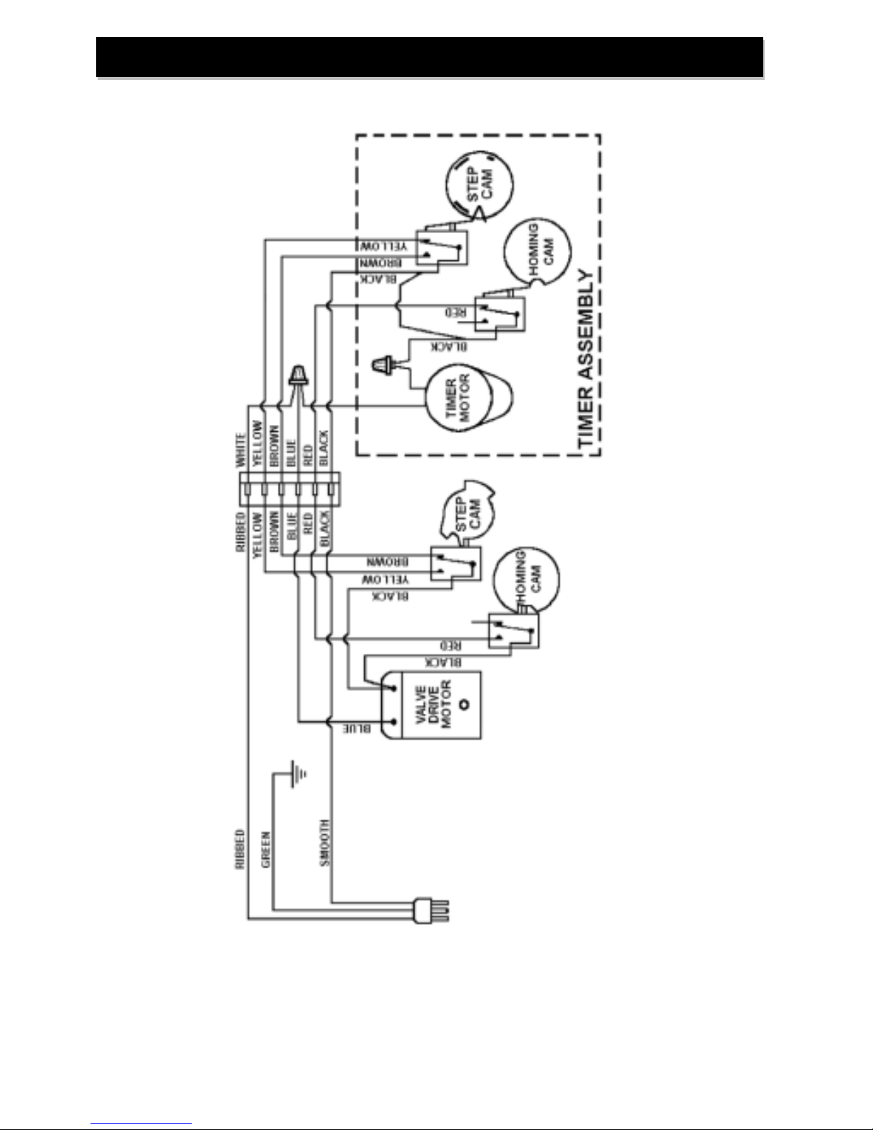
Control Valve Wiring Diagram
19
Page 21
20
 Loading...