

Page 1
COACT
MEDIA UNIT ASSEMBLY WITH X9 OPEN SHELF STORAGE OPTION
INSTALLATION INSTRUCTIONS
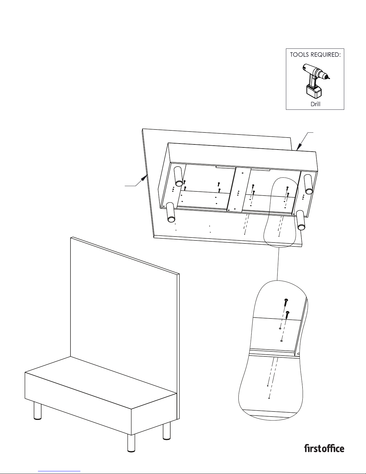
1. Begin by placing the back panel on a flat non-marring surface, making sure the
pre-drilled holes are facing up. Next, position the box platform onto the back
panel by aligning the mounting holes with the pre-drilled holes on the back panel.
2. Using the screws from the HK-104 kit, fasten the box platform to the back panel,
making sure the bottom edges are flush and that the box platform is centered,
as shown above. If neccessary, loosen the screws slightly, adjust the location, and
re-tighten the screws.
BACK PANEL
PART # 1609103
BOX
PLATFORM
Page 2
COACT
MEDIA UNIT ASSEMBLY WITH H4R/H4Q OPEN SHELF STORAGE OPTION
INSTALLATION INSTRUCTIONS
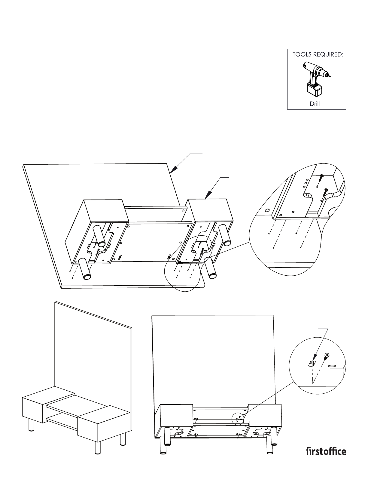
1. Begin by placing the back panel on a flat non-marring surface, making sure
the pre-drilled holes are facing up. Next, position the box platform onto the
back panel by aligning the mounting holes with the pre-drilled holes on the
back panel.
2. Using the screws from the HK-104 kit, fasten the box platform to the back
panel, making sure the bottom edges are flush and that the box platform is
centered, as shown above. If neccessary, loosen the screws slightly, adjust the
location, and re-tighten the screws.
3. With the box platform fastened, the shelves can now be secured to the back
panel by fastening the screws from the HK-15 kit into the pocket bores as
shown below.
BACK PANEL
BOX PLATFORM
PART # 1609104
POCKET BORE
Page 3
COACT
WIRE MANAGER INCLUDED WITH H4Q
INSTALLATION INSTRUCTIONS
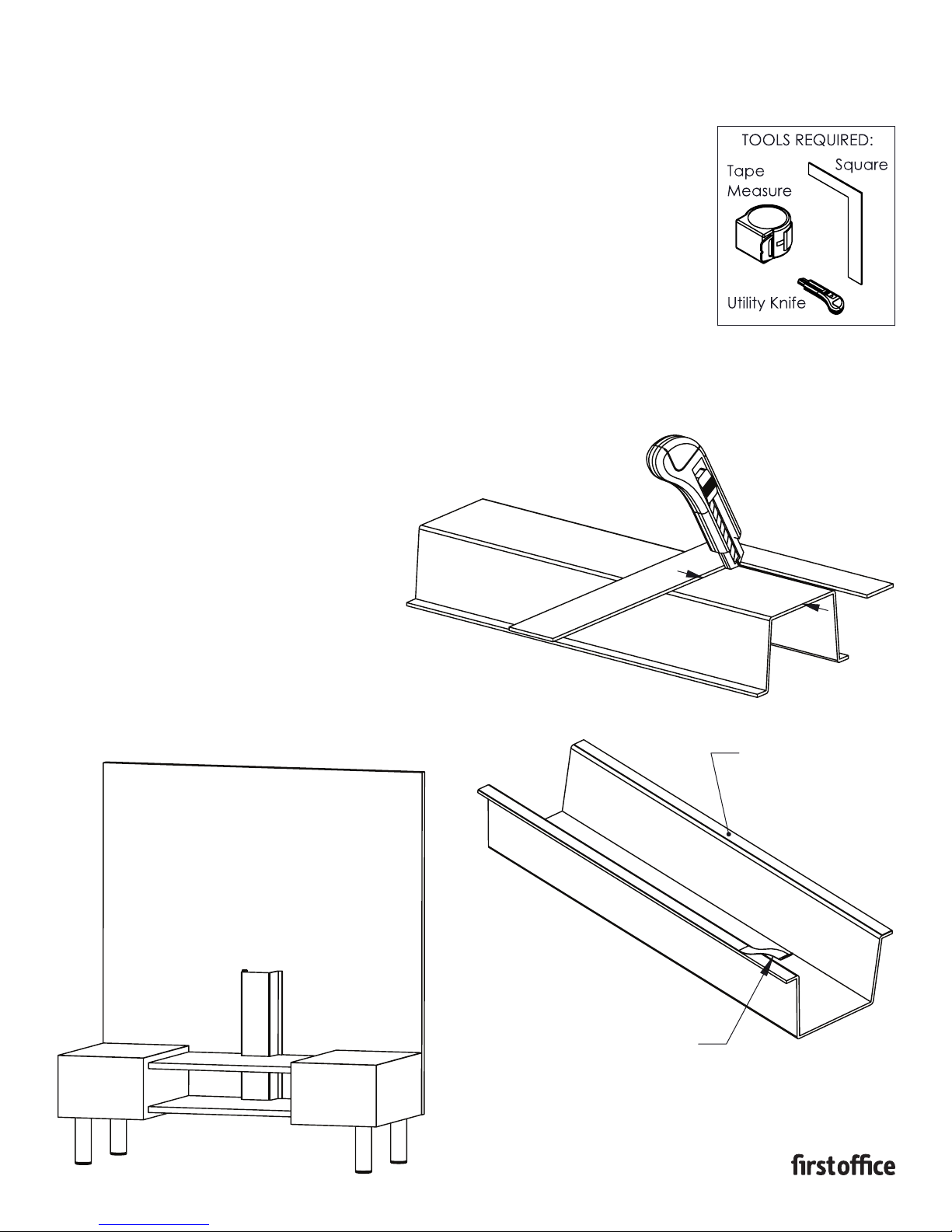
NOTE: Depending on how your Media Unit is being utilized, it could require
cutting the Wire Manager to the appropriate length.
1. If it is necessary to cut the Wire Manager, measure to the desired length, and using
a square and utility knife, score the Wire Manager multiple times along the top face.
Once scored, cut completely through. Repeat this step for the remaining faces.
2. With the Wire Manager cut to the correct length, peel back the paper wrapper on the
back side to expose the adhesive, as shown above. Place the Wire Manager onto the
back panel of the Media Unit, making sure it is centered and covering the grommet
opening on the shelf. Press firmly on the flanges to ensure a good contact.
PART # 1609105
CUT LENGTH
ADHESIVE BACKED
FLANGE
WRAPPER
Page 4
COACT
CORNER MEDIA UNIT
INSTALLATION INSTRUCTIONS
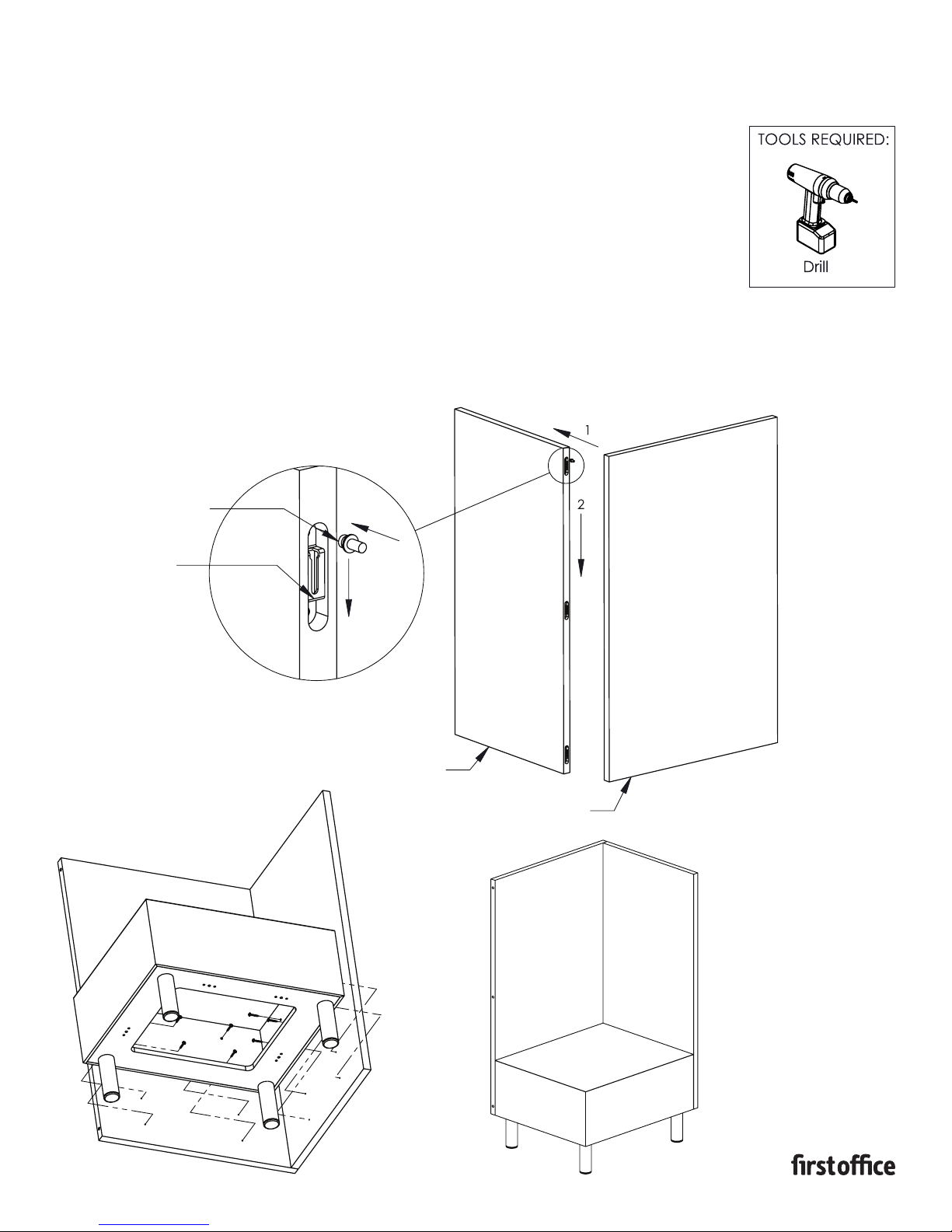
1. Begin by assembling the “L” shape back panel as illustrated in the upper most view.
Place the back panel onto the end panel, making sure the shoulder screw is inserted
into the pocket on the end panel and above the slot opening of the mod-eez clip as
shown in the detail view above. When the screw and clip are engaged, gently tap the
back panel down until both panels are flush with each other.
NOTE: The panel will fit tighter the farther it travels downward. If neccessary, use a rubber
mallet, or loosen the shoulder screws 1/4 turn to ease the panel attachment.
2. Next, position the box platform onto the assembled back
panel by aligning the mounting holes with the pre-drilled holes on the assembled back
panel. Using the screws from the HK-104 kit, fasten the box platform to the assembled
back panel, making sure the box platform is flush, or just inside of the assembled back
panel, as shown above. If neccessary, loosen the screws slightly, adjust the location, and
re-tighten the screws.
SHOULDER
SCREW
PART # 1609106
MOD-EEZ
CLIP
END PANEL
BACK PANEL
Page 5
COACT
RUNOFF TABLE INSTALLATION
INSTALLATION INSTRUCTIONS
NOTE: It is recommended to install the Runoff Table after the Media Unit
has been placed in its final resting position.
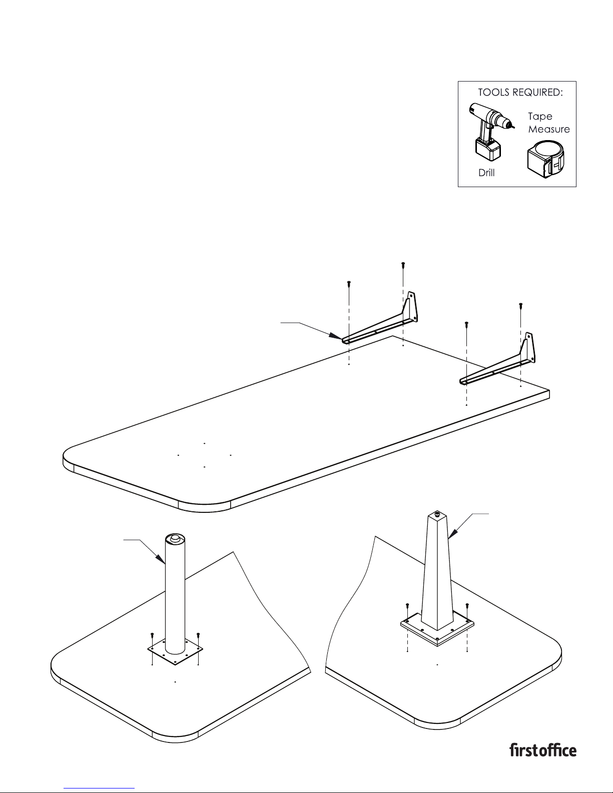
1. Begin by placing the worksurface on a flat non-marring surface, making sure the predrilled holes are facing up. Next, place the worksurface brackets onto the worksurface
and align the mounting holes to the pre-drilled holes. Fasten the brackets down using
the supplied screws from the HK-125 kit, making sure every mount hole is utilized.
2. Next, place the table base onto the worksurface. Depending on which base style was
chosen, two of the four pre-drilled holes on the worksurface will align with the mount
holes on the base mount plate, as shown above. Fasten the base down using the
screws supplied with the base, making sure every mount hole is utilized.
WORKSURFACE
BRACKET
PART # 1609107
SHEET 1
METAL BASE
Continue to next page
WOOD BASE
Page 6
RUNOFF TABLE INSTALLATION CONTINUED
INSTALLATION INSTRUCTIONS
NOTE: It is recommended to install the Runoff Table after
the Media Unit has been placed in its final resting position.
PART # 1609107
SHEET 2
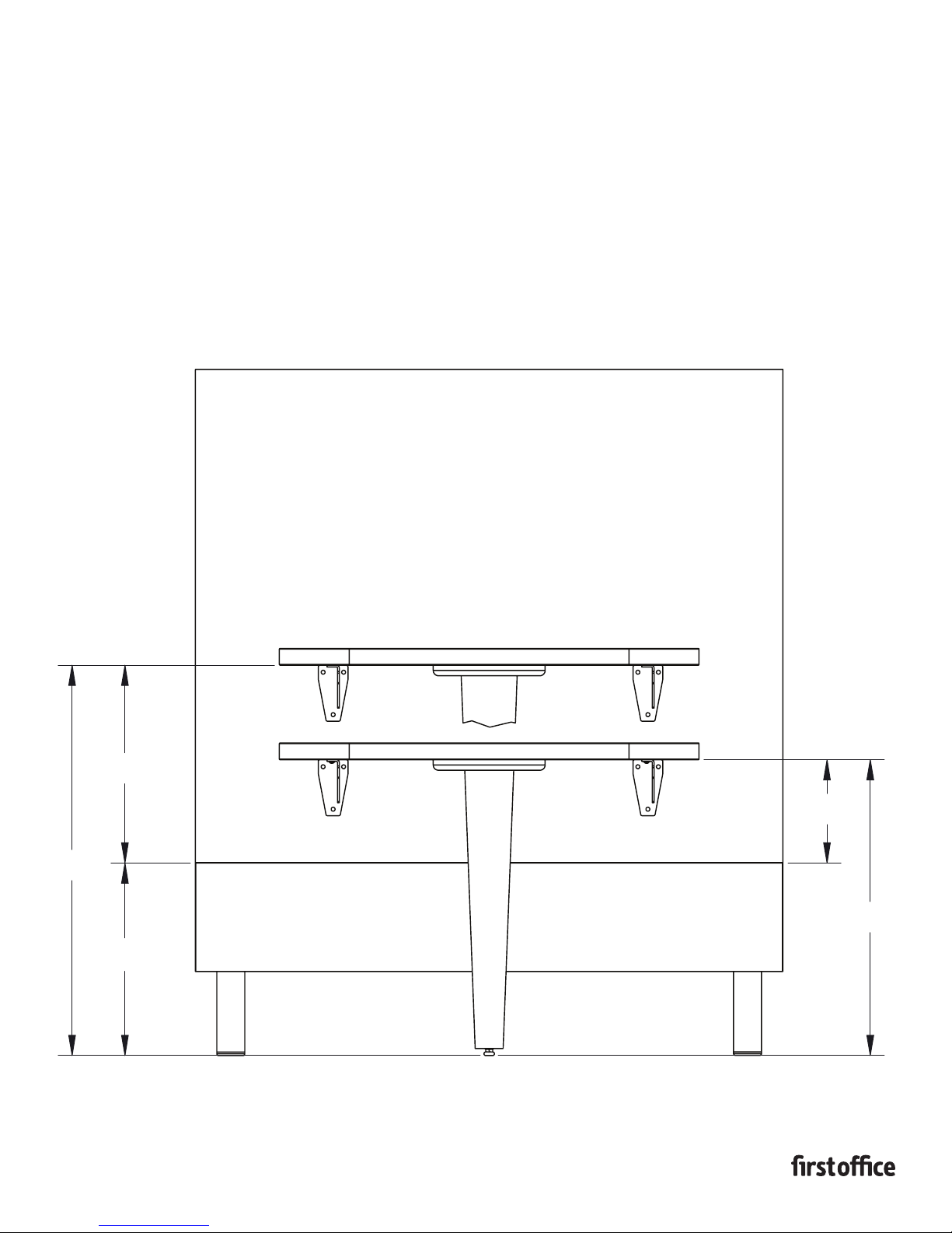
3. Using the view above, measure the distance required for
your Runo table height and scribe a temporary line to mark
the location for the bottom of the worksurface. This can be
done by measuring from the floor, or from the top of the
box platform (Verify that box platform height is 13-3/4", as
shown above).
4. Making sure the worksurface is centered with the Media Unit
and the bottom edge aligns with the scribed line, fasten the
Runo table to the back panel of the media unit using the
remaining screws from the HK-125 kit.
14 1/8"
7
27
/8"
3
13
/4"
3
7
/8"
1
/8"
21
Page 7
COACT
MEDIA UNIT GANGING CONNECTION
INSTALLATION INSTRUCTIONS
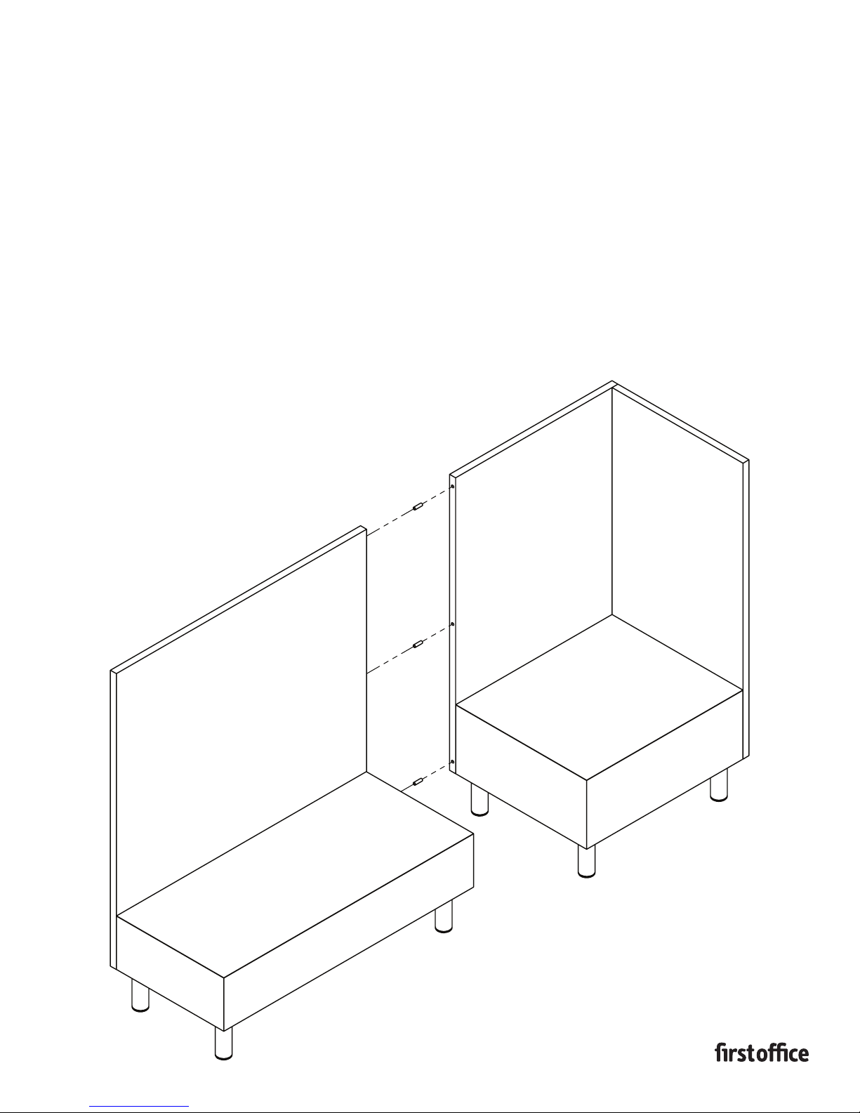
1. Starting with one of the Media Units, insert the dowel pins from the HK-126
kit halfway into the bored holes on the back panel, as shown above.
2. Next, slide the adjoining Media Unit against the connecting Media Unit,
making sure the dowel is inserted into the aligning hole. Refer to the
“Ganging Bracket” installation sheet to complete the “Lounge Ganging
option” installation of the Media Units.
PART # 1609108
 Loading...