

Page 1
))) FirstLook
®
DIAGNOSTIC PULSE SENSORS
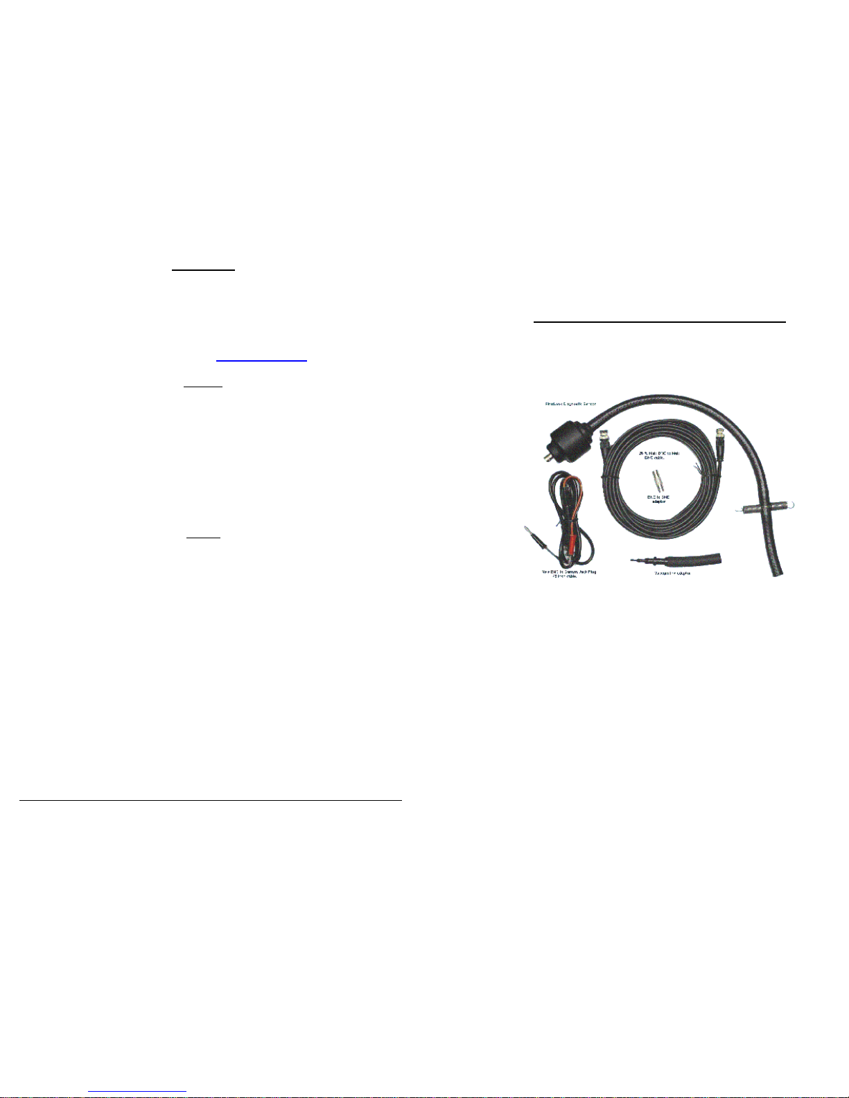
Automotive Diagnostic Sensor
Model ADS ES 100
Quick Setup Guide
SenX Technology LLC
5315 Sunset Drive
Midland, MI 48640
Phone 866-832-8898
Fax 989-832-8908
FirstLook
®
is a trademark of SenX Technology, LLC
SenX
®
is a trademark of SenX Technology, LLC
U.S. Patent No. 6,484,589
Made in the U.S.A.
Version 3.5
Support
For support questions or warranty assistance contact:
SenX Technology, LLC
5315 Sunset Drive
Midland, MI 48640
Phone 989-832-8898 Fax 989-832-8908
Or visit our web site at http://senxtech.com
Warranty
SenX Technology, LLC warranties the products described herein for a period of 1year under
normal use and service from the date of purchase that the product will be free of defects in
material and workmanship. This warranty does not cover ordinary wear and tear, abuse,
misuse, overloading, altered products, or damage caused by the purchaser connecting the unit
incorrectly.
THERE IS NO WARRANTY OF MERCHANTABILITY. THERE ARE NO WARRANTIES WHICH EXTEND
BEYOND THE DESCRIPTION HEREIN. THERE ARE NO WARRANTIES EXPRESSED OR IMPLIED OR
ANY AFFIRMATION OF FACT OR REPRESENTATION EXCEPT AS SET FORTH HEREIN.
REMEDY
The sole responsibility and liability of SenX Technology, LLC, and purchaser's exclusive remedy
shall be limited to the repair or replacement at SenX Technology’s option, of a part or parts
not conforming to the warranty. All products requiring warranty service shall be returned to
SenX Technology within 1 year of purchase, shipping prepaid. SenX Technology will return
repaired or replaced products to the purchaser via prepaid ground transportation. In no event
shall SenX Technology be liable for damages of any nature, including incidental or
consequential damages, including but not limited to any damages resulting from nonconformity, defect in material or workmanship.
Neither SenX Technology LLC nor its affiliates shall be liable to the purchaser of this product or
third parties for damages, losses, costs, or expenses incurred by the purchaser or third parties
as a result of: accident, misuse, or abuse of this product or unauthorized modifications,
repairs. or alterations to this product, or failure to strictly comply with SenX Technology's
operating and maintenance instructions.
No part of this publication may be reproduced, stored in a retrieval system, or transmitted in
any form or by any means, electronic, mechanical, photocopying, recording, or otherwise,
without the prior written permission of SenX Technology, LLC.
FirstLook® and SenX® Technology are trademarks of SenX Technology, LLC
8
Page 2
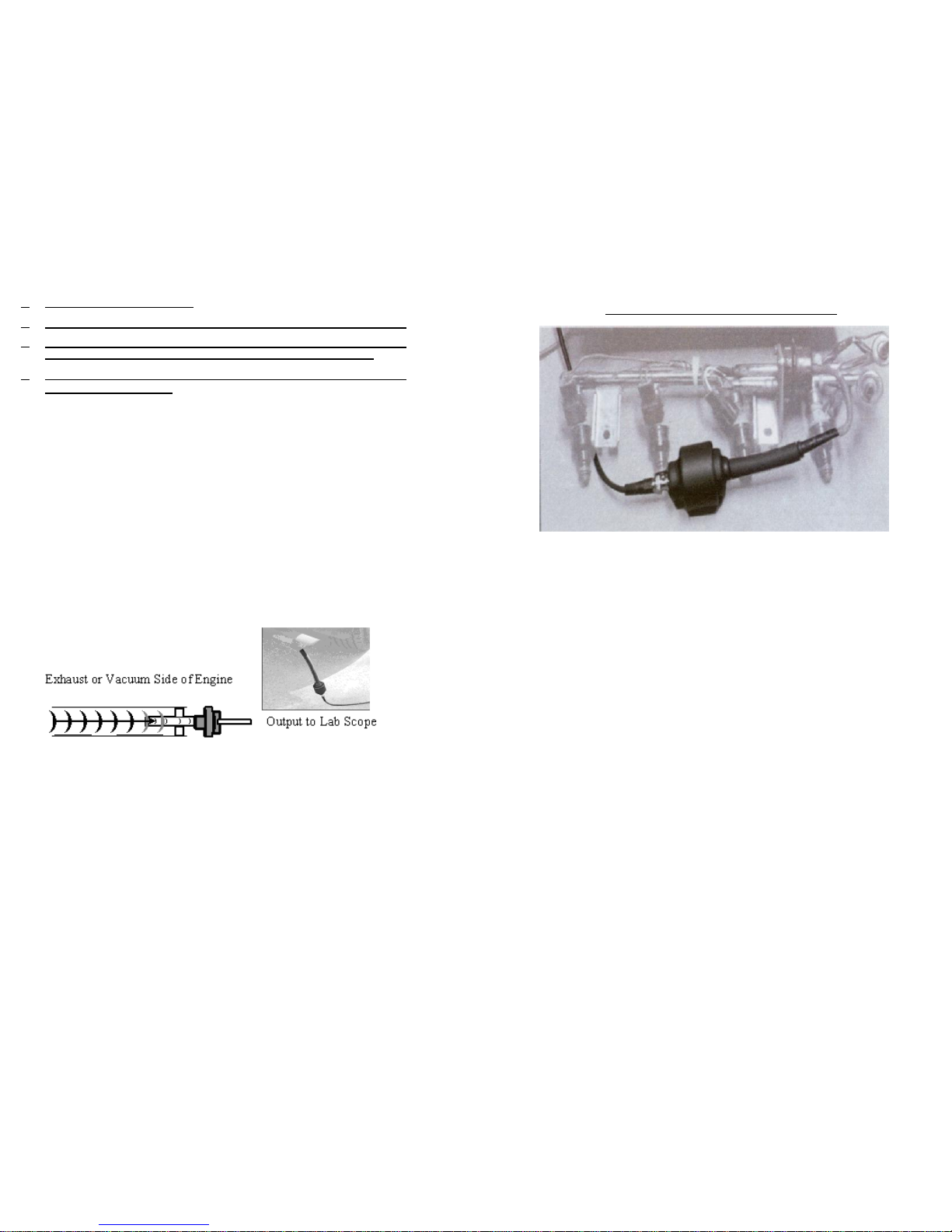
FAST AND EASY HOOK UP
LOCATE PROBLEM CYLINDERS THRU EXHAUST SYSTEM PULSES.
COLD CRANK ENGINE TEST DETERMINES CORE ENGINE
PROBLEMS- VALVE LEAKAGE, CYLINDER COMPRESSION.
HOOK UP TO FUEL PRESSURE REGULATOR AND CHECK FOR
INJECTOR PROBLEMS.
Theory of Operation
The FirstLook Diagnostic Sensor is unique because it looks at
pulses in engine airflow, allowing you to display "the pulse of
your engine" on standard scope equipment. While scanners
interrupt the information they receive from engine sensors and
engine analyzers tell us what the ignition system is doing, it is
difficult to see what was actually happening in the engine
without intrusive tests. With the FirstLook Diagnostic Sensor in
your diagnostic arsenal it will now be possible to see what is
dynamically occurring in your engine.
Pulses vary over time depending upon the stroke cycle of engine
It is important to try out your FirstLook Diagnostic Sensor on a
good engine to understand what is normal. Cause a basic
problem by disabling a plug or injector and see the effects on
the waveform. What you are looking for is a consistent
pattern, do not try and diagnose every little bump in the
waveform. It is the major deviations from normal that you
need to address.
2
Fuel Injector Pressure Regulator Test
1. This is one of the fastest ways to see if there is a volume difference
between any of the injectors.
2. Just remove the vacuum line from the fuel pressure regulator
and plug it. Now hook up the impulse sensor to the fuel pressure
regulator nipple.
3. Trigger the scope on #1 injector. There is no off set to think about
here. They will show up in the correct fire order.
4. Set the trace up with the pulse sensor to either lv or 2v ac scale,
time is consistent with all other tests. Idle 200 ms, 1500 RPM
power brake test 100ms.
5. As the injector pintles open and close, the sensor reads the
pressure drop that the fuel pressure regulator diaphragm creates.
6. All that is left is to see is which injector amplitude is higher (more
fuel) or lower (less fuel).
7. As with all of the tests mentioned it is very important to practice on
known good cars and create certain conditions to see how they
compare.
7
Page 3
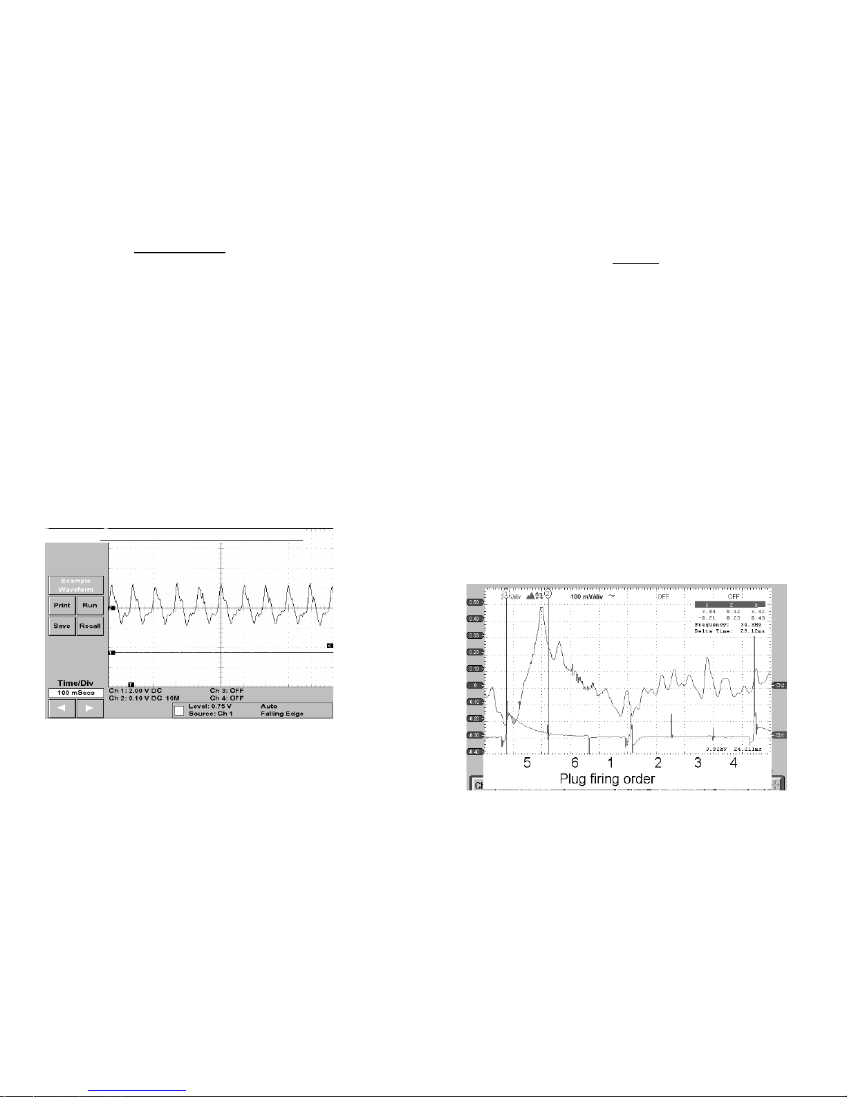
Cold Crank 97 Chrysler Intrepid 85000 Miles
A
6
Cold Crank Test
This is the single most important test you can run. Knowing
the basic condition of an engine can save you many hours of
work and get you to the actual problem much faster.
Starting Scope settings
1. Depending on cranking RPM time base will be .5 second to
1 second. sweep of scope screen.
2. Set scope to AC signal.
3. Starting voltage range .5 + or -.
4. Disable fuel pump or in the case of carbureted engine
disable spark.
5. Insert black end of hose with springs about 5 to 8 inches into
tail pipe.
6. Crank Engine to determine best voltage setting.
7. Once you have determined best setting crank engine and
freeze the screen to examine the pattern.
This waveform shows a typical high mileage engine. The engine is
in good shape with a small amount of valve leakage. Small
irregularities can indicate dirty or worn valves. Major problems
will show up as major fluctuations in the scope pattern. This is a
quick simple test to determine basic engine condition. Once you
determine that you have a major problem you can now proceed
to concentrate your resources in that area.
Idle Test
This test allows a mechanic to identify a problem that is specific to a
particular cylinder using a trigger signal. It also allows you to look for
intermittent problems more easily because you are actually watching
the engine running in real time.
Starting Scope Settings
1. Idle test… 650 to 700 RPM…Scope settings.
2. Set Scope to AC signal
3. Voltage settings… +1 Volts to – 1 Volts
4. Time base … 200 ms
5. Insert black end of hose with springs about 5 to 8 inches into tail pipe.
8. Start Engine and adjust voltage for best display of waveform.
9. Start Engine and allow idle to stabilize.
10. Freeze the screen to examine the pattern.
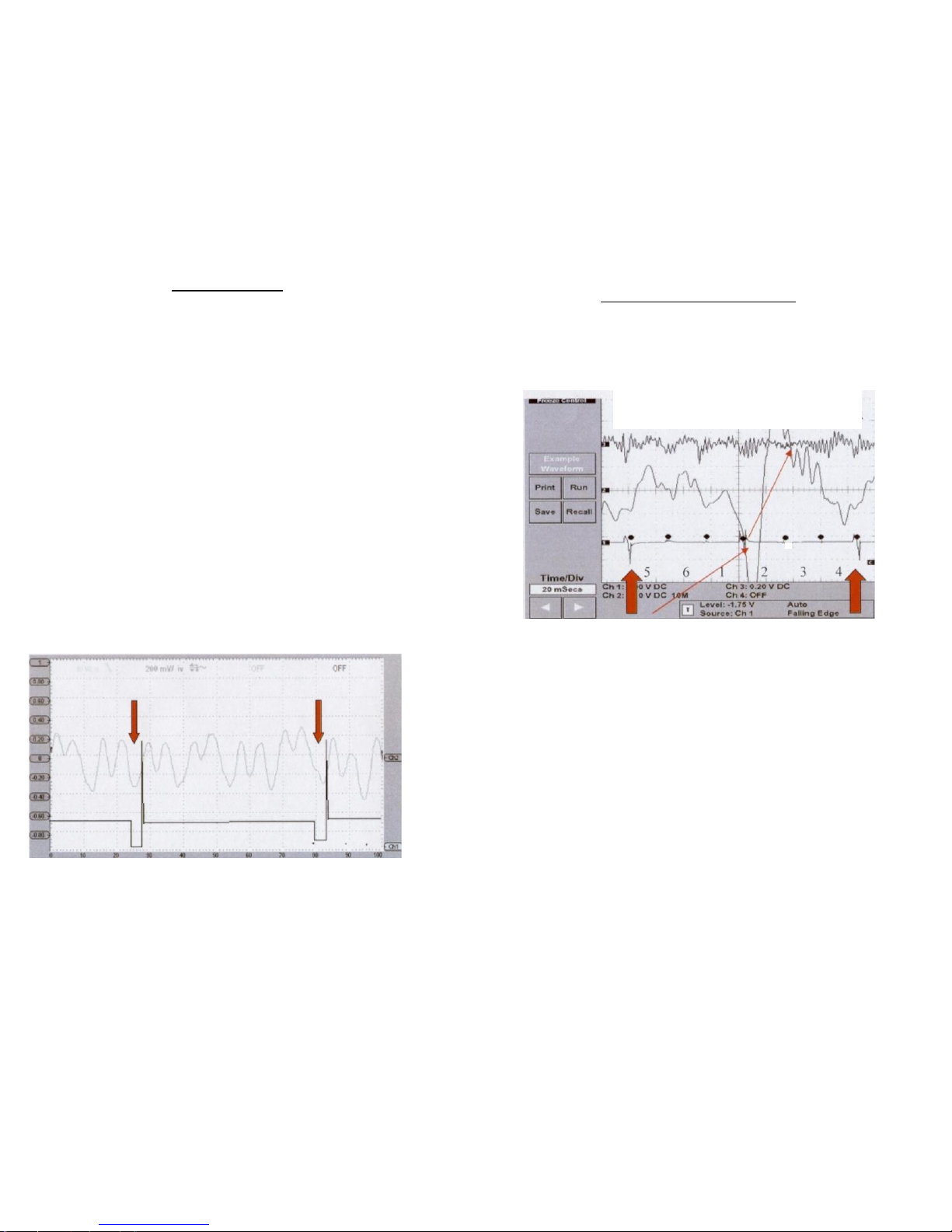
11. This test was run using #1 plug as trigger reference
2001 Chevrolet Impala 6 cylinder Engine
Firing Order 1-2-3-4-5-6
Remember cylinder offset
#5 Cylinder misfire
It is important that if you have multiple problems to solve each
problem in order and rerun the test to determine the next problem.
3
Page 4
Injector s equence from Plug reference
As soon as valve closes injector fires. This means
injectors are 1 step to right of exhaust sequence.
4 5 6 1 2 3 4
•
Power Brake Test.
This test is used to determine problems of engine under a
simulated load. It is best to use 2 people to do this test, one
person to operate the car and the other person to run the scope.
Starting Scope Settings
1. Set Scope to AC signal
2. Voltage settings... +1 Volts to — 1 Volts
3. Time base ... 200 ms
4. Start engine and adjust voltage for best display of waveform.
5. Put engine into gear and set brakes.
6. Slowly accelerate engine to 1500 RPM.
7. Freeze the screen to examine the pattern.
8. Return engine to idle and put in Neutral.
9. This test was run using #1 plug as trigger reference. The Cold
Crank test can be run with or without a trigger as a quick
reference to the basic condition of the engine. Using a hand
held scope it is easy to walk out the door and take a quick look
at an engine.
Red Arrows indicate #1 Plug Trigger
97 Honda Accord Power Brake
4
How do you find the #1 cylinder?
Tail pipe readings are offset from the trigger reference. This accounts for
the time elapsed between from ignition firing and exhaust valve opening.
You need to understand offset to properly locate a problem cylinder.
PONT IAC 3800
#2
INJEC TOR DIS ABLE D EX HAUST AT IDLE
Vertical arrows indicate inductive trigger using cylinder #1 as reference.
This screen shot shows both the injectors and the exhaust at idle.
Firing order 1-2-3-4-5-6...Offset 5-6-1-2-3-4.
1. Tail pipe readings are offset from the trigger reference. This
accounts for time from ignition firing to exhaust valve opening.
2. From the start of your trigger point, offset the cylinders like this
3. 4 cylinder engines offset 1 pulse to the right.
4. 6 cylinder engines offset 2 pulses to the right
5. 8 cylinder engines offset 3 pulses to the right
6. This Pontiac fire order is 1-2-3-4-5-6
7. But with the offset it is read on the scope as 5-6-1-2-3-4
8. To determine timing between exhaust or injector events
refer to the timing chart included with your FirstLook
Diagnostic Sensor.
5
 Loading...