

Page 1
Data Controller (DC)
Remote Start for Mercedes
www.compustar.com
888.820.3690
2006 - 2009 ML, GL, and R Class
FT-MB164-DC Installation Guide
Welcome to the installation guide for the 2006 to 2009 ML, GL, and R Class Mercedes Benz. Please
thoroughly review this manual before installation as there are details that are essential to operation of
the vehicle. Please don’t forget to review the installation manual included with the DC unit.
This manual is intended for experienced installers. Firstech recommends professional installation as
we are not responsible for improper use and/or installation. For questions please call 888-820-3690
Monday through Friday 8 am to 5 pm PST.
Required Parts and Tools
T-20 Torx Driver•
Panel Removal Tool•
Drill•
3/4” Drill Bit•
DC Control Module
Copyright 2010 Firstech, LLC. | 1
Page 2

Data Controller (DC)
Remote Start for Mercedes
www.compustar.com
888.820.3690
2006 - 2009 ML, GL, and R Class
FT-MB164-DC Installation Guide
Instructions
1. Remove the HVAC panel by pulling outward to release the lower clips. (pic 1)
2. Pull down on the panel to release the upper clips. (pic 2)
3. Remove the panel and place it to the left being careful not to scratch the console or the wood
grain front. For an R class, (pic 3) insert a panel tool on the left and right upper edges of the
HVAC panel and release the clips, then remove the panel by pulling out the top first then
pulling up on the entire panel to release the lower clips.
4. Locate and remove (2) T-20 screws from the aluminum bars showing just below the radio.
(pic 4)
5. Slide the bars downward until they stop. These are the radio retaining bars. (pic 5)
6. Slide the COMAND unit out from the dash to access the wiring behind. (pic 6)
7. Disconnect all wiring from the rear of the COMAND unit and place it in a safe place where it
cannot be damaged while you’re working on the vehicle.
8. Let the vehicle sit for 2 minutes with the doors open to allow the CAN network to shut
completely down before going any further.
9. Reach through the radio cavity and locate the rear of the EIS module. The EIS is the key
switch.
10. Release (2) connectors from the EIS and pull the harness out through the radio opening for
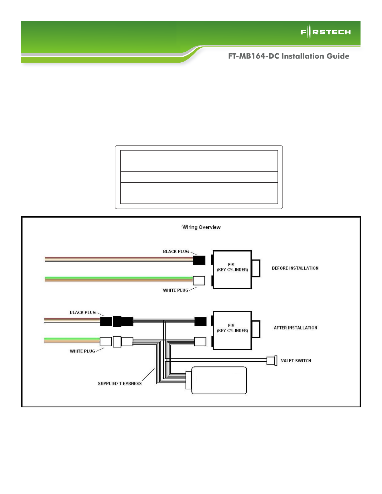
easy access. It is important that you disconnect the lower (black) plug first. (pic 7)
11. Make sure the Valet switch is off or disconnected. (pic 8)
12. Plug the (2) male ends from the T-Harness that match the plugs you just
removed into the rear of the EIS module. (pic 9)
13. Plug the connectors into the Mercedes DC control module.
14. Plug the (2) female connectors from the control module into the factory wiring you
accessed in step 9. It is important that you plug the white connector in first. (pic 10)
15. Once ALL connections are secured, turn on the valet switch and verify the LEDs visible inside
the Mercedes DC are flashing.
16. Start the vehicle with the key or with the push button to verify your work. If the vehicle starts
and runs, you’ve made all the connections correctly.
17. Shut the vehicle off.
18. Push the ‘Panic’ button once on the factory remote to test the remote start.
19. Once you are satisfied with its operation, shut the remote start off by pushing the
‘Panic’ button once.
20. Unlock the vehicle with the remote after shutdown
21. Locate a place to secure the control module in the dash cavity.
22. Secure the module in its final location.
23. Locate a place for the valet override switch. Recommended locations are the left wall of the
glove compartment or the driver’s underdash panel.
24. Drill a 3/4” hole in the desired location.
25. Route the wires for the valet switch through hole for the control module.
26. Plug the Valet switch in. Make sure the spade connectors are fully installed on the switch.
Copyright 2010 Firstech, LLC. | 2
Page 3

Data Controller (DC)
Remote Start for Mercedes
2006 - 2009 ML, GL, and R Class
FT-MB164-DC Installation Guide
27. Reinstall the COMAND by first plugging in all harnesses and antenna connections that you
removed in step 7.
28. Slide the COMAND back into its opening.
29. Push up on the radio retaining bars to secure the radio.
30. Reinstall the (2) T-20 screws to secure the radio retention bars.
31. Confirm the proper operation of the COMAND unit.
32. Reinstall the HVAC panel by inserting the top edge of the panel just below the face of the
COMAND unit.
33. Push the bottom edge of the HVAC panel toward the dash.
34. Pull downward to confirm its proper location. If done properly, the upper edge will catch on its
retainer and will not allow it to move downward.
35. Align the opening in the HVAC panel with the slide out drawer at the bottom and provide gentle
pressure to snap the bottom edge into place.
Installation Images
1) Pull out on bottom of HVAC panel 2) Pull down on HVAC panel
Insert panel tool here, one side at a time
3) R class panel removal 4) Remove T-20 screws
Copyright 2010 Firstech, LLC. | 3
Page 4

Data Controller (DC)
Remote Start for Mercedes
2006 - 2009 ML, GL, and R Class
5) Pull down on retaining bars 6) Remove and disconnect COMAND unit
www.compustar.com
888.820.3690
FT-MB164-DC Installation Guide
7) Access EIS wiring through opening 8) Make sure the valet switch is off
Factory EIS wiring
External view of EIS module
Starter T-Harness
9) Plug the harness into the rear of the EIS 10) Connect the factory wires to the T-Harness
Copyright 2010 Firstech, LLC. | 4
Page 5

Data Controller (DC)
Remote Start for Mercedes
2006 - 2009 ML, GL, and R Class
FT-MB164-DC Installation Guide
Installation Complete
Firstech, LLC. is not responsible for any damages whatsoever, including but not limited to any consequential
damages, incidental damages, damages for loss of time, loss of earnings, commercial loss, loss of economic
opportunity and the like that may or may not have resulted from the installation or operation of the Data
Controller for Mercedes.
Copyright 2010 Firstech, LLC. | 5
 Loading...