

Page 1

U.S. Patent No. 8,856,780
20170808
REVISION DATE
FT-RSD-VW7-[FT-DC3-HC]
FIRMWARE
FT-DC3-HC
HARDWARE
ADS-USB (OPTIONAL)
ADS-WLM-AN1/ADS-WLM-AP1 (OPTIONAL)
DRONE MOBILE DR-2000 (OPTIONAL)
COMPATIBLE RF-KIT (OPTIONAL)
ACCESSORIES
DOCUMENT NUMBER
2015-2017 AUDI A3 PTS AT
www.idatalink.comAutomotive Data Solutions Inc. © 2017
INSTALL GUIDE
NOTICE
The manufacturer will accept no responsability for any electrical damage resulting from
improper installation of this product, be that either damage to the vehicle itself or to the
installed device. This device must be installed by a certified technician. Please review the
Installation Guide carefully before beginning any work.
Page 2

T002_H
T-HARNESS / COMPONENT LOCATOR - 1 OF 1
B
C
D
A
PAGE 2 OF 9
U.S. Patent No. 8,856,780 2015-2017 Audi A3 PTS AT
www.idatalink.comAutomotive Data Solutions Inc. © 2017 FTRSDVW7FTDC3HCEN
20170808
Page 3

!
CUT LOOP FOR AUTOMATIC TRANSMISSION ONLYCUT LOOP FOR AUTOMATIC TRANSMISSION ONLY
1
2
SOME PARTS OF THE T-HARNESS (VS5/VS6, VS7/VS8, VS9/VS10 AND JS9) ARE NOT USED IN THIS INSTALL
DO NOT CONNECT THEM.
SOME PARTS OF THE T-HARNESS (VS5/VS6, VS7/VS8, VS9/VS10 AND JS9) ARE NOT USED IN THIS INSTALL
DO NOT CONNECT THEM.
TWO KEYS ARE REQUIRED FOR THIS INSTALLATION.
ONE KEY WILL REMAIN PERMANENTLY IN THE
VEHICLE. THE OTHER KEY WILL BE USED FOR THE
PROGRAMMING PROCEDURE. IT WILL THEN BE
RETURNED TO THE OWNER.
12V (+) RED/BLUE - 73
HORN (-)
3
3
T002_H
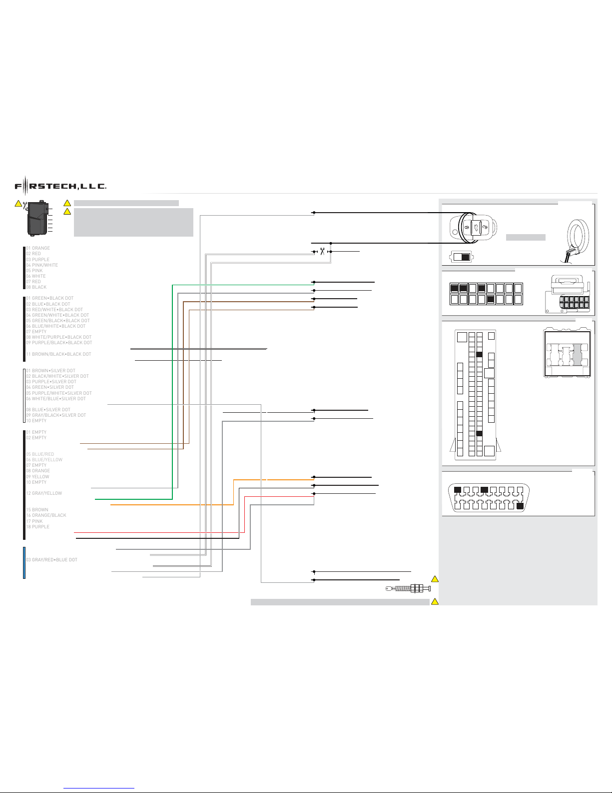
T-HARNESS / WIRING DIAGRAM - 1 OF 1
M5
M4
M2
M3
OBDII (A)
HAZARDS (-) PURPLE/RED - 42
BRAKE (+) BLACK/RED - 58
HOOD SWITCH
INSTALL THE SUPPLIED HOOD SWITCH IF THE VEHICLE IS NOT EQUIPPED WITH ONE.
JS1
VS1
VS2
1: OBDII CONNECTOR
1: OBDII HOLDER
NC
NC
NC
JS2
JS4
GOLF
MS1 JS3
BCM (C)
1: BLACK/WHITE
1
1
2
REMOVE BATTERY
IMMOBILIZER (DATA) BROWN - 02
IMMOBILIZER (D)
20 LOOPS (24 AWG)
AROUND KEYFOB
1: BLACK
1
01 GRAY/BLACK•BLUE DOT - 12V (+) INPUT
01 GRAY/BLACK•BLUE DOT - 12V (+) INPUT
02 WHITE/BLACK•BLUE DOT - IMMOBILIZER VEHICLE SIDE
03 GRAY/RED•BLUE DOT03 GRAY/RED•BLUE DOT
04 WHITE/RED•BLUE DOT - IMMOBILIZER CONNECTOR SIDE
05 GRAY•BLUE DOT - BRAKE (+) OUTPUT
05 GRAY•BLUE DOT - BRAKE (+) OUTPUT
06 WHITE•BLUE DOT - IMMOBILIZER CONNECTOR SIDE
04 EMPTY04 EMPTY
06 BLUE/WHITE•BLACK DOT06 BLUE/WHITE•BLACK DOT
08 WHITE/PURPLE•BLACK DOT
01 GREEN•BLACK DOT01 GREEN•BLACK DOT
02 BLUE•BLACK DOT02 BLUE•BLACK DOT
03 RED/WHITE•BLACK DOT03 RED/WHITE•BLACK DOT
05 EMPTY05 EMPTY
07 BROWN•BLACK DOT07 BROWN•BLACK DOT
09 PURPLE/BLACK•BLACK DOT09 PURPLE/BLACK•BLACK DOT
11 BROWN/BLACK•BLACK DOT11 BROWN/BLACK•BLACK DOT
12 WHITE•BLACK DOT - PARKING LIGHT (-) OUTPUT12 WHITE•BLACK DOT - PARKING LIGHT (-) OUTPUT
01 EMPTY01 EMPTY
02 EMPTY02 EMPTY
03 EMPTY03 EMPTY
04 EMPTY04 EMPTY
05 EMPTY05 EMPTY
06 WHITE/BLUE•SILVER DOT06 WHITE/BLUE•SILVER DOT
08 EMPTY08 EMPTY
09 EMPTY09 EMPTY
10 TAN•SILVER DOT10 TAN•SILVER DOT
07 GRAY•SILVER DOT - HOOD (-) INPUT07 GRAY•SILVER DOT - HOOD (-) INPUT
10 WHITE/BLACK•BLACK DOT - HORN (-) OUTPUT10 WHITE/BLACK•BLACK DOT - HORN (-) OUTPUT
0303
0404
0101
0202
0505
0606
0707
0808
0909
1010
1111
1212
1313
1414
1515
1616
1717
1818
1919
2020
NC
NC
NC
JS5
PTS
VS4
VS3
JS6
KEY
JS7 CC
JS8
1: BLACK CONNECTOR
1: HARNESS
STEERING COLUMN LOCK MODULE (B)
3
4
5
6
1
2
17
16
15
14
13
18
19
20
7
8
11
12
9
10
23
24
25
26
21
22
37
38
39
40
27
28
35
36
31
32
33
34
29
30
43
44
45
46
41
42
57
58
59
60
47
48
55
56
51
52
53
54
67
68
69
70
71
72
73
65
66
61
62
63
64
49
50
M1
04 PINK/WHITE
01 ORANGE01 ORANGE
02 RED - 12V (+)02 RED - 12V (+)
03 PURPLE - STARTER (+)03 PURPLE - STARTER (+)
05 PINK - IGNITION (+)
05 PINK - IGNITION (+)
07 RED - 12V (+)
07 RED - 12V (+)
08 BLACK - GROUND08 BLACK - GROUND
06 WHITE - PARKING LIGHT (+)
06 WHITE - PARKING LIGHT (+)
!
M3
M1
M2
M5
M4
M6
PAGE 3 OF 9
U.S. Patent No. 8,856,780 2015-2017 Audi A3 PTS AT
www.idatalink.comAutomotive Data Solutions Inc. © 2017 FTRSDVW7FTDC3HCEN
20170808
Page 4
T002_W
HARDWIRE / COMPONENT LOCATOR - 1 OF 1
A
C
B
D
PAGE 4 OF 9
U.S. Patent No. 8,856,780 2015-2017 Audi A3 PTS AT
www.idatalink.comAutomotive Data Solutions Inc. © 2017 FTRSDVW7FTDC3HCEN
20170808
Page 5
!
2
2
1
T002_W
1
2
REMOVE BATTERY
78 6 5 4 3 2 1
16 15 14 13 12 11 10 9
CUT LOOP FOR AUTOMATIC TRANSMISSION ONLYCUT LOOP FOR AUTOMATIC TRANSMISSION ONLY
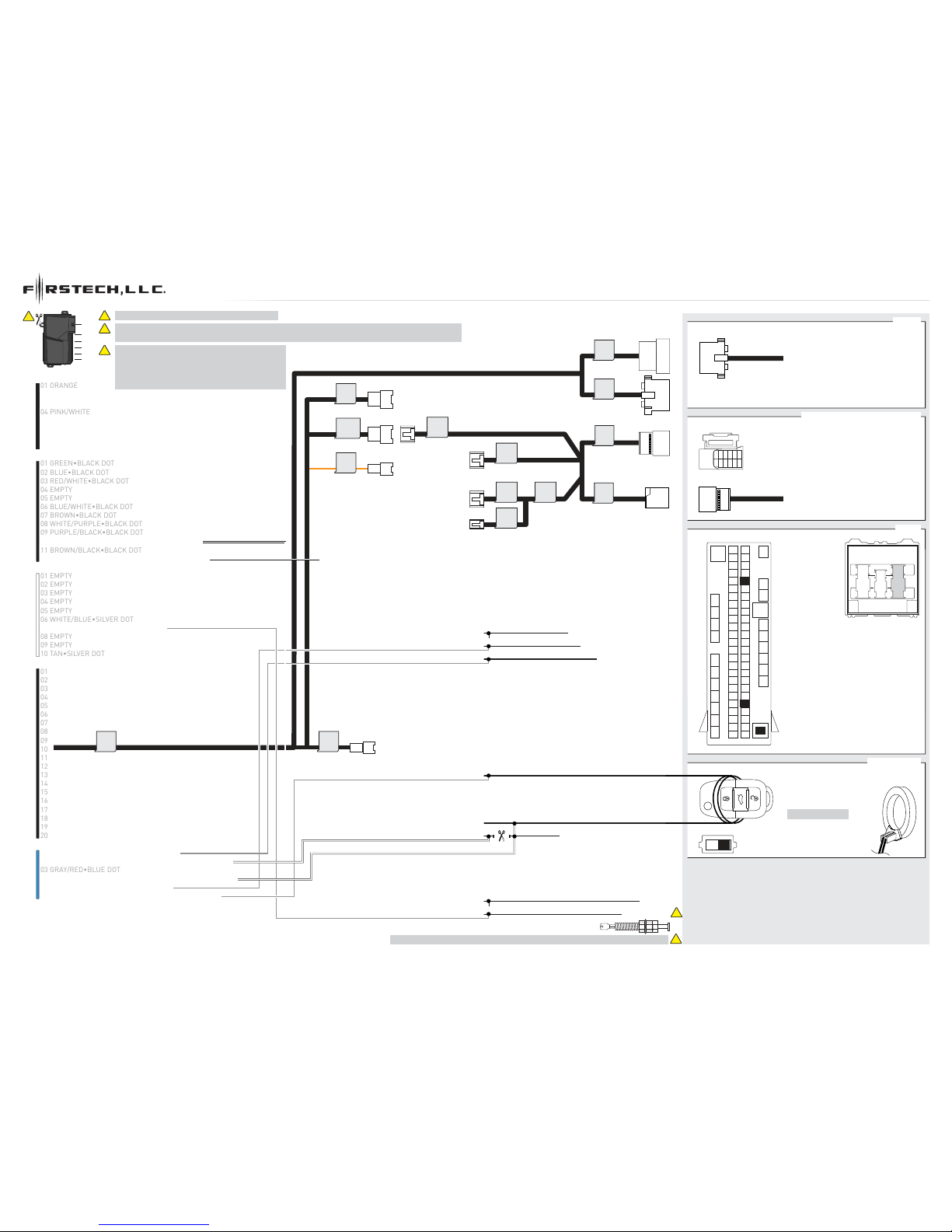
HARDWIRE / WIRING DIAGRAM - 1 OF 1
1
M5
M4
M2
M3
04 GREEN/WHITE•BLACK DOT04 GREEN/WHITE•BLACK DOT
03 BROWN/RED - CANH 103 BROWN/RED - CANH 1
04 BROWN/YELLOW - CANL 104 BROWN/YELLOW - CANL 1
OBDII (D)
CANH (DATA) ORANGE/GREEN - 16
CANL (DATA) ORANGE/BROWN - 15
IMMOBILIZER (DATA) BROWN - 02
PTS 1 (-) BLUE/YELLOW - 13
IMMOBILIZER (A)
06 BLUE/WHITE•BLACK DOT06 BLUE/WHITE•BLACK DOT
08 WHITE/PURPLE•BLACK DOT
01 GREEN•BLACK DOT01 GREEN•BLACK DOT
02 BLUE•BLACK DOT02 BLUE•BLACK DOT
03 RED/WHITE•BLACK DOT03 RED/WHITE•BLACK DOT
05 GREEN/BLACK•BLACK DOT05 GREEN/BLACK•BLACK DOT
07 EMPTY07 EMPTY
09 PURPLE/BLACK•BLACK DOT09 PURPLE/BLACK•BLACK DOT
11 BROWN/BLACK•BLACK DOT11 BROWN/BLACK•BLACK DOT
12 WHITE•BLACK DOT - PARKING LIGHT (-) OUTPUT12 WHITE•BLACK DOT - PARKING LIGHT (-) OUTPUT
01 BROWN•SILVER DOT01 BROWN•SILVER DOT
02 BLACK/WHITE•SILVER DOT02 BLACK/WHITE•SILVER DOT
03 PURPLE•SILVER DOT03 PURPLE•SILVER DOT
04 GREEN•SILVER DOT04 GREEN•SILVER DOT
05 PURPLE/WHITE•SILVER DOT05 PURPLE/WHITE•SILVER DOT
06 WHITE/BLUE•SILVER DOT06 WHITE/BLUE•SILVER DOT
08 BLUE•SILVER DOT08 BLUE•SILVER DOT
09 GRAY/BLACK•SILVER DOT09 GRAY/BLACK•SILVER DOT
10 EMPTY10 EMPTY
01 EMPTY01 EMPTY
02 EMPTY02 EMPTY
05 BLUE/RED05 BLUE/RED
06 BLUE/YELLOW06 BLUE/YELLOW
07 EMPTY07 EMPTY
08 ORANGE08 ORANGE
09 YELLOW09 YELLOW
10 EMPTY10 EMPTY
11 GRAY/RED - PTS (-) OUTPUT11 GRAY/RED - PTS (-) OUTPUT
12 GRAY/YELLOW12 GRAY/YELLOW
13 GREEN/RED - PTS (-) OUTPUT13 GREEN/RED - PTS (-) OUTPUT
14 ORANGE/WHITE - IGNITION (+) INPUT14 ORANGE/WHITE - IGNITION (+) INPUT
15 BROWN15 BROWN
16 ORANGE/BLACK16 ORANGE/BLACK
BRAKE (+) BLACK/RED - 58
17 PINK17 PINK
18 PURPLE18 PURPLE
19 RED - 12V (+) INPUT19 RED - 12V (+) INPUT
20 BLACK - GROUND (-)20 BLACK - GROUND (-)
01 GRAY/BLACK•BLUE DOT - 12V (+) INPUT01 GRAY/BLACK•BLUE DOT - 12V (+) INPUT
02 WHITE/BLACK•BLUE DOT - IMMOBILIZER VEHICLE SIDE
03 GRAY/RED•BLUE DOT03 GRAY/RED•BLUE DOT
04 WHITE/RED•BLUE DOT - IMMOBILIZER CONNECTOR SIDE
05 GRAY•BLUE DOT - BRAKE (+) OUTPUT
05 GRAY•BLUE DOT - BRAKE (+) OUTPUT
06 WHITE•BLUE DOT - IMMOBILIZER CONNECTOR SIDE
07 GRAY•SILVER DOT - HOOD (-) INPUT
07 GRAY•SILVER DOT - HOOD (-) INPUT
10 WHITE/BLACK•BLACK DOT - HORN (-) OUTPUT10 WHITE/BLACK•BLACK DOT - HORN (-) OUTPUT
HORN (-)
IGNITION (+) RED/BLUE - 01
HOOD SWITCH
INSTALL THE SUPPLIED HOOD SWITCH IF THE VEHICLE IS NOT EQUIPPED WITH ONE.
TWO KEYS ARE REQUIRED FOR THIS INSTALLATION.
ONE KEY WILL REMAIN PERMANENTLY IN THE VEHICLE.
THE OTHER KEY WILL BE USED FOR THE
PROGRAMMING PROCEDURE. IT WILL THEN BE
RETURNED TO THE OWNER.
20 LOOPS (24 AWG)
AROUND KEYFOB
12V (+) GRAY/PURPLE - 16
GROUND (-) BROWN - 04
PTS 2 (-) BLUE/WHITE - 04
1: BLACK
1: BLACK
STEERING COLUMN LOCK MODULE (B)
1
1
HAZARD (-) PURPLE/RED - 42
BCM (C)
1: BLACK/WHITE
1
10 11 12 13 14 15 16
1 2 3
4 5 6 7 8
9
16
3
4
5
6
1
2
17
16
15
14
13
18
19
20
7
8
11
12
9
10
23
24
25
26
21
22
37
38
39
40
27
28
35
36
31
32
33
34
29
30
43
44
45
46
41
42
57
58
59
60
47
48
55
56
51
52
53
54
67
68
69
70
71
72
73
65
66
61
62
63
64
49
50
M1
04 PINK/WHITE
01 ORANGE01 ORANGE
05 PINK05 PINK
02 RED02 RED
03 PURPLE03 PURPLE
07 RED07 RED
08 BLACK08 BLACK
06 WHITE06 WHITE
!
M3
M1
M2
M5
M4
M6
PAGE 5 OF 9
U.S. Patent No. 8,856,780 2015-2017 Audi A3 PTS AT
www.idatalink.comAutomotive Data Solutions Inc. © 2017 FTRSDVW7FTDC3HCEN
20170808
Page 6

01
ENGINE
START
STOP
STOP ACC ON START
ON
02
03
ENGINE
START
STOP
STOP ACC ON START
STOP
04
ENGINE
START
STOP
STOP ACC ON START
START
05
06
07
08
09
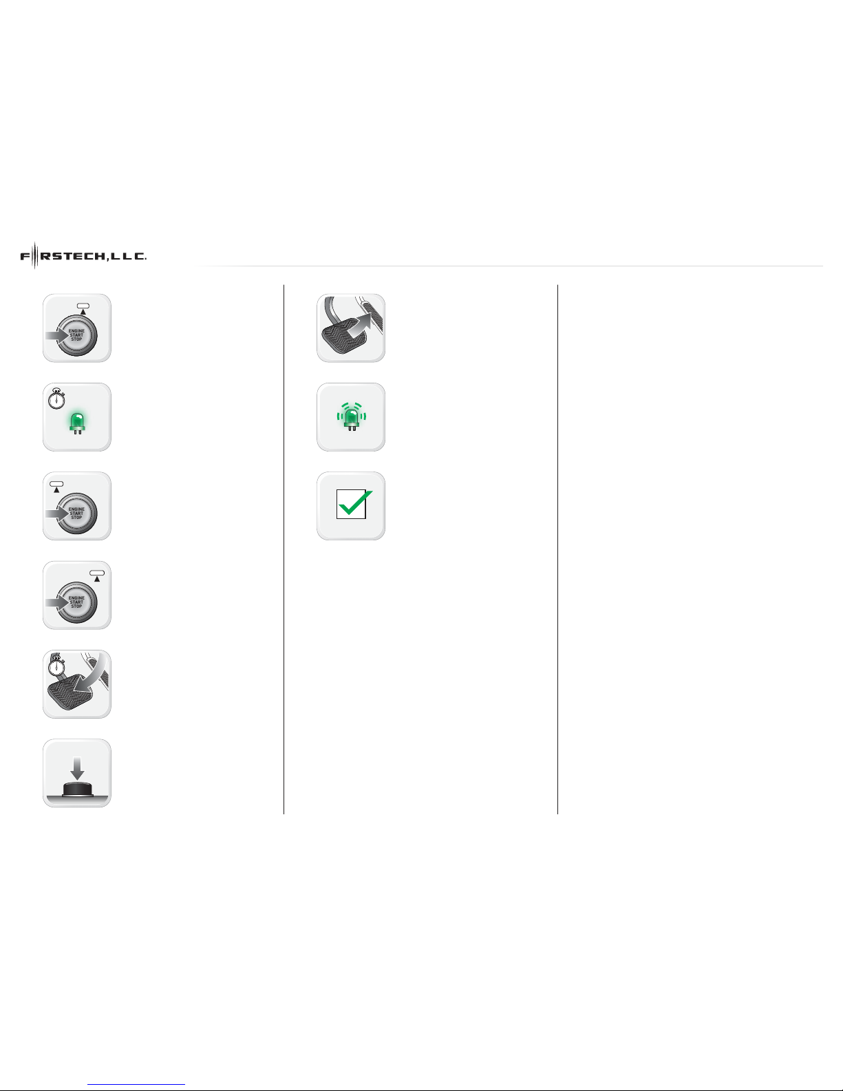
MODULE PROGRAMMING PROCEDURE - 1 OF 1
Set ignition to ON position.
Wait, LED 1 will turn solid GREEN for 2
seconds.
Set ignition to OFF position.
START vehicle for 15 seconds.
Press and hold the brake pedal.
Press and release the module’s programming
button.
Release the brake pedal.
Wait, LED 2 will flash GREEN.
Module Programming Procedure completed.
PAGE 6 OF 9
U.S. Patent No. 8,856,780 2015-2017 Audi A3 PTS AT
www.idatalink.comAutomotive Data Solutions Inc. © 2017 FTRSDVW7FTDC3HCEN
20170808
Page 7

>>
01
02
03
04
05
06
>>
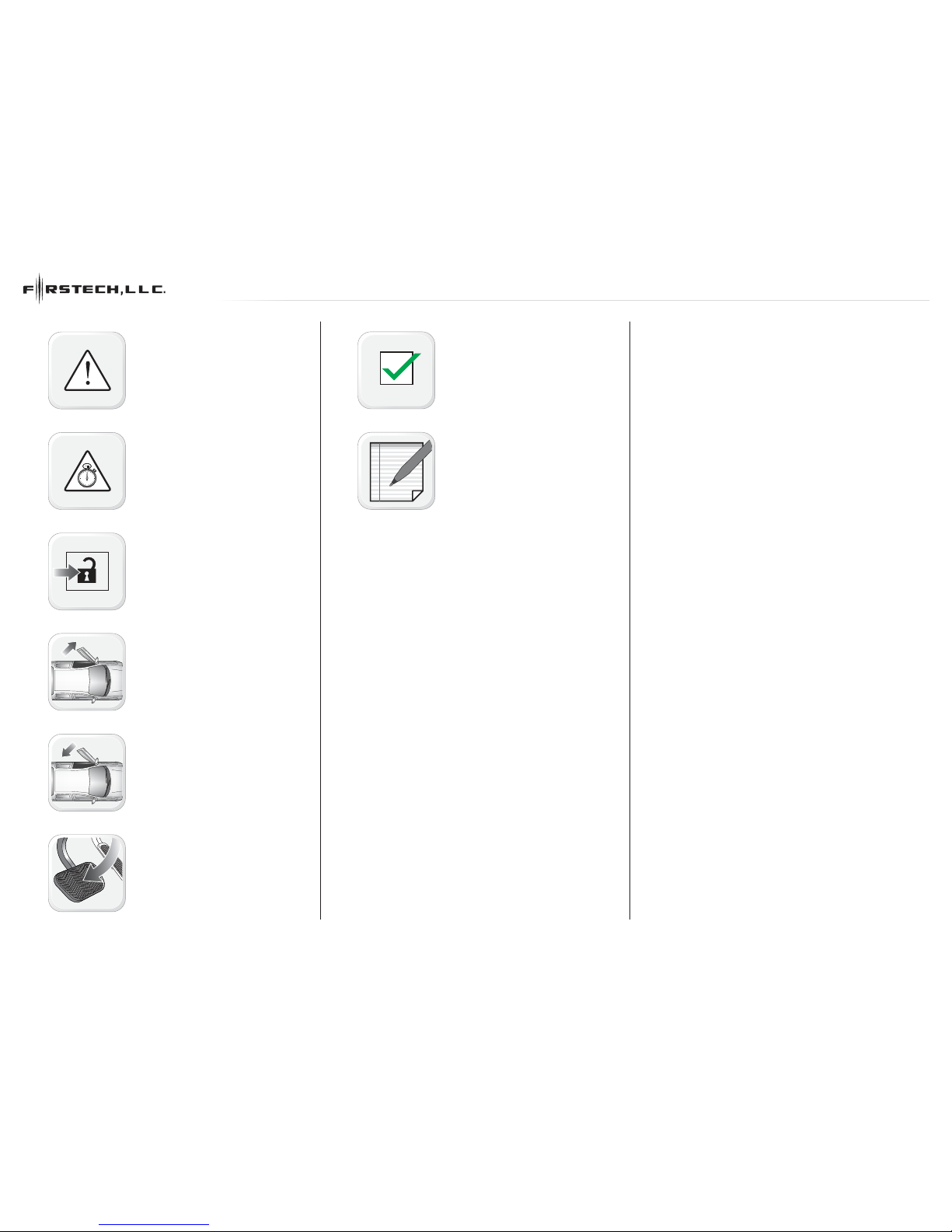
TAKEOVER PROCEDURE - PTS - 1 OF 1
All vehicle doors must be closed and locked
prior to remote start sequence.
Time restriction. Complete steps 2 to 5 within
45 seconds.
Press unlock on OEM or aftermarket remote.
Open driver door and enter vehicle.
Close driver door.
Press and release BRAKE pedal.
Take over procedure completed.
Failure to follow procedure will result in
vehicle engine shutdown.
PAGE 7 OF 9
U.S. Patent No. 8,856,780 2015-2017 Audi A3 PTS AT
www.idatalink.comAutomotive Data Solutions Inc. © 2017 FTRSDVW7FTDC3HCEN
20170808
Page 8

INSTALLATION CHECKLIST - 1 OF 2
1 WARNING: Vehicle engine will start many times. Test in a well ventilated area.
2 Close all vehicle doors, hood and trunk.
3 Press the LOCK button once [1x] on the aftermarket keyfob.
Question 1: Do the doors lock?
YES: Go to next step.
NO: Verify the remote programming, the RF connections and the wired door lock/unlock
connections as illustrated in the wiring diagram, if applicable. Repeat the test and call
technical support, if the problem persists.
4 Press the UNLOCK button once [1x] on the aftermarket keyfob.
Question 2: Do the doors unlock?
YES: Go to next step.
NO: Verify the remote programming, the RF connections and the wired door lock/unlock
connections as illustrated in the wiring diagram, if applicable. Repeat the test and call
technical support, if the problem persists.
5 Press the TRUNK release button once [1x] on the aftermarket keyfob if supported.
Question 3: Does the trunk or hatch open/unlock?
YES: Close trunk or hatch and go to next step.
NO: Verify the remote programming, the RF connections and the wired trunk/hatch
connections as illustrated in the wiring diagram, if applicable. Repeat the test and call
technical support, if the problem persists.
6 Press the AUX 1 button once [1x] on the aftermarket keyfob if supported.
Question 4: Does the driver side sliding door open?
YES: Press the AUX 1 button once [1x] to close the driver sliding door and go to next step.
NO: Verify the remote programming and the RF connections. Repeat the test and call
technical support, if the problem persists.
7 Press the AUX 2 button once [1x] on the aftermarket keyfob if supported.
Question 5: Does the passenger side sliding door open?
YES: Press the AUX 2 button once [1x] to close the passenger sliding door and go to next step.
NO: Verify the remote programming and the RF connections. Repeat the test and call
technical support, if the problem persists.
8 Press the START/STOP button once [1x] on the aftermarket keyfob to remote start vehicle.
Question 6: Does the vehicle remote start?
YES: Go to next step.
NO: Verify the remote programming, the RF connections and check the remote start error
codes. Repeat the test and call technical support, if the problem persists.
9 Press the START/STOP button once [1x] on the aftermarket keyfob to shut down vehicle.
Question 7: Does the vehicle shut down?
YES: Go to next step.
NO: Repeat step. If problem persists, press the brake pedal once [1x] to shut down the vehicle
and call technical support.
10 RAP and auto light shutdown test
Question 8: Did the radio, interior controls and headlights turn off within 60 seconds after
remote start shutdown?
YES: Go to next step.
NO: Verify the RAP SHUTDOWN connections as illustrated in the wiring diagram. Repeat the
test and call technical support if the problem persists.
11 Open hood.
12
If not already installed, affix the mandatory orange warning sticker under the hood and
proceed to next step.
13 Press the START/STOP button once [1x] on the aftermarket keyfob to remote start vehicle.
Question 9: Does the vehicle remote start?
YES: The vehicle is not equipped with a factory hood pin. Install a mandatory aftermarket hood
switch, then repeat the test.
NO: Go to next step.
14 Close hood.
15 Enter vehicle and close the doors.
16 Press the START/STOP button once [1x] on the aftermarket keyfob to remote start vehicle.
17 Wait for the vehicle to start.
18 Press brake pedal.
Question 10: Does the vehicle shut down?
YES: Go to next step.
NO: The module does NOT detect the brake pedal signal. Press the START/STOP button once
[1x] on the aftermarket keyfob to shut down vehicle, check connection as illustrated in the
wiring diagram, if applicable, and call technical support.
19 Exit vehicle.
20 Installation checklist completed.
CHECKLIST - WITH AFTERMARKET KEYFOB
PAGE 8 OF 9
U.S. Patent No. 8,856,780 2015-2017 Audi A3 PTS AT
www.idatalink.comAutomotive Data Solutions Inc. © 2017 FTRSDVW7FTDC3HCEN
20170808
Page 9

INSTALLATION CHECKLIST - 2 OF 2
CHECKLIST - WITH OEM KEYFOB
1 WARNING: Vehicle engine will start many times. Test in a well ventilated area.
2 Close all vehicle doors, hood and trunk.
3 Press LOCK button three times [3x] rapidly on the OEM keyfob to remote start vehicle.
Question 1: Does the vehicle remote start?
YES: Go to next step.
NO: The module doesn't detect OEM remote lock button from the vehicle communication network. Check all connections, repeat the test and call technical support, if the problem persists.
4 Press LOCK button three times [3x] rapidly on the OEM keyfob to shut down vehicle.
Question 2: Does the vehicle shut down?
YES: Go to next step.
NO: Repeat step. If the problem persists, press on the brake pedal once [1x] to shut down the vehicle and call technical support.
5 RAP Shutdown test
Question 3: Did the radio, interior controls, and headlights turn off within 60 seconds after remote start shutdown?
YES: Go to next step.
NO: Verify the RAP SHUTDOWN connections as illustrated in the wiring diagram. Repeat the test and call technical support, if the problem persists.
6 Open hood.
7 If not already installed, affix the mandatory orange warning sticker under the hood and proceed to next step.
8 Press LOCK button three times [3x] rapidly on the OEM keyfob to remote start vehicle.
Question 4: Does the vehicle remote start?
YES: The vehicle is not equipped with a factory hood pin. Install a mandatory aftermarket hood switch, then repeat the test.
NO: Go to next step.
9 Close hood.
10 Enter vehicle and close the doors.
11 Press LOCK button three times [3x] rapidly on the OEM keyfob to remote start vehicle.
12 Wait for the vehicle to start.
13 Press brake pedal.
Question 5: Does the vehicle shut down?
YES: Go to next step.
NO: The module does NOT detect the brake pedal signal. Press LOCK button three times [3x] rapidly on the OEM keyfob to shut down, check the brake connection as illustrated in the wiring diagram, if
applicable, and call technical support.
14 Exit vehicle.
15 Installation checklist completed.
PAGE 9 OF 9
U.S. Patent No. 8,856,780 2015-2017 Audi A3 PTS AT
www.idatalink.comAutomotive Data Solutions Inc. © 2017 FTRSDVW7FTDC3HCEN
20170808
Page 10
U.S. Patent No. 8,856,780
20170808
REVISION DATE
FT-RSD-VW7-[FT-DC3-HC]
FIRMWARE
FT-DC3-HC
HARDWARE
ADS-USB (OPTIONAL)
ADS-WLM-AN1/ADS-WLM-AP1 (OPTIONAL)
DRONE MOBILE DR-2000 (OPTIONAL)
COMPATIBLE RF-KIT (OPTIONAL)
ACCESSORIES
DOCUMENT NUMBER
2015-2017 AUDI S3 PTS AT
www.idatalink.comAutomotive Data Solutions Inc. © 2017
INSTALL GUIDE
NOTICE
The manufacturer will accept no responsability for any electrical damage resulting from
improper installation of this product, be that either damage to the vehicle itself or to the
installed device. This device must be installed by a certified technician. Please review the
Installation Guide carefully before beginning any work.
Page 11

T002_H
T-HARNESS / COMPONENT LOCATOR - 1 OF 1
B
C
D
A
PAGE 2 OF 9
U.S. Patent No. 8,856,780 2015-2017 Audi S3 PTS AT
www.idatalink.comAutomotive Data Solutions Inc. © 2017 FTRSDVW7FTDC3HCEN
20170808
Page 12
!
CUT LOOP FOR AUTOMATIC TRANSMISSION ONLYCUT LOOP FOR AUTOMATIC TRANSMISSION ONLY
1
2
SOME PARTS OF THE T-HARNESS (VS5/VS6, VS7/VS8, VS9/VS10 AND JS9) ARE NOT USED IN THIS INSTALL
DO NOT CONNECT THEM.
SOME PARTS OF THE T-HARNESS (VS5/VS6, VS7/VS8, VS9/VS10 AND JS9) ARE NOT USED IN THIS INSTALL
DO NOT CONNECT THEM.
TWO KEYS ARE REQUIRED FOR THIS INSTALLATION.
ONE KEY WILL REMAIN PERMANENTLY IN THE
VEHICLE. THE OTHER KEY WILL BE USED FOR THE
PROGRAMMING PROCEDURE. IT WILL THEN BE
RETURNED TO THE OWNER.
12V (+) RED/BLUE - 73
HORN (-)
3
3
T002_H
T-HARNESS / WIRING DIAGRAM - 1 OF 1
M5
M4
M2
M3
OBDII (A)
HAZARDS (-) PURPLE/RED - 42
BRAKE (+) BLACK/RED - 58
HOOD SWITCH
INSTALL THE SUPPLIED HOOD SWITCH IF THE VEHICLE IS NOT EQUIPPED WITH ONE.
JS1
VS1
VS2
1: OBDII CONNECTOR
1: OBDII HOLDER
NC
NC
NC
JS2
JS4
GOLF
MS1 JS3
BCM (C)
1: BLACK/WHITE
1
1
2
REMOVE BATTERY
IMMOBILIZER (DATA) BROWN - 02
IMMOBILIZER (D)
20 LOOPS (24 AWG)
AROUND KEYFOB
1: BLACK
1
01 GRAY/BLACK•BLUE DOT - 12V (+) INPUT
01 GRAY/BLACK•BLUE DOT - 12V (+) INPUT
02 WHITE/BLACK•BLUE DOT - IMMOBILIZER VEHICLE SIDE
03 GRAY/RED•BLUE DOT03 GRAY/RED•BLUE DOT
04 WHITE/RED•BLUE DOT - IMMOBILIZER CONNECTOR SIDE
05 GRAY•BLUE DOT - BRAKE (+) OUTPUT
05 GRAY•BLUE DOT - BRAKE (+) OUTPUT
06 WHITE•BLUE DOT - IMMOBILIZER CONNECTOR SIDE
04 EMPTY04 EMPTY
06 BLUE/WHITE•BLACK DOT06 BLUE/WHITE•BLACK DOT
08 WHITE/PURPLE•BLACK DOT
01 GREEN•BLACK DOT01 GREEN•BLACK DOT
02 BLUE•BLACK DOT02 BLUE•BLACK DOT
03 RED/WHITE•BLACK DOT03 RED/WHITE•BLACK DOT
05 EMPTY05 EMPTY
07 BROWN•BLACK DOT07 BROWN•BLACK DOT
09 PURPLE/BLACK•BLACK DOT09 PURPLE/BLACK•BLACK DOT
11 BROWN/BLACK•BLACK DOT11 BROWN/BLACK•BLACK DOT
12 WHITE•BLACK DOT - PARKING LIGHT (-) OUTPUT12 WHITE•BLACK DOT - PARKING LIGHT (-) OUTPUT
01 EMPTY01 EMPTY
02 EMPTY02 EMPTY
03 EMPTY03 EMPTY
04 EMPTY04 EMPTY
05 EMPTY05 EMPTY
06 WHITE/BLUE•SILVER DOT06 WHITE/BLUE•SILVER DOT
08 EMPTY08 EMPTY
09 EMPTY09 EMPTY
10 TAN•SILVER DOT10 TAN•SILVER DOT
07 GRAY•SILVER DOT - HOOD (-) INPUT07 GRAY•SILVER DOT - HOOD (-) INPUT
10 WHITE/BLACK•BLACK DOT - HORN (-) OUTPUT10 WHITE/BLACK•BLACK DOT - HORN (-) OUTPUT
0303
0404
0101
0202
0505
0606
0707
0808
0909
1010
1111
1212
1313
1414
1515
1616
1717
1818
1919
2020
NC
NC
NC
JS5
PTS
VS4
VS3
JS6
KEY
JS7 CC
JS8
1: BLACK CONNECTOR
1: HARNESS
STEERING COLUMN LOCK MODULE (B)
3
4
5
6
1
2
17
16
15
14
13
18
19
20
7
8
11
12
9
10
23
24
25
26
21
22
37
38
39
40
27
28
35
36
31
32
33
34
29
30
43
44
45
46
41
42
57
58
59
60
47
48
55
56
51
52
53
54
67
68
69
70
71
72
73
65
66
61
62
63
64
49
50
M1
04 PINK/WHITE
01 ORANGE01 ORANGE
02 RED - 12V (+)02 RED - 12V (+)
03 PURPLE - STARTER (+)03 PURPLE - STARTER (+)
05 PINK - IGNITION (+)
05 PINK - IGNITION (+)
07 RED - 12V (+)
07 RED - 12V (+)
08 BLACK - GROUND08 BLACK - GROUND
06 WHITE - PARKING LIGHT (+)
06 WHITE - PARKING LIGHT (+)
!
M3
M1
M2
M5
M4
M6
PAGE 3 OF 9
U.S. Patent No. 8,856,780 2015-2017 Audi S3 PTS AT
www.idatalink.comAutomotive Data Solutions Inc. © 2017 FTRSDVW7FTDC3HCEN
20170808
Page 13

T002_W
HARDWIRE / COMPONENT LOCATOR - 1 OF 1
A
C
B
D
PAGE 4 OF 9
U.S. Patent No. 8,856,780 2015-2017 Audi S3 PTS AT
www.idatalink.comAutomotive Data Solutions Inc. © 2017 FTRSDVW7FTDC3HCEN
20170808
Page 14

!
2
2
1
T002_W
1
2
REMOVE BATTERY
78 6 5 4 3 2 1
16 15 14 13 12 11 10 9
CUT LOOP FOR AUTOMATIC TRANSMISSION ONLYCUT LOOP FOR AUTOMATIC TRANSMISSION ONLY
HARDWIRE / WIRING DIAGRAM - 1 OF 1
1
M5
M4
M2
M3
04 GREEN/WHITE•BLACK DOT04 GREEN/WHITE•BLACK DOT
03 BROWN/RED - CANH 103 BROWN/RED - CANH 1
04 BROWN/YELLOW - CANL 104 BROWN/YELLOW - CANL 1
OBDII (D)
CANH (DATA) ORANGE/GREEN - 16
CANL (DATA) ORANGE/BROWN - 15
IMMOBILIZER (DATA) BROWN - 02
PTS 1 (-) BLUE/YELLOW - 13
IMMOBILIZER (A)
06 BLUE/WHITE•BLACK DOT06 BLUE/WHITE•BLACK DOT
08 WHITE/PURPLE•BLACK DOT
01 GREEN•BLACK DOT01 GREEN•BLACK DOT
02 BLUE•BLACK DOT02 BLUE•BLACK DOT
03 RED/WHITE•BLACK DOT03 RED/WHITE•BLACK DOT
05 GREEN/BLACK•BLACK DOT05 GREEN/BLACK•BLACK DOT
07 EMPTY07 EMPTY
09 PURPLE/BLACK•BLACK DOT09 PURPLE/BLACK•BLACK DOT
11 BROWN/BLACK•BLACK DOT11 BROWN/BLACK•BLACK DOT
12 WHITE•BLACK DOT - PARKING LIGHT (-) OUTPUT12 WHITE•BLACK DOT - PARKING LIGHT (-) OUTPUT
01 BROWN•SILVER DOT01 BROWN•SILVER DOT
02 BLACK/WHITE•SILVER DOT02 BLACK/WHITE•SILVER DOT
03 PURPLE•SILVER DOT03 PURPLE•SILVER DOT
04 GREEN•SILVER DOT04 GREEN•SILVER DOT
05 PURPLE/WHITE•SILVER DOT05 PURPLE/WHITE•SILVER DOT
06 WHITE/BLUE•SILVER DOT06 WHITE/BLUE•SILVER DOT
08 BLUE•SILVER DOT08 BLUE•SILVER DOT
09 GRAY/BLACK•SILVER DOT09 GRAY/BLACK•SILVER DOT
10 EMPTY10 EMPTY
01 EMPTY01 EMPTY
02 EMPTY02 EMPTY
05 BLUE/RED05 BLUE/RED
06 BLUE/YELLOW06 BLUE/YELLOW
07 EMPTY07 EMPTY
08 ORANGE08 ORANGE
09 YELLOW09 YELLOW
10 EMPTY10 EMPTY
11 GRAY/RED - PTS (-) OUTPUT11 GRAY/RED - PTS (-) OUTPUT
12 GRAY/YELLOW12 GRAY/YELLOW
13 GREEN/RED - PTS (-) OUTPUT13 GREEN/RED - PTS (-) OUTPUT
14 ORANGE/WHITE - IGNITION (+) INPUT14 ORANGE/WHITE - IGNITION (+) INPUT
15 BROWN15 BROWN
16 ORANGE/BLACK16 ORANGE/BLACK
BRAKE (+) BLACK/RED - 58
17 PINK17 PINK
18 PURPLE18 PURPLE
19 RED - 12V (+) INPUT19 RED - 12V (+) INPUT
20 BLACK - GROUND (-)20 BLACK - GROUND (-)
01 GRAY/BLACK•BLUE DOT - 12V (+) INPUT01 GRAY/BLACK•BLUE DOT - 12V (+) INPUT
02 WHITE/BLACK•BLUE DOT - IMMOBILIZER VEHICLE SIDE
03 GRAY/RED•BLUE DOT03 GRAY/RED•BLUE DOT
04 WHITE/RED•BLUE DOT - IMMOBILIZER CONNECTOR SIDE
05 GRAY•BLUE DOT - BRAKE (+) OUTPUT
05 GRAY•BLUE DOT - BRAKE (+) OUTPUT
06 WHITE•BLUE DOT - IMMOBILIZER CONNECTOR SIDE
07 GRAY•SILVER DOT - HOOD (-) INPUT
07 GRAY•SILVER DOT - HOOD (-) INPUT
10 WHITE/BLACK•BLACK DOT - HORN (-) OUTPUT10 WHITE/BLACK•BLACK DOT - HORN (-) OUTPUT
HORN (-)
IGNITION (+) RED/BLUE - 01
HOOD SWITCH
INSTALL THE SUPPLIED HOOD SWITCH IF THE VEHICLE IS NOT EQUIPPED WITH ONE.
TWO KEYS ARE REQUIRED FOR THIS INSTALLATION.
ONE KEY WILL REMAIN PERMANENTLY IN THE VEHICLE.
THE OTHER KEY WILL BE USED FOR THE
PROGRAMMING PROCEDURE. IT WILL THEN BE
RETURNED TO THE OWNER.
20 LOOPS (24 AWG)
AROUND KEYFOB
12V (+) GRAY/PURPLE - 16
GROUND (-) BROWN - 04
PTS 2 (-) BLUE/WHITE - 04
1: BLACK
1: BLACK
STEERING COLUMN LOCK MODULE (B)
1
1
HAZARD (-) PURPLE/RED - 42
BCM (C)
1: BLACK/WHITE
1
10 11 12 13 14 15 16
1 2 3
4 5 6 7 8
9
16
3
4
5
6
1
2
17
16
15
14
13
18
19
20
7
8
11
12
9
10
23
24
25
26
21
22
37
38
39
40
27
28
35
36
31
32
33
34
29
30
43
44
45
46
41
42
57
58
59
60
47
48
55
56
51
52
53
54
67
68
69
70
71
72
73
65
66
61
62
63
64
49
50
M1
04 PINK/WHITE
01 ORANGE01 ORANGE
05 PINK05 PINK
02 RED02 RED
03 PURPLE03 PURPLE
07 RED07 RED
08 BLACK08 BLACK
06 WHITE06 WHITE
!
M3
M1
M2
M5
M4
M6
PAGE 5 OF 9
U.S. Patent No. 8,856,780 2015-2017 Audi S3 PTS AT
www.idatalink.comAutomotive Data Solutions Inc. © 2017 FTRSDVW7FTDC3HCEN
20170808
Page 15
01
ENGINE
START
STOP
STOP ACC ON START
ON
02
03
ENGINE
START
STOP
STOP ACC ON START
STOP
04
ENGINE
START
STOP
STOP ACC ON START
START
05
06
07
08
09
MODULE PROGRAMMING PROCEDURE - 1 OF 1
Set ignition to ON position.
Wait, LED 1 will turn solid GREEN for 2
seconds.
Set ignition to OFF position.
START vehicle for 15 seconds.
Press and hold the brake pedal.
Press and release the module’s programming
button.
Release the brake pedal.
Wait, LED 2 will flash GREEN.
Module Programming Procedure completed.
PAGE 6 OF 9
U.S. Patent No. 8,856,780 2015-2017 Audi S3 PTS AT
www.idatalink.comAutomotive Data Solutions Inc. © 2017 FTRSDVW7FTDC3HCEN
20170808
Page 16
>>
01
02
03
04
05
06
>>
TAKEOVER PROCEDURE - PTS - 1 OF 1
All vehicle doors must be closed and locked
prior to remote start sequence.
Time restriction. Complete steps 2 to 5 within
45 seconds.
Press unlock on OEM or aftermarket remote.
Open driver door and enter vehicle.
Close driver door.
Press and release BRAKE pedal.
Take over procedure completed.
Failure to follow procedure will result in
vehicle engine shutdown.
PAGE 7 OF 9
U.S. Patent No. 8,856,780 2015-2017 Audi S3 PTS AT
www.idatalink.comAutomotive Data Solutions Inc. © 2017 FTRSDVW7FTDC3HCEN
20170808
Page 17

INSTALLATION CHECKLIST - 1 OF 2
1 WARNING: Vehicle engine will start many times. Test in a well ventilated area.
2 Close all vehicle doors, hood and trunk.
3 Press the LOCK button once [1x] on the aftermarket keyfob.
Question 1: Do the doors lock?
YES: Go to next step.
NO: Verify the remote programming, the RF connections and the wired door lock/unlock
connections as illustrated in the wiring diagram, if applicable. Repeat the test and call
technical support, if the problem persists.
4 Press the UNLOCK button once [1x] on the aftermarket keyfob.
Question 2: Do the doors unlock?
YES: Go to next step.
NO: Verify the remote programming, the RF connections and the wired door lock/unlock
connections as illustrated in the wiring diagram, if applicable. Repeat the test and call
technical support, if the problem persists.
5 Press the TRUNK release button once [1x] on the aftermarket keyfob if supported.
Question 3: Does the trunk or hatch open/unlock?
YES: Close trunk or hatch and go to next step.
NO: Verify the remote programming, the RF connections and the wired trunk/hatch
connections as illustrated in the wiring diagram, if applicable. Repeat the test and call
technical support, if the problem persists.
6 Press the AUX 1 button once [1x] on the aftermarket keyfob if supported.
Question 4: Does the driver side sliding door open?
YES: Press the AUX 1 button once [1x] to close the driver sliding door and go to next step.
NO: Verify the remote programming and the RF connections. Repeat the test and call
technical support, if the problem persists.
7 Press the AUX 2 button once [1x] on the aftermarket keyfob if supported.
Question 5: Does the passenger side sliding door open?
YES: Press the AUX 2 button once [1x] to close the passenger sliding door and go to next step.
NO: Verify the remote programming and the RF connections. Repeat the test and call
technical support, if the problem persists.
8 Press the START/STOP button once [1x] on the aftermarket keyfob to remote start vehicle.
Question 6: Does the vehicle remote start?
YES: Go to next step.
NO: Verify the remote programming, the RF connections and check the remote start error
codes. Repeat the test and call technical support, if the problem persists.
9 Press the START/STOP button once [1x] on the aftermarket keyfob to shut down vehicle.
Question 7: Does the vehicle shut down?
YES: Go to next step.
NO: Repeat step. If problem persists, press the brake pedal once [1x] to shut down the vehicle
and call technical support.
10 RAP and auto light shutdown test
Question 8: Did the radio, interior controls and headlights turn off within 60 seconds after
remote start shutdown?
YES: Go to next step.
NO: Verify the RAP SHUTDOWN connections as illustrated in the wiring diagram. Repeat the
test and call technical support if the problem persists.
11 Open hood.
12
If not already installed, affix the mandatory orange warning sticker under the hood and
proceed to next step.
13 Press the START/STOP button once [1x] on the aftermarket keyfob to remote start vehicle.
Question 9: Does the vehicle remote start?
YES: The vehicle is not equipped with a factory hood pin. Install a mandatory aftermarket hood
switch, then repeat the test.
NO: Go to next step.
14 Close hood.
15 Enter vehicle and close the doors.
16 Press the START/STOP button once [1x] on the aftermarket keyfob to remote start vehicle.
17 Wait for the vehicle to start.
18 Press brake pedal.
Question 10: Does the vehicle shut down?
YES: Go to next step.
NO: The module does NOT detect the brake pedal signal. Press the START/STOP button once
[1x] on the aftermarket keyfob to shut down vehicle, check connection as illustrated in the
wiring diagram, if applicable, and call technical support.
19 Exit vehicle.
20 Installation checklist completed.
CHECKLIST - WITH AFTERMARKET KEYFOB
PAGE 8 OF 9
U.S. Patent No. 8,856,780 2015-2017 Audi S3 PTS AT
www.idatalink.comAutomotive Data Solutions Inc. © 2017 FTRSDVW7FTDC3HCEN
20170808
Page 18

INSTALLATION CHECKLIST - 2 OF 2
CHECKLIST - WITH OEM KEYFOB
1 WARNING: Vehicle engine will start many times. Test in a well ventilated area.
2 Close all vehicle doors, hood and trunk.
3 Press LOCK button three times [3x] rapidly on the OEM keyfob to remote start vehicle.
Question 1: Does the vehicle remote start?
YES: Go to next step.
NO: The module doesn't detect OEM remote lock button from the vehicle communication network. Check all connections, repeat the test and call technical support, if the problem persists.
4 Press LOCK button three times [3x] rapidly on the OEM keyfob to shut down vehicle.
Question 2: Does the vehicle shut down?
YES: Go to next step.
NO: Repeat step. If the problem persists, press on the brake pedal once [1x] to shut down the vehicle and call technical support.
5 RAP Shutdown test
Question 3: Did the radio, interior controls, and headlights turn off within 60 seconds after remote start shutdown?
YES: Go to next step.
NO: Verify the RAP SHUTDOWN connections as illustrated in the wiring diagram. Repeat the test and call technical support, if the problem persists.
6 Open hood.
7 If not already installed, affix the mandatory orange warning sticker under the hood and proceed to next step.
8 Press LOCK button three times [3x] rapidly on the OEM keyfob to remote start vehicle.
Question 4: Does the vehicle remote start?
YES: The vehicle is not equipped with a factory hood pin. Install a mandatory aftermarket hood switch, then repeat the test.
NO: Go to next step.
9 Close hood.
10 Enter vehicle and close the doors.
11 Press LOCK button three times [3x] rapidly on the OEM keyfob to remote start vehicle.
12 Wait for the vehicle to start.
13 Press brake pedal.
Question 5: Does the vehicle shut down?
YES: Go to next step.
NO: The module does NOT detect the brake pedal signal. Press LOCK button three times [3x] rapidly on the OEM keyfob to shut down, check the brake connection as illustrated in the wiring diagram, if
applicable, and call technical support.
14 Exit vehicle.
15 Installation checklist completed.
PAGE 9 OF 9
U.S. Patent No. 8,856,780 2015-2017 Audi S3 PTS AT
www.idatalink.comAutomotive Data Solutions Inc. © 2017 FTRSDVW7FTDC3HCEN
20170808
Page 19

U.S. Patent No. 8,856,780
20170808
REVISION DATE
FT-RSD-VW7-[FT-DC3-HC]
FIRMWARE
FT-DC3-HC
HARDWARE
ADS-USB (OPTIONAL)
ADS-WLM-AN1/ADS-WLM-AP1 (OPTIONAL)
DRONE MOBILE DR-2000 (OPTIONAL)
COMPATIBLE RF-KIT (OPTIONAL)
ACCESSORIES
DOCUMENT NUMBER
2018 VOLKSWAGEN ATLAS PTS AT
www.idatalink.comAutomotive Data Solutions Inc. © 2017
INSTALL GUIDE
NOTICE
The manufacturer will accept no responsability for any electrical damage resulting from
improper installation of this product, be that either damage to the vehicle itself or to the
installed device. This device must be installed by a certified technician. Please review the
Installation Guide carefully before beginning any work.
Page 20

T003_W
HARDWIRE / COMPONENT LOCATOR - 1 OF 1
A
E
C
B
D
PAGE 2 OF 7
U.S. Patent No. 8,856,780 2018 Volkswagen Atlas PTS AT
www.idatalink.comAutomotive Data Solutions Inc. © 2017 FT-RSD-VW7-[FT-DC3-HC]-EN
20170808
Page 21

!
2
2
1
T003_W
REMOVE BATTERY
786 5 4 3 2
1
14 13 12 11 10 9
10 11 12 13 14 15 16
1 2 3
4 5 6 7 8
9
16
CUT LOOP FOR AUTOMATIC TRANSMISSION ONLYCUT LOOP FOR AUTOMATIC TRANSMISSION ONLY
HARDWIRE / WIRING DIAGRAM - 1 OF 1
1
M5
M4
M2
M3
04 GREEN/WHITE•BLACK DOT04 GREEN/WHITE•BLACK DOT
03 BROWN/RED - CANH 103 BROWN/RED - CANH 1
04 BROWN/YELLOW - CANL 104 BROWN/YELLOW - CANL 1
BCM (C)
OBDII (D)
1: BLACK
PTS SWITCH (E)
CANH (DATA) ORANGE/GREEN OR GREEN - 06
CANL (DATA) ORANGE/BROWN - 05
PTS 1 (-) PURPLE - 03
IMMOBILIZER RECEIVER (A)
06 BLUE/WHITE•BLACK DOT06 BLUE/WHITE•BLACK DOT
08 WHITE/PURPLE•BLACK DOT
01 GREEN•BLACK DOT01 GREEN•BLACK DOT
02 BLUE•BLACK DOT02 BLUE•BLACK DOT
03 RED/WHITE•BLACK DOT03 RED/WHITE•BLACK DOT
05 GREEN/BLACK•BLACK DOT05 GREEN/BLACK•BLACK DOT
07 EMPTY07 EMPTY
09 PURPLE/BLACK•BLACK DOT09 PURPLE/BLACK•BLACK DOT
11 BROWN/BLACK•BLACK DOT11 BROWN/BLACK•BLACK DOT
12 WHITE•BLACK DOT - PARKING LIGHTS (-) OUTPUT12 WHITE•BLACK DOT - PARKING LIGHTS (-) OUTPUT
01 BROWN•SILVER DOT01 BROWN•SILVER DOT
02 BLACK/WHITE•SILVER DOT02 BLACK/WHITE•SILVER DOT
03 PURPLE•SILVER DOT03 PURPLE•SILVER DOT
04 GREEN•SILVER DOT04 GREEN•SILVER DOT
05 PURPLE/WHITE•SILVER DOT05 PURPLE/WHITE•SILVER DOT
06 WHITE/BLUE•SILVER DOT06 WHITE/BLUE•SILVER DOT
08 BLUE•SILVER DOT08 BLUE•SILVER DOT
09 GRAY/BLACK•SILVER DOT09 GRAY/BLACK•SILVER DOT
10 EMPTY10 EMPTY
01 EMPTY01 EMPTY
02 EMPTY02 EMPTY
05 BLUE/RED05 BLUE/RED
06 BLUE/YELLOW06 BLUE/YELLOW
07 EMPTY07 EMPTY
08 ORANGE08 ORANGE
09 YELLOW09 YELLOW
10 EMPTY10 EMPTY
11 GRAY/RED - PTS (-) OUTPUT11 GRAY/RED - PTS (-) OUTPUT
12 GRAY/YELLOW12 GRAY/YELLOW
13 GREEN/RED - PTS (-) OUTPUT13 GREEN/RED - PTS (-) OUTPUT
14 ORANGE/WHITE - IGNITION (+) INPUT14 ORANGE/WHITE - IGNITION (+) INPUT
15 BROWN15 BROWN
16 ORANGE/BLACK16 ORANGE/BLACK
BRAKE (+) BLACK/RED - 58
17 PINK17 PINK
18 PURPLE18 PURPLE
19 RED - 12V (+) INPUT19 RED - 12V (+) INPUT
20 BLACK - GROUND (-)20 BLACK - GROUND (-)
01 GRAY/BLACK•BLUE DOT - 12V (+) VEHICLE SIDE01 GRAY/BLACK•BLUE DOT - 12V (+) VEHICLE SIDE
02 WHITE/BLACK•BLUE DOT
03 GRAY/RED•BLUE DOT03 GRAY/RED•BLUE DOT
04 WHITE/RED•BLUE DOT
05 GRAY•BLUE DOT - BRAKE (+) OUTPUT05 GRAY•BLUE DOT - BRAKE (+) OUTPUT
06 WHITE•BLUE DOT
07 GRAY•SILVER DOT - HOOD (-) INPUT
07 GRAY•SILVER DOT - HOOD (-) INPUT
10 WHITE/BLACK•BLACK DOT - HORN (-) OUTPUT10 WHITE/BLACK•BLACK DOT - HORN (-) OUTPUT
HORN (-)
IGNITION (+) BLACK/BLUE - 01
HOOD SWITCH
INSTALL THE SUPPLIED HOOD SWITCH IF THE VEHICLE IS NOT EQUIPPED WITH ONE.
TWO KEYS ARE REQUIRED FOR THIS INSTALLATION.
ONE KEY WILL REMAIN PERMANENTLY IN THE VEHICLE.
THE OTHER KEY WILL BE USED FOR THE
PROGRAMMING PROCEDURE. IT WILL THEN BE
RETURNED TO THE OWNER.
7-8 LOOPS
BACKSIDE OF KEYFOB
12V (+) RED/WHITE - 16
GROUND (-) BROWN - 04
HAZARDS (-) PURPLE/YELLOW - 42
PTS 2 (-) PURPLE/BLUE - 06
5-6 LOOPS ON
IMMOBILIZER RECEIVER
1: BLACK
3
4
5
6
1
2
17
16
15
14
13
18
19
20
7
8
11
12
9
10
23
24
25
26
21
22
37
38
39
40
27
28
35
36
31
32
33
34
29
30
43
44
45
46
41
42
57
58
59
60
47
48
55
56
51
52
53
54
67
68
69
70
71
72
73
65
66
61
62
63
64
49
50
1: BLACK/WHITE
MODULE, BOTTOM OF STEERING COLUMN (B)
1
11 22
3
44 55
6
M1
04 PINK/WHITE
01 ORANGE01 ORANGE
05 PINK05 PINK
02 RED02 RED
03 PURPLE03 PURPLE
07 RED07 RED
08 BLACK08 BLACK
06 WHITE06 WHITE
!
M3
M1
M2
M5
M4
M6
PAGE 3 OF 7
U.S. Patent No. 8,856,780 2018 Volkswagen Atlas PTS AT
www.idatalink.comAutomotive Data Solutions Inc. © 2017 FT-RSD-VW7-[FT-DC3-HC]-EN
20170808
Page 22

01
ENGINE
START
STOP
STOP ACC ON START
ON
02
03
ENGINE
START
STOP
STOP ACC ON START
STOP
04
ENGINE
START
STOP
STOP ACC ON START
START
05
06
07
08
09
MODULE PROGRAMMING PROCEDURE - 1 OF 1
Set ignition to ON position.
Wait, LED 1 will turn solid GREEN for 2
seconds.
Set ignition to OFF position.
START vehicle for 15 seconds.
Press and hold the brake pedal.
Press and release the module’s programming
button.
Release the brake pedal.
Wait, LED 2 will flash GREEN.
Module Programming Procedure completed.
PAGE 4 OF 7
U.S. Patent No. 8,856,780 2018 Volkswagen Atlas PTS AT
www.idatalink.comAutomotive Data Solutions Inc. © 2017 FT-RSD-VW7-[FT-DC3-HC]-EN
20170808
Page 23

>>
01
02
03
04
05
06
>>
TAKEOVER PROCEDURE - PTS - 1 OF 1
All vehicle doors must be closed and locked
prior to remote start sequence.
Time restriction. Complete steps 2 to 5 within
45 seconds.
Press unlock on OEM or aftermarket remote.
Open driver door and enter vehicle.
Close driver door.
Press and release BRAKE pedal.
Take over procedure completed.
Failure to follow procedure will result in
vehicle engine shutdown.
PAGE 5 OF 7
U.S. Patent No. 8,856,780 2018 Volkswagen Atlas PTS AT
www.idatalink.comAutomotive Data Solutions Inc. © 2017 FT-RSD-VW7-[FT-DC3-HC]-EN
20170808
Page 24

INSTALLATION CHECKLIST - 1 OF 2
1 WARNING: Vehicle engine will start many times. Test in a well ventilated area.
2 Close all vehicle doors, hood and trunk.
3 Press the LOCK button once [1x] on the aftermarket keyfob.
Question 1: Do the doors lock?
YES: Go to next step.
NO: Verify the remote programming, the RF connections and the wired door lock/unlock
connections as illustrated in the wiring diagram, if applicable. Repeat the test and call
technical support, if the problem persists.
4 Press the UNLOCK button once [1x] on the aftermarket keyfob.
Question 2: Do the doors unlock?
YES: Go to next step.
NO: Verify the remote programming, the RF connections and the wired door lock/unlock
connections as illustrated in the wiring diagram, if applicable. Repeat the test and call
technical support, if the problem persists.
5 Press the TRUNK release button once [1x] on the aftermarket keyfob if supported.
Question 3: Does the trunk or hatch open/unlock?
YES: Close trunk or hatch and go to next step.
NO: Verify the remote programming, the RF connections and the wired trunk/hatch
connections as illustrated in the wiring diagram, if applicable. Repeat the test and call
technical support, if the problem persists.
6 Press the AUX 1 button once [1x] on the aftermarket keyfob if supported.
Question 4: Does the driver side sliding door open?
YES: Press the AUX 1 button once [1x] to close the driver sliding door and go to next step.
NO: Verify the remote programming and the RF connections. Repeat the test and call
technical support, if the problem persists.
7 Press the AUX 2 button once [1x] on the aftermarket keyfob if supported.
Question 5: Does the passenger side sliding door open?
YES: Press the AUX 2 button once [1x] to close the passenger sliding door and go to next step.
NO: Verify the remote programming and the RF connections. Repeat the test and call
technical support, if the problem persists.
8 Press the START/STOP button once [1x] on the aftermarket keyfob to remote start vehicle.
Question 6: Does the vehicle remote start?
YES: Go to next step.
NO: Verify the remote programming, the RF connections and check the remote start error
codes. Repeat the test and call technical support, if the problem persists.
9 Press the START/STOP button once [1x] on the aftermarket keyfob to shut down vehicle.
Question 7: Does the vehicle shut down?
YES: Go to next step.
NO: Repeat step. If problem persists, press the brake pedal once [1x] to shut down the vehicle
and call technical support.
10 RAP and auto light shutdown test
Question 8: Did the radio, interior controls and headlights turn off within 60 seconds after
remote start shutdown?
YES: Go to next step.
NO: Verify the RAP SHUTDOWN connections as illustrated in the wiring diagram. Repeat the
test and call technical support if the problem persists.
11 Open hood.
12
If not already installed, affix the mandatory orange warning sticker under the hood and
proceed to next step.
13 Press the START/STOP button once [1x] on the aftermarket keyfob to remote start vehicle.
Question 9: Does the vehicle remote start?
YES: The vehicle is not equipped with a factory hood pin. Install a mandatory aftermarket hood
switch, then repeat the test.
NO: Go to next step.
14 Close hood.
15 Enter vehicle and close the doors.
16 Press the START/STOP button once [1x] on the aftermarket keyfob to remote start vehicle.
17 Wait for the vehicle to start.
18 Press brake pedal.
Question 10: Does the vehicle shut down?
YES: Go to next step.
NO: The module does NOT detect the brake pedal signal. Press the START/STOP button once
[1x] on the aftermarket keyfob to shut down vehicle, check connection as illustrated in the
wiring diagram, if applicable, and call technical support.
19 Exit vehicle.
20 Installation checklist completed.
CHECKLIST - WITH AFTERMARKET KEYFOB
PAGE 6 OF 7
U.S. Patent No. 8,856,780 2018 Volkswagen Atlas PTS AT
www.idatalink.comAutomotive Data Solutions Inc. © 2017 FT-RSD-VW7-[FT-DC3-HC]-EN
20170808
Page 25

INSTALLATION CHECKLIST - 2 OF 2
CHECKLIST - WITH OEM KEYFOB
1 WARNING: Vehicle engine will start many times. Test in a well ventilated area.
2 Close all vehicle doors, hood and trunk.
3 Press LOCK button three times [3x] rapidly on the OEM keyfob to remote start vehicle.
Question 1: Does the vehicle remote start?
YES: Go to next step.
NO: The module doesn't detect OEM remote lock button from the vehicle communication network. Check all connections, repeat the test and call technical support, if the problem persists.
4 Press LOCK button three times [3x] rapidly on the OEM keyfob to shut down vehicle.
Question 2: Does the vehicle shut down?
YES: Go to next step.
NO: Repeat step. If the problem persists, press on the brake pedal once [1x] to shut down the vehicle and call technical support.
5 RAP Shutdown test
Question 3: Did the radio, interior controls, and headlights turn off within 60 seconds after remote start shutdown?
YES: Go to next step.
NO: Verify the RAP SHUTDOWN connections as illustrated in the wiring diagram. Repeat the test and call technical support, if the problem persists.
6 Open hood.
7 If not already installed, affix the mandatory orange warning sticker under the hood and proceed to next step.
8 Press LOCK button three times [3x] rapidly on the OEM keyfob to remote start vehicle.
Question 4: Does the vehicle remote start?
YES: The vehicle is not equipped with a factory hood pin. Install a mandatory aftermarket hood switch, then repeat the test.
NO: Go to next step.
9 Close hood.
10 Enter vehicle and close the doors.
11 Press LOCK button three times [3x] rapidly on the OEM keyfob to remote start vehicle.
12 Wait for the vehicle to start.
13 Press brake pedal.
Question 5: Does the vehicle shut down?
YES: Go to next step.
NO: The module does NOT detect the brake pedal signal. Press LOCK button three times [3x] rapidly on the OEM keyfob to shut down, check the brake connection as illustrated in the wiring diagram, if
applicable, and call technical support.
14 Exit vehicle.
15 Installation checklist completed.
PAGE 7 OF 7
U.S. Patent No. 8,856,780 2018 Volkswagen Atlas PTS AT
www.idatalink.comAutomotive Data Solutions Inc. © 2017 FT-RSD-VW7-[FT-DC3-HC]-EN
20170808
Page 26

U.S. Patent No. 8,856,780
20170808
REVISION DATE
FT-RSD-VW7-[FT-DC3-HC]
FIRMWARE
FT-DC3-HC
HARDWARE
ADS-USB (OPTIONAL)
ADS-WLM-AN1/ADS-WLM-AP1 (OPTIONAL)
DRONE MOBILE DR-2000 (OPTIONAL)
COMPATIBLE RF-KIT (OPTIONAL)
ACCESSORIES
DOCUMENT NUMBER
2017 VOLKSWAGEN GOLF ALLTRACK PTS AT
www.idatalink.comAutomotive Data Solutions Inc. © 2017
INSTALL GUIDE
NOTICE
The manufacturer will accept no responsability for any electrical damage resulting from
improper installation of this product, be that either damage to the vehicle itself or to the
installed device. This device must be installed by a certified technician. Please review the
Installation Guide carefully before beginning any work.
Page 27

T001_H
T-HARNESS / COMPONENT LOCATOR - 1 OF 1
B
C
D
A
PAGE 2 OF 9
U.S. Patent No. 8,856,780 2017 Volkswagen Golf Alltrack PTS AT
www.idatalink.comAutomotive Data Solutions Inc. © 2017 FT-RSD-VW7-[FT-DC3-HC]-EN
20170808
Page 28

!
CUT LOOP FOR AUTOMATIC TRANSMISSION ONLYCUT LOOP FOR AUTOMATIC TRANSMISSION ONLY
1
2
SOME PARTS OF THE T-HARNESS (VS5/VS6, VS7/VS8, VS9/VS10 AND JS9) ARE NOT USED IN THIS INSTALL
DO NOT CONNECT THEM.
SOME PARTS OF THE T-HARNESS (VS5/VS6, VS7/VS8, VS9/VS10 AND JS9) ARE NOT USED IN THIS INSTALL
DO NOT CONNECT THEM.
TWO KEYS ARE REQUIRED FOR THIS INSTALLATION.
ONE KEY WILL REMAIN PERMANENTLY IN THE
VEHICLE. THE OTHER KEY WILL BE USED FOR THE
PROGRAMMING PROCEDURE. IT WILL THEN BE
RETURNED TO THE OWNER.
12V (+) RED/WHITE - 01
HORN (-)
3
3
T001_H
T-HARNESS / WIRING DIAGRAM - 1 OF 1
M5
M4
M2
M3
OBDII (A)
HAZARDS (-) BROWN/RED - 42
BRAKE (+) BLACK/RED - 58
HOOD SWITCH
INSTALL THE SUPPLIED HOOD SWITCH IF THE VEHICLE IS NOT EQUIPPED WITH ONE.
JS1
VS1
VS2
1: OBDII CONNECTOR
1: OBDII HOLDER
NC
NC
NC
JS2
JS4
GOLF
MS1 JS3
BCM (C)
3
4
5
6
1
2
17
16
15
14
13
18
19
20
7
8
11
12
9
10
23
24
25
26
21
22
37
38
39
40
27
28
35
36
31
32
33
34
29
30
43
44
45
46
41
42
57
58
59
60
47
48
55
56
51
52
53
54
67
68
69
70
71
72
73
65
66
61
62
63
64
49
50
1: BLACK/WHITE
1
1
2
REMOVE BATTERY
IMMOBILIZER (DATA) BLUE - 01
IMMOBILIZER (D)
20 LOOPS (24 AWG)
AROUND KEYFOB
1: BLACK
1
01 GRAY/BLACK•BLUE DOT - 12V (+) INPUT
01 GRAY/BLACK•BLUE DOT - 12V (+) INPUT
02 WHITE/BLACK•BLUE DOT - IMMOBILIZER VEHICLE SIDE
03 GRAY/RED•BLUE DOT03 GRAY/RED•BLUE DOT
04 WHITE/RED•BLUE DOT - IMMOBILIZER CONNECTOR SIDE
05 GRAY•BLUE DOT - BRAKE (+) OUTPUT
05 GRAY•BLUE DOT - BRAKE (+) OUTPUT
06 WHITE•BLUE DOT - IMMOBILIZER CONNECTOR SIDE
04 EMPTY04 EMPTY
06 BLUE/WHITE•BLACK DOT06 BLUE/WHITE•BLACK DOT
08 WHITE/PURPLE•BLACK DOT
01 GREEN•BLACK DOT01 GREEN•BLACK DOT
02 BLUE•BLACK DOT02 BLUE•BLACK DOT
03 RED/WHITE•BLACK DOT03 RED/WHITE•BLACK DOT
05 EMPTY05 EMPTY
07 BROWN•BLACK DOT07 BROWN•BLACK DOT
09 PURPLE/BLACK•BLACK DOT09 PURPLE/BLACK•BLACK DOT
11 BROWN/BLACK•BLACK DOT11 BROWN/BLACK•BLACK DOT
12 WHITE•BLACK DOT - PARKING LIGHT (-) OUTPUT12 WHITE•BLACK DOT - PARKING LIGHT (-) OUTPUT
01 EMPTY01 EMPTY
02 EMPTY02 EMPTY
03 EMPTY03 EMPTY
04 EMPTY04 EMPTY
05 EMPTY05 EMPTY
06 WHITE/BLUE•SILVER DOT06 WHITE/BLUE•SILVER DOT
08 EMPTY08 EMPTY
09 EMPTY09 EMPTY
10 TAN•SILVER DOT10 TAN•SILVER DOT
07 GRAY•SILVER DOT - HOOD (-) INPUT07 GRAY•SILVER DOT - HOOD (-) INPUT
10 WHITE/BLACK•BLACK DOT - HORN (-) OUTPUT10 WHITE/BLACK•BLACK DOT - HORN (-) OUTPUT
0303
0404
0101
0202
0505
0606
0707
0808
0909
1010
1111
1212
1313
1414
1515
1616
1717
1818
1919
2020
NC
NC
NC
JS5
PTS
VS4
VS3
JS6
KEY
JS7 CC
JS8
1: BLACK CONNECTOR
1: HARNESS
STEERING COLUMN LOCK MODULE (B)
M1
04 PINK/WHITE
01 ORANGE01 ORANGE
02 RED - 12V (+)02 RED - 12V (+)
03 PURPLE - STARTER (+)03 PURPLE - STARTER (+)
05 PINK - IGNITION (+)
05 PINK - IGNITION (+)
07 RED - 12V (+)
07 RED - 12V (+)
08 BLACK - GROUND08 BLACK - GROUND
06 WHITE - PARKING LIGHT (+)
06 WHITE - PARKING LIGHT (+)
!
M3
M1
M2
M5
M4
M6
PAGE 3 OF 9
U.S. Patent No. 8,856,780 2017 Volkswagen Golf Alltrack PTS AT
www.idatalink.comAutomotive Data Solutions Inc. © 2017 FT-RSD-VW7-[FT-DC3-HC]-EN
20170808
Page 29

T001_W
HARDWIRE / COMPONENT LOCATOR - 1 OF 1
A
C
B
D
PAGE 4 OF 9
U.S. Patent No. 8,856,780 2017 Volkswagen Golf Alltrack PTS AT
www.idatalink.comAutomotive Data Solutions Inc. © 2017 FT-RSD-VW7-[FT-DC3-HC]-EN
20170808
Page 30

!
2
2
1
T001_W
1
2
REMOVE BATTERY
78 6 5 4 3 2 1
16 15 14 13 12 11 10 9
10 11 12 13 14 15 16
1 2 3
4 5 6 7 8
9
16
CUT LOOP FOR AUTOMATIC TRANSMISSION ONLYCUT LOOP FOR AUTOMATIC TRANSMISSION ONLY
HARDWIRE / WIRING DIAGRAM - 1 OF 1
1
M5
M4
M2
M3
04 GREEN/WHITE•BLACK DOT04 GREEN/WHITE•BLACK DOT
03 BROWN/RED - CANH 103 BROWN/RED - CANH 1
04 BROWN/YELLOW - CANL 104 BROWN/YELLOW - CANL 1
BCM (C)
OBDII (D)
CANH (DATA) ORANGE/GREEN - 16
CANL (DATA) ORANGE/BROWN - 15
IMMOBILIZER (DATA) BLUE - 01
PTS 1 (-) PURPLE - 13
IMMOBILIZER (A)
06 BLUE/WHITE•BLACK DOT06 BLUE/WHITE•BLACK DOT
08 WHITE/PURPLE•BLACK DOT
01 GREEN•BLACK DOT01 GREEN•BLACK DOT
02 BLUE•BLACK DOT02 BLUE•BLACK DOT
03 RED/WHITE•BLACK DOT03 RED/WHITE•BLACK DOT
05 GREEN/BLACK•BLACK DOT05 GREEN/BLACK•BLACK DOT
07 EMPTY07 EMPTY
09 PURPLE/BLACK•BLACK DOT09 PURPLE/BLACK•BLACK DOT
11 BROWN/BLACK•BLACK DOT11 BROWN/BLACK•BLACK DOT
12 WHITE•BLACK DOT - PARKING LIGHTS (-) OUTPUT12 WHITE•BLACK DOT - PARKING LIGHTS (-) OUTPUT
01 BROWN•SILVER DOT01 BROWN•SILVER DOT
02 BLACK/WHITE•SILVER DOT02 BLACK/WHITE•SILVER DOT
03 PURPLE•SILVER DOT03 PURPLE•SILVER DOT
04 GREEN•SILVER DOT04 GREEN•SILVER DOT
05 PURPLE/WHITE•SILVER DOT05 PURPLE/WHITE•SILVER DOT
06 WHITE/BLUE•SILVER DOT06 WHITE/BLUE•SILVER DOT
08 BLUE•SILVER DOT08 BLUE•SILVER DOT
09 GRAY/BLACK•SILVER DOT09 GRAY/BLACK•SILVER DOT
10 EMPTY10 EMPTY
01 EMPTY01 EMPTY
02 EMPTY02 EMPTY
05 BLUE/RED05 BLUE/RED
06 BLUE/YELLOW06 BLUE/YELLOW
07 EMPTY07 EMPTY
08 ORANGE08 ORANGE
09 YELLOW09 YELLOW
10 EMPTY10 EMPTY
11 GRAY/RED - PTS (-) OUTPUT11 GRAY/RED - PTS (-) OUTPUT
12 GRAY/YELLOW12 GRAY/YELLOW
13 GREEN/RED - PTS (-) OUTPUT13 GREEN/RED - PTS (-) OUTPUT
14 ORANGE/WHITE - IGNITION (+) INPUT14 ORANGE/WHITE - IGNITION (+) INPUT
15 BROWN15 BROWN
16 ORANGE/BLACK16 ORANGE/BLACK
BRAKE (+) BLACK/RED - 58
17 PINK17 PINK
18 PURPLE18 PURPLE
19 RED - 12V (+) INPUT19 RED - 12V (+) INPUT
20 BLACK - GROUND (-)20 BLACK - GROUND (-)
01 GRAY/BLACK•BLUE DOT - 12V (+) VEHICLE SIDE01 GRAY/BLACK•BLUE DOT - 12V (+) VEHICLE SIDE
02 WHITE/BLACK•BLUE DOT - IMMOBILIZER VEHICLE SIDE
03 GRAY/RED•BLUE DOT03 GRAY/RED•BLUE DOT
04 WHITE/RED•BLUE DOT - IMMOBILIZER CONNECTOR SIDE
05 GRAY•BLUE DOT - BRAKE (+) OUTPUT
05 GRAY•BLUE DOT - BRAKE (+) OUTPUT
06 WHITE•BLUE DOT - IMMOBILIZER CONNECTOR SIDE
07 GRAY•SILVER DOT - HOOD (-) INPUT
07 GRAY•SILVER DOT - HOOD (-) INPUT
10 WHITE/BLACK•BLACK DOT - HORN (-) OUTPUT10 WHITE/BLACK•BLACK DOT - HORN (-) OUTPUT
HORN (-)
IGNITION (+) BLACK/BLUE - 01
HOOD SWITCH
INSTALL THE SUPPLIED HOOD SWITCH IF THE VEHICLE IS NOT EQUIPPED WITH ONE.
TWO KEYS ARE REQUIRED FOR THIS INSTALLATION.
ONE KEY WILL REMAIN PERMANENTLY IN THE VEHICLE.
THE OTHER KEY WILL BE USED FOR THE
PROGRAMMING PROCEDURE. IT WILL THEN BE
RETURNED TO THE OWNER.
20 LOOPS (24 AWG)
AROUND KEYFOB
12V (+) RED/WHITE - 16
GROUND (-) BROWN - 04
HAZARDS (-) BROWN/RED - 42
PTS 2 (-) PURPLE/BLUE - 04
1: BLACK
1: BLACK
3
4
5
6
1
2
17
16
15
14
13
18
19
20
7
8
11
12
9
10
23
24
25
26
21
22
37
38
39
40
27
28
35
36
31
32
33
34
29
30
43
44
45
46
41
42
57
58
59
60
47
48
55
56
51
52
53
54
67
68
69
70
71
72
73
65
66
61
62
63
64
49
50
1: BLACK/WHITE
MODULE, BOTTOM OF STEERING COLUMN (B)
1
1
1
M1
04 PINK/WHITE
01 ORANGE01 ORANGE
05 PINK05 PINK
02 RED02 RED
03 PURPLE03 PURPLE
07 RED07 RED
08 BLACK08 BLACK
06 WHITE06 WHITE
!
M3
M1
M2
M5
M4
M6
PAGE 5 OF 9
U.S. Patent No. 8,856,780 2017 Volkswagen Golf Alltrack PTS AT
www.idatalink.comAutomotive Data Solutions Inc. © 2017 FT-RSD-VW7-[FT-DC3-HC]-EN
20170808
Page 31

01
ENGINE
START
STOP
STOP ACC ON START
ON
02
03
ENGINE
START
STOP
STOP ACC ON START
STOP
04
ENGINE
START
STOP
STOP ACC ON START
START
05
06
07
08
09
MODULE PROGRAMMING PROCEDURE - 1 OF 1
Set ignition to ON position.
Wait, LED 1 will turn solid GREEN for 2
seconds.
Set ignition to OFF position.
START vehicle for 15 seconds.
Press and hold the brake pedal.
Press and release the module’s programming
button.
Release the brake pedal.
Wait, LED 2 will flash GREEN.
Module Programming Procedure completed.
PAGE 6 OF 9
U.S. Patent No. 8,856,780 2017 Volkswagen Golf Alltrack PTS AT
www.idatalink.comAutomotive Data Solutions Inc. © 2017 FT-RSD-VW7-[FT-DC3-HC]-EN
20170808
Page 32

>>
01
02
03
04
05
06
>>
TAKEOVER PROCEDURE - PTS - 1 OF 1
All vehicle doors must be closed and locked
prior to remote start sequence.
Time restriction. Complete steps 2 to 5 within
45 seconds.
Press unlock on OEM or aftermarket remote.
Open driver door and enter vehicle.
Close driver door.
Press and release BRAKE pedal.
Take over procedure completed.
Failure to follow procedure will result in
vehicle engine shutdown.
PAGE 7 OF 9
U.S. Patent No. 8,856,780 2017 Volkswagen Golf Alltrack PTS AT
www.idatalink.comAutomotive Data Solutions Inc. © 2017 FT-RSD-VW7-[FT-DC3-HC]-EN
20170808
Page 33

INSTALLATION CHECKLIST - 1 OF 2
1 WARNING: Vehicle engine will start many times. Test in a well ventilated area.
2 Close all vehicle doors, hood and trunk.
3 Press the LOCK button once [1x] on the aftermarket keyfob.
Question 1: Do the doors lock?
YES: Go to next step.
NO: Verify the remote programming, the RF connections and the wired door lock/unlock
connections as illustrated in the wiring diagram, if applicable. Repeat the test and call
technical support, if the problem persists.
4 Press the UNLOCK button once [1x] on the aftermarket keyfob.
Question 2: Do the doors unlock?
YES: Go to next step.
NO: Verify the remote programming, the RF connections and the wired door lock/unlock
connections as illustrated in the wiring diagram, if applicable. Repeat the test and call
technical support, if the problem persists.
5 Press the TRUNK release button once [1x] on the aftermarket keyfob if supported.
Question 3: Does the trunk or hatch open/unlock?
YES: Close trunk or hatch and go to next step.
NO: Verify the remote programming, the RF connections and the wired trunk/hatch
connections as illustrated in the wiring diagram, if applicable. Repeat the test and call
technical support, if the problem persists.
6 Press the AUX 1 button once [1x] on the aftermarket keyfob if supported.
Question 4: Does the driver side sliding door open?
YES: Press the AUX 1 button once [1x] to close the driver sliding door and go to next step.
NO: Verify the remote programming and the RF connections. Repeat the test and call
technical support, if the problem persists.
7 Press the AUX 2 button once [1x] on the aftermarket keyfob if supported.
Question 5: Does the passenger side sliding door open?
YES: Press the AUX 2 button once [1x] to close the passenger sliding door and go to next step.
NO: Verify the remote programming and the RF connections. Repeat the test and call
technical support, if the problem persists.
8 Press the START/STOP button once [1x] on the aftermarket keyfob to remote start vehicle.
Question 6: Does the vehicle remote start?
YES: Go to next step.
NO: Verify the remote programming, the RF connections and check the remote start error
codes. Repeat the test and call technical support, if the problem persists.
9 Press the START/STOP button once [1x] on the aftermarket keyfob to shut down vehicle.
Question 7: Does the vehicle shut down?
YES: Go to next step.
NO: Repeat step. If problem persists, press the brake pedal once [1x] to shut down the vehicle
and call technical support.
10 RAP and auto light shutdown test
Question 8: Did the radio, interior controls and headlights turn off within 60 seconds after
remote start shutdown?
YES: Go to next step.
NO: Verify the RAP SHUTDOWN connections as illustrated in the wiring diagram. Repeat the
test and call technical support if the problem persists.
11 Open hood.
12
If not already installed, affix the mandatory orange warning sticker under the hood and
proceed to next step.
13 Press the START/STOP button once [1x] on the aftermarket keyfob to remote start vehicle.
Question 9: Does the vehicle remote start?
YES: The vehicle is not equipped with a factory hood pin. Install a mandatory aftermarket hood
switch, then repeat the test.
NO: Go to next step.
14 Close hood.
15 Enter vehicle and close the doors.
16 Press the START/STOP button once [1x] on the aftermarket keyfob to remote start vehicle.
17 Wait for the vehicle to start.
18 Press brake pedal.
Question 10: Does the vehicle shut down?
YES: Go to next step.
NO: The module does NOT detect the brake pedal signal. Press the START/STOP button once
[1x] on the aftermarket keyfob to shut down vehicle, check connection as illustrated in the
wiring diagram, if applicable, and call technical support.
19 Exit vehicle.
20 Installation checklist completed.
CHECKLIST - WITH AFTERMARKET KEYFOB
PAGE 8 OF 9
U.S. Patent No. 8,856,780 2017 Volkswagen Golf Alltrack PTS AT
www.idatalink.comAutomotive Data Solutions Inc. © 2017 FT-RSD-VW7-[FT-DC3-HC]-EN
20170808
Page 34

INSTALLATION CHECKLIST - 2 OF 2
CHECKLIST - WITH OEM KEYFOB
1 WARNING: Vehicle engine will start many times. Test in a well ventilated area.
2 Close all vehicle doors, hood and trunk.
3 Press LOCK button three times [3x] rapidly on the OEM keyfob to remote start vehicle.
Question 1: Does the vehicle remote start?
YES: Go to next step.
NO: The module doesn't detect OEM remote lock button from the vehicle communication network. Check all connections, repeat the test and call technical support, if the problem persists.
4 Press LOCK button three times [3x] rapidly on the OEM keyfob to shut down vehicle.
Question 2: Does the vehicle shut down?
YES: Go to next step.
NO: Repeat step. If the problem persists, press on the brake pedal once [1x] to shut down the vehicle and call technical support.
5 RAP Shutdown test
Question 3: Did the radio, interior controls, and headlights turn off within 60 seconds after remote start shutdown?
YES: Go to next step.
NO: Verify the RAP SHUTDOWN connections as illustrated in the wiring diagram. Repeat the test and call technical support, if the problem persists.
6 Open hood.
7 If not already installed, affix the mandatory orange warning sticker under the hood and proceed to next step.
8 Press LOCK button three times [3x] rapidly on the OEM keyfob to remote start vehicle.
Question 4: Does the vehicle remote start?
YES: The vehicle is not equipped with a factory hood pin. Install a mandatory aftermarket hood switch, then repeat the test.
NO: Go to next step.
9 Close hood.
10 Enter vehicle and close the doors.
11 Press LOCK button three times [3x] rapidly on the OEM keyfob to remote start vehicle.
12 Wait for the vehicle to start.
13 Press brake pedal.
Question 5: Does the vehicle shut down?
YES: Go to next step.
NO: The module does NOT detect the brake pedal signal. Press LOCK button three times [3x] rapidly on the OEM keyfob to shut down, check the brake connection as illustrated in the wiring diagram, if
applicable, and call technical support.
14 Exit vehicle.
15 Installation checklist completed.
PAGE 9 OF 9
U.S. Patent No. 8,856,780 2017 Volkswagen Golf Alltrack PTS AT
www.idatalink.comAutomotive Data Solutions Inc. © 2017 FT-RSD-VW7-[FT-DC3-HC]-EN
20170808
Page 35

U.S. Patent No. 8,856,780
20170808
REVISION DATE
FT-RSD-VW7-[FT-DC3-HC]
FIRMWARE
FT-DC3-HC
HARDWARE
ADS-USB (OPTIONAL)
ADS-WLM-AN1/ADS-WLM-AP1 (OPTIONAL)
DRONE MOBILE DR-2000 (OPTIONAL)
COMPATIBLE RF-KIT (OPTIONAL)
ACCESSORIES
DOCUMENT NUMBER
2015-2017 VOLKSWAGEN GOLF GTI PTS AT
www.idatalink.comAutomotive Data Solutions Inc. © 2017
INSTALL GUIDE
NOTICE
The manufacturer will accept no responsability for any electrical damage resulting from
improper installation of this product, be that either damage to the vehicle itself or to the
installed device. This device must be installed by a certified technician. Please review the
Installation Guide carefully before beginning any work.
Page 36

T001_H
T-HARNESS / COMPONENT LOCATOR - 1 OF 1
B
C
D
A
PAGE 2 OF 9
U.S. Patent No. 8,856,780 2015-2017 Volkswagen Golf GTI PTS AT
www.idatalink.comAutomotive Data Solutions Inc. © 2017 FTRSDVW7FTDC3HCEN
20170808
Page 37

!
CUT LOOP FOR AUTOMATIC TRANSMISSION ONLYCUT LOOP FOR AUTOMATIC TRANSMISSION ONLY
1
2
SOME PARTS OF THE T-HARNESS (VS5/VS6, VS7/VS8, VS9/VS10 AND JS9) ARE NOT USED IN THIS INSTALL
DO NOT CONNECT THEM.
SOME PARTS OF THE T-HARNESS (VS5/VS6, VS7/VS8, VS9/VS10 AND JS9) ARE NOT USED IN THIS INSTALL
DO NOT CONNECT THEM.
TWO KEYS ARE REQUIRED FOR THIS INSTALLATION.
ONE KEY WILL REMAIN PERMANENTLY IN THE
VEHICLE. THE OTHER KEY WILL BE USED FOR THE
PROGRAMMING PROCEDURE. IT WILL THEN BE
RETURNED TO THE OWNER.
12V (+) RED/WHITE - 01
HORN (-)
3
3
T001_H
T-HARNESS / WIRING DIAGRAM - 1 OF 1
M5
M4
M2
M3
OBDII (A)
HAZARDS (-) BROWN/RED - 42
BRAKE (+) BLACK/RED - 58
HOOD SWITCH
INSTALL THE SUPPLIED HOOD SWITCH IF THE VEHICLE IS NOT EQUIPPED WITH ONE.
JS1
VS1
VS2
1: OBDII CONNECTOR
1: OBDII HOLDER
NC
NC
NC
JS2
JS4
GOLF
MS1 JS3
BCM (C)
3
4
5
6
1
2
17
16
15
14
13
18
19
20
7
8
11
12
9
10
23
24
25
26
21
22
37
38
39
40
27
28
35
36
31
32
33
34
29
30
43
44
45
46
41
42
57
58
59
60
47
48
55
56
51
52
53
54
67
68
69
70
71
72
73
65
66
61
62
63
64
49
50
1: BLACK/WHITE
1
1
2
REMOVE BATTERY
IMMOBILIZER (DATA) BLUE - 01
IMMOBILIZER (D)
20 LOOPS (24 AWG)
AROUND KEYFOB
1: BLACK
1
01 GRAY/BLACK•BLUE DOT - 12V (+) INPUT
01 GRAY/BLACK•BLUE DOT - 12V (+) INPUT
02 WHITE/BLACK•BLUE DOT - IMMOBILIZER VEHICLE SIDE
03 GRAY/RED•BLUE DOT03 GRAY/RED•BLUE DOT
04 WHITE/RED•BLUE DOT - IMMOBILIZER CONNECTOR SIDE
05 GRAY•BLUE DOT - BRAKE (+) OUTPUT
05 GRAY•BLUE DOT - BRAKE (+) OUTPUT
06 WHITE•BLUE DOT - IMMOBILIZER CONNECTOR SIDE
04 EMPTY04 EMPTY
06 BLUE/WHITE•BLACK DOT06 BLUE/WHITE•BLACK DOT
08 WHITE/PURPLE•BLACK DOT
01 GREEN•BLACK DOT01 GREEN•BLACK DOT
02 BLUE•BLACK DOT02 BLUE•BLACK DOT
03 RED/WHITE•BLACK DOT03 RED/WHITE•BLACK DOT
05 EMPTY05 EMPTY
07 BROWN•BLACK DOT07 BROWN•BLACK DOT
09 PURPLE/BLACK•BLACK DOT09 PURPLE/BLACK•BLACK DOT
11 BROWN/BLACK•BLACK DOT11 BROWN/BLACK•BLACK DOT
12 WHITE•BLACK DOT - PARKING LIGHT (-) OUTPUT12 WHITE•BLACK DOT - PARKING LIGHT (-) OUTPUT
01 EMPTY01 EMPTY
02 EMPTY02 EMPTY
03 EMPTY03 EMPTY
04 EMPTY04 EMPTY
05 EMPTY05 EMPTY
06 WHITE/BLUE•SILVER DOT06 WHITE/BLUE•SILVER DOT
08 EMPTY08 EMPTY
09 EMPTY09 EMPTY
10 TAN•SILVER DOT10 TAN•SILVER DOT
07 GRAY•SILVER DOT - HOOD (-) INPUT07 GRAY•SILVER DOT - HOOD (-) INPUT
10 WHITE/BLACK•BLACK DOT - HORN (-) OUTPUT10 WHITE/BLACK•BLACK DOT - HORN (-) OUTPUT
0303
0404
0101
0202
0505
0606
0707
0808
0909
1010
1111
1212
1313
1414
1515
1616
1717
1818
1919
2020
NC
NC
NC
JS5
PTS
VS4
VS3
JS6
KEY
JS7 CC
JS8
1: BLACK CONNECTOR
1: HARNESS
STEERING COLUMN LOCK MODULE (B)
M1
04 PINK/WHITE
01 ORANGE01 ORANGE
02 RED - 12V (+)02 RED - 12V (+)
03 PURPLE - STARTER (+)03 PURPLE - STARTER (+)
05 PINK - IGNITION (+)
05 PINK - IGNITION (+)
07 RED - 12V (+)
07 RED - 12V (+)
08 BLACK - GROUND08 BLACK - GROUND
06 WHITE - PARKING LIGHT (+)
06 WHITE - PARKING LIGHT (+)
!
M3
M1
M2
M5
M4
M6
PAGE 3 OF 9
U.S. Patent No. 8,856,780 2015-2017 Volkswagen Golf GTI PTS AT
www.idatalink.comAutomotive Data Solutions Inc. © 2017 FTRSDVW7FTDC3HCEN
20170808
Page 38

T001_W
HARDWIRE / COMPONENT LOCATOR - 1 OF 1
A
C
B
D
PAGE 4 OF 9
U.S. Patent No. 8,856,780 2015-2017 Volkswagen Golf GTI PTS AT
www.idatalink.comAutomotive Data Solutions Inc. © 2017 FTRSDVW7FTDC3HCEN
20170808
Page 39

!
2
2
1
T001_W
1
2
REMOVE BATTERY
78 6 5 4 3 2 1
16 15 14 13 12 11 10 9
10 11 12 13 14 15 16
1 2 3
4 5 6 7 8
9
16
CUT LOOP FOR AUTOMATIC TRANSMISSION ONLYCUT LOOP FOR AUTOMATIC TRANSMISSION ONLY
HARDWIRE / WIRING DIAGRAM - 1 OF 1
1
M5
M4
M2
M3
04 GREEN/WHITE•BLACK DOT04 GREEN/WHITE•BLACK DOT
03 BROWN/RED - CANH 103 BROWN/RED - CANH 1
04 BROWN/YELLOW - CANL 104 BROWN/YELLOW - CANL 1
BCM (C)
OBDII (D)
CANH (DATA) ORANGE/GREEN - 16
CANL (DATA) ORANGE/BROWN - 15
IMMOBILIZER (DATA) BLUE - 01
PTS 1 (-) PURPLE - 13
IMMOBILIZER (A)
06 BLUE/WHITE•BLACK DOT06 BLUE/WHITE•BLACK DOT
08 WHITE/PURPLE•BLACK DOT
01 GREEN•BLACK DOT01 GREEN•BLACK DOT
02 BLUE•BLACK DOT02 BLUE•BLACK DOT
03 RED/WHITE•BLACK DOT03 RED/WHITE•BLACK DOT
05 GREEN/BLACK•BLACK DOT05 GREEN/BLACK•BLACK DOT
07 EMPTY07 EMPTY
09 PURPLE/BLACK•BLACK DOT09 PURPLE/BLACK•BLACK DOT
11 BROWN/BLACK•BLACK DOT11 BROWN/BLACK•BLACK DOT
12 WHITE•BLACK DOT - PARKING LIGHTS (-) OUTPUT12 WHITE•BLACK DOT - PARKING LIGHTS (-) OUTPUT
01 BROWN•SILVER DOT01 BROWN•SILVER DOT
02 BLACK/WHITE•SILVER DOT02 BLACK/WHITE•SILVER DOT
03 PURPLE•SILVER DOT03 PURPLE•SILVER DOT
04 GREEN•SILVER DOT04 GREEN•SILVER DOT
05 PURPLE/WHITE•SILVER DOT05 PURPLE/WHITE•SILVER DOT
06 WHITE/BLUE•SILVER DOT06 WHITE/BLUE•SILVER DOT
08 BLUE•SILVER DOT08 BLUE•SILVER DOT
09 GRAY/BLACK•SILVER DOT09 GRAY/BLACK•SILVER DOT
10 EMPTY10 EMPTY
01 EMPTY01 EMPTY
02 EMPTY02 EMPTY
05 BLUE/RED05 BLUE/RED
06 BLUE/YELLOW06 BLUE/YELLOW
07 EMPTY07 EMPTY
08 ORANGE08 ORANGE
09 YELLOW09 YELLOW
10 EMPTY10 EMPTY
11 GRAY/RED - PTS (-) OUTPUT11 GRAY/RED - PTS (-) OUTPUT
12 GRAY/YELLOW12 GRAY/YELLOW
13 GREEN/RED - PTS (-) OUTPUT13 GREEN/RED - PTS (-) OUTPUT
14 ORANGE/WHITE - IGNITION (+) INPUT14 ORANGE/WHITE - IGNITION (+) INPUT
15 BROWN15 BROWN
16 ORANGE/BLACK16 ORANGE/BLACK
BRAKE (+) BLACK/RED - 58
17 PINK17 PINK
18 PURPLE18 PURPLE
19 RED - 12V (+) INPUT19 RED - 12V (+) INPUT
20 BLACK - GROUND (-)20 BLACK - GROUND (-)
01 GRAY/BLACK•BLUE DOT - 12V (+) VEHICLE SIDE01 GRAY/BLACK•BLUE DOT - 12V (+) VEHICLE SIDE
02 WHITE/BLACK•BLUE DOT - IMMOBILIZER VEHICLE SIDE
03 GRAY/RED•BLUE DOT03 GRAY/RED•BLUE DOT
04 WHITE/RED•BLUE DOT - IMMOBILIZER CONNECTOR SIDE
05 GRAY•BLUE DOT - BRAKE (+) OUTPUT
05 GRAY•BLUE DOT - BRAKE (+) OUTPUT
06 WHITE•BLUE DOT - IMMOBILIZER CONNECTOR SIDE
07 GRAY•SILVER DOT - HOOD (-) INPUT
07 GRAY•SILVER DOT - HOOD (-) INPUT
10 WHITE/BLACK•BLACK DOT - HORN (-) OUTPUT10 WHITE/BLACK•BLACK DOT - HORN (-) OUTPUT
HORN (-)
IGNITION (+) BLACK/BLUE - 01
HOOD SWITCH
INSTALL THE SUPPLIED HOOD SWITCH IF THE VEHICLE IS NOT EQUIPPED WITH ONE.
TWO KEYS ARE REQUIRED FOR THIS INSTALLATION.
ONE KEY WILL REMAIN PERMANENTLY IN THE VEHICLE.
THE OTHER KEY WILL BE USED FOR THE
PROGRAMMING PROCEDURE. IT WILL THEN BE
RETURNED TO THE OWNER.
20 LOOPS (24 AWG)
AROUND KEYFOB
12V (+) RED/WHITE - 16
GROUND (-) BROWN - 04
HAZARDS (-) BROWN/RED - 42
PTS 2 (-) PURPLE/BLUE - 04
1: BLACK
1: BLACK
3
4
5
6
1
2
17
16
15
14
13
18
19
20
7
8
11
12
9
10
23
24
25
26
21
22
37
38
39
40
27
28
35
36
31
32
33
34
29
30
43
44
45
46
41
42
57
58
59
60
47
48
55
56
51
52
53
54
67
68
69
70
71
72
73
65
66
61
62
63
64
49
50
1: BLACK/WHITE
MODULE, BOTTOM OF STEERING COLUMN (B)
1
1
1
M1
04 PINK/WHITE
01 ORANGE01 ORANGE
05 PINK05 PINK
02 RED02 RED
03 PURPLE03 PURPLE
07 RED07 RED
08 BLACK08 BLACK
06 WHITE06 WHITE
!
M3
M1
M2
M5
M4
M6
PAGE 5 OF 9
U.S. Patent No. 8,856,780 2015-2017 Volkswagen Golf GTI PTS AT
www.idatalink.comAutomotive Data Solutions Inc. © 2017 FTRSDVW7FTDC3HCEN
20170808
Page 40

01
ENGINE
START
STOP
STOP ACC ON START
ON
02
03
ENGINE
START
STOP
STOP ACC ON START
STOP
04
ENGINE
START
STOP
STOP ACC ON START
START
05
06
07
08
09
MODULE PROGRAMMING PROCEDURE - 1 OF 1
Set ignition to ON position.
Wait, LED 1 will turn solid GREEN for 2
seconds.
Set ignition to OFF position.
START vehicle for 15 seconds.
Press and hold the brake pedal.
Press and release the module’s programming
button.
Release the brake pedal.
Wait, LED 2 will flash GREEN.
Module Programming Procedure completed.
PAGE 6 OF 9
U.S. Patent No. 8,856,780 2015-2017 Volkswagen Golf GTI PTS AT
www.idatalink.comAutomotive Data Solutions Inc. © 2017 FTRSDVW7FTDC3HCEN
20170808
Page 41

>>
01
02
03
04
05
06
>>
TAKEOVER PROCEDURE - PTS - 1 OF 1
All vehicle doors must be closed and locked
prior to remote start sequence.
Time restriction. Complete steps 2 to 5 within
45 seconds.
Press unlock on OEM or aftermarket remote.
Open driver door and enter vehicle.
Close driver door.
Press and release BRAKE pedal.
Take over procedure completed.
Failure to follow procedure will result in
vehicle engine shutdown.
PAGE 7 OF 9
U.S. Patent No. 8,856,780 2015-2017 Volkswagen Golf GTI PTS AT
www.idatalink.comAutomotive Data Solutions Inc. © 2017 FTRSDVW7FTDC3HCEN
20170808
Page 42

INSTALLATION CHECKLIST - 1 OF 2
1 WARNING: Vehicle engine will start many times. Test in a well ventilated area.
2 Close all vehicle doors, hood and trunk.
3 Press the LOCK button once [1x] on the aftermarket keyfob.
Question 1: Do the doors lock?
YES: Go to next step.
NO: Verify the remote programming, the RF connections and the wired door lock/unlock
connections as illustrated in the wiring diagram, if applicable. Repeat the test and call
technical support, if the problem persists.
4 Press the UNLOCK button once [1x] on the aftermarket keyfob.
Question 2: Do the doors unlock?
YES: Go to next step.
NO: Verify the remote programming, the RF connections and the wired door lock/unlock
connections as illustrated in the wiring diagram, if applicable. Repeat the test and call
technical support, if the problem persists.
5 Press the TRUNK release button once [1x] on the aftermarket keyfob if supported.
Question 3: Does the trunk or hatch open/unlock?
YES: Close trunk or hatch and go to next step.
NO: Verify the remote programming, the RF connections and the wired trunk/hatch
connections as illustrated in the wiring diagram, if applicable. Repeat the test and call
technical support, if the problem persists.
6 Press the AUX 1 button once [1x] on the aftermarket keyfob if supported.
Question 4: Does the driver side sliding door open?
YES: Press the AUX 1 button once [1x] to close the driver sliding door and go to next step.
NO: Verify the remote programming and the RF connections. Repeat the test and call
technical support, if the problem persists.
7 Press the AUX 2 button once [1x] on the aftermarket keyfob if supported.
Question 5: Does the passenger side sliding door open?
YES: Press the AUX 2 button once [1x] to close the passenger sliding door and go to next step.
NO: Verify the remote programming and the RF connections. Repeat the test and call
technical support, if the problem persists.
8 Press the START/STOP button once [1x] on the aftermarket keyfob to remote start vehicle.
Question 6: Does the vehicle remote start?
YES: Go to next step.
NO: Verify the remote programming, the RF connections and check the remote start error
codes. Repeat the test and call technical support, if the problem persists.
9 Press the START/STOP button once [1x] on the aftermarket keyfob to shut down vehicle.
Question 7: Does the vehicle shut down?
YES: Go to next step.
NO: Repeat step. If problem persists, press the brake pedal once [1x] to shut down the vehicle
and call technical support.
10 RAP and auto light shutdown test
Question 8: Did the radio, interior controls and headlights turn off within 60 seconds after
remote start shutdown?
YES: Go to next step.
NO: Verify the RAP SHUTDOWN connections as illustrated in the wiring diagram. Repeat the
test and call technical support if the problem persists.
11 Open hood.
12
If not already installed, affix the mandatory orange warning sticker under the hood and
proceed to next step.
13 Press the START/STOP button once [1x] on the aftermarket keyfob to remote start vehicle.
Question 9: Does the vehicle remote start?
YES: The vehicle is not equipped with a factory hood pin. Install a mandatory aftermarket hood
switch, then repeat the test.
NO: Go to next step.
14 Close hood.
15 Enter vehicle and close the doors.
16 Press the START/STOP button once [1x] on the aftermarket keyfob to remote start vehicle.
17 Wait for the vehicle to start.
18 Press brake pedal.
Question 10: Does the vehicle shut down?
YES: Go to next step.
NO: The module does NOT detect the brake pedal signal. Press the START/STOP button once
[1x] on the aftermarket keyfob to shut down vehicle, check connection as illustrated in the
wiring diagram, if applicable, and call technical support.
19 Exit vehicle.
20 Installation checklist completed.
CHECKLIST - WITH AFTERMARKET KEYFOB
PAGE 8 OF 9
U.S. Patent No. 8,856,780 2015-2017 Volkswagen Golf GTI PTS AT
www.idatalink.comAutomotive Data Solutions Inc. © 2017 FTRSDVW7FTDC3HCEN
20170808
Page 43

INSTALLATION CHECKLIST - 2 OF 2
CHECKLIST - WITH OEM KEYFOB
1 WARNING: Vehicle engine will start many times. Test in a well ventilated area.
2 Close all vehicle doors, hood and trunk.
3 Press LOCK button three times [3x] rapidly on the OEM keyfob to remote start vehicle.
Question 1: Does the vehicle remote start?
YES: Go to next step.
NO: The module doesn't detect OEM remote lock button from the vehicle communication network. Check all connections, repeat the test and call technical support, if the problem persists.
4 Press LOCK button three times [3x] rapidly on the OEM keyfob to shut down vehicle.
Question 2: Does the vehicle shut down?
YES: Go to next step.
NO: Repeat step. If the problem persists, press on the brake pedal once [1x] to shut down the vehicle and call technical support.
5 RAP Shutdown test
Question 3: Did the radio, interior controls, and headlights turn off within 60 seconds after remote start shutdown?
YES: Go to next step.
NO: Verify the RAP SHUTDOWN connections as illustrated in the wiring diagram. Repeat the test and call technical support, if the problem persists.
6 Open hood.
7 If not already installed, affix the mandatory orange warning sticker under the hood and proceed to next step.
8 Press LOCK button three times [3x] rapidly on the OEM keyfob to remote start vehicle.
Question 4: Does the vehicle remote start?
YES: The vehicle is not equipped with a factory hood pin. Install a mandatory aftermarket hood switch, then repeat the test.
NO: Go to next step.
9 Close hood.
10 Enter vehicle and close the doors.
11 Press LOCK button three times [3x] rapidly on the OEM keyfob to remote start vehicle.
12 Wait for the vehicle to start.
13 Press brake pedal.
Question 5: Does the vehicle shut down?
YES: Go to next step.
NO: The module does NOT detect the brake pedal signal. Press LOCK button three times [3x] rapidly on the OEM keyfob to shut down, check the brake connection as illustrated in the wiring diagram, if
applicable, and call technical support.
14 Exit vehicle.
15 Installation checklist completed.
PAGE 9 OF 9
U.S. Patent No. 8,856,780 2015-2017 Volkswagen Golf GTI PTS AT
www.idatalink.comAutomotive Data Solutions Inc. © 2017 FTRSDVW7FTDC3HCEN
20170808
Page 44

U.S. Patent No. 8,856,780
20170808
REVISION DATE
FT-RSD-VW7-[FT-DC3-HC]
FIRMWARE
FT-DC3-HC
HARDWARE
ADS-USB (OPTIONAL)
ADS-WLM-AN1/ADS-WLM-AP1 (OPTIONAL)
DRONE MOBILE DR-2000 (OPTIONAL)
COMPATIBLE RF-KIT (OPTIONAL)
ACCESSORIES
DOCUMENT NUMBER
2015-2017 VOLKSWAGEN GOLF SPORTWAGEN
PTS AT
www.idatalink.comAutomotive Data Solutions Inc. © 2017
INSTALL GUIDE
NOTICE
The manufacturer will accept no responsability for any electrical damage resulting from
improper installation of this product, be that either damage to the vehicle itself or to the
installed device. This device must be installed by a certified technician. Please review the
Installation Guide carefully before beginning any work.
Page 45

T001_H
T-HARNESS / COMPONENT LOCATOR - 1 OF 1
B
C
D
A
PAGE 2 OF 9
U.S. Patent No. 8,856,780 2015-2017 Volkswagen Golf SportWagen PTS AT
www.idatalink.comAutomotive Data Solutions Inc. © 2017 FTRSDVW7FTDC3HCEN
20170808
Page 46

!
CUT LOOP FOR AUTOMATIC TRANSMISSION ONLYCUT LOOP FOR AUTOMATIC TRANSMISSION ONLY
1
2
SOME PARTS OF THE T-HARNESS (VS5/VS6, VS7/VS8, VS9/VS10 AND JS9) ARE NOT USED IN THIS INSTALL
DO NOT CONNECT THEM.
SOME PARTS OF THE T-HARNESS (VS5/VS6, VS7/VS8, VS9/VS10 AND JS9) ARE NOT USED IN THIS INSTALL
DO NOT CONNECT THEM.
TWO KEYS ARE REQUIRED FOR THIS INSTALLATION.
ONE KEY WILL REMAIN PERMANENTLY IN THE
VEHICLE. THE OTHER KEY WILL BE USED FOR THE
PROGRAMMING PROCEDURE. IT WILL THEN BE
RETURNED TO THE OWNER.
12V (+) RED/WHITE - 01
HORN (-)
3
3
T001_H
T-HARNESS / WIRING DIAGRAM - 1 OF 1
M5
M4
M2
M3
OBDII (A)
HAZARDS (-) BROWN/RED - 42
BRAKE (+) BLACK/RED - 58
HOOD SWITCH
INSTALL THE SUPPLIED HOOD SWITCH IF THE VEHICLE IS NOT EQUIPPED WITH ONE.
JS1
VS1
VS2
1: OBDII CONNECTOR
1: OBDII HOLDER
NC
NC
NC
JS2
JS4
GOLF
MS1 JS3
BCM (C)
3
4
5
6
1
2
17
16
15
14
13
18
19
20
7
8
11
12
9
10
23
24
25
26
21
22
37
38
39
40
27
28
35
36
31
32
33
34
29
30
43
44
45
46
41
42
57
58
59
60
47
48
55
56
51
52
53
54
67
68
69
70
71
72
73
65
66
61
62
63
64
49
50
1: BLACK/WHITE
1
1
2
REMOVE BATTERY
IMMOBILIZER (DATA) BLUE - 01
IMMOBILIZER (D)
20 LOOPS (24 AWG)
AROUND KEYFOB
1: BLACK
1
01 GRAY/BLACK•BLUE DOT - 12V (+) INPUT
01 GRAY/BLACK•BLUE DOT - 12V (+) INPUT
02 WHITE/BLACK•BLUE DOT - IMMOBILIZER VEHICLE SIDE
03 GRAY/RED•BLUE DOT03 GRAY/RED•BLUE DOT
04 WHITE/RED•BLUE DOT - IMMOBILIZER CONNECTOR SIDE
05 GRAY•BLUE DOT - BRAKE (+) OUTPUT
05 GRAY•BLUE DOT - BRAKE (+) OUTPUT
06 WHITE•BLUE DOT - IMMOBILIZER CONNECTOR SIDE
04 EMPTY04 EMPTY
06 BLUE/WHITE•BLACK DOT06 BLUE/WHITE•BLACK DOT
08 WHITE/PURPLE•BLACK DOT
01 GREEN•BLACK DOT01 GREEN•BLACK DOT
02 BLUE•BLACK DOT02 BLUE•BLACK DOT
03 RED/WHITE•BLACK DOT03 RED/WHITE•BLACK DOT
05 EMPTY05 EMPTY
07 BROWN•BLACK DOT07 BROWN•BLACK DOT
09 PURPLE/BLACK•BLACK DOT09 PURPLE/BLACK•BLACK DOT
11 BROWN/BLACK•BLACK DOT11 BROWN/BLACK•BLACK DOT
12 WHITE•BLACK DOT - PARKING LIGHT (-) OUTPUT12 WHITE•BLACK DOT - PARKING LIGHT (-) OUTPUT
01 EMPTY01 EMPTY
02 EMPTY02 EMPTY
03 EMPTY03 EMPTY
04 EMPTY04 EMPTY
05 EMPTY05 EMPTY
06 WHITE/BLUE•SILVER DOT06 WHITE/BLUE•SILVER DOT
08 EMPTY08 EMPTY
09 EMPTY09 EMPTY
10 TAN•SILVER DOT10 TAN•SILVER DOT
07 GRAY•SILVER DOT - HOOD (-) INPUT07 GRAY•SILVER DOT - HOOD (-) INPUT
10 WHITE/BLACK•BLACK DOT - HORN (-) OUTPUT10 WHITE/BLACK•BLACK DOT - HORN (-) OUTPUT
0303
0404
0101
0202
0505
0606
0707
0808
0909
1010
1111
1212
1313
1414
1515
1616
1717
1818
1919
2020
NC
NC
NC
JS5
PTS
VS4
VS3
JS6
KEY
JS7 CC
JS8
1: BLACK CONNECTOR
1: HARNESS
STEERING COLUMN LOCK MODULE (B)
M1
04 PINK/WHITE
01 ORANGE01 ORANGE
02 RED - 12V (+)02 RED - 12V (+)
03 PURPLE - STARTER (+)03 PURPLE - STARTER (+)
05 PINK - IGNITION (+)
05 PINK - IGNITION (+)
07 RED - 12V (+)
07 RED - 12V (+)
08 BLACK - GROUND08 BLACK - GROUND
06 WHITE - PARKING LIGHT (+)
06 WHITE - PARKING LIGHT (+)
!
M3
M1
M2
M5
M4
M6
PAGE 3 OF 9
U.S. Patent No. 8,856,780 2015-2017 Volkswagen Golf SportWagen PTS AT
www.idatalink.comAutomotive Data Solutions Inc. © 2017 FTRSDVW7FTDC3HCEN
20170808
Page 47

T001_W
HARDWIRE / COMPONENT LOCATOR - 1 OF 1
A
C
B
D
PAGE 4 OF 9
U.S. Patent No. 8,856,780 2015-2017 Volkswagen Golf SportWagen PTS AT
www.idatalink.comAutomotive Data Solutions Inc. © 2017 FTRSDVW7FTDC3HCEN
20170808
Page 48

!
2
2
1
T001_W
1
2
REMOVE BATTERY
78 6 5 4 3 2 1
16 15 14 13 12 11 10 9
10 11 12 13 14 15 16
1 2 3
4 5 6 7 8
9
16
CUT LOOP FOR AUTOMATIC TRANSMISSION ONLYCUT LOOP FOR AUTOMATIC TRANSMISSION ONLY
HARDWIRE / WIRING DIAGRAM - 1 OF 1
1
M5
M4
M2
M3
04 GREEN/WHITE•BLACK DOT04 GREEN/WHITE•BLACK DOT
03 BROWN/RED - CANH 103 BROWN/RED - CANH 1
04 BROWN/YELLOW - CANL 104 BROWN/YELLOW - CANL 1
BCM (C)
OBDII (D)
CANH (DATA) ORANGE/GREEN - 16
CANL (DATA) ORANGE/BROWN - 15
IMMOBILIZER (DATA) BLUE - 01
PTS 1 (-) PURPLE - 13
IMMOBILIZER (A)
06 BLUE/WHITE•BLACK DOT06 BLUE/WHITE•BLACK DOT
08 WHITE/PURPLE•BLACK DOT
01 GREEN•BLACK DOT01 GREEN•BLACK DOT
02 BLUE•BLACK DOT02 BLUE•BLACK DOT
03 RED/WHITE•BLACK DOT03 RED/WHITE•BLACK DOT
05 GREEN/BLACK•BLACK DOT05 GREEN/BLACK•BLACK DOT
07 EMPTY07 EMPTY
09 PURPLE/BLACK•BLACK DOT09 PURPLE/BLACK•BLACK DOT
11 BROWN/BLACK•BLACK DOT11 BROWN/BLACK•BLACK DOT
12 WHITE•BLACK DOT - PARKING LIGHTS (-) OUTPUT12 WHITE•BLACK DOT - PARKING LIGHTS (-) OUTPUT
01 BROWN•SILVER DOT01 BROWN•SILVER DOT
02 BLACK/WHITE•SILVER DOT02 BLACK/WHITE•SILVER DOT
03 PURPLE•SILVER DOT03 PURPLE•SILVER DOT
04 GREEN•SILVER DOT04 GREEN•SILVER DOT
05 PURPLE/WHITE•SILVER DOT05 PURPLE/WHITE•SILVER DOT
06 WHITE/BLUE•SILVER DOT06 WHITE/BLUE•SILVER DOT
08 BLUE•SILVER DOT08 BLUE•SILVER DOT
09 GRAY/BLACK•SILVER DOT09 GRAY/BLACK•SILVER DOT
10 EMPTY10 EMPTY
01 EMPTY01 EMPTY
02 EMPTY02 EMPTY
05 BLUE/RED05 BLUE/RED
06 BLUE/YELLOW06 BLUE/YELLOW
07 EMPTY07 EMPTY
08 ORANGE08 ORANGE
09 YELLOW09 YELLOW
10 EMPTY10 EMPTY
11 GRAY/RED - PTS (-) OUTPUT11 GRAY/RED - PTS (-) OUTPUT
12 GRAY/YELLOW12 GRAY/YELLOW
13 GREEN/RED - PTS (-) OUTPUT13 GREEN/RED - PTS (-) OUTPUT
14 ORANGE/WHITE - IGNITION (+) INPUT14 ORANGE/WHITE - IGNITION (+) INPUT
15 BROWN15 BROWN
16 ORANGE/BLACK16 ORANGE/BLACK
BRAKE (+) BLACK/RED - 58
17 PINK17 PINK
18 PURPLE18 PURPLE
19 RED - 12V (+) INPUT19 RED - 12V (+) INPUT
20 BLACK - GROUND (-)20 BLACK - GROUND (-)
01 GRAY/BLACK•BLUE DOT - 12V (+) VEHICLE SIDE01 GRAY/BLACK•BLUE DOT - 12V (+) VEHICLE SIDE
02 WHITE/BLACK•BLUE DOT - IMMOBILIZER VEHICLE SIDE
03 GRAY/RED•BLUE DOT03 GRAY/RED•BLUE DOT
04 WHITE/RED•BLUE DOT - IMMOBILIZER CONNECTOR SIDE
05 GRAY•BLUE DOT - BRAKE (+) OUTPUT
05 GRAY•BLUE DOT - BRAKE (+) OUTPUT
06 WHITE•BLUE DOT - IMMOBILIZER CONNECTOR SIDE
07 GRAY•SILVER DOT - HOOD (-) INPUT
07 GRAY•SILVER DOT - HOOD (-) INPUT
10 WHITE/BLACK•BLACK DOT - HORN (-) OUTPUT10 WHITE/BLACK•BLACK DOT - HORN (-) OUTPUT
HORN (-)
IGNITION (+) BLACK/BLUE - 01
HOOD SWITCH
INSTALL THE SUPPLIED HOOD SWITCH IF THE VEHICLE IS NOT EQUIPPED WITH ONE.
TWO KEYS ARE REQUIRED FOR THIS INSTALLATION.
ONE KEY WILL REMAIN PERMANENTLY IN THE VEHICLE.
THE OTHER KEY WILL BE USED FOR THE
PROGRAMMING PROCEDURE. IT WILL THEN BE
RETURNED TO THE OWNER.
20 LOOPS (24 AWG)
AROUND KEYFOB
12V (+) RED/WHITE - 16
GROUND (-) BROWN - 04
HAZARDS (-) BROWN/RED - 42
PTS 2 (-) PURPLE/BLUE - 04
1: BLACK
1: BLACK
3
4
5
6
1
2
17
16
15
14
13
18
19
20
7
8
11
12
9
10
23
24
25
26
21
22
37
38
39
40
27
28
35
36
31
32
33
34
29
30
43
44
45
46
41
42
57
58
59
60
47
48
55
56
51
52
53
54
67
68
69
70
71
72
73
65
66
61
62
63
64
49
50
1: BLACK/WHITE
MODULE, BOTTOM OF STEERING COLUMN (B)
1
1
1
M1
04 PINK/WHITE
01 ORANGE01 ORANGE
05 PINK05 PINK
02 RED02 RED
03 PURPLE03 PURPLE
07 RED07 RED
08 BLACK08 BLACK
06 WHITE06 WHITE
!
M3
M1
M2
M5
M4
M6
PAGE 5 OF 9
U.S. Patent No. 8,856,780 2015-2017 Volkswagen Golf SportWagen PTS AT
www.idatalink.comAutomotive Data Solutions Inc. © 2017 FTRSDVW7FTDC3HCEN
20170808
Page 49

01
ENGINE
START
STOP
STOP ACC ON START
ON
02
03
ENGINE
START
STOP
STOP ACC ON START
STOP
04
ENGINE
START
STOP
STOP ACC ON START
START
05
06
07
08
09
MODULE PROGRAMMING PROCEDURE - 1 OF 1
Set ignition to ON position.
Wait, LED 1 will turn solid GREEN for 2
seconds.
Set ignition to OFF position.
START vehicle for 15 seconds.
Press and hold the brake pedal.
Press and release the module’s programming
button.
Release the brake pedal.
Wait, LED 2 will flash GREEN.
Module Programming Procedure completed.
PAGE 6 OF 9
U.S. Patent No. 8,856,780 2015-2017 Volkswagen Golf SportWagen PTS AT
www.idatalink.comAutomotive Data Solutions Inc. © 2017 FTRSDVW7FTDC3HCEN
20170808
Page 50

>>
01
02
03
04
05
06
>>
TAKEOVER PROCEDURE - PTS - 1 OF 1
All vehicle doors must be closed and locked
prior to remote start sequence.
Time restriction. Complete steps 2 to 5 within
45 seconds.
Press unlock on OEM or aftermarket remote.
Open driver door and enter vehicle.
Close driver door.
Press and release BRAKE pedal.
Take over procedure completed.
Failure to follow procedure will result in
vehicle engine shutdown.
PAGE 7 OF 9
U.S. Patent No. 8,856,780 2015-2017 Volkswagen Golf SportWagen PTS AT
www.idatalink.comAutomotive Data Solutions Inc. © 2017 FTRSDVW7FTDC3HCEN
20170808
Page 51

INSTALLATION CHECKLIST - 1 OF 2
1 WARNING: Vehicle engine will start many times. Test in a well ventilated area.
2 Close all vehicle doors, hood and trunk.
3 Press the LOCK button once [1x] on the aftermarket keyfob.
Question 1: Do the doors lock?
YES: Go to next step.
NO: Verify the remote programming, the RF connections and the wired door lock/unlock
connections as illustrated in the wiring diagram, if applicable. Repeat the test and call
technical support, if the problem persists.
4 Press the UNLOCK button once [1x] on the aftermarket keyfob.
Question 2: Do the doors unlock?
YES: Go to next step.
NO: Verify the remote programming, the RF connections and the wired door lock/unlock
connections as illustrated in the wiring diagram, if applicable. Repeat the test and call
technical support, if the problem persists.
5 Press the TRUNK release button once [1x] on the aftermarket keyfob if supported.
Question 3: Does the trunk or hatch open/unlock?
YES: Close trunk or hatch and go to next step.
NO: Verify the remote programming, the RF connections and the wired trunk/hatch
connections as illustrated in the wiring diagram, if applicable. Repeat the test and call
technical support, if the problem persists.
6 Press the AUX 1 button once [1x] on the aftermarket keyfob if supported.
Question 4: Does the driver side sliding door open?
YES: Press the AUX 1 button once [1x] to close the driver sliding door and go to next step.
NO: Verify the remote programming and the RF connections. Repeat the test and call
technical support, if the problem persists.
7 Press the AUX 2 button once [1x] on the aftermarket keyfob if supported.
Question 5: Does the passenger side sliding door open?
YES: Press the AUX 2 button once [1x] to close the passenger sliding door and go to next step.
NO: Verify the remote programming and the RF connections. Repeat the test and call
technical support, if the problem persists.
8 Press the START/STOP button once [1x] on the aftermarket keyfob to remote start vehicle.
Question 6: Does the vehicle remote start?
YES: Go to next step.
NO: Verify the remote programming, the RF connections and check the remote start error
codes. Repeat the test and call technical support, if the problem persists.
9 Press the START/STOP button once [1x] on the aftermarket keyfob to shut down vehicle.
Question 7: Does the vehicle shut down?
YES: Go to next step.
NO: Repeat step. If problem persists, press the brake pedal once [1x] to shut down the vehicle
and call technical support.
10 RAP and auto light shutdown test
Question 8: Did the radio, interior controls and headlights turn off within 60 seconds after
remote start shutdown?
YES: Go to next step.
NO: Verify the RAP SHUTDOWN connections as illustrated in the wiring diagram. Repeat the
test and call technical support if the problem persists.
11 Open hood.
12
If not already installed, affix the mandatory orange warning sticker under the hood and
proceed to next step.
13 Press the START/STOP button once [1x] on the aftermarket keyfob to remote start vehicle.
Question 9: Does the vehicle remote start?
YES: The vehicle is not equipped with a factory hood pin. Install a mandatory aftermarket hood
switch, then repeat the test.
NO: Go to next step.
14 Close hood.
15 Enter vehicle and close the doors.
16 Press the START/STOP button once [1x] on the aftermarket keyfob to remote start vehicle.
17 Wait for the vehicle to start.
18 Press brake pedal.
Question 10: Does the vehicle shut down?
YES: Go to next step.
NO: The module does NOT detect the brake pedal signal. Press the START/STOP button once
[1x] on the aftermarket keyfob to shut down vehicle, check connection as illustrated in the
wiring diagram, if applicable, and call technical support.
19 Exit vehicle.
20 Installation checklist completed.
CHECKLIST - WITH AFTERMARKET KEYFOB
PAGE 8 OF 9
U.S. Patent No. 8,856,780 2015-2017 Volkswagen Golf SportWagen PTS AT
www.idatalink.comAutomotive Data Solutions Inc. © 2017 FTRSDVW7FTDC3HCEN
20170808
Page 52

INSTALLATION CHECKLIST - 2 OF 2
CHECKLIST - WITH OEM KEYFOB
1 WARNING: Vehicle engine will start many times. Test in a well ventilated area.
2 Close all vehicle doors, hood and trunk.
3 Press LOCK button three times [3x] rapidly on the OEM keyfob to remote start vehicle.
Question 1: Does the vehicle remote start?
YES: Go to next step.
NO: The module doesn't detect OEM remote lock button from the vehicle communication network. Check all connections, repeat the test and call technical support, if the problem persists.
4 Press LOCK button three times [3x] rapidly on the OEM keyfob to shut down vehicle.
Question 2: Does the vehicle shut down?
YES: Go to next step.
NO: Repeat step. If the problem persists, press on the brake pedal once [1x] to shut down the vehicle and call technical support.
5 RAP Shutdown test
Question 3: Did the radio, interior controls, and headlights turn off within 60 seconds after remote start shutdown?
YES: Go to next step.
NO: Verify the RAP SHUTDOWN connections as illustrated in the wiring diagram. Repeat the test and call technical support, if the problem persists.
6 Open hood.
7 If not already installed, affix the mandatory orange warning sticker under the hood and proceed to next step.
8 Press LOCK button three times [3x] rapidly on the OEM keyfob to remote start vehicle.
Question 4: Does the vehicle remote start?
YES: The vehicle is not equipped with a factory hood pin. Install a mandatory aftermarket hood switch, then repeat the test.
NO: Go to next step.
9 Close hood.
10 Enter vehicle and close the doors.
11 Press LOCK button three times [3x] rapidly on the OEM keyfob to remote start vehicle.
12 Wait for the vehicle to start.
13 Press brake pedal.
Question 5: Does the vehicle shut down?
YES: Go to next step.
NO: The module does NOT detect the brake pedal signal. Press LOCK button three times [3x] rapidly on the OEM keyfob to shut down, check the brake connection as illustrated in the wiring diagram, if
applicable, and call technical support.
14 Exit vehicle.
15 Installation checklist completed.
PAGE 9 OF 9
U.S. Patent No. 8,856,780 2015-2017 Volkswagen Golf SportWagen PTS AT
www.idatalink.comAutomotive Data Solutions Inc. © 2017 FTRSDVW7FTDC3HCEN
20170808
Page 53

U.S. Patent No. 8,856,780
20170808
REVISION DATE
FT-RSD-VW7-[FT-DC3-HC]
FIRMWARE
FT-DC3-HC
HARDWARE
ADS-USB (OPTIONAL)
ADS-WLM-AN1/ADS-WLM-AP1 (OPTIONAL)
DRONE MOBILE DR-2000 (OPTIONAL)
COMPATIBLE RF-KIT (OPTIONAL)
ACCESSORIES
DOCUMENT NUMBER
2015-2017 VOLKSWAGEN GOLF PTS AT
www.idatalink.comAutomotive Data Solutions Inc. © 2017
INSTALL GUIDE
NOTICE
The manufacturer will accept no responsability for any electrical damage resulting from
improper installation of this product, be that either damage to the vehicle itself or to the
installed device. This device must be installed by a certified technician. Please review the
Installation Guide carefully before beginning any work.
Page 54

T001_H
T-HARNESS / COMPONENT LOCATOR - 1 OF 1
B
C
D
A
PAGE 2 OF 9
U.S. Patent No. 8,856,780 2015-2017 Volkswagen Golf PTS AT
www.idatalink.comAutomotive Data Solutions Inc. © 2017 FTRSDVW7FTDC3HCEN
20170808
Page 55

!
CUT LOOP FOR AUTOMATIC TRANSMISSION ONLYCUT LOOP FOR AUTOMATIC TRANSMISSION ONLY
1
2
SOME PARTS OF THE T-HARNESS (VS5/VS6, VS7/VS8, VS9/VS10 AND JS9) ARE NOT USED IN THIS INSTALL
DO NOT CONNECT THEM.
SOME PARTS OF THE T-HARNESS (VS5/VS6, VS7/VS8, VS9/VS10 AND JS9) ARE NOT USED IN THIS INSTALL
DO NOT CONNECT THEM.
TWO KEYS ARE REQUIRED FOR THIS INSTALLATION.
ONE KEY WILL REMAIN PERMANENTLY IN THE
VEHICLE. THE OTHER KEY WILL BE USED FOR THE
PROGRAMMING PROCEDURE. IT WILL THEN BE
RETURNED TO THE OWNER.
12V (+) RED/WHITE - 01
HORN (-)
3
3
T001_H
T-HARNESS / WIRING DIAGRAM - 1 OF 1
M5
M4
M2
M3
OBDII (A)
HAZARDS (-) BROWN/RED - 42
BRAKE (+) BLACK/RED - 58
HOOD SWITCH
INSTALL THE SUPPLIED HOOD SWITCH IF THE VEHICLE IS NOT EQUIPPED WITH ONE.
JS1
VS1
VS2
1: OBDII CONNECTOR
1: OBDII HOLDER
NC
NC
NC
JS2
JS4
GOLF
MS1 JS3
BCM (C)
3
4
5
6
1
2
17
16
15
14
13
18
19
20
7
8
11
12
9
10
23
24
25
26
21
22
37
38
39
40
27
28
35
36
31
32
33
34
29
30
43
44
45
46
41
42
57
58
59
60
47
48
55
56
51
52
53
54
67
68
69
70
71
72
73
65
66
61
62
63
64
49
50
1: BLACK/WHITE
1
1
2
REMOVE BATTERY
IMMOBILIZER (DATA) BLUE - 01
IMMOBILIZER (D)
20 LOOPS (24 AWG)
AROUND KEYFOB
1: BLACK
1
01 GRAY/BLACK•BLUE DOT - 12V (+) INPUT
01 GRAY/BLACK•BLUE DOT - 12V (+) INPUT
02 WHITE/BLACK•BLUE DOT - IMMOBILIZER VEHICLE SIDE
03 GRAY/RED•BLUE DOT03 GRAY/RED•BLUE DOT
04 WHITE/RED•BLUE DOT - IMMOBILIZER CONNECTOR SIDE
05 GRAY•BLUE DOT - BRAKE (+) OUTPUT
05 GRAY•BLUE DOT - BRAKE (+) OUTPUT
06 WHITE•BLUE DOT - IMMOBILIZER CONNECTOR SIDE
04 EMPTY04 EMPTY
06 BLUE/WHITE•BLACK DOT06 BLUE/WHITE•BLACK DOT
08 WHITE/PURPLE•BLACK DOT
01 GREEN•BLACK DOT01 GREEN•BLACK DOT
02 BLUE•BLACK DOT02 BLUE•BLACK DOT
03 RED/WHITE•BLACK DOT03 RED/WHITE•BLACK DOT
05 EMPTY05 EMPTY
07 BROWN•BLACK DOT07 BROWN•BLACK DOT
09 PURPLE/BLACK•BLACK DOT09 PURPLE/BLACK•BLACK DOT
11 BROWN/BLACK•BLACK DOT11 BROWN/BLACK•BLACK DOT
12 WHITE•BLACK DOT - PARKING LIGHT (-) OUTPUT12 WHITE•BLACK DOT - PARKING LIGHT (-) OUTPUT
01 EMPTY01 EMPTY
02 EMPTY02 EMPTY
03 EMPTY03 EMPTY
04 EMPTY04 EMPTY
05 EMPTY05 EMPTY
06 WHITE/BLUE•SILVER DOT06 WHITE/BLUE•SILVER DOT
08 EMPTY08 EMPTY
09 EMPTY09 EMPTY
10 TAN•SILVER DOT10 TAN•SILVER DOT
07 GRAY•SILVER DOT - HOOD (-) INPUT07 GRAY•SILVER DOT - HOOD (-) INPUT
10 WHITE/BLACK•BLACK DOT - HORN (-) OUTPUT10 WHITE/BLACK•BLACK DOT - HORN (-) OUTPUT
0303
0404
0101
0202
0505
0606
0707
0808
0909
1010
1111
1212
1313
1414
1515
1616
1717
1818
1919
2020
NC
NC
NC
JS5
PTS
VS4
VS3
JS6
KEY
JS7 CC
JS8
1: BLACK CONNECTOR
1: HARNESS
STEERING COLUMN LOCK MODULE (B)
M1
04 PINK/WHITE
01 ORANGE01 ORANGE
02 RED - 12V (+)02 RED - 12V (+)
03 PURPLE - STARTER (+)03 PURPLE - STARTER (+)
05 PINK - IGNITION (+)
05 PINK - IGNITION (+)
07 RED - 12V (+)
07 RED - 12V (+)
08 BLACK - GROUND08 BLACK - GROUND
06 WHITE - PARKING LIGHT (+)
06 WHITE - PARKING LIGHT (+)
!
M3
M1
M2
M5
M4
M6
PAGE 3 OF 9
U.S. Patent No. 8,856,780 2015-2017 Volkswagen Golf PTS AT
www.idatalink.comAutomotive Data Solutions Inc. © 2017 FTRSDVW7FTDC3HCEN
20170808
Page 56

T001_W
HARDWIRE / COMPONENT LOCATOR - 1 OF 1
A
C
B
D
PAGE 4 OF 9
U.S. Patent No. 8,856,780 2015-2017 Volkswagen Golf PTS AT
www.idatalink.comAutomotive Data Solutions Inc. © 2017 FTRSDVW7FTDC3HCEN
20170808
Page 57

!
2
2
1
T001_W
1
2
REMOVE BATTERY
78 6 5 4 3 2 1
16 15 14 13 12 11 10 9
10 11 12 13 14 15 16
1 2 3
4 5 6 7 8
9
16
CUT LOOP FOR AUTOMATIC TRANSMISSION ONLYCUT LOOP FOR AUTOMATIC TRANSMISSION ONLY
HARDWIRE / WIRING DIAGRAM - 1 OF 1
1
M5
M4
M2
M3
04 GREEN/WHITE•BLACK DOT04 GREEN/WHITE•BLACK DOT
03 BROWN/RED - CANH 103 BROWN/RED - CANH 1
04 BROWN/YELLOW - CANL 104 BROWN/YELLOW - CANL 1
BCM (C)
OBDII (D)
CANH (DATA) ORANGE/GREEN - 16
CANL (DATA) ORANGE/BROWN - 15
IMMOBILIZER (DATA) BLUE - 01
PTS 1 (-) PURPLE - 13
IMMOBILIZER (A)
06 BLUE/WHITE•BLACK DOT06 BLUE/WHITE•BLACK DOT
08 WHITE/PURPLE•BLACK DOT
01 GREEN•BLACK DOT01 GREEN•BLACK DOT
02 BLUE•BLACK DOT02 BLUE•BLACK DOT
03 RED/WHITE•BLACK DOT03 RED/WHITE•BLACK DOT
05 GREEN/BLACK•BLACK DOT05 GREEN/BLACK•BLACK DOT
07 EMPTY07 EMPTY
09 PURPLE/BLACK•BLACK DOT09 PURPLE/BLACK•BLACK DOT
11 BROWN/BLACK•BLACK DOT11 BROWN/BLACK•BLACK DOT
12 WHITE•BLACK DOT - PARKING LIGHTS (-) OUTPUT12 WHITE•BLACK DOT - PARKING LIGHTS (-) OUTPUT
01 BROWN•SILVER DOT01 BROWN•SILVER DOT
02 BLACK/WHITE•SILVER DOT02 BLACK/WHITE•SILVER DOT
03 PURPLE•SILVER DOT03 PURPLE•SILVER DOT
04 GREEN•SILVER DOT04 GREEN•SILVER DOT
05 PURPLE/WHITE•SILVER DOT05 PURPLE/WHITE•SILVER DOT
06 WHITE/BLUE•SILVER DOT06 WHITE/BLUE•SILVER DOT
08 BLUE•SILVER DOT08 BLUE•SILVER DOT
09 GRAY/BLACK•SILVER DOT09 GRAY/BLACK•SILVER DOT
10 EMPTY10 EMPTY
01 EMPTY01 EMPTY
02 EMPTY02 EMPTY
05 BLUE/RED05 BLUE/RED
06 BLUE/YELLOW06 BLUE/YELLOW
07 EMPTY07 EMPTY
08 ORANGE08 ORANGE
09 YELLOW09 YELLOW
10 EMPTY10 EMPTY
11 GRAY/RED - PTS (-) OUTPUT11 GRAY/RED - PTS (-) OUTPUT
12 GRAY/YELLOW12 GRAY/YELLOW
13 GREEN/RED - PTS (-) OUTPUT13 GREEN/RED - PTS (-) OUTPUT
14 ORANGE/WHITE - IGNITION (+) INPUT14 ORANGE/WHITE - IGNITION (+) INPUT
15 BROWN15 BROWN
16 ORANGE/BLACK16 ORANGE/BLACK
BRAKE (+) BLACK/RED - 58
17 PINK17 PINK
18 PURPLE18 PURPLE
19 RED - 12V (+) INPUT19 RED - 12V (+) INPUT
20 BLACK - GROUND (-)20 BLACK - GROUND (-)
01 GRAY/BLACK•BLUE DOT - 12V (+) VEHICLE SIDE01 GRAY/BLACK•BLUE DOT - 12V (+) VEHICLE SIDE
02 WHITE/BLACK•BLUE DOT - IMMOBILIZER VEHICLE SIDE
03 GRAY/RED•BLUE DOT03 GRAY/RED•BLUE DOT
04 WHITE/RED•BLUE DOT - IMMOBILIZER CONNECTOR SIDE
05 GRAY•BLUE DOT - BRAKE (+) OUTPUT
05 GRAY•BLUE DOT - BRAKE (+) OUTPUT
06 WHITE•BLUE DOT - IMMOBILIZER CONNECTOR SIDE
07 GRAY•SILVER DOT - HOOD (-) INPUT
07 GRAY•SILVER DOT - HOOD (-) INPUT
10 WHITE/BLACK•BLACK DOT - HORN (-) OUTPUT10 WHITE/BLACK•BLACK DOT - HORN (-) OUTPUT
HORN (-)
IGNITION (+) BLACK/BLUE - 01
HOOD SWITCH
INSTALL THE SUPPLIED HOOD SWITCH IF THE VEHICLE IS NOT EQUIPPED WITH ONE.
TWO KEYS ARE REQUIRED FOR THIS INSTALLATION.
ONE KEY WILL REMAIN PERMANENTLY IN THE VEHICLE.
THE OTHER KEY WILL BE USED FOR THE
PROGRAMMING PROCEDURE. IT WILL THEN BE
RETURNED TO THE OWNER.
20 LOOPS (24 AWG)
AROUND KEYFOB
12V (+) RED/WHITE - 16
GROUND (-) BROWN - 04
HAZARDS (-) BROWN/RED - 42
PTS 2 (-) PURPLE/BLUE - 04
1: BLACK
1: BLACK
3
4
5
6
1
2
17
16
15
14
13
18
19
20
7
8
11
12
9
10
23
24
25
26
21
22
37
38
39
40
27
28
35
36
31
32
33
34
29
30
43
44
45
46
41
42
57
58
59
60
47
48
55
56
51
52
53
54
67
68
69
70
71
72
73
65
66
61
62
63
64
49
50
1: BLACK/WHITE
MODULE, BOTTOM OF STEERING COLUMN (B)
1
1
1
M1
04 PINK/WHITE
01 ORANGE01 ORANGE
05 PINK05 PINK
02 RED02 RED
03 PURPLE03 PURPLE
07 RED07 RED
08 BLACK08 BLACK
06 WHITE06 WHITE
!
M3
M1
M2
M5
M4
M6
PAGE 5 OF 9
U.S. Patent No. 8,856,780 2015-2017 Volkswagen Golf PTS AT
www.idatalink.comAutomotive Data Solutions Inc. © 2017 FTRSDVW7FTDC3HCEN
20170808
Page 58

01
ENGINE
START
STOP
STOP ACC ON START
ON
02
03
ENGINE
START
STOP
STOP ACC ON START
STOP
04
ENGINE
START
STOP
STOP ACC ON START
START
05
06
07
08
09
MODULE PROGRAMMING PROCEDURE - 1 OF 1
Set ignition to ON position.
Wait, LED 1 will turn solid GREEN for 2
seconds.
Set ignition to OFF position.
START vehicle for 15 seconds.
Press and hold the brake pedal.
Press and release the module’s programming
button.
Release the brake pedal.
Wait, LED 2 will flash GREEN.
Module Programming Procedure completed.
PAGE 6 OF 9
U.S. Patent No. 8,856,780 2015-2017 Volkswagen Golf PTS AT
www.idatalink.comAutomotive Data Solutions Inc. © 2017 FTRSDVW7FTDC3HCEN
20170808
Page 59

>>
01
02
03
04
05
06
>>
TAKEOVER PROCEDURE - PTS - 1 OF 1
All vehicle doors must be closed and locked
prior to remote start sequence.
Time restriction. Complete steps 2 to 5 within
45 seconds.
Press unlock on OEM or aftermarket remote.
Open driver door and enter vehicle.
Close driver door.
Press and release BRAKE pedal.
Take over procedure completed.
Failure to follow procedure will result in
vehicle engine shutdown.
PAGE 7 OF 9
U.S. Patent No. 8,856,780 2015-2017 Volkswagen Golf PTS AT
www.idatalink.comAutomotive Data Solutions Inc. © 2017 FTRSDVW7FTDC3HCEN
20170808
Page 60

INSTALLATION CHECKLIST - 1 OF 2
1 WARNING: Vehicle engine will start many times. Test in a well ventilated area.
2 Close all vehicle doors, hood and trunk.
3 Press the LOCK button once [1x] on the aftermarket keyfob.
Question 1: Do the doors lock?
YES: Go to next step.
NO: Verify the remote programming, the RF connections and the wired door lock/unlock
connections as illustrated in the wiring diagram, if applicable. Repeat the test and call
technical support, if the problem persists.
4 Press the UNLOCK button once [1x] on the aftermarket keyfob.
Question 2: Do the doors unlock?
YES: Go to next step.
NO: Verify the remote programming, the RF connections and the wired door lock/unlock
connections as illustrated in the wiring diagram, if applicable. Repeat the test and call
technical support, if the problem persists.
5 Press the TRUNK release button once [1x] on the aftermarket keyfob if supported.
Question 3: Does the trunk or hatch open/unlock?
YES: Close trunk or hatch and go to next step.
NO: Verify the remote programming, the RF connections and the wired trunk/hatch
connections as illustrated in the wiring diagram, if applicable. Repeat the test and call
technical support, if the problem persists.
6 Press the AUX 1 button once [1x] on the aftermarket keyfob if supported.
Question 4: Does the driver side sliding door open?
YES: Press the AUX 1 button once [1x] to close the driver sliding door and go to next step.
NO: Verify the remote programming and the RF connections. Repeat the test and call
technical support, if the problem persists.
7 Press the AUX 2 button once [1x] on the aftermarket keyfob if supported.
Question 5: Does the passenger side sliding door open?
YES: Press the AUX 2 button once [1x] to close the passenger sliding door and go to next step.
NO: Verify the remote programming and the RF connections. Repeat the test and call
technical support, if the problem persists.
8 Press the START/STOP button once [1x] on the aftermarket keyfob to remote start vehicle.
Question 6: Does the vehicle remote start?
YES: Go to next step.
NO: Verify the remote programming, the RF connections and check the remote start error
codes. Repeat the test and call technical support, if the problem persists.
9 Press the START/STOP button once [1x] on the aftermarket keyfob to shut down vehicle.
Question 7: Does the vehicle shut down?
YES: Go to next step.
NO: Repeat step. If problem persists, press the brake pedal once [1x] to shut down the vehicle
and call technical support.
10 RAP and auto light shutdown test
Question 8: Did the radio, interior controls and headlights turn off within 60 seconds after
remote start shutdown?
YES: Go to next step.
NO: Verify the RAP SHUTDOWN connections as illustrated in the wiring diagram. Repeat the
test and call technical support if the problem persists.
11 Open hood.
12
If not already installed, affix the mandatory orange warning sticker under the hood and
proceed to next step.
13 Press the START/STOP button once [1x] on the aftermarket keyfob to remote start vehicle.
Question 9: Does the vehicle remote start?
YES: The vehicle is not equipped with a factory hood pin. Install a mandatory aftermarket hood
switch, then repeat the test.
NO: Go to next step.
14 Close hood.
15 Enter vehicle and close the doors.
16 Press the START/STOP button once [1x] on the aftermarket keyfob to remote start vehicle.
17 Wait for the vehicle to start.
18 Press brake pedal.
Question 10: Does the vehicle shut down?
YES: Go to next step.
NO: The module does NOT detect the brake pedal signal. Press the START/STOP button once
[1x] on the aftermarket keyfob to shut down vehicle, check connection as illustrated in the
wiring diagram, if applicable, and call technical support.
19 Exit vehicle.
20 Installation checklist completed.
CHECKLIST - WITH AFTERMARKET KEYFOB
PAGE 8 OF 9
U.S. Patent No. 8,856,780 2015-2017 Volkswagen Golf PTS AT
www.idatalink.comAutomotive Data Solutions Inc. © 2017 FTRSDVW7FTDC3HCEN
20170808
Page 61

INSTALLATION CHECKLIST - 2 OF 2
CHECKLIST - WITH OEM KEYFOB
1 WARNING: Vehicle engine will start many times. Test in a well ventilated area.
2 Close all vehicle doors, hood and trunk.
3 Press LOCK button three times [3x] rapidly on the OEM keyfob to remote start vehicle.
Question 1: Does the vehicle remote start?
YES: Go to next step.
NO: The module doesn't detect OEM remote lock button from the vehicle communication network. Check all connections, repeat the test and call technical support, if the problem persists.
4 Press LOCK button three times [3x] rapidly on the OEM keyfob to shut down vehicle.
Question 2: Does the vehicle shut down?
YES: Go to next step.
NO: Repeat step. If the problem persists, press on the brake pedal once [1x] to shut down the vehicle and call technical support.
5 RAP Shutdown test
Question 3: Did the radio, interior controls, and headlights turn off within 60 seconds after remote start shutdown?
YES: Go to next step.
NO: Verify the RAP SHUTDOWN connections as illustrated in the wiring diagram. Repeat the test and call technical support, if the problem persists.
6 Open hood.
7 If not already installed, affix the mandatory orange warning sticker under the hood and proceed to next step.
8 Press LOCK button three times [3x] rapidly on the OEM keyfob to remote start vehicle.
Question 4: Does the vehicle remote start?
YES: The vehicle is not equipped with a factory hood pin. Install a mandatory aftermarket hood switch, then repeat the test.
NO: Go to next step.
9 Close hood.
10 Enter vehicle and close the doors.
11 Press LOCK button three times [3x] rapidly on the OEM keyfob to remote start vehicle.
12 Wait for the vehicle to start.
13 Press brake pedal.
Question 5: Does the vehicle shut down?
YES: Go to next step.
NO: The module does NOT detect the brake pedal signal. Press LOCK button three times [3x] rapidly on the OEM keyfob to shut down, check the brake connection as illustrated in the wiring diagram, if
applicable, and call technical support.
14 Exit vehicle.
15 Installation checklist completed.
PAGE 9 OF 9
U.S. Patent No. 8,856,780 2015-2017 Volkswagen Golf PTS AT
www.idatalink.comAutomotive Data Solutions Inc. © 2017 FTRSDVW7FTDC3HCEN
20170808
 Loading...