

Page 1

Installation Manual
By Firstech LLC, Version: 1.0
Applicable to the following remote start system:
CM-900 – Auto Only Starter Control Module
This device complies with Part 15 of the FCC rules. Operation is subject to the following conditions;
(1) This device may not cause harmful interference.
(2) This device may accept any interference received, including interference that may cause undesired operation.
CAUTION: Changes or modifications not expressly approved by the party responsible for compliance could void the
user’s authority to operate this device.
WWW.FIRSTECHDATA.COM
Page 2

2
Table of Contents
Introduction ............................................................................................................................................ 3
Kit Contents ........................................................................................................................................... 3
Installation Basics ................................................................................................................................. 4
Key Points to Consider Before Installation: .......................................................................................... 4
Remote Code Routine(s) ....................................................................................................................... 5
Placement and Use of Components ..................................................................................................... 5
Common Procedures ............................................................................................................................. 6
Valet Mode ........................................................................................................................................... 6
Jumper Settings ................................................................................................................................... 6
Tachless Sensing – Default Setting on Option 2-10 ............................................................................. 6
Alternator Sensing – Option 2-10 Setting 3 .......................................................................................... 7
Assumed Timed Crank – Option 2-10 Setting 4 ................................................................................... 7
Diesel Timer ......................................................................................................................................... 8
CM-900 Wiring Schematic (Remote Start) ............................................................................................ 9
Option Programming Tables ............................................................................................................... 14
Option Menu Descriptions .................................................................................................................. 16
Option Programming ........................................................................................................................... 28
Option Programming Using the FT-OP500 ......................................................................................... 28
Option Programming Using Compatible Remotes .............................................................................. 28
Troubleshooting ................................................................................................................................... 30
Remote Start Error Codes .................................................................................................................. 30
Frequently Asked Questions .............................................................................................................. 30
Technical Support Contacts ................................................................................................................ 32
Page 3

3
Introduction
Thank you for purchasing a Firstech remote start system for your vehicle. The following installation
manual is intended for experienced and authorized remote start technicians. This is not a tutorial on how
to install. We highly recommend that you contact your local Firstech dealer and seek professional
installation.
Call 888-820-3690 or visit our website at www.compustar.com to locate your nearest dealer.
Caution: The Manufacturer’s warranty will be void if this product is installed by anyone other than an
authorized dealer. Firstech reserves installation support services to authorized dealers only.
Kit Contents
The CM-900 Series Kits include all your basic components for basic install.
- Starter Only Control Module CM-900
- 1 x Hood Pin
- Pack of Wiring Harnesses
Page 4

4
Installation Basics
If you are new to installing Firstech remote start units, we highly recommended that you review this
manual in its entirety prior to installing your first unit.
Key Points to Consider Before Installation:
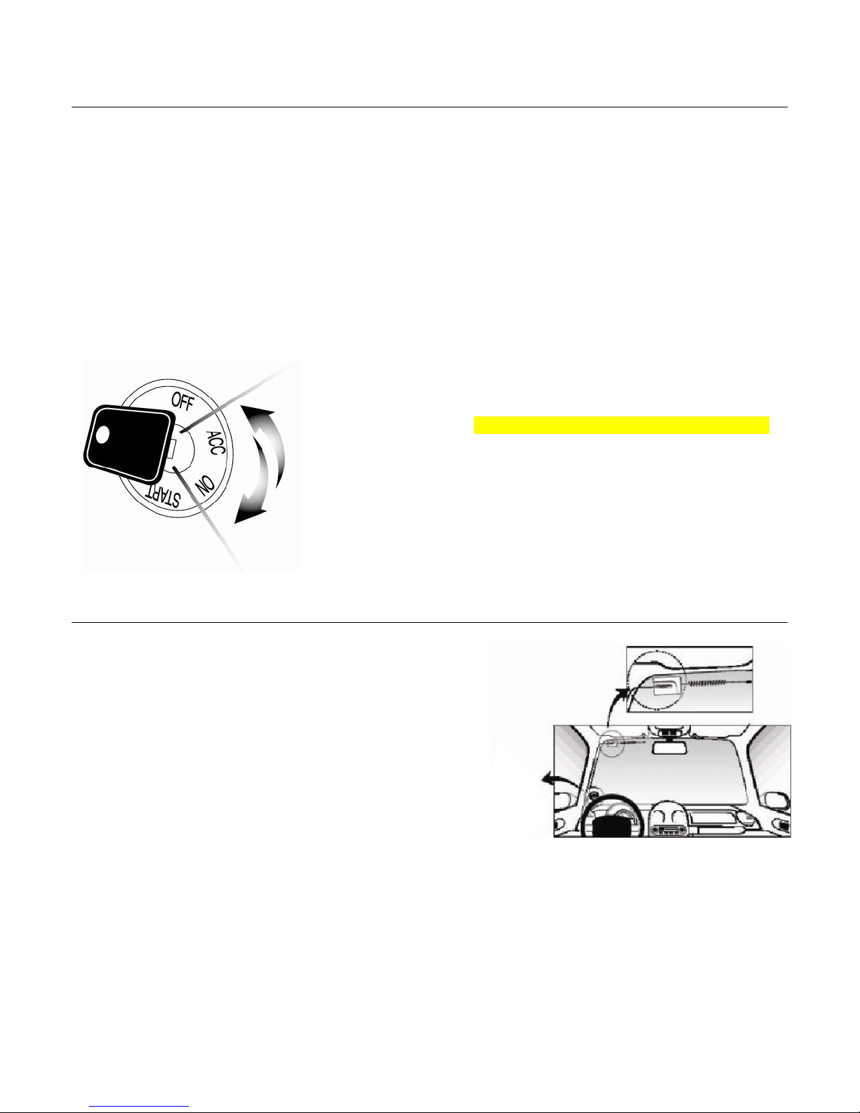
The two remotes are preprogrammed to the unit Page 5
This system is designed for ease of installation and the two included remotes are preprogrammed. In the
event you may need to program new remotes cycle the ignition ON / OFF five times within seven
seconds and tap the Lock button (half second) on the first remote, and then tap the Lock button (half
second) on the second remote.
This system is only compatible with Automatic transmission vehicles
Unlike other Firstech remote start systems the CM-900 is only compatible with Automatic transmission
vehicles. Manual transmissions are not supported by this unit.
New Valet Procedure Page 6
To place the system into Valet, you must hold the foot brake and cycle the ignition 5 times. To place the
system into Valet using the remote you must turn the ignition on and then tap the Lock and Trunk
buttons.
System comes in Tachless Sensing Mode
The CM-900 comes preprogrammed in Tachless Sensing Mode. You do not need to connect the
Yellow/Black Tach/Alternator sensing wire to remote start the vehicle.
Tach learning procedure Page 6
To Learn Tach:
STEP 1. Start the vehicle with the key and allow it to idle down
STEP 2. Press and hold the foot brake
STEP 3. While holding the foot brake, hold the remote start button on the remote for 3 seconds
One parking light flash indicates that the vehicle tachometer signal has been successfully learned. Three
parking light flashes indicate that the control module failed to learn the tachometer signal
New Option Menus Page 13
The new option menu differs completely from other Firstech systems. It is important to familiarize
yourself with these as it will save time in most applications.
Option Programmer (OP500) Page 16
Most options on this unit can be programmed with the remote(s) as well as the Option Programmer
(OP500). Please note the system must be disarmed before connecting the OP500. Otherwise, an
“ERROR” message will show on the display of your OP500.
Page 5
5
Remote Code Routine(s)
IMPORTANT: The remotes are preprogrammed to the control module. If you need to program the
remotes, follow the instructions below.
Programming the Remote
STEP 1: Activate Programming mode by turning the ignition key on and off (between the Acc & On
positions) five times within 10 seconds. The vehicle’s parking lights will flash once with the successful
completion of this step.
STEP 2: Within a second after cycling the ignition the 5th time, tap the Lock button on the remote for a
half second. The parking lights will flash once to confirm the transmitter has been coded.
Programming Multiple Remotes: After the confirmation flash given
in STEP 2, you can code additional remotes by tapping the Lock
button on the remote(s). The parking lights will flash once confirming
each additional remote. The CM-900 can store up to three remotes.
Exiting Programming: Programming is a timed sequence. The
parking lights will flash twice signaling the end of programming mode.
Placement and Use of Components
IMPORTANT: The placement and use of components are
critical to the performance of this system.
Antenna and Cable
Firstech antennas are calibrated for horizontal installation
at the top of the windshield. It does not have to be
mounted in the top left corner as shown to the left. The
cable that connects the antenna to the brain must be free
from any pinches or kinks. Installing the antenna in areas
other than the windshield may adversely affect the
effective transmitting distance of the remotes.
Hood Pin
The hood pin is an important safety feature that prevents the remote start from engaging while the hood
is open. This is also to prevent accidental injury in the event that the vehicle is in service.
Antenna
Page 6

6
Common Procedures
Valet Mode
When servicing or loaning your vehicle to others, your remote start system should be placed in Valet
Mode. Valet Mode prevents the system from remote starting and disables all alarm functions.
IMPORTANT: While in Valet mode the remote start will still lock and unlock power lock systems.
The system can be put into valet one of two ways:
1. Turn the vehicle’s key to the ignition “on” position and tap the Lock and Trunk buttons
simultaneously for a half second. The parking lights will flash once to confirm the system is in
Valet Mode. Repeat this process to take the system out of Valet Mode. Ignition does not have to
be on. Upon tapping the same buttons again the parking lights will flash twice to confirm the
system is out of Valet Mode.
2. You can put the system into Valet by holding the foot brake and then turning the
ignition key “on” and then “off” five times within 10 seconds. The parking lights will
flash once to confirm the system is in Valet Mode.
Jumper Settings
Caution: Jumper settings affect the polarity and use of certain outputs. If these jumpers are used
incorrectly, damage to the vehicle and control module may occur.
Jumper 1 (2nd Ignition / 2nd Starter / 2nd Accessory Relay)
This jumper determines the behavior of the large blue wire on Connector 1. This wire is powered by an
internal relay in the control module. In the default position the jumper is set to 2nd Ignition. 2nd Ignition is
common on GM and Toyota vehicles and will need powering. You can change the behavior of the wire to
act as a 2nd Starter or 2nd Accessory to power up those wires common on newer Toyotas and Nissans.
Tachless Sensing – Default Setting on Option 2-10
Tachless sensing is an alternative engine sensing mode. Tachless sensing does not require a
connection to the vehicle other than the main ignition harness. IMPORTANT: All wiring connections must
be made before attempting remote starting.
STEP 1: Connect all necessary wires.
STEP 2: Process complete – there is no further programming required other than adjusting crank time
when necessary (see below).
Adjusting Crank Time: To adjust the crank times, refer to Option 2-12. To ensure successful start, the
system will automatically add additional crank time to the 2nd and 3rd start attempts. In addition, there is
a built in “Smart Resting Mode”. Traditional tach sensing is highly recommended for colder climates.
Tach Sensing – Option 2-10 Setting 2
Tach sensing mode requires a connection made with the yellow/black wire on Connector 3. Firstech
recommends using an injector, coil or other tach source for tachometer sense. IMPORTANT: The tach
must be programmed before remote starting.
STEP 1: Start the vehicle with the key. Allow time for the engine to idle down.
Page 7

7
STEP 2: Test wire and make connection. With the vehicle off the wire should test 0 Volts AC. At idle the
tach wire should test between 1 to 5 Volts AC. As the vehicle RPM’s increase the voltage on the meter
will also increase. Always solder tach connections.
STEP 3: Learn tach. While the vehicle is at idle, hold the foot brake and press and hold the remote start
button on the remote control for 3 seconds.
The parking lights will flash once to confirm a good tach signal. The parking lights will flash three times to
indicate the tach did not learn. Two seconds following the three flashes, the number of parking light
flashes will indicate the cause of the error;
Alternator Sensing – Option 2-10 Setting 3
Alternator sense is an optional method the control module can use to verify if the engine is running. This
is different than tachless sensing so the yellow/black wire connection must be made. IMPORTANT: No
other option programming is required.
STEP 1: Change Option 2-10 to setting 3 - Alternator Sensing.
STEP 2: Test wire and make connection. The stator wire is found at the vehicle’s alternator. Change
your meter to DC before testing for this wire.
A. At rest, with the ignition off, the stator wire should test 0V DC.
B. Turn the ignition to the run position. The stator wire should now test between 1 – 6V DC.
C. Start the vehicle with the key. The stator wire should now test between 12 – 14V DC at idle.
STEP 3: Process complete – no further programming required.
Assumed Timed Crank – Option 2-10 Setting 4
Assumed Time Crank is the last feature of Option 2-10 for remote starting. This is intended for vehicles
with built-in anti-grind feature or that do not have a +12V Positive starter wire at the ignition harness. This
option will send a 3 second crank signal to the vehicle. This option can be used on vehicles with built in
anti-grind systems.
Automatic Transmission Remote Start Function
Hold the button for 3 seconds to remote start an automatic transmission vehicle. If you are in range
and the vehicle is ready to remote start, the parking lights will flash once.
If you are in range and the parking lights flash three times followed by a certain number after that, there
is a remote start error. Refer to the “remote start error diagnostic” table under the Troubleshooting
section of this manual for details.
Upon confirmation that your vehicle is running, the parking lights will light solid. The remote start run time
can be set for 3, 15, 25, or 45 minutes. Option 3-01 will adjust the remote start run time. This should be
Number of Parking Light
Flashes
Tach Error
1
Option 2-10 is not on setting 2
2
Key is in the off position
3
Bad tach signal. Find a different wire.
Page 8

8
set at the time of installation.
IMPORTANT: The vehicle’s key must be inserted into the ignition and turned to the “on” position prior to
driving your vehicle. If the foot brake is depressed prior to inserting the key and turning to the “on”
position, the vehicle will shut off.
Diesel Timer
The CM-900 module has a built in Diesel Timer to allow the vehicle’s glow plug wire to heat up. There
are multiple time settings on this unit, 3 to 99 seconds. This will allow the ignition to power up and then
crank once the time has expired and glow plugs have properly heated up.
Page 9
9
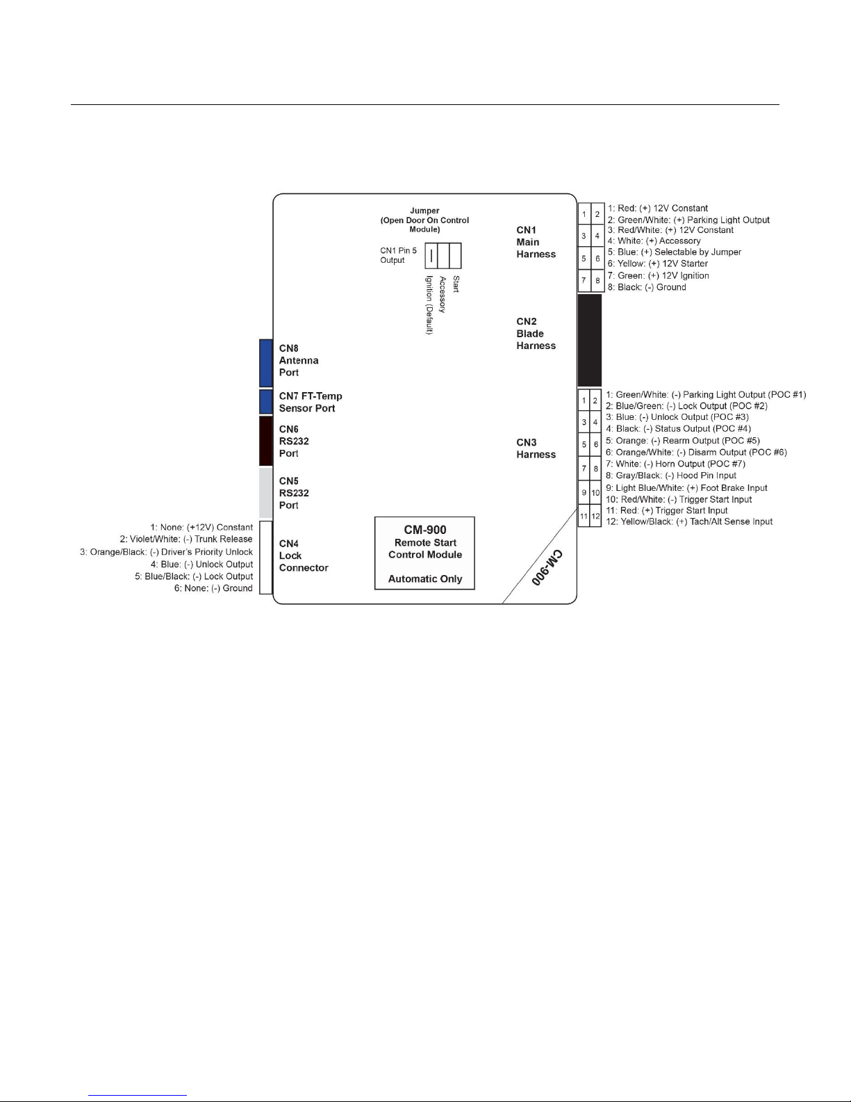
CM-900 Wiring Schematic (Remote Start)
Page 10

10
Connector 1 (CN1), 8-Pin Ignition Harness
Pin 1 Red - Constant 12V positive (+) power input. This wire must be connected. The proper vehicle
wire will test (+) 12V at all times - while the key is in the off position, the on position and during
crank.
Pin 2 Green/White – This is the positive (+) parking light wire that triggers when you lock and unlock
the doors and remote start the vehicle.
Pin 3 Red/White - Constant 12V positive (+) power input. This wire must be connected. The proper
vehicle wire will test (+) 12V at all times - while the key is in the off position, the on position and
during crank.
Pin 4 White - Accessory 12V positive (+) output. This wire must be connected to the vehicle accessory
/ HVAC blower motor wire. The proper wire will test 0V with the key in the off position, (+) 12V
while key is in the on position, 0V while cranking and back to (+) 12V when the key is returned to
the on position.
.
Pin 5 Blue - Positive 12V (+) output that powers up during remote start. The behavior of this wire is
selectable by a jumper inside the control module. By default this wire powers up as a 2nd Ignition
trigger. It is changeable to a 2nd Starter or 2nd Accessory.
Pin 6 Yellow - Starter 12V positive (+) output. This wire must be connected for remote start. The proper
wire will test 0V with the key in the off position, 0V while the key is in the on position and (+) 12V
during crank.
Pin 7 Green – Ignition 12V positive (+) output and input. This wire must be connected to the vehicles’
ignition for remote start and valet / remote programming. The proper wire will test 0V with the key
in the off position, 12 V (+) while the key is in the on position and 12V (+) during crank.
Pin 8 Black - Ground negative (-) input. This wire must be connected to the vehicle’s ground.
Connector 2 (CN2) Blade Connector and Cartridge
The CM-900 slot gives you the ability to use the Blade-AL and Blade-TB modules from Firstech
and ADS. With these modules you can virtually eliminate all wire connections between your
control module and bypass module. You only need to connect the main ignition harness and
needed from the Black 20 pin Blade connector that may be required according to the vehicle
specific Blade installation guide. For more information on how to program and wire the Blade,
please visit compustar.idatalink.com for the specific wiring diagram for that vehicle.
Page 11

11
Connector 3 (CN3), 12-Pin Harness
Pin 1 Green/White - [Programmable Output 1] Parking light 250mA negative (-) output. The proper wire
will test (-) when the parking light switch is in the on position. This wire can also be programmed
through Special Option Group #2 as 1 of 19 different outputs.
Pin 2 Blue/Green – [Programmable Output 2] Lock 250mA negative (-) output. This output can be used
to trigger the lock wire on the vehicle. This output can also be used to trigger a relay if you need a
positive (+) lock output. This wire can also be programmed through Special Option Group #2 as 1
of 19 different outputs.
Pin 3 Blue - [Programmable Output 3] Unlock 250mA negative (-) output. This output can be used to
trigger the unlock wire on the vehicle. This output can also be used to trigger a relay if you need a
positive (+) unlock output. This wire can also be programmed through Special Option Group #2
as 1 of 19 different outputs.
Pin 4 Black – [Programmable Output 4] Status/Ground while running 250mA negative (-) output. This is
an optional output that will provide a negative (-) output before the ignition cranks and stay on
throughout the remote start duration. This wire is most commonly used to trigger bypass /
transponder modules. This wire can also be programmed through Special Option Group #2 as 1
of 19 different outputs.
Pin 5 Orange – [Programmable Output 5] Factory Arm 250mA negative (-) output. This is an optional
output that will provide a (-) pulse during lock, after crank and again after the ignition shuts down.
This wire can also be programmed through Special Option Group #2 as 1 of 19 different outputs.
Pin 6 Orange/White – [Programmable Output 6] Factory Disarm 250mA negative (-) output. This is an
optional output that will provide a (-) pulse during unlock and prior to the ignition turning on. This
wire can also be programmed through Special Option Group #2 as 1 of 19 different outputs.
Pin 7 White - [Programmable Output 7] Horn honk 250mA negative (-) output. This is an optional
output that will pulse the factory horn. The proper wire will show ground (-) while the horn is
sounding. This wire can also be programmed through Special Option Group #2 as 1 of 19
different outputs.
Pin 8 Gray/Black – Hood Pin negative (-) input. This input is a safety shut down and alarm trigger. It
prevents the vehicle from remote starting while the hood is open and triggers the alarm if the
hood is opened while the alarm is armed. You can connect this wire to the hood pin supplied with
this kit, or to a wire in the vehicle that shows (-) only while the hood is open.
Pin 9 Light Blue/White - Brake 12V positive (+) input. This input must be connected as it provides a
shut down for the remote start. The proper wire will test (+) 12V while the foot brake is pressed.
Pin 10 Red/White – This wire requires a negative (-) pulse input for triggering the remote start
sequence. This wire allows you to use the CM-900 as a slave remote starter that can be
controlled by a factory OEM remote.
Page 12

12
Pin 11 Red - This wire requires a (+) pulse input for triggering the remote start sequence. This wire
allows you to use the CM-900 as a slave remote starter that can be controlled by a factory OEM
remote.
Pin 12 Yellow/Black - Engine sensing input. This wire is connected to the vehicle’s Tach or Alternator
wire and is required if you are not using the tachless sense setting. IMPORTANT: To change
engine-sensing modes, you must change Option 2-10:
Connector 4 (CN4), 6-Pin (Optional)
Pin 1 Not used
Pin 2 Violet/White - Trunk release 250mA negative (-) output. This is an optional output that will
release the trunk. System will unlock doors and disarm alarm prior to trunk release.
Pin 3 Orange/Black – 2nd Pulse Unlock wire. This wire is used to provide the customer with a driver’s
priority unlock feature with option 1-04. With the option on the unlock (blue) wire will pulse first
and then orange/black will pulse if the unlock button is pressed again within 3 seconds.
Pin 4 Blue - Unlock 250mA negative (-) output. This is an optional output that will provide a (-) pulse for
unlocking doors. System will unlock doors. IMPORTANT: You must use relays to reverse
polarity for (+) trigger door lock systems.
Pin 5 Blue/Black - Lock 250mA (-) negative output. This is an optional output that will provide a (-)
pulse for locking doors. System will lock doors. IMPORTANT: You must use relays to reverse
polarity for (+) trigger door lock systems.
Pin 6 Not used
Connector 5 (CN5), 4-Pin (Grey RS232 Port)
This port provides simple connectivity to DroneMobile devices and Fortin bypass modules.
Connector 6 (CN6), 4-Pin (Black RS232 Port)
This port provides simple connectivity to iDatalink bypass modules. This port supports 2-Way iDatalink
protocol.
Page 13

13
Connector 7 (CN7), 2-Pin (FT-Temp Sensor)
This port is for FT-Temp Sensors only. FT-Temp Sensor is formally known as Thermister.
Connector 8 (CN8), 4-Pin (Pre-wired Antenna Cable)
Pin 1 Yellow - RX input. This wire receives the signal from remote.
Pin 2 White - TX output. This wire transmits the signal to remote.
Pin 3 Red – Constant 12V positive (+) output.
Pin 4 Black – Negative (-) ground.
Page 14

14
Option Programming Tables
Feature
Default Setting - I
Optional
Setting - II
Optional
Setting - III
Optional
Setting - IV
1-01
Unlock Before, Lock After
Starting
OFF
ON
Lock After Start Only
Lock After Shutdown
Only
1-02
Lock / Unlock Pulse Duration
0.8 sec
2.5 sec
0.125 sec
3.5 sec
1-03
Driver's Priority Unlock
OFF
ON
1-04
Double Pulse Unlock
OFF
Unlock
Lock
Both Lock and Unlock
1-05
Rearm Output
First Lock, After Start
and After Shutdown
First Lock and After
Shutdown
After Start Only
After Shutdown Only
1-07
Unlock/Disarm With Trunk
Release
Unlock, Factory
Disarm, and Trunk
Release
Factory Disarm,
Trunk Release Only
Trunk Release Only
1-09
Ignition Controlled Door Locks*
OFF
ON
RPM Locks (Tach
Sensing Mode Only)
1-11
Ignition / Accessory Out Upon
Unlock
OFF
Ignition Pulse at
same time as Disarm
Accessory at same
time as Disarm
Ignition and
Accessory at same
time as Disarm
1-12
Arm and Disarm Remote
Paging by Datalink Module
ON
OFF
1-13
Double Pulse Disarm
Standard
Double Pulse
1-15
Trunk Output Timing
1 sec
2 sec
3 sec
4 sec
1-16
Horn Mute Control via Remote*
Disabled
Enabled
Feature
Default Setting - I
Optional
Setting - II
Optional
Setting - III
Optional
Setting - IV
2-01
Tach Sensing Type
Optimal Tach
Threshold
Previous Tach
Method
2-03
Diesel Timer
OFF
3-99 sec (12 sec
Default)
7 sec
GM Ignition Delay
2-04
Trigger Start
OFF
Single Pulse
Double Pulse
Triple Pulse
2-05
Cold or Hot Start With FT-
Temp Sensor*
OFF
Cold Start Only
Hot Start Only
Cold and Hot Start
2-06
Timer Start or Minimum Interval
Between Cold Starts
3 Hour (4 Minute
Runtime, Double for
Diesels)
2 Hour Repeat with
Cold Starting of 2-08
(Runtime 2-07)
Reservation (Runtime
2-07)
24 Hour Repeat With
Cold Starting of 2-08
(Runtime 2-07)
2-07
Remote Start Runtime
15 minutes
25 minutes
45 minutes
3 minutes
2-08
Temperature of Cold Starting
-10° C / 14° F
-20° C / -4° F
-5° C / 23° F
-15° C / 5° F
2-09
Temperature of Hot Starting
25° C / 77° F
30° C / 86° F
35° C / 95° F
40° C / 104° F
2-10
Engine Sensing
Tach
Alternator
No Connection (3.0
sec Start-Assume
Page 15

15
Tachless (Voltage
Sensing, Automatic
Transmission Only)
Running, Automatic
Transmission Only)
2-11
Advanced Tachless
OFF
ON
2-12
Minimum Crank Time
Standard
+0.2 Seconds to
Crank Time
+0.6 Sec to Crank
Time
Standard –
MIN(0.2sec)
2-13
Timer Mode
OFF
ON
Feature
Default Setting - I
Optional
Setting - II
Optional
Setting - III
Optional
Setting - IV
3-01
Parking Light Output
Constant Output
While Remote
Started
Flashing Output
While Remote
Started
Off While Remote
Started
Off During Lock and
Unlock Only
3-02
Confirmation Chrips
Medium (30 mS)
Short (15 mS)
Normal (60 mS)
3-04
Starter Kill Relay
Anti-Grind + Starter
Kill
Anti-Grind
Anti-Grind + Passive
Starter Kill
3-08
Horn Output
On Double Lock Only
On Lock and Unlock
On Lock, Unlock, and
Start
On Double Lock and
Start
3-10
Valet Mode
Key 5 times with Foot
Brake Trigger or
Remote (Lock +
Trunk) while Ignition
is On
Key 5 times with Foot
Brake Trigger or
Remote (Lock +
Trunk)
3-13
Defrost Temperature Control
Standard
Only Below 32
Degrees F / 0 C
Only Below 42
Degrees F/ 5.56 C
3-14
Defrost Output Time
0.5 sec pulse
3 min latch
7 min latch
Constant Output Until
Remote Start Shuts
Down
Feature
Default Setting - I
Optional
Setting - II
Optional
Setting - III
Optional
Setting - IV
4-01
Aux 1 Output
0.5 sec
Latch
0.5 sec Pulse +
Program
Program
4-02
Aux 2 Output
0.5 sec
Latch
0.5 sec Pulse +
Program
Program
4-03
Aux 1 Output Control
By Remote
Arm
Disarm
Negative (-) out w/ign
shutdown
4-04
Aux 2 Output Control
By Remote
Arm
Disarm
Start
4-05
Secure Auxiliary Output (1 and
2 Only)
ON
OFF
On While Armed
4-08
Aux 1 and Aux 2 Control for
iDatalink Modules (Sliding
Doors)
OFF
Unlock, Factory
Disarm and Sliding
Door Control
Factor Disarm and
Sliding Door Control
Only
4-10
(+) Trigger Start Input
(+) Trigger Start Input
(+) Ignition (Input
Only Installs)
(+) Keysense Input
(+) Glow Plug Input
4-11
RS232 Port (Grey Plug)
Protocol
Drone (Grey 4 Pin)
Fortin (Grey 4 Pin)
4-14
Low Battery Warning
OFF
ON (At 11.7 Volts)
Low Battery Start
(11.7 Volts)
Page 16

16
Special Option Group #1
Feature
Value (Seconds)
1
Diesel Timer
3-99 Seconds
2
Aux 1 Output Time
1-99 Seconds, "LA"
Latch, 1-15 Minutes
3
Aux 2 Output Time
1-99 Seconds, "LA"
Latch, 1-15 Minutes
Special Option Group #2
Feature
Value (Seconds)
1
POC #1 (Default : Light)
2nd LIGHT [ 1 ] 2nd START [2] 2nd IGN1 [3] 2nd ACC [4] STATUS [5] REARM [6]
DISARM [7] HORN [8] DOME LIGHT [9] AUX 1 [10] AUX 2 [11] DEFROST [17]
GWA [18] DEFROST 2 [21] LOCK [25] UNLOCK [26] PRIORITY UNLOCK [27]
TRUNK RELEASE [28] STARTER KILL [29]
2
POC #2 (Default : Lock)
3
POC #3 (Default : Unlock)
4
POC #4 (Default : Status)
5
POC #5 (Default : Rearm)
6
POC #6 (Default : Disarm)
7
POC #7 (Default : Horn)
IMPORTANT: System must be unlocked before you can set options with the OP500 or remotes.
*Once programmed, this feature requires activation from the remote. Please refer to the
remote user manual or the option description below.
Option Menu Descriptions
1-01 Unlock Before, Lock After Starting: FO1 - Off
FO2 - On:
Sends an unlock command as soon as the remote start sequence is triggered then send
a relock command as soon as the CM-900 has confirmed remote start success.
FO3 - Lock after start only:
Sends a lock command after the CM-900 has confirmed remote start
success.
FO4 - Lock after shutdown only:
will send a lock command only after the CM-900 has
successfully shut down.
Note: It will not provide an output if the CM-900 is shut down with an
emergency override input. (i.e. hood pin, or foot brake input)
1-02 Lock / Unlock Pulse Duration
: This does not affect the behavior of the factory arm output
(orange wire) or factory alarm disarm output (orange/white wire).
FO1 - 0.8 seconds:
(-) Negative lock and unlock output time.
Page 17

17
FO2 - 2.5 seconds:
(-) Negative lock and unlock output time.
FO3 - 0.125 seconds:
(-) Negative lock and unlock output time. This option may be helpful when
using lock/unlock to arm/disarm vehicles that may roll windows down with factory Arm/Disarm
wires when the standard output is too long.
FO4- 3.5 seconds: (-) Negative lock and unlock output time.
1-03
Driver’s Priority Unlock
:
FO1 - Off:
(default)
FO2 - On: This feature will allow the user to unlock the driver’s door first. If the unlock button is
pressed again within 4 seconds, the other doors will unlock. The driver’s door unlock must be
isolated from the other doors and use the blue (-) unlock. The Orange/Black (-) 2nd unlock (POC
setting) is used to provide unlock output to unlock all other doors.1-04
1-04 Double Pulse Unlock: FO1 - Off:
(default)
FO2 - Unlock:
This option will provide a double pulse output
only
for unlock each time the CM-900
executes the unlock command. (Length of output time will be based on feature 1-02 option
settings.)
FO3 - Lock:
This option will provide a double pulse lock output
only
for lock each time the CM-900
executes the lock command. (Length of output time will be based on feature 1-02 option settings.)
FO4 - Lock and unlock: This option will provide a double pulse lock output for both lock and
unlock each time the CM-900 executes lock or unlock commands. (Length of output time will be
based on feature 1-02 option settings.)
1-05 Rearm Output: FO1 - After start, after shutdown, after first lock:
This option triggers the FAA
after every successful remote start, every successful remote start shut down, and with every first
lock command. (First lock command is the first arm/lock command sent after the CM-900 has been
disarmed or unlocked.)
FO2 - After shut down only and first lock:
This option triggers the FAA after every successful
remote start shut down, and with every first lock command. (First lock command is the first
arm/lock command sent after the CM-900 has been disarmed or unlocked.)
FO3 - After Start only:
This option triggers FAA after every successful remote start.
FO4 - After shutdown only:
This option triggers the FAA after every successful remote start shut
1-07 Unlock/Disarm With Trunk Release: FO1 - Unlock, Factory Alarm Disarm (FAD) trunk
releas:
This option will send unlock and FAD outputs prior to sending the Trunk release output.
This applies to analog and data to data situations.
FO2 - Factory Alarm Disarm (FAD) with trunk release:
This option will send the FAD output
prior to sending the trunk release output. This applies to analog and data to data situations.
FO3 - Trunk release only: This option will only send the trunk release output when triggered. This
applies to analog and data to data situations.
1-09 Ignition Controlled Locks
: When FO 2-4 are selected, the user can activate the “drive lock” or
ignition controlled door locking feature using a Firstech remote or Drone.
(Please check specific
remote user’s manual for steps to activate Drive lock.)
FO1 - Off:
(default)
FO2 - On:
This option (when activated with the Firstech remote or Drone) will provide a door lock
output when the foot brake is applied or 12 Volts is applied to the foot brake input on the CM-900.
Page 18

18
The CM-900 will also provide a door unlock output as soon as the key is turned off or 12v ignition
is removed from the CM-900.
FO3 - RPM locking: (Tach input is required for this option to operate properly.) This option
will provide a door lock output at approximately 20% RPM over the programmed idle tach output.
(i.e. program tach at 1000 rpm and doors will lock at a sustained 1200 rpm when moving.) The
CM-900 will also provide a door unlock output as soon as the key is turned off or 12v ignition is
removed from the CM-900.
1-11 Ignition + Accessory Pulse with Disarm: FO1 - Off:
(default)
FO2 - Ignition (+) and (-) pulse output with disarm:
This option will pulse both (+) and (-) ignition
wires upon unlock/disarm.
Most new Ford vehicles require ignition pulsed + immobilizer with
unlock to disarm the factory alarm.
FO3 - Accessory (+) and (-) pulse output with disarm:
This option will pulse both (+) and (-)
accessory wires upon unlock/disarm.
FO4 - Ignition (+) and (-) pulse and Accessory (+) and (-) pulse output with disarm: This
option will pulse both (+) and (-) ignition and accessory wires upon unlock/disarm. Some new Ford
vehicles require ignition and accessory pulsed + immobilizer with unlock to disarm the
factory alarm. Important: Also used in cases where the vehicle’s radio may turn on and stay on
until the door is opened when accessory is pulsed.
1-12 Arm and Disarm Remote Paging by Datalink Module
: This feature disables the arming,
disarming, and remote start confirmation updates to any Firstech 2 Way LCD when using an OEM
remote.
FO1 - On:
(default)
FO2 - Off: This feature disables the page back update to the 2 Way Firstech remote when your
interface module provides OEM remote status updates to the CM-900.
1-13 Double Pulse Disarm
: This feature enables the FAD output. It will pulse 2 times with a single
disarm command.
FO1 - Off (default):
Standard single pulse output on the FAD wire.
(orange/white by default)
FO2 - On: This feature will generate a double pulse output on the FAD wire. (orange/white by
default)
1-15 Trunk Output Timing
: This feature determines the length of output time for the (+) or (-) analog
trunk release wire.
FO1 - 1 Second:
(default) Will provide a 250mA (-) negative output for 1 second on any POC that
is programmed for trunk release or setting 28.
FO2 - 2 Seconds:
FO1- 1 Second: (default) will provide a 250mA (-) negative output for 2 seconds
on any POC that is programmed for trunk release or setting 28.
FO3 - 3 Seconds:
FO1- 1 Second: (default) will provide a 250mA (-) negative output for 3 seconds
on any POC that is programmed for trunk release or setting 28.
FO4 - 4 Seconds: FO1- 1 Second: (default) will provide a 250mA (-) negative output for 4 seconds
on any POC that is programmed for trunk release or setting 28.
1-16 Siren/Horn mute control
: this feature allows the installer to enable or disable the siren/horn mute
control. The mute feature will silence the siren or horn during arm, disarm, and start from the
Firstech remote.
FO1 - Disabled:
(default) will not allow for the Firstech remote to mute the siren or horn output.
Page 19

19
FO2 - Enabled:
this feature will allow the end user to activate or deactivate the siren or horn mute
control.
2-01 Tach Sensing Method:
This feature will determine the point at which the CM-900 releases the
starter based on the sampled tach method.
FO1 - Optimal Tach reading:
This option will allow the CM-900 to sample the tach signal several
times during tach programming and select the optimal tach voltage at which to release the starter.
FO2 - Previous tach reading: This option will set the CM-900 to record the idle voltage which it is
being programmed. The CM-900 will release the starter once the idle tach voltage is met.
2-03 Diesel Timer: Note: OP500 required to adjust time from any of the default settings,
will show up as DISL on the top line of text when option 2 or 3 are enabled.
This feature
provides a timed alternative solution to a hard wired glow plug input to enable the CM-900 to wait
to start.
FO1 - Wire:
(default) This option will allow the CM-900 to read input on brown/white wire. (PIC3) It
may be connected to a wait to start indicator on a diesel vehicle. When the CM-900 sees (-)
negative input, it will delay the crank output for 99 seconds or until negative signal has been
removed.
FO2 - Program (3-99 seconds):
default setting is 12 seconds. This option allows the installer to
adjust the time in 1 second increments that the CM-900 waits before cranking the starter.
FO3 - 7 seconds:
This option offers a fixed 7 second delay before providing starter output.
FO4 - GM Ignition delay: This option is designed to delay the ignition output 250mS during the
remote start procedure. This allows for the accessory to output first, then ignition, to simulate
normal key starting. There are some vehicle models that may require this additional delay in order
for it to remote start properly.
2-04 Trigger Start:
This feature changes the number of pulsed inputs (min of 60mS per pulse) on the
trigger start input wires. (red or red/white wires CN3).
Note: If option 3 is selected and OEM
remote control feature is available through data, the Control Module will accept 3 OEM lock
commands to activate the start sequence. FO1 - Off:
(default)
FO2 - Single pulse:
This option will trigger the remote start sequence with a single pulsed input to
the trigger start wire. This is ideal when adding accessories that can trigger the CM-900.
FO3 - Double pulse:
This option will trigger the remote start sequence with 2 pulses to the trigger
start input wire. This can be used when integrating with an OEM keyless entry remote.
FO4 - Triple pulse: This option will trigger the start sequence with 3 pulses to the trigger start
input wire. This is ideal when trying to integrate the OEM keyless entry remote. Note: this option
will also allow the CM-900 to accept a 3 pulse input from OEM remote commands through data.
2-05 Cold or Hot Start: Note: the Firstech Thermister (FT-TEMP SENSOR) temp sensor must be
connected to the CM-900 in order to use these options.
This feature turns on the cold/hot
Timer start features.
FO1 - Off:
(default)
FO2 - Cold start:
This option enables the thermister when using Timer Start Mode. It will start the
car at the preset cold temperature (see feature 2-08) according to the selected timer start option
(see feature 2-06)
FO3 - Hot Start: This option enables the thermister when using Timer Start Mode. It will start the
car at the preset hot temperature (see feature 2-09) according to the selected timer start option.
(see feature 2-06)
Page 20

20
2-06 Timer Start:
This feature is designed to allow the user to have the CM-900 automatically remote
start at the end of a selected timed cycle. It also be controlled by the thermister so it will start at a
specified temperature at the end of the timed cycle.
FO1 - 3 hour cycle:
(4 minute runtime, 8 minute runtime for diesel) Once Timer Mode is enabled
(see feature 2-13) the CM-900 will wait 3 hours, remote start and run for 4 minutes unless the cold
start feature is enabled. If this is the case, the CM-900 will check the temperature once every 3
hours. If it is at or below the selected temperature, (see feature 2-08) it will start and run for 4
minutes. The same procedure will apply to the hot start feature. If there is any interaction with the
CM-900 after timer mode has been activated using the Firstech remote or accessory, timer mode
will be cancelled and must be re-started in order to start a new timed cycle.
FO2 - 2 hour repeat with cold starting:
(runtime based on feature 2-07 option setting and cold
start setting based on feature 2-08) Note: 2 way LCD remote required. This option is designed to
monitor the temperature 2 hrs. After timer mode is set and start if it is at or below the preset cold
start temperature (see feature 2-08). This process will continue until the user manually starts or
remote starts the vehicle.
FO3 - Reserve runtime:
(runtime based on feature 2-07 option setting) Note: 2 way LCD remote
required. This option will allow the user to set a predetermined time to remote start on the 2 way
LCD remote. Once the timer mode is activated it will start the countdown timer on the CM-900
based on the difference of time between what the remote clock is set to and the timer mode time is
set to. I.e. remote time reads 7:00pm and timer mode time is set to 7:00 am the CM-900 will
activate the timer mode to go for 12hours before it starts. Note: it is important that the remote time
is as accurate as possible when activating the timer mode to ensure that it will start at the desired
time. If there is any interaction with the vehicle or system after timer mode has been activated it will
cancel the timer.
FO4 - 24 hour repeat with cold starting: (runtime based on feature 2-07 option setting and cold
start setting based on feature 2-08) Note: 2 way LCD remote required. This option is designed to
monitor the temperature 24 hrs. After timer mode is set and start if it is at or below the preset cold
start temperature (see feature 2-08). This process will continue until the user manually starts or
remote starts the vehicle.
2-07 Remote Start Runtime:
This feature consists of four different settings for the remote start run time.
FO1 - 15 minutes
(default)
FO2 - 25 minutes
FO3 - 45 minutes
FO4 - 3 minute runtime:
to comply with any local idle laws prohibiting extended idle times.
2-08 Cold start Temperature:
This feature allows the user 4 different temperature settings for cold start
operation
FO1 - 14°F/-10°C:
will activate the start sequence at the end of the time cycle (set by
feature 2-06 option setting) if temperature is at or below this temperature.
FO2 - -4°F/-20°C:
will activate the start sequence at the end of the time cycle (set by feature 2-06
option setting) if temperature is at or below this temperature.
FO3 - 23° F/-5° C:
will activate the start sequence at the end of the time cycle (set by feature 2-06
option setting) if temperature is at or below this temperature.
FO4 - 5° F/-15° C: will activate the start sequence at the end of the time cycle (set by feature 2-06
option setting) if temperature is at or below this temperature.
2-09 Hot Start Temperature:
This feature allows the user 4 different settings for hot start operation
Page 21

21
FO1 - 77° F/25° C:
will activate the start sequence at the end of the time cycle (set by feature 2-06
option setting) if temperature is at or above this temperature.
FO2 - 86° F/30° C:
will activate the start sequence at the end of the time cycle (set by feature 2-06
option setting) if temperature is at or above this temperature.
FO3 - 95° F/35° C:
will activate the start sequence at the end of the time cycle (set by feature 2-06
option setting) if temperature is at or above this temperature.
FO4 - 104° F/40° C: will activate the start sequence at the end of the time cycle (set by feature 206
option setting) if temperature is at or above this temperature.
2-10 Engine Sensing:
This feature provides 4 options for engine sensing methods. Every CM-900 is
shipped in manual transmission mode. Tach sensing is our default engine sense option.
FO1 - Tach:
This option uses a hard wired input (yellow/black CN3 gray connector) to read the
vehicles RPM’s in order to release the starter during the remote start process and determine that
the engine is running.
FO2 - Alternator:
This option uses the hardwired tach input (yellow/black CN3 gray connector) to
read the voltage output from the vehicles stator wire in order to release the starter during the
remote start process and determine that the engine is running. Note: with late model computer
controlled alternators, the peak charging voltage mat not be reached for several seconds after the
vehicle is running. This may make this option inconsistent when the battery is low or very cold.
FO3 - No connection Tachless sensing:
(aka “voltage sensing”) Note: can only be used with
automatic transmission. This option uses the voltage readings on the power input at the main CN1
connector to monitor the voltage before, during, and after crank, to determine when to release the
starter and consider the vehicle running. Note: with late model computer controlled alternators, the
peak charging voltage mat not be reached for several seconds after the vehicle is running. This
may make this option inconsistent when the battery is low or very cold.
FO4 - No connection Assumed running: (aka engine sense off) Note: can only be used with
automatic transmission. This option provides a 3 second starter output, leave the rest of the CM900 ignition and accessory outputs on and consider the vehicle running. Note: This is a good
option for (PTS) Push To Start applications and Hybrid vehicles (except manual transmission).
2-11 Advanced Tachless:
This feature when used in conjunction with feature 2-10 option 3 will provide
an enhanced Tachless engine sensing mode.
FO1 - Off:
(default)
FO2 - On:
this option will enable the advanced algorithm to monitor battery voltage before, during,
and after crank to allow the CM-900 to release the starter and consider the vehicle running. This
option is better suited for late model computer controlled vehicles or older vehicles with poor
battery conditions.
Note:
feature 2-10 must be set to option 3 in order for it to work properly. If
there is tach signal input to the CM-900 either analog or data interface module, this option will not
operate consistently.
2-12 Crank Time:
This feature allows the user to add or remove crank time to the selected option for
feature 2-10 (engine sense).
FO1 - Standard:
(default crank time no change).
FO2 - +200mS:
To standard crank time of option selected on feature 2-10.
FO3 - +600mS:
Adds 600 milliseconds to standard crank time of option selected on feature 2-10.
FO4 - (-)200mS:
releases the starter output 200 Milliseconds earlier than standard crank time of
option selected on feature 2-10.
Page 22

22
2-13 Timer Mode:
(Note: Must be set to on in order to operate timer mode).This feature enables the
user to activate and deactivate Timer Mode (see option 2-06) using the Firstech remote or
accessory (see the user manual for that remote for instructions).
FO1 - Off:
(default)
FO2 - On: user must still activate timer mode using their Firstech remote or accessory.
3-01 Parking Lights while Remote Started:
This feature changes the parking light behavior during
remote start.
FO1 - Constant output:
This option will keep the parking light output (+ and -) on steady
throughout the entire runtime (runtime based on feature 2-07 selection)
FO2 - Flashing output:
This option will flash the parking light output (+ and -) throughout the
entire runtime (runtime based on feature 2-07 selection)
FO3 - Off:
This option turns the parking lights off while the vehicle is remote started.
FO4 - Off with lock and unlock only:
This feature is designed to eliminate redundant parking light
flash with lock/unlock when interface module flashes the parking lights controlling the Factory
security.
3-02 Confirmation Chirps:
This feature will allow the user to select a shorter siren output time to
simulate a quieter arm/disarm/start output.
FO1 - 30mS:
This is a 30 milliseconds siren output with arm, disarm, and start confirmation chirps.
It will produce a “medium” volume sound. (Softer than the standard 60mS output)
FO2 - 15mS:
This is a 15 millisecond siren output with arm, disarm, and start confirmation chirps. It
will produce a “short” or quiet volume of sound. (Significantly softer than the standard 60mS
output)
FO3 - 60mS: This is a standard 60 millisecond siren output with arm, disarm, and start
confirmation chirps.
3-04 Starter-Kill:
This option determines the operation of the GWA wire (Any POC on CN3)
Must be
programmed on Special Option Group #2.
FO1 - Anti grind + Starter interrupt:
this option will allow the GWA to provide a negative output
when the system is armed or remote started. This will enable a starter interrupt to prevent the
vehicle from being started with the key when in an armed state.
FO2 - Anti Grind only:
This option will allow GWA to provide a negative output when the system
is armed. This will enable starter interrupt and prevent the user from grinding the starter during the
takeover procedure.
FO3 - Anti Grind and passive starter interrupt: This option will allow for GWA to provide a
negative output when the system is remote started or the passive starter interrupt is engaged. This
will prevent the user from grinding the starter during the takeover procedure and enable starter
interrupt 45 seconds after the ignition has been turned off.
3-08 Horn Output:
This feature controls the horn output behavior during Arm, Disarm, and Remote
Start. (POC setting #8)
FO1 - On double lock only:
(default) this option is designed to simulate a factory keyless entry
system by providing a horn output pulse (based on the option selection of feature 3-02) each time
the lock command is sent a second time within 8 seconds of the first lock command.
Page 23

23
FO2 - On lock and Unlock only:
this option will provide a horn output pulse (based on the option
selection of feature 3-02) with each lock or unlock confirmation.
FO3 - On lock, Unlock, and Start:
this option will provide a horn output pulse (based on the
option selection of feature 3-02) with each lock, unlock, remote start command and remote started
confirmation.
FO4 - On double lock and Start:
this option is designed to simulate a factory keyless entry
system by providing a horn output pulse (based on the option selection of feature 3-02) each time
the lock command is sent a second time within 8 seconds of the first. It will also provide a horn
output pulse with remote start command and remote start confirmation.
3-10 Valet Mode:
This feature will change the enter/exit valet mode procedure based on the option
selected.
FO1 - Key 5 times with Foot Brake Trigger or Remote (Lock + Trunk) while Ignition is on:
This option allows the user to enter valet mode using either method described.
Note: the user
may exit valet mode with their Firstech remote (please check users guide for each remote
for valet mode exit procedure), or with the key to ignition or “on” position and press the
foot brake 10 times within 10 seconds.
FO2 - Key 5 times with Foot Brake Trigger or Remote (Lock + Trunk): This option allows the
user to enter valet mode using either method described. Note: the user may exit valet mode with
their Firstech remote (please check users guide for each remote for valet mode exit
procedure), or with the key to ignition or “on” position and press the foot brake 10 times
within 10 seconds.
3-13 Defrost Output Temp Control:
This feature will determine the temperature at which the CM-900
will provide an output on any POC programmed with setting 17 or 21 (defrost and defrost 2).
FO1 - Standard:
(Default) this option will provide an output (length of output based on feature 3-13
option settings) on any POC programmed with setting 17 (defrost) or 21 (defrost 2) every time with
remote start confirmation.
FO2 - 32°F:
(FT-TEMP SENSOR required) this option will provide an output on any POC
programmed with setting 17 (defrost) or 21 (defrost 2) with remote start confirmation on. This will
happen if the temp reading is at or below 32°F. (Length of output based on feature 3-13 option
settings)
FO3 - 42°F: (FT-TEMP SENSOR required) this option will provide an output on any POC
programmed with setting 17 (defrost) or 21 (defrost 2) with remote start confirmation on. This will
happen if the temp reading is at or below 42°F. (Length of output based on feature 3-13 option
settings)
3-14 Defrost Output Timing:
This feature controls the output timing of POC setting 17, defrost.
Note:
POC setting 21 defrost 2 is has a fixed pulsed output and is NOT affected by this feature.
FO1 - 500mS Pulse:
This option will provide a 500 Millisecond pulsed output on any POC
programmed with setting 17 (Defrost) with timing based off of feature 3-12 option setting.
FO2 - 3 minute latched:
This option will provide a 3 minute latched output on any POC
programmed with setting 17 (Defrost) with timing based off of feature 3-12 option setting. (This
would be good for any rear view mirror defrost that may need a short latched output time.)
FO3 - 7 minute latched:
This option will provide a 7 minute latched output on any POC
programmed with setting 17 (Defrost) with timing based off of feature 3-12 option settings. (This
Page 24

24
would be good for many front, rear, or rear view mirror defrost functions that may need a longer
latched output time.)
FO4 - Latched for Entire Runtime: (Remote start runtime based off of feature 2-07 option setting)
This feature will provide a latched output for the entire remote start runtime on any POC
programmed with setting 17 (defrost) with timing based off of feature 3-12 option settings. Caution:
make sure not to latch rear defrost functions on for too long as it may cause damage to the heating
elements in the window.
4-01 Aux 1 Output:
This feature determines the duration of the auxiliary 1 output. (Option 4 allows the
output duration to be set for a specific length of time 1-99 sec. and 1-15 min (with OP500 update
only)
(Specific time setting only available when using the OP500)
FO1 - 500mS:
This option will provide a (-) negative output for 500 milliseconds (Half second)
output on any POC programmed with setting 10 (AUX 1)
FO2 - Latched:
This option will provide a latched (-) negative output on any POC programmed
with setting 10 (AUX 1).
Note: This will stay latched until AUX 1 command is sent again to
shut it off.
FO3 - 500mS pulse + programmable timed output:
This option will provide a (-) negative output
for 500 milliseconds (0.5 seconds) output on any POC programmed with setting 10 (AUX 1). It will
pause for 250 milliseconds then provide a timed output (based off of feature 4-01 option 4). Note:
in order to program the timed output the user must change feature 4-01 to option 4, then adjust
AU1 (AUX programmable output time) to desired time. To complete the programming steps feature
4-01 must be changed to option 3. I.e. 0.5 second pulse…pause…10 second pulse, this option can
be used to roll windows up or down on a vehicle that requires a similar action using the driver’s
door key cylinder.
FO4 - Program:
This option allow the AUX output time to be programmed for a duration between
1-99 seconds. Note: with an OP500 update there will be additional time duration between 1-15
minutes available.
4-02 Aux 2 Output:
This feature determines the duration of the auxiliary 2 output. (Option 4 allows the
output duration to be set for a specific length of time 1-99 sec. and 1-15 min (with OP500 update
only) only available when using the OP500)
FO1 - 500mS:
This option will provide a (-) negative output for 500 milliseconds (0.5 seconds)
output on any POC programmed with setting 11 (AUX 2)
FO2 - Latched: This option will provide a latched (-) negative output on any POC programmed
with setting 11 (AUX 2). Note: This latched output will reset when ignition is turned on.
FO3 - 500mS pulse + programmable timed output:
This option will provide a (-) negative output
for 500 milliseconds (0.5 seconds) output on any POC programmed with setting 11 (AUX 2). It will
pause for 250 milliseconds then provide a timed output (based off of feature 4-02 option 4). Note:
in order to program the timed output the user must change feature 4-02 to option 4, then adjust
AU2 (AUX programmable output time) to desired time. To complete the programming steps feature
4-01 must be changed to option 3. (i.e. half second pulse…pause…10 second pulse)
This option
can be used to roll windows up or down on a vehicle that requires a similar action using the
driver’s door key cylinder.
FO4 - Program:
This option allows the AUX output time to be programmed for a duration between
1-99 seconds.
Note: The OP500 must be updated for additional time duration settings. (1-15
minutes available)
Page 25

25
4-03 Aux 1 Output Control:
This feature allows the user to configure the method of which Auxiliary 1
can be activated.
FO1 - Remote:
(default) This option allows AUX 1 (output time based on feature 4-01) to be
triggered by any 4 button Firstech remote or drone.
FO2 - With Arm:
This option will trigger AUX 1 (output time based on feature 4-01) any time the
CM-900 is locked/armed the first time (i.e. if you send a second lock/arm command it will not
trigger again)
FO3 - With Disarm:
This option will trigger AUX 1 (output time based on feature 4-01) any time the
CM-900 is unlocked/disarmed.
Note: the system has to be in the armed state when disarming
in order to trigger AUX 1. (I.e. if the vehicle is already in the unlocked/disarmed state and
you send a second unlock/disarm command it will not trigger the output)
FO4 - With ignition removed:
This option will trigger AUX 1 (output time based on feature 4-01)
as soon as Ignition input is removed from the CM-900. (I.e. this feature can be used with a manual
transmission vehicle to open the door input circuit on the CM-900 for a set period of time when
reservation mode is complete in order to prevent the dome light from cancelling reservation mode.)
4-04 Aux 2 Output Control:
This feature allows the user to configure the method of which Auxiliary 2
can be activated.
FO1 - Remote:
(default) This option allows AUX 2 (output time based on feature 4-02) to be
triggered by any 4 button Firstech remote or drone.
FO2 - With Arm:
this option will trigger AUX 2 (output time based on feature 4-02) any time the
CM-900 is locked/armed the first time (I.e. if you send a second lock/arm command it will not
trigger again)
FO3 - With Disarm:
This option will trigger AUX 2 (output time based on feature 4-02) any time the
CM-900 is unlocked/disarmed. Note: the system has to be in the armed state when disarming in
order to trigger AUX 1. (I.e. if the vehicle is already in the unlocked/disarmed state and you send a
second unlock/disarm command it will not trigger the output)
FO4 - With Start:
This option will trigger the AUX 2 (output time based on feature 4-02) when the
remote start sequence is initiated. It will trigger at the same time as GWR (ground when running)
4-05 Secure Aux Output:
This feature is designed to prevent accidental activation of the AUX outputs
by requiring an additional step when using any 4 button or 2 way LCD Firstech remote.
FO1- On:
(default) this option will require the user to perform an additional step before activating
AUX output using any Firstech 4 button or 2 way LCD remote (2way remotes with Roman numeral
buttons will require a 0.5 second tap of button IV before activating any of the AUX outputs.2Way
LCD remotes with lock/unlock/trunk/start icons on the buttons use the start button for the same.
1way remotes require the user to hold trunk + start buttons for 3 seconds before activating AUX
outputs.)
FO2- Off:
This option will disable the additional step required by the user to activate the AUX
outputs.
*NEW* FO3- On while armed:
This feature will only require the user to perform the additional
override step to activate Aux outputs
ONLY WHEN
the CM-900 is
ARMED
. While the system is
disarmed or unlocked this step is not required.
Page 26

26
4-08 Sliding Door Control For Datalink:
(must be enabled to allow data to data sliding door control)
This feature will provide an Unlock or Factory Alarm Disarm (FAD) output when triggering the AUX
control using iDatalink Modules (Sliding Doors)
FO1 - Off:
(default) This option does not provide an unlock or a FAD output when activating AUX
output control using the iDatalink modules.
FO2 - Unlock and FAD:
This option will provide unlock and a FAD output when activating AUX
output control using iDatalink modules.
FO3 - FAD only:
This option will only provide a FAD (factory alarm disarm) output when activating
AUX output control using iDatalink modules.
4-10 Trigger Start Input:
this feature will determine the input function of the positive red wire on CN3.
FO1 - Trigger Start Input:
This option will enable the (+) trigger start wire to be used as a trigger
for activating the remote start function using a (+) pulse input on the red wire CN3
FO2 - Closed Loop:
This option will enable the (+) trigger start wire to be used as a positive
Ignition Input Wire. This input should see +12V when the key is on and whenever it is running. This
wire does not send a +12V output from the control module.
FO3 - (+) Keysense Input:
this option will operate as a key sense INPUT to the CM. When used
with manual transmission, keysense input will keep the CM from completing reservation mode as
long as the input is present. In addition the keysense input will keep the system from passively
arming or EZGO proximity locking as long as the input is present.
FO4 - (+) Glow Plug Input:
This option will let you use this wire as a wait to start input. It requires
a (+) trigger from the vehicle’s glow plug wire.
4-11 Grey UART Port Protocol:
This feature will determine the communication protocol of the gray
UART port.
FO1 - Drone:
(default) This option sets the grey UART port to communicate using the Drone data
protocol.
FO2 - Fortin: This option sets the grey UART port to communicate using the Fortin data
protocol. Note: there is no longer an “auto detect” feature with the Fortin protocol it must be
changed manually.
4-14 Low Battery:
This feature offers low battery options to help alert the user of a low battery in the
vehicle.
FO1 - Off:
(default) This option does not provide a low battery indication.
FO2 - On:
This option will provide an alert to any Firstech 2 Way LCD remote or Drone when the
vehicle’s battery voltage (at the CM-900 power connector) drops to 11.7volts.
Note: the Firstech 2
way LCD remote must be within range of the vehicle to receive the low battery alert and this
option must be set in order to receive low battery alerts to Drone.
FO3 - On + Start: This option will provide an alert to any Firstech 2 Way LCD remote or Drone
when the vehicles battery voltage (at the CM-900 power connector) drops to 11.7 volts. In addition
to the alert the user can active the Timer mode (please refer to this manual for timer mode feature
description) to enable the low battery start function. Once the timer mode is active the CM-900 will
adhere to the timer mode feature options selected but also monitor the vehicle battery voltage
which will override the timer mode and start at 11.7 volts.
Special Option Groups 1 and 2
Page 27

27
IMPORTANT: The OP500 is required to change settings in Special Option Groups 1 and 2.
Special Option Group 1
FO1- Diesel Timer:
(Option 2-03 must first be set to setting 2.) This special option allows a
specific wait to start time (in seconds) to be programmed. This prevents the need for a timer relay
and eliminates a connection to the “wait to start” wire.
FO2 - Aux 1 Output Timing: (Option 4-01 must first be set to setting 4.) This special option allows
a specific output duration for Aux 1 to be programmed 1-99 seconds. Note with OP500 update,
latched output time 1-15 minutes are available for programming in addition to the standard
1-99 seconds.
FO3 - Aux 2 Output Timing:
(Option 4-02 must first be set to setting 4.) This special option allows
a specific output duration for Aux 2 to be programmed 1-99 seconds.
Note with OP500 update,
latched output time 1-15 minutes are available for programming in addition to the standard
1-99 seconds.
Special Option Group 2
This special option group allows you to determine the output type of the POC wire. For example, if you
want to set POC #5 (default setting status out) to Aux 1, you will need change special option 5 to number
10. This must be done with the OP500.
POC 1 – Green/White • Negative Parking Light Output:
(default setting) This channel will
provide a 250mA (-) negative output when the CM-900 is armed
(function also POC setting 1)
POC 2 – Blue/Green • Lock:
(default setting) This channel will provide a 250mA output with the
lock/arm command.
(function also POC setting 25)
POC 3 - Blue • Unlock:
(default setting) This channel will provide a 250mA output with the
unlock/disarm command.
(function also POC setting 26)
POC 4 - Black • GWR (ground when running aka status output):
(default setting) This channel
will provide a 250mA output with the remote start activation command and continue to provide
output until 100mS after the remote start process has shut own.
(function also POC setting 5)
POC 5 - Orange • FAA (Factory Alarm Ream):
(default setting) This channel will provide a
250mA output with the lock/arm command. Note: the CM-900 will provide this output approx.
100mS before the unlock output.
(function also POC setting 6)
POC 6 - Orange/White • FAD (Factory Alarm Disarm):
(default setting) This channel will provide
a 250mA output with the unlock/disarm command.
Note: the CM-900 will provide this output
approx. 100mS before the unlock output. (function also POC setting 7)
POC 7 - White • Horn:
(default setting) This channel will provide a 250mA output when Horn is
triggered.
(function also POC setting 8)
Page 28

28
Option Programming
How to Program Options
There are two ways to set options on the CM-900 control modules. You can use the FT-OP500 or most
Firstech remotes. The remotes include 4 or 5 button 1 and 2 Way remotes.
Option Programming Using the FT-OP500
The OP500 can be used to change anything in the Option Tables. It is required to change settings in the
Special Option Group.
STEP 1: Make sure system is unlocked/disarmed.
Connect the antenna cable to the 4 or 6 pin port on
the top of the OP500. Once connected, the OP500 will power up as long as CN1 on the control module is
connected properly.
STEP 2:
Use the left or right arrow keys on the OP500 to select option. Use the up or down arrow
buttons to select the option setting. “1” is the default setting, “2”, “3”, and “4” are the optional settings.
Special Option Group 1: Change the timed output of Auxiliary 1 and 2.
STEP 3:
Hold the “W” (Write) button for 3 seconds. This finalize option changes to the control module.
Wait until OP500 displays “Success” before disconnecting.
To reset the options, hold the “R” (Reset) button and “W” (Write) buttons for 3 seconds. Then hold the
“W” button for 3 seconds.
Option Programming Using Compatible Remotes
Using a remote is a timed process so review this section before beginning. Options cannot be
programmed with 1 button remotes.
IMPORTANT:
Special Option Groups cannot be programmed with
remotes – OP500 must be used.
Page 29

29
STEP 1: Select the option you wish to program. Use the correct remote table below:
How to Program Options With 2 Way Remotes with Separate Lock and Unlock Buttons
Wait for chirp
between each
tap
Scroll Through
Menu (Wait for
flash between
each tap)
Wait for corresponding parking light flash
and/or siren chirp before selecting option
Select Option 1 Select
Option 2
Select Option 3 Select Option 4
Option
Menu 1
Lock + Unlock for 3
seconds then Lock +
Unlock for 3 seconds
Tap Key
Button
Tap Lock
Button
Tap
Unlock
Button
Hold Trunk
Button for
3 seconds
Tap Start
Button
Option
Menu 2
Lock + Unlock for 3
seconds then Lock +
Key for 3 seconds
Tap Key
Button
Tap Lock
Button
Tap
Unlock
Button
Hold Trunk
Button for
3 seconds
Tap Start
Button
Option
Menu 3
Lock + Key for 3
seconds then Lock +
Unlock for 3 seconds
Tap Key
Button
Tap Lock
Button
Tap
Unlock
Button
Hold Trunk
Button for
3 seconds
Tap Start
Button
How to Program Options With 1 Way 4 Button Remotes
Wait for chirp
between each
tap
Scroll Through
Menu (Wait for
flash between
each tap)
Wait for corresponding parking light flash and/or
siren
chirp before selecting option
Select Option 1 Select Option 2 Select Option 3 Select Option 4
Option
Menu 1
Lock + Unlock for 3
seconds then Lock
+ Unlock for 3
seconds
Hold
Trunk +
Key for 3
seconds
Tap Lock
Button
Tap
Unlock
Button
Tap Key
Button
Hold Trunk
and Start
for 3
seconds
Option
Menu 2
Lock + Unlock for 3
seconds then Lock
+ Key for 3 seconds
Hold
Trunk +
Key for 3
seconds
Tap Lock
Button
Tap
Unlock
Button
Tap Key
Button
Hold Trunk
and Start
for 3
seconds
Option
Menu 3
Lock + Key for 3
seconds then Lock
+ Unlock for 3
seconds
Hold
Trunk +
Key for 3
seconds
Tap Lock
Button
Tap
Unlock
Button
Tap Key
Button
Hold Trunk
and Start
for 3
seconds
STEP 2:
Scroll through menu waiting for 1 parking light flash and/or siren chirp per line.
Page 30

30
STEP 3: Once finished scrolling through menu, wait for the parking lights and/or siren chirp to confirm
the option number. i.e. option 2-04 will flash and/or chirp 4 times. Select your option using the Lock,
Unlock, Trunk, or Start buttons.
Resetting to Factory Defaults:
To reset the options in a particular menu, enter the menu using your
remote. To reset options with a 2 Way remote tap the Trunk button 3 three times. To reset options with a
1 Way remote tap the Start button 3 times. Wait for parking lights to flash and/or siren chirp between
each tap. After the third tap, the menu will reset back to default. This must be done for each option menu
that must be reset.
Troubleshooting
Remote Start Error Codes
If the remote start fails to start the vehicle, the parking lights will flash three times immediately. Following
those three flashes the parking lights will flash again corresponding to the error table;
Number of
Parking Light
Flashes
Remote Start Error
1
Motor running | or | must program tach
before 1st remote start
2
Ignition on | or | foot brake on
6
Hood open
10
System is in Valet Mode
Frequently Asked Questions
I have everything hooked up and the system will not respond.
A: Check all your wires to the control module. Next check your fuses and ground. If the system does not
respond after that then try programming the remotes. Please see the “Common Procedure” section of
this manual for remote programming instructions.
Can I use any other Firstech remotes with this system?
A: Yes, the CM-900 control module is designed to only work with 4 Pin antennas and compatible
remotes. It does not work with 6 to 6 Pin antennas.
I am trying to program options with the OP500 Option Programmer and it flashes “ER 01” when I
plug it in to the antenna cable. What should I do?
A: First, make sure all connections are made to the control module. Second, make sure that the system
is not locked. The last thing to check is the antenna cable or antenna extension cable – make sure this is
not damaged. If you need to, try another cable. When the OP500 is working properly, it will read
“Success Good.”
Page 31

31
Is the CM-900 compatible with Manual Transmission vehicles?
A: No, the CM-900 remote start system is compatible with Automatic Transmission vehicles only.
What is the thick blue wire on CN1 and the jumper in the control module?
A: This wire is ran to an internal relay on the control module. This wire can be used to power up a 2nd
Ignition, 2nd Starter, or 2nd Accessory wire on the vehicle. The behavior of the wire is changed by the
internal jumper in the control module.
How do I set the auxiliaries?
A: The auxiliary outputs on this unit can be triggered via two analog POC wires or through a supported
bypass module.
All my connections are made, how do I program the tach?
A: Start the vehicle with the key. Hold the foot brake down. While holding the foot brake down hold the
Start button down for 3 seconds. If the system flashes the parking lights once then the tach is
programmed. If it flashes three times, pause and then a certain amount please review the “Common
Procedures” section of this manual.
The vehicle starts and shuts down 3 times in a row.
A: This usually means that the engine sensing mode is not working correctly. If you are using a coil,
change to an injector or try alternator mode. If you are using the tachless sensing mode and it does not
start check the two power wire on the control module. If it does not remote start you may try setting 4
assume start otherwise the only alternative is finding a tach or alternator sense wire.
The vehicle will lock and unlock, but will not remote start or flash the parking lights.
A: The system is in Valet Mode. Tap the Lock and Trunk Buttons and the same time for a half second to
exit Valet Mode. If that does not work try reprogramming the remotes again.
Do the door locks flip-flop in polarity?
A: No. You can use the FT-DM-700 (relay pack) for high current positive (+) locks, or the FT-DM-600
harness used for low current 600mA positive (+) locks. If those are not available you must use two SPDT
relays to invert the polarity.
Page 32

32
Technical Support Contacts
Firstech technical support is reserved for authorized dealers only.
Monday - Friday 888-820-3690
(8:00 am – 5:00 pm Pacific Standard Time)
Web firstechdata.com
Wiring Diagrams
Go to www.firstechdata.com to access technical info. If you are an
authorized dealer and unable to access this site, please contact your out
sales representative. You can also call us call 888-820-3690 Monday
through Friday, 8 am to 5 pm Pacific Standard Time.
 Loading...