

Page 1
Owners Manual
Featuring Patented Adjustable
Fluid Resistance Technology
www.firstdegreefitness.com
Page 2
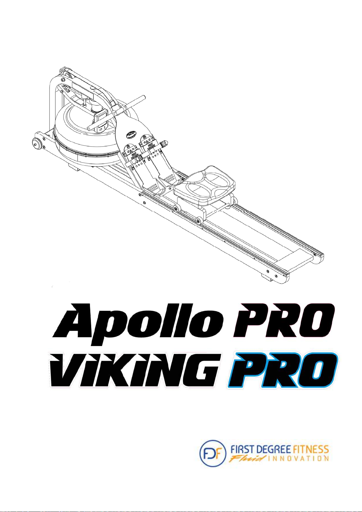
Congratulations on your purchase of First Degree Fitness Rower.
First Degree Fitness is proud to present the Apollo PRO and Viking PRO as part of
our exclusive range of commercial and home use products featuring patented Adjustable Fluid Resistance.
Apollo PRO has unique combination of precision steel and solid wood frames. Viking PRO has the combination laminate/solid wood frames. Both incorporate only
the highest quality American Ash which is collected using the latest technology in
sustainable harvesting from renewable plantations.
Note that slight variations of colour in the wooden side rails, seat and crossmember are normal and part of Mother nature’s artistry. The wood grain patterns
and subtle hues of each Rower makes every unit highly individual and designed to
compliment any environment.
Follow all instructions carefully for correct assembly, tank filling, water treatment,
service and safety.
Access to our world-wide distributor and service network is available at
www.firstdegreefitness.com
Check contents of Box 1 and Box 2 to assure all parts are present and correct prior
to assembly.
2
Page 3
Training with the Rower
1. As with any piece of fitness equipment, consult a physician before
beginning your Rower exercise program.
2. Follow instructions provided in this manual for correct foot position
and basic rowing techniques.
3. For more detailed rowing techniques, please refer to our international
website at www.firstdegreefitness.com
CAUTION
1. Keep hands and fingers away from moving parts, as indicated in this
manual.
2. The Rower can stand vertically for storage. Make sure a secure location is chosen, such as the corner of a room or against a wall on
an even, secure surface.
Note: If the storage area is not level, an additional fixture is re-
quired (sold separately) to keep the Rower stable with vertical
storage position.
3
Page 4

Contents
Rower Box Contents
Side Rail/Rear Brace/Transport Wheel Assembly
Mounting Rower Seat and Upper Mainframe
Completing The Assembly
Adjustable Resistance (AR) Tank
Note on Filling the AR Tank
Tank Filling and Water Treatment
5
7
8
10
11
12
13
Removing/Changing Tank Water
Slider Footplate
How to Row?
How Often?
Rower Computer
Using the First Degree Fitness USB Interface
Detaching the Rower Belt
14
15
16
16
17
18
19
Reattaching the Rower Belt
Maintenance Chart
Troubleshooting
Warranty
4
19
21
22
23
Page 5
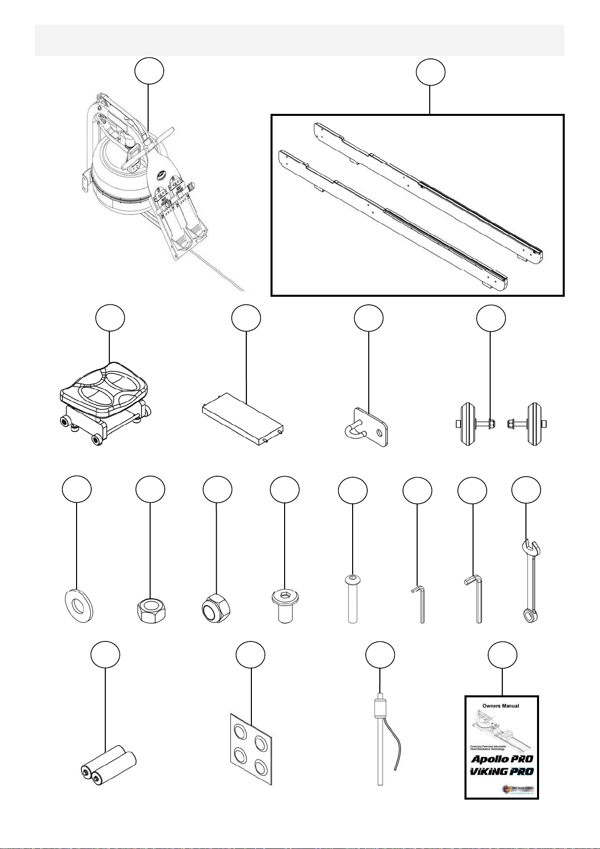
Rower Box 1 & 2 Contents
3
1
Box 1 Contents
4
5
2
Box 2 Contents
6
7
15
8
9
16
10
11
17
12
13
18
14
5
Page 6

Item Qty Description Item Qty Description
1 1 Mainframe 10 4 M6x15mm Bolt
2 2 Left / Right Side Rail 11 8 M8x45mm Bolt
3 1 Rower Seat 12 1 5mm Allen Key
4 1 Rear Brace 13 1 6mm Allen Key
5 1 Bungee Hook Mount 14 1 13mm Spanner
6 2 Transport Wheel Assembly 15 2 AA Duracell Battery
7 16 M8 Washer 16 4 Water T reatment Tablet
8 8 M8 Standard Nut 17 1 Siphon
9 8 M8 Nylock Nut 18 1 Owners Manual
6
Page 7
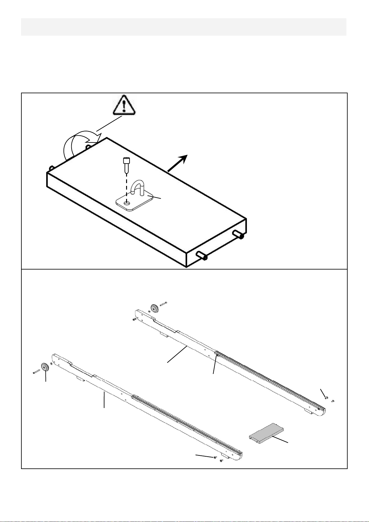
Side Rail/Rear Brace/Transport Wheel Assembly
Start with the Rear Brace and on the underside you will find a pre-installed bolt.
From the hardware kit, take the Bungee Hook Mount and install it onto the Rear
Brace as shown. Note the orientation of the Brace and Hook must be correct in
order to hold the end of the Bungee Shock Cord as depicted by the arrow in the
illustration, which points toward the front of rower.
Rotate Rear Brace to correct orientation before
assembly onto Side Rails
Towards Front of Rower
Pre-installed bolt
Bungee Hook
Mount
Rear Brace
(Underside)
Next, connect the Side Rail Left[2] and Side Rail Right[2] using 4x M6x15mm Bolts
[10] and Rear Brace[4]. Do not tighten.
Side Rail Right
Bumpstop
Transport Wheel
Assembly
Side Rail Left
Rear Brace
M6x15mm Bolts
Tip: Bumpstops facing inside of rail for correct assembly orientation.
7
M6x15mm Bolts
Page 8
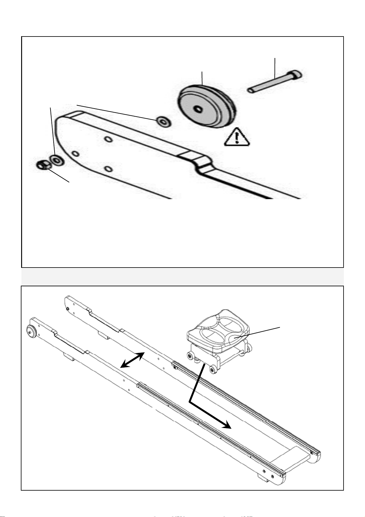
Transport Wheel Assembly
Transport Wheel
Washer
Side Rail Right
Nylock Nut
Transport Wheel Axle
Note Transport wheels
must be mounted on the
outside of Side Rails as
pictured above.
Once the Rear Brace and Side Rails are assembled, mount the Transport Wheel
Assembly onto the Left/Right Side Rails
Note: One washer on outside and one washer on the inside of the side rail.
.
Do not over tighten the Transport Wheel Axle as it may inhibit Transport Wheel rotation.
Mounting Rower Seat and Upper Mainframe
To install the rower seat, spread the
Left/Right Side Rails slightly and drop
the Rower Seat into the track.
Note Seat indentation must face
rearward.
Rower Seat
Seat Indentation
8
Page 9
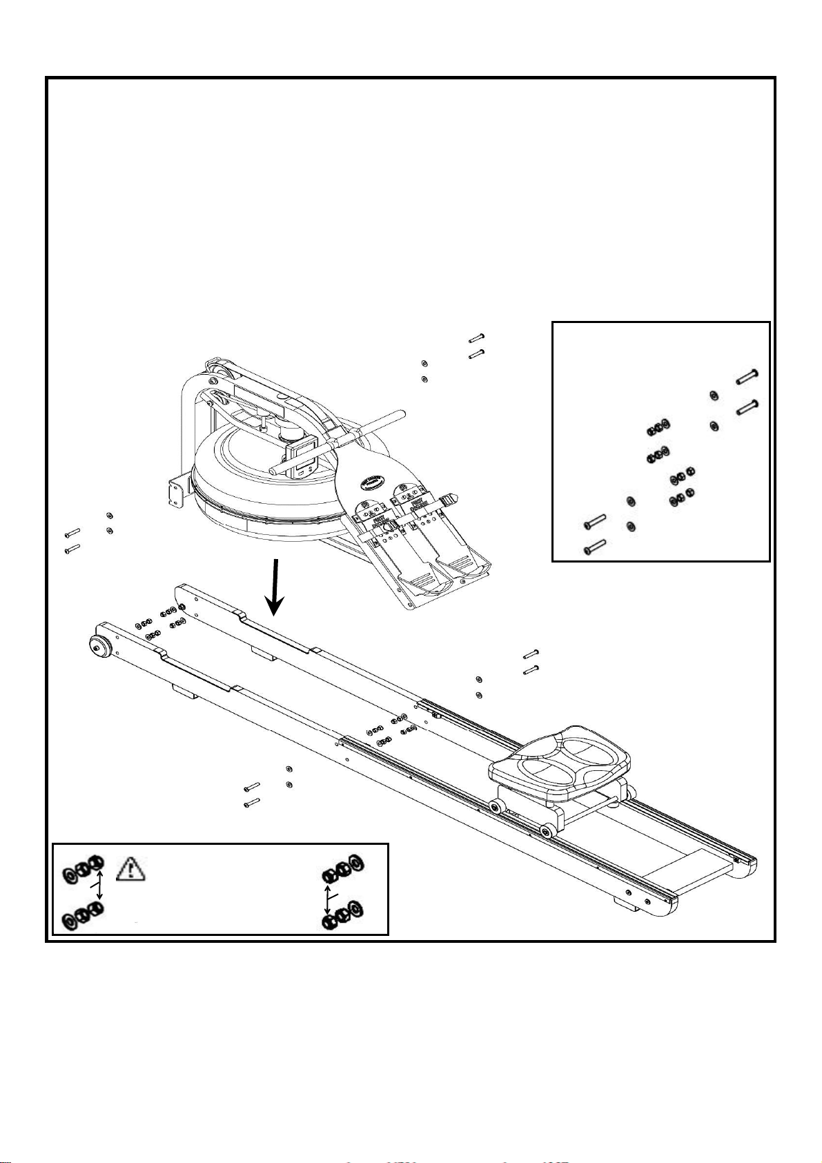
Next, install the Mainframe[1] onto the Side Rail Assembly as shown. You will need
8x M8x45mm Bolts[11], 16x M8 Washers[7], 8x M8 Standard Nuts[8] and 8x M8
Nylock Nuts[8].
Secure but do not tighten. You may find that the Lower Bracket Bolts can be difficult to access. You can tighten these bolts completely once the Rower is standing
in the vertical position so for the moment, simply align and loosely thread lower
bolts/nuts.
Bolt Assembly Close Up
M8x45mm Bolt
M8 Standard Nut
M8 Nylock
Nut
M8 Washer
M8 Washer
Nylock Nuts must be
Nylock
Nuts
outside the standard
nut and washer to properly
Nylock
Nuts
secure assembly.
Note: Clean Wheels and Runners weekly with a soft dry cloth in order to
decrease the rate of wear on both Wheels and Runners.
9
Page 10
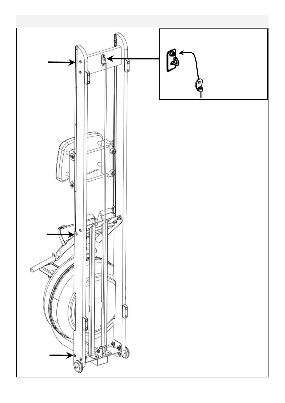
Completing The Rower Assembly
Tighten
Frame Bolts
securely once
rower is
standing.
Pull Bungee Cord and hook Bungee end
onto the Bungee Hook Mount as shown.
Once the Bungee Cord is attached to the Rear
Brace, tighten the bolts holding the Footboard,
the Mainframe to Side Rail Bolts as they are easier to access from the vertical position.
Lower the Rower back to the Horizontal position
and test for proper bungee recoil.
Check Seat Rollers/Runners for dirt or debris before sitting on the Rower Seat. Small objects captured between the Seat Rollers and Runners can
damage the Wheels or running surface. Check
Runners for debris prior to each use and clean
regularly.
Note: The Rower Frame Bolts require periodic
checking for tightness. Do this at the end of the
first month of use and again after every 12
months
Choose a suitable location when standing the
Rower for storage.
The Rower Frame can be polished with any high
grade furniture polish to further highlight the rich
luster of the wood finish.
Install supplied 2x AA Duracell battery and check
computer function. Details regarding can be
found in the Computer section of this manual.
Choose a flat, level surface on which to use your
Rower, to avoid rocking and potential premature
wear.
10
Page 11
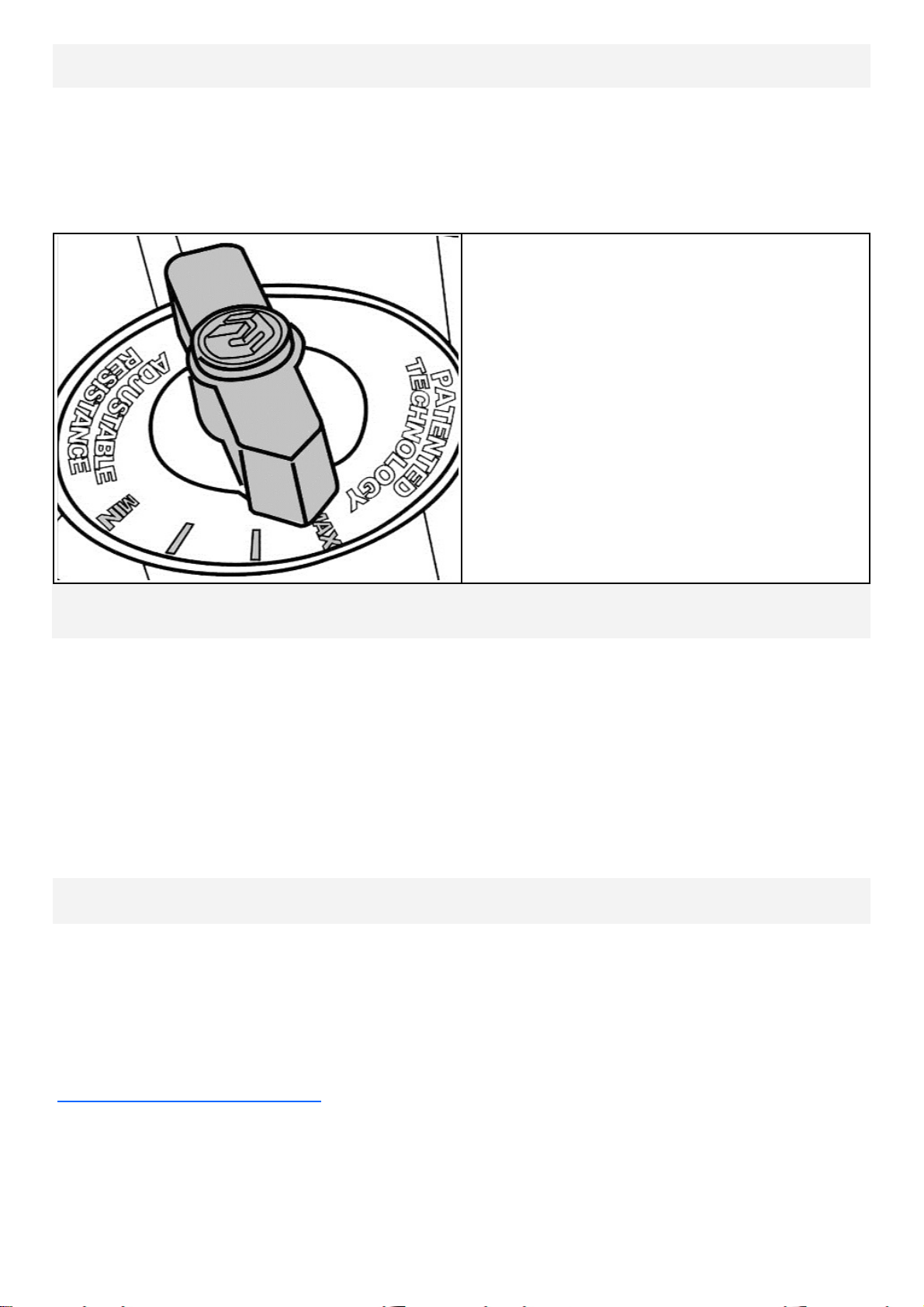
Adjustable Resistance (AR) Tank
The Adjustable Resistance (AR) Tank, developed and patented by First Degree
Fitness, offers a true multi-level experience. Water is moved between the
"storage" and "active" chambers of the AR Tank. Your new Rowing Ergometer
can adapt - at the turn of a dial - to the resistance preferred by each user in the
home environment.
MAX: This setting allows the maxi-
mum amount of water to reach
the flywheel for heaviest re-
sistance
———
———
MIN: Keeps a portion of the water in
reserve creating light resistance.
Getting Started
To achieve minimum resistance, select "MIN" on the tank adjuster. It takes 10
strokes to fill the central (storage) tank, leaving a minimal amount of water in
the outer (active) tank. This process is always required if minimum resistance
is desired. Row hard at a steady pace (20 to 25 strokes per minute [SPM]) and
put some effort into the stroke, ensuring that good form is maintained. You can
make adjustments to the resistance level while you row. Your Rowing Ergometer
will adapt almost instantly to increases in resistance but will take up to 10 strokes to
reduce the effort required, as the central (storage) tank fills up.
Developing Your Routine
Once you have found a level that gives you the exercise required, changes can be
made to SPM and to stroke intensity to further vary your energy input. Interval
training is used by most Rowers, where a period of low intensity is combined with
short intervals of high intensity. Your FDF Rowing Ergometer allows for changes
'on the fly', to achieve multi-level resistance profiles during a single workout. For
more information on exercise routines, please visit our website at
www.firstdegreefitness.com
11
Page 12
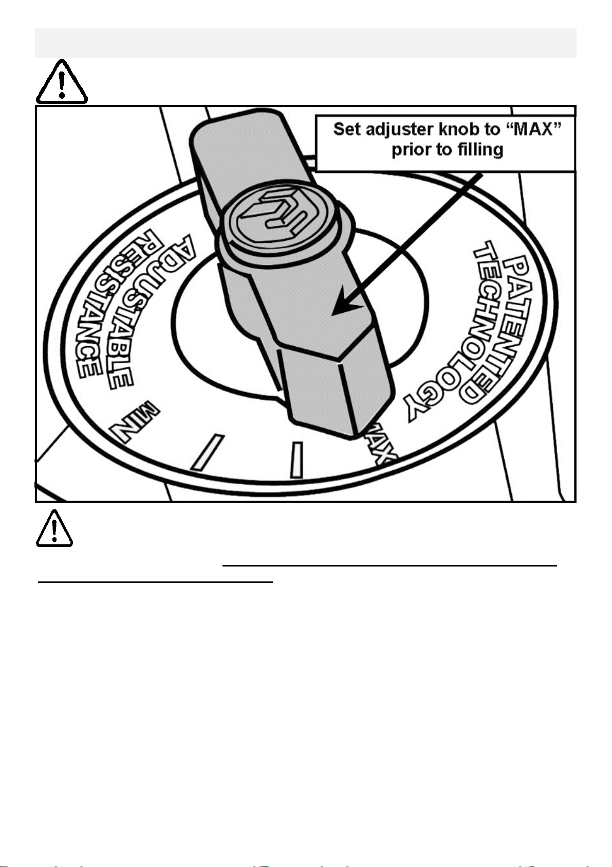
Note on Filling the AR Tank
Important: Please Read Before Filling Tank:
Caution:
When filling the AR tank, the adjuster handle must be set to the “MAX” position as
shown to allow accurate fill levels.
Using any other setting other than “MAX” will result in inaccurate fill levels and in
extreme cases could cause leakage to occur during use or when stored in the
standing position.
DO NOT overfill the tank beyond the maximum indicated level of 17 litres. Refer to
the Tank Level Decal on the lower side of the tank
12
Page 13
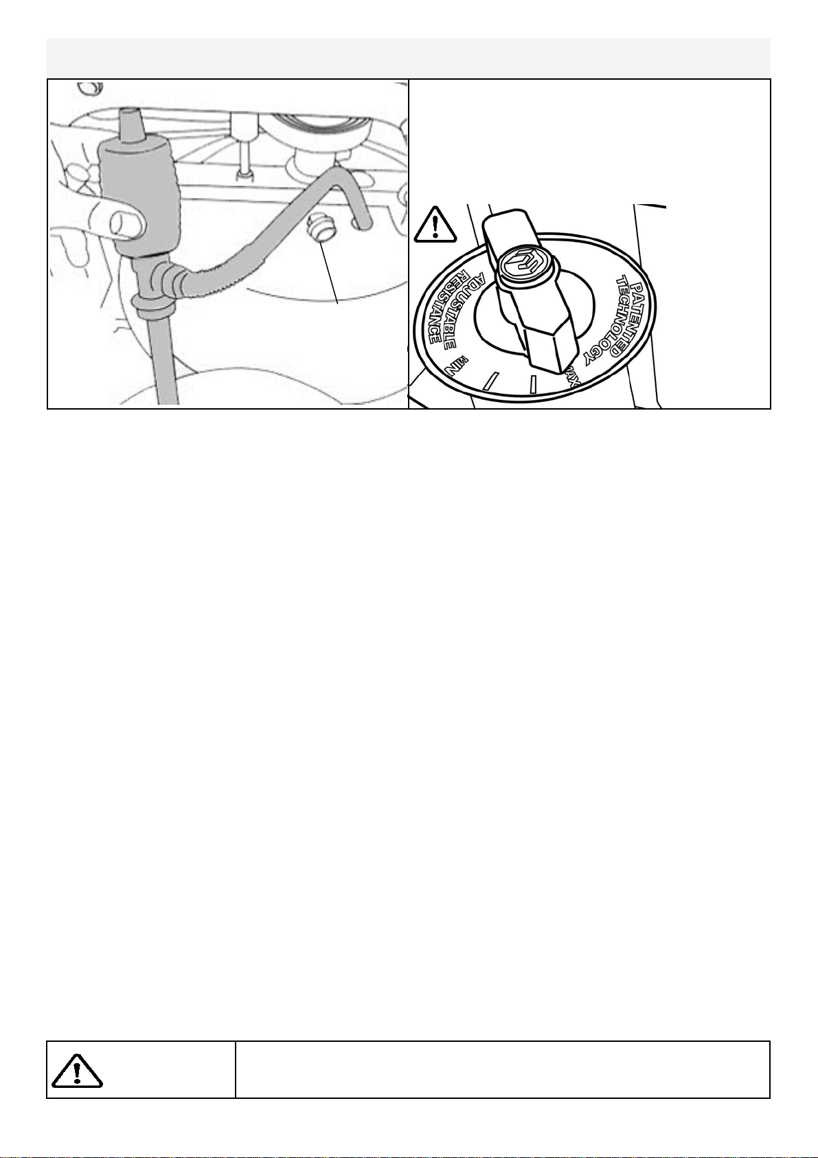
Tank Filling and Water Treatment
Tank Filling and Water Treatment Procedures
Note: 17 liters of water is required for
Siphon
maximum filling.
Fill tank
with
adjuster
handle set
Tank Plug
to “MAX”
only.
1. Remove Rubber Fill Plug from the top of the tank.
2. Place a large bucket of water next to the rower and position siphon with the rigid
hose in the bucket and the flexible hose into the tank as shown. Note: Make
sure small breather valve on the top of the siphon is closed before filling.
Note: Where water quality is known to be poor, FDF recommends the use of
distilled water.
3. Begin filling tank by squeezing siphon. Use Level Gauge Decal on side of tank to
measure volume of water in tank. Important: Do not overfill tank!
4. After filling tank to the desired water level, open the valve on the top of the
siphon to allow excess water to escape.
5. Ensure that Tank Plug is replaced once filling and water treatment procedures
are complete.
Tips on Siphon use: Putting the fill bucket higher than the tank will allow the
siphon to "self-pump" when adding water to the tank.
Water Treatment Procedures:
Add Water Treatment Tablets.
Note: The amount of water treatment can vary widely depending on the Rower’s
location and exposure to sunlight. DO NOT, UNDER AN CIRCUMSTANCES USE
ANY TREATMENT TABLETS OTHER THAN THOSE SUPPLIED WITH YOUR
ROWER. Your rower box contents include 4x Water Treatment Tablets, which is
sufficient for several years of water treatment. Treat when water becomes discolored or shows signs of Algae/Bacterial growth. To purchase additional W ater Treat-
ment Tablets, please consult your nearest regional dealer/distributor or
check our website at www.firstdegreefitness.com
Caution:
Use a drop cloth under the tank when filling the tank to avoid
staining floor or carpet.
13
Page 14
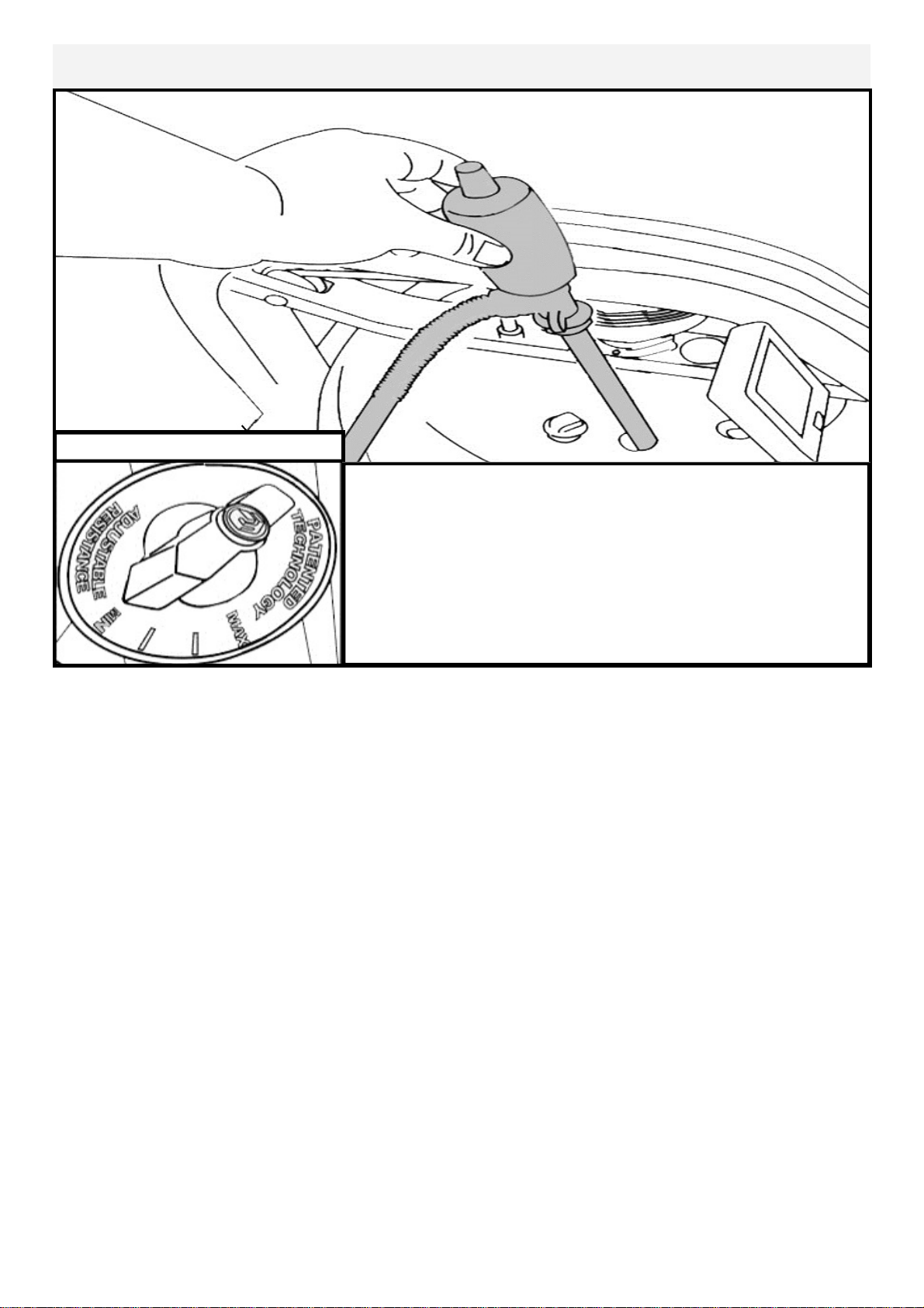
Removing/Changing Tank Water:
Set Adjuster handle to “MIN”
Row a minimum of ten complete strokes before commencing tank draining. Remove tank plug, insert rigid
end of siphon into tank and begin draining.
NOTE: Approximately 40% of tank water will remain.
It is not possible to completely drain the A/R tank
without disassembly.
1.Set Adjuster handle to “MIN”
2.Row at least ten strokes to fill the storage reservoir as completely as possible.
3.Remove Tank Plug.
4.Insert rigid end of siphon into the tank, and flexible hose into a large bucket.
5.Drain tank (approx. 40% of water will remain) and then refill following directions for
Tank filling as described in the Tank Filling section of this manual.
Note: The valve on top of the siphon must be closed to allow proper drainage.
Note: Water treatment will preclude the need to change tank water if the treat-
ment schedule is maintained. Additional chlorine is required only when discoloration appears in the water.
Note: Exposure to full sunlight reduces the life of the Water Treatment Tab-
lets. Storing the rower away from direct sunlight will extend the time between
water treatments.
14
Page 15
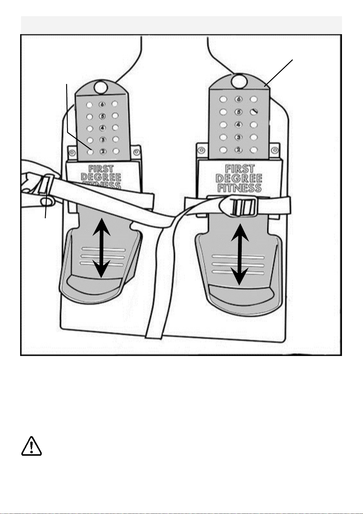
Slider Footplate
Mounting pegs
To adjust, lift and slide
Footstrap
The Slider Footplate is designed to fit a wide range of foot sizes, and is very simple to use.
To adjust, lift the top of the sliding portion of the footplate and slide up or down. The numbers 1-6
represent a guideline from which the proper length can be determined. Secure the plate onto the
mounting pegs and push down firmly to lock into position.
Tighten the Footstraps securely and begin your workout.
WARNING: Never operate this rower without feet properly secured in Footstraps, or
without the sliding portion of the Slider Footplate locked into position!
15
Page 16
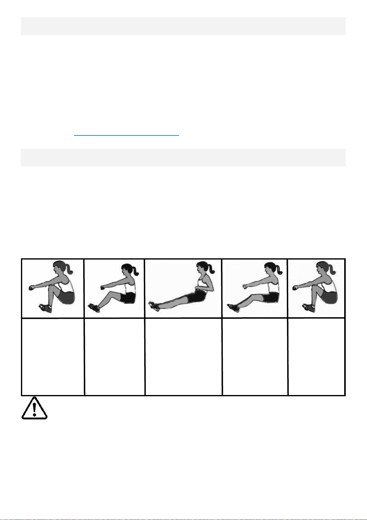
How to Row?
1. Begin the stroke comfortably forward and push strongly back with your legs while
keeping your arms and back straight.
2. Begin to pull your arms back as they pass over your knees and continue the
stroke through to completion rocking slightly back over your pelvis.
3. Return to the starting position and repeat.
4. For further details regarding rowing technique please refer to our international
website at www.firstdegreefitness.com
How Often?
Begin with 5 minute training sessions once a day and aim for around 2:30 to 2:45
for 500m time. Row at a pace that keeps the water circulating continuously between strokes.
Progress a few minutes more each day until you are comfortable with 30-45
minutes training time 3 or 4 times a week.
This will provide aerobic endurance benefits, muscle toning and sufficient calorie
burning to form part of a weight loss program.
Catch
Comfortably forward with
straight back and
arms.
Drive
Push with the
legs while arms
remain straight.
Finish
Pull through with arms
and legs rocking
slightly back on your
pelvis.
Recovery
Upper body tips
forward over your
pelvis and move
forward.
CAUTION
Always consult a doctor before beginning an exercise program.
Stop immediately if you feel faint or dizzy.
Catch
Catch and begin
again.
16
Page 17
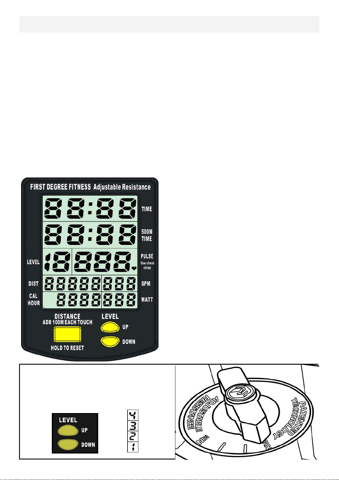
Rower Computer
Options:
Auto Start: Commence rowing to activate.
Reset all values: Hold button down for 3 seconds first to RESET.
Distance: Add 100m distance, up to 1000m then add 500m, each button push
to accumulate required distance then begin rowing to initiate distance
count down
Auto-Pause: A temporary halt in exercise will result in the following:
For over 5 seconds and under 5 minutes:
SPM/500METER/WATT to zero.
Distance/TIME values are saved.
CAL per hour defaults to Total CAL.
A Resumption in exercise in less than 5 minutes will resume Distance
TIME/ from saved values automatically.
Auto Power Down: Over 5 minutes. All values revert to zero after re start.
Computer Instructions:
TIME: Auto start elapsed time.
500M TIME: Time to row 500 m e ters,
updated at the completion of
each stroke.
PULSE: Requires optional receiver and
chest strap (sold separately).
SPM: Strokes per minute updated each
stroke.
WATT: Unit of power updated per row-
ing stroke.
CAL HOUR: Updated each stroke.
Use the LEVEL UP/ DOWN buttons in
conjunction with the Fluid Tank Resistance
Adjuster handle for accurate 500M/
Distance/CAL/WATTS.
MAX:
——
——
MIN:
17
Page 18

Using the First Degree Fitness USB Interface
Description:
The USB connectivity now built in to all new models of FDF Console and IPM allow
you to enhance your exercise experience by connecting to your home PC or Laptop.
Using FDF's own sample applications you can exercise while enjoying your favorite
movies. NetAthlon 2 XF for Rowers lets you race with other Internet connected rowers in a Virtual Reality 3D environment or train solo.
Setting up USB connectivity
1.Download and Install the USB Device Driver (CDM2xxxx_Setup.exe for 32 and
64 bit Windows 7/Vista/XP) from the FDF Website.
2.Download and Install the Sample USB Applications from the FDF Website
(www.firstdegreefitness.com).
Download and Install NetAthlon 2 XF for Rowers from
http://www.webracing.org/downloads.htm
Connecting your console
- The USB Connector is located on a flying lead at the rear of the IPM, along with
the Sensor and Heart Rate Monitor Connectors.
- Connect to a Laptop or PC using a standard USB cable, you may need to wait
while Windows starts the USB Device Driver.
Note: Please refer to computer manual where applicable or for further
information refer to our website at www.firstdegreefitness.com
18
Page 19
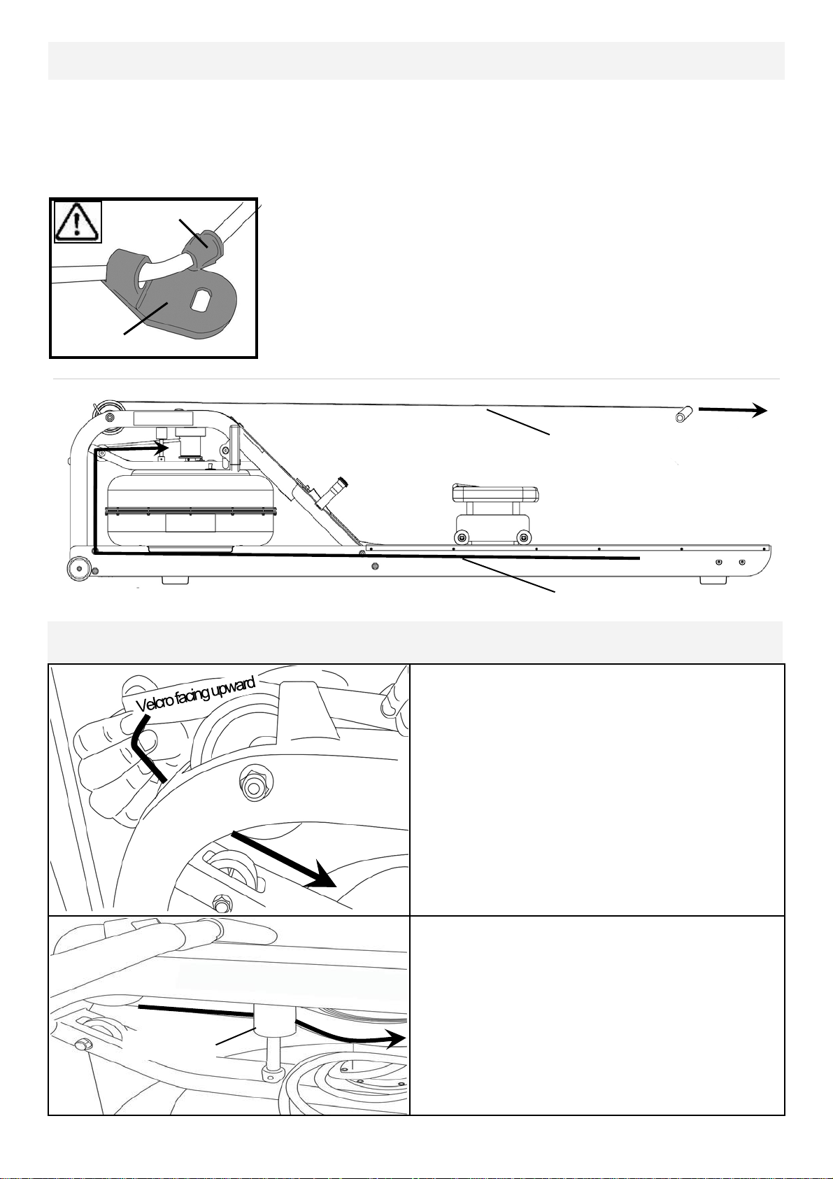
Detaching the Rower Belt
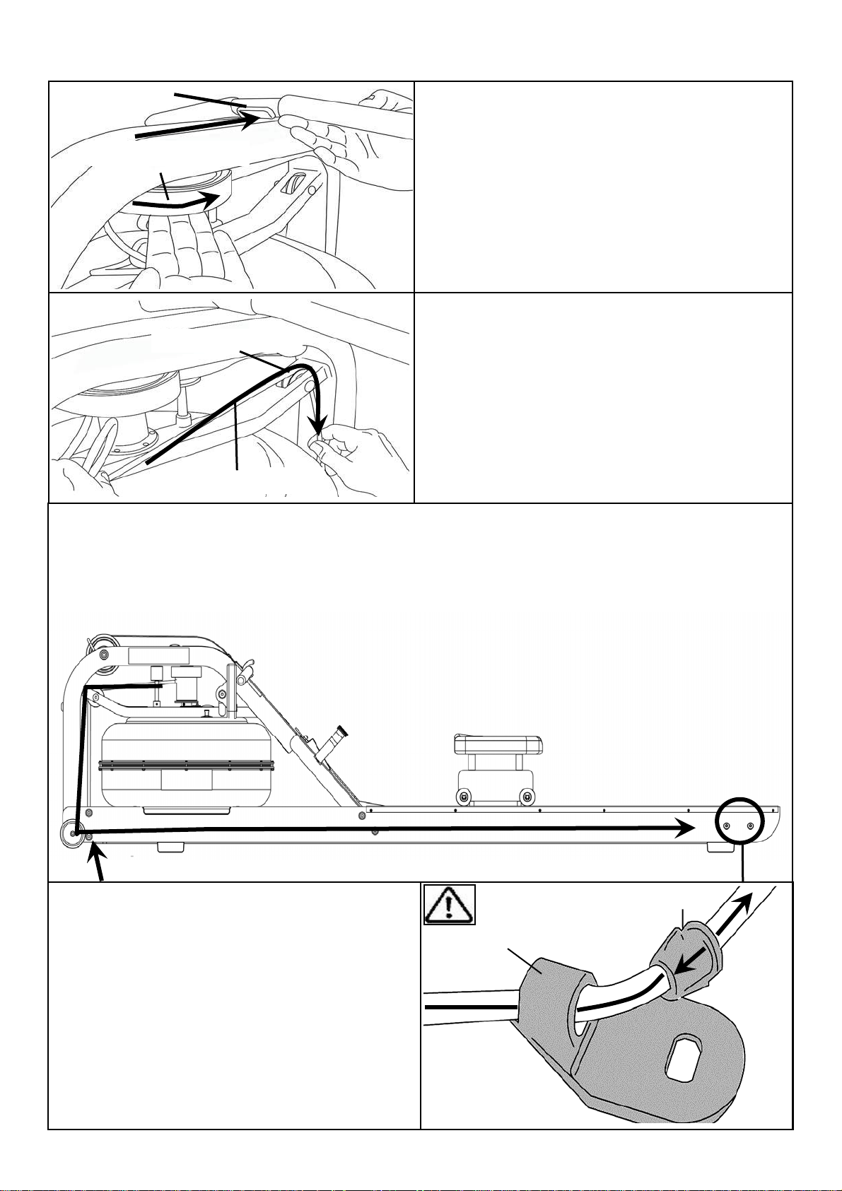
1. To detach belt, simply pull beyond the range of the normal rowing stroke until the
belt detaches from the belt bungee pulley.
Tip: You’ll hear the Velcro separating just before the belt detaches.
Bungee Hook End Frame
Inner Clip
2.Unhook the Bungee Shock Cord from the Rear Leg.
Then, push out the Inner Clip from the Bungee Hook End
Frame. Pull the Bungee through the Inner Clip until free.
This will allow for the Bungee Shock Cord to be threaded
completely out of the Main Frame and up to the Belt
Bungee Pulley where it will be re-attached once the Rower Belt is in the proper position.
1.
2.
Reattaching the Rower Belt
Idle Wheel
1.Begin reattaching the Rower Belt by
threading around the Rower Belt Pulley
with the Velcro side facing upward as
illustrated.
2.Next, thread the Belt around the Idle
Wheel as shown. Once around the Idle
Wheel, attach the Rower Belt to the
Belt/Bungee Pulley. There is an obvious “lip” at the attachment point.
19
Page 20
Rower Handle
Belt/Bungee Pulley
Bungee Pulley
Bungee Shock Cord
3.Wind the Rower Belt onto the Belt/
Bungee Pulley until the Rower Handle
is as it’s furthest forward position.
4.Rethread the Bungee Shock Cord (on
opposite side of the Idle Wheel) back
through the Bungee Pulleys and tie off
at the Attachment Point.
Recoil tension will decrease over time as the Bungee Shock Cord stretches. To increase recoil tension, simply push the Inner Clip out of the Bungee Hook End
Frame from behind, pull the required amount of bungee through the Inner Clip and
replace the Inner Clip into the Bungee Hook End Frame as shown below.
Hint: Before reattaching the Inner
Inner Clip
Clip/Bungee Hook End Frame, tie a slip
knot under slight tension at the lower
Bungee Hook End Frame
bungee pulley. This will keep the bungee
under tension while reassembling the
Bungee Hook End Frame.
20
Page 21
Maintenance Chart.
Item Timeframe Instructions Notes
Seat Wheels
and Runners
Frame Weekly Wipe down Frame with lint
Tank and Water Treatment
Weekly Wipe down Seat Wheels and
Runners with lint free cloth.
free cloth.
12 months to 2 years Follow instructions as speci-
fied in the “Water Treatment”
section of this manual.
Bungee Cord Check every hundred
hours for correct tension and for signs of
wear.
Rowing Belt Check every hundred
hours for correct tension and for signs of
wear.
The Bungee Cord should last
for many years. If a Bungee
Cord change is required,
please contact your local service representative or go
online at
www.firstdegreefitness.com
for further details.
The Rowing Belt should provide many years of trouble
free use. If a Rowing Belt
change is required, please
contact your local service
representative or go online at
www.firstdegreefitness.com
for further details.
21
Page 22

Troubleshooting:
Fault Probable Cause Solution
Water changes color
or becomes cloudy.
Rower Belt slipping
off belt/ bungee pulley.
Inconsistent readings on the Rower
Computer for
500meter split time
and SPM (strokes
per minute).
Rower is in direct
sunlight or has not
had water treatment.
Local tap water is
of poor quality.
Bungee not under
enough tension.
Recoil not strong
enough
Sensor gap
Faulty Sensor
Sensor has moved
out of position
Wiring harness
Change rower location to reduce direct exposure to sunlight. Add water
treatment or change tank water as
directed in the water treatment section of this manual. Consider using
distilled water to refill tank.
Tighten bungee cord following the
instructions in "reattaching the rower
belt" section of this manual.
Use the back cover of the computer
as a “Gap tool” to check the gap between sensor head and Magnetic
ring, or see if the Sensor head has
moved out of position.
Please contact your nearest FDF
customer service center for details
The Rower Computer does not illuminate after battery installation.
The Rower Computer screen illuminates, but does not
register when rowing.
Batteries installed
incorrectly or need
replacing.
Loose or failed connection.
Sensor gap too
wide
22
Replace/reinstall batteries in correct
position and try again. If the LCD
screen fails to illuminate, try rotating
the batteries slightly in the computer.
If this fails, contact your local service
center.
Check that the computer lead is connected properly. If it is connected
then contact your local service center. Check Sensor gap
Page 23

APOLLO PRO / VIKIVG PRO ROWER
INTERNATIONAL WARRANTY – FULL COMMERCIAL USE
First Degree Fitness Limited warrants that the Apollo PR O / V iking PR O ( mode l H YBP R O / V IKP R O ) ,
purchased from an authorised agent and in its undamaged original packaging, is free from defects in
materials and workmanship. First Degree Fitness Limited or its agent will, at their discretion, repair or
replace parts that become defective within the warranty period, subject to the specific inclusions and
exclusions below.
Metal/Wood Frame – 5 Year Limited Warranty
First Degree Fitness will repair or replace the Metal / Wooden Main Frame of the Rower should it fail
due to any defect in materials or workmanship within 5 years of the original purchase. Warranty does
not apply to frame coating.
Polycarbonate Tank & Seals – 3 Year Limited Warranty
First Degree Fitness will repair or replace the polycarbonate tank or seals should they fail due to any
defect in materials or workmanship within 3 years of the original purchase.
Mechanical Components (of a non-wearing nature) – 2 Year Limited Warranty
First Degree Fitness will repair or replace any mechanical component should it fail due to any defect
in materials or workmanship within 2 years of the original purchase.
Specific Inclusions
Seat Frames
Stainless Steel Impeller Assembly
All Other Components (of a wearing nature) – 1 Year Limited Warranty
First Degree Fitness will repair or replace any component should it fail due to any defect in materials
or workmanship within 1 year of the original purchase.
Specific Inclusions
Bungee Recoil Cord
Hand Grips & Foot Straps
Rowing Belt
Seat and Seat Runners
All pulleys, rollers & bearings
All rubber components
Computer & speed sensor (excluding replaceable batteries)
Footplates (pivoting & sliding)
General Exclusions
Damage to the finish of any part of the machine
Damage due to neglect, abuse, incorrect assembly or use of the machine
Any charges for freight or customs clearance associated with the return or dispatch of parts
Any damage to or loss of goods during transport of any kind
Any labour cost associated with a warranty claim
General Conditions
The serial number of the machine must be correctly registered with First Degree Fitness Limited
or one of its appointed distributors
First Degree Fitness Limited reserve the right to examine any part where replacement is claimed
under warranty
Warranty period applies only to the original purchaser from the date of purchase and is not
transferable
The product must be returned to your place of purchase in original packaging with transportation,
insurance and associated charges paid for by you and risk of loss or damage assumed by you
First Degree Fitness makes no other warranties except as stated here and expressly disclaims
all warranties not stated in this warranty. Neither First Degree Fitness nor its associates shall be
responsible for incidental or consequential damages
Manufacturer's warranty automatically commences upon sale of the product to end user or upon
the expiration of one (1) year from month of manufacture, whichever occurs first
23
 Loading...