

Page 1
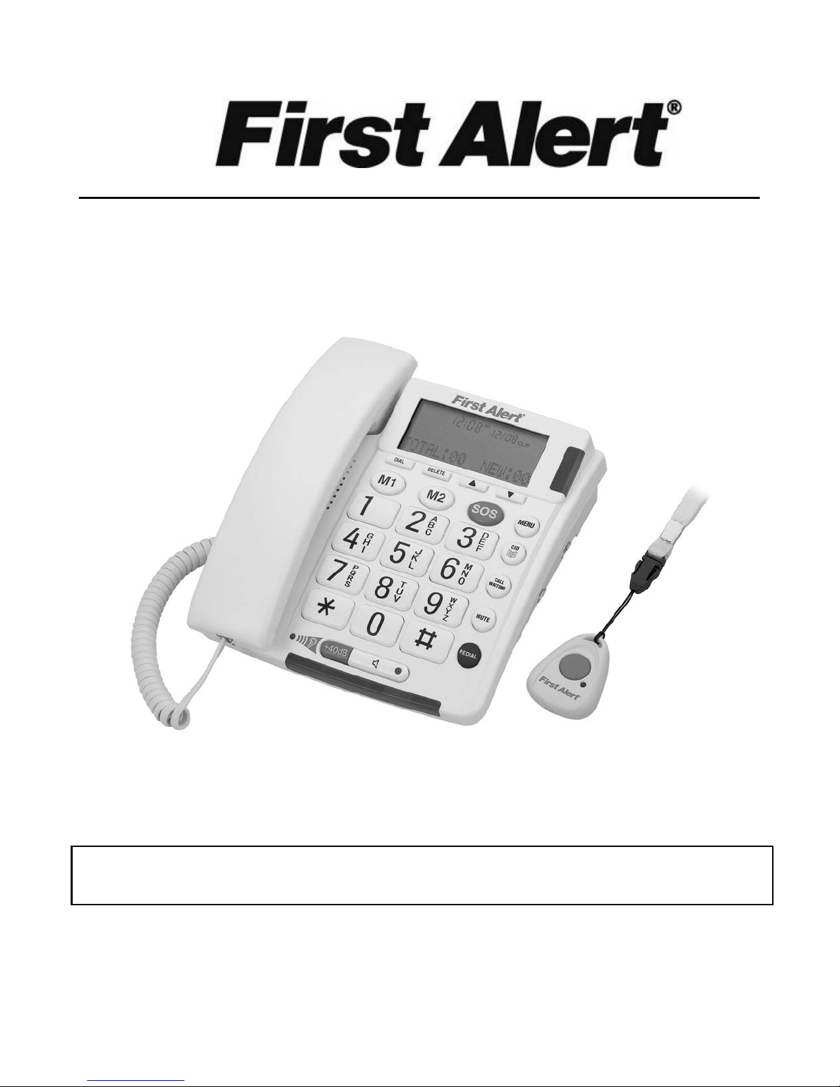
BIG BUTTON TELEPHONE WITH EMERGENCY KEY
AND REMOTE PENDANT
USER MANUAL
SFA3800
SUBSCRIPTION TO CALLER ID SERVICE F ROM YOUR LOCAL TELEPHONE COMPANY
IS REQUIRED FOR ALL CALLER ID FEATURES TO OPERATE CORRECTLY
PLEASE READ THIS USER MANUAL COMPLETELY BEFO RE OPERATING THIS UNIT AND
RETAIN IT FOR FUTURE REFERENCE
Page 2
IMPORTANT SAFETY INSTRUCTIONS
THIS SYMBOL IS TO ALERT YOU THE IMPORTANT
OPERATING OR SERVICING INSTRUCTIONS THAT MAY
APPEAR IN YOUR USER MANUAL. ALWAYS FOLLOW BASIC
SAFETY PRECAUTIONS WHEN USING THIS PRODUCT TO
When us ing your telephone equipment, basic safety precautions should always be followed to reduce
the risk of fire, electric shock and injury to persons, including the following:
1. Read and understand all instructions.
2. Follow all warnings and instructions marked on the product.
3. Unplug this product from the telephone line and ac adaptor before cleaning. Do not use liquid or
aerosol cleaners. Use a damp cloth for cleaning.
4. Do not use this product near water, for example, near a bath tub, wash bowl, kitchen sink, or
laundry tub, in a wet basement, or near a swimming pool.
5. Do not place this product on an unstable cart, stand, or table. The product may fall, causing serious
damage to the product.
6. Slots and openings in the enclosure and the back or bottom are provided for ventilation to prevent
overheating. These openings must not be blocked or covered. The openings should never be
blocked by placing the product on a bed, sofa, rug, or other similar surface. This product should
never be placed near or over a radiator or heat register. This product should not be placed in a
built-in installation unless proper ventilation is provided.
7. This product should be operated only from the type of power source indicated on the marking label.
If you are not sure of the type of power supply to your home, consult your dealer.
8. Do not allow anything to rest on the power cord of the ac adaptor. Do not locate this product where
the cord will be abused by persons walking on it.
9. Always plug the ac adaptor into an outlet that is easily accessible and near to the equipment.
10. Never push objects of any kind into this product through enclosure slots as they may touch voltage
points or short out parts that could result in a risk of fire or electric shock. Never spill liquid of any
kind on the product.
11. Do not disassemble this product. Take it to a qualified service technician or service center when
repair work is required. Opening or removing covers may expose you to voltage or other risks.
Incorrect reassembly can cause electric shock when the appliance is subsequently used.
12. Unplug this product from the wall outlet and refer to qualified service personnel under the following
conditions:
a) When the power supply cord or plug is damaged or frayed.
b) If liquid has been spilled into the product.
c) If the product has been exposed to rain or water.
d) If the product does not operate normally by following the operating instructions. Adjust only
those controls that are covered by the operating instructions. Improper adjustment of other
controls may result in damage and may require extensive work by a qualified technician to
restore the product to normal operation.
e) If the product has been dropped or the enclosure has been damaged.
f) If the product exhibits a distinct change in performance.
13. Avoid using a telephone during a lightning storm. There may be a remote risk of electric shock from
lightning.
14. Do not use the telephone to report a gas leak in the vicinity of a leak.
15. Never install telephone wiring during a lightning storm.
REDUCE THE RISK OF INJURY, FIRE OR ELECTRIC SHOCK.
E-1
Page 3

16. Never install telephone jacks in wet locations unless the jack is specifically designed for wet
locations.
17. Never touch uninsulated telephone wires or terminals unless the telephone line has been
disconnected at the network interface.
18. Use caution when installing or modifying telephone lines.
For optimal performance it is recommended that this product is used on a conventional phone line.
Performance may vary with VOIP or other digital services.
SAVE THESE INSTRUCTIONS
FCC INFORMATION
This equipment complies with Part 68 of the FCC Rules. The label affixed to this equipment contains,
among other information, the FCC Registration Number and Ringer Equivalence Number (REN) for this
equipment. We suggest that you review the following information provided by the FCC.
NOTIFICATION TO THE TELEPHONE COMPANY
Notification to the telephone company is no longer required prior connecting the registered equipment.
However, upon request from the telephone company the user shall tell the telephone company which
line the equipment is connected to as well as the registration number and the ringer equivalence of the
registered protective circuitry. In most, but not all areas, the sum of all REN’s should be 5.0 or less.
MALFUNCTION OF THE EQUIPMENT
If the device is not operating properly, t he user should immediately disconnect it from the telephone line
as it may cause harm to the telephone network. In t he event service is needed the user should contact:
Service Department
Spectra Merchandising International, Inc.
4230 North Normandy Avenue
Chicago, IL 60634, USA.
Telephone: (773) 202-8408 or toll-free hotline 1-800-777-5331
TELEPHONE CONNECTION REQUI REMENTS
Except for ringers provided by telephone company, all connections to the telephone network except for
made through standard plugs telephone company provided jacks, or equivalent, in such a manner as to
allow for easy and immediate disconnection of the terminal equipment. Standard jacks should be so
arranged that, if the connected plug is withdrawn, no interference to the operation of the equipment at
the customer’s premises which remains connected to the telephone network shall occur by reason of
such withdrawal.
INCIDENCE OF HARM
Should terminal equipment or protective circuitry cause harm to the telephone network, the telephone
company shall, where practical, notify the c ustomer that temporary discontinuance of service may be
required. However, where prior notices are not practical, the telephone company may temporarily
discontinue service if such action is deemed reasonable in the circumstances. In the case of such
temporary discontinuance, the telephone company shall promptly notify the customer who has the right
to bring a complaint to the FCC if he feels the disconnection is not warranted.
E-2
Page 4

CHANGES IN TELEPHONE COMPANY EQUIPMENT OR FACILITIES
The telephone company may make changes in its communications facilities, equipment, operations or
procedures, where such action is reasonably required and proper in its business. Should any such
changes render the customer’s terminal equipment incompatible with the telephone company facilities,
the customer shall be given adequate notice to make modifications to maintain uninterrupted service.
General
The FCC prohibits customer-provided terminal equipment to be connected to party lines or to be used
in conjunction with a coin telephone service.
Installation
This device is equipped with a USOC RJ11C standard miniature modular jack and is designed to plug
directly into a modular jack.
***THIS TELEPHONE HAS BEEN CERTIFIED AS HEARING AID COMPATIBLE ***
This device complies with Part 15 of the FCC Rules. Operation is subject to the following two
conditions:
(1) this device may not cause harmful interference, and
(2) this device must accept any interference received, including interference that may cause undesired
operation.
Note: This equipment has been tested and found to comply with the limits for a Class B digital device,
pursuant to Part 15 of the FCC Rules. These limits are designed to provide reasonable protection
against harmful interference in a residential installation. This equipment generates, uses and can
radiate radio frequency energy and, if not installed and used in accordance with the instructions, may
cause harmful interference to radio communications. However, there is no guarantee that interference
will not occur in a particular installation. If this equipment does cause harmful interference to radio or
television reception, which can be determined by turning the equipment off and on, the user is
encouraged to try to correct the interference by one or more of the following measures:
- Reorient or relocate the receiving antenna.
- Increase the separation between the equipment and receiver.
- Connect the equipment into an outlet on a circuit different from that to which the receiver is
connected.
- Consult the dealer or an experienced radio/TV technician for help.
CAUTION: Changes or modifications to this equipment not expressly approved by the party
responsible for compliance could void the user’s authority to operate the equipment.
DEAR FIRST ALERT® CUSTOMER
We have taken great care to make sure that your product was in perfect working order when it left our
factory. It has been designed to give you many years of enjoyment and trouble free operation. Read
this manual before operating this unit to become familiar with its features and obtain the performance
that will bring you continued satisfaction for many years.
For future reference, record the serial number in the space provided.
Model Number: SFA3800 Serial Number: ____________________
E-3
Page 5

CONTENTS OF YOUR PRODUCT
SFA3800 Telephone Set x 1 set
Coiled Handset Cord (9 feet) x 1 pc
Long Line Cord (7 feet) x 1 pc
Short Line Cord (7 inches) x 1 pc
Emergency Remote Pendant with Detachable Neck Strap (with 12V batt er y installed) x 1 set
AC Adaptor (DC9V
Wall Mount Bracket x 1 set
Wall Mounting Screws x 2 pcs
Plastic Anchors for Wall Mounting x 2 pcs
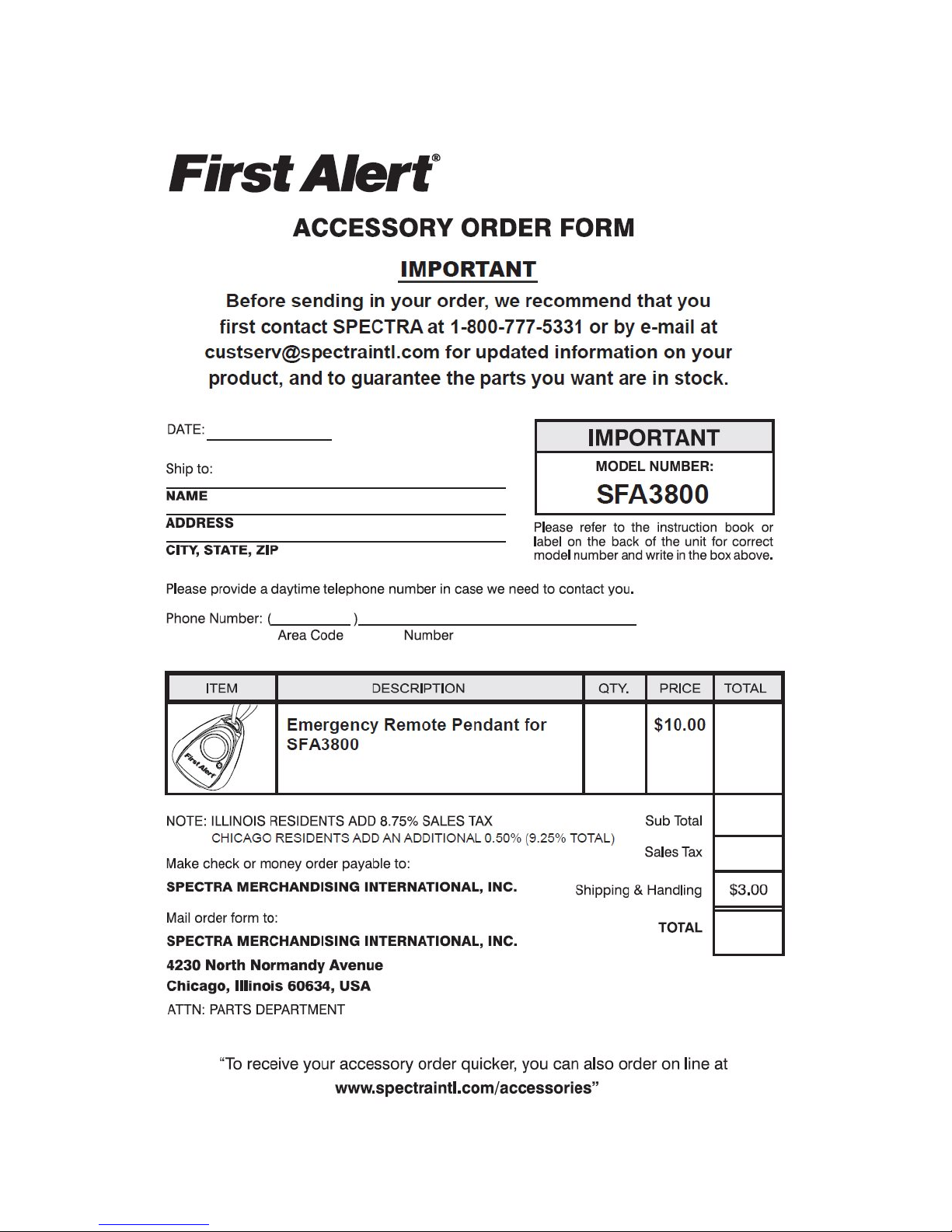
User Manual with Accessory Order Form x 1 set
200mA output) x 1 set
PROTECT YOUR FURNITURE!!
This system is equipped with non-skid rubber ‘feet’ to prevent the product from moving when you operate the
controls. These ‘feet’ are made from non-migrating rubber material specially formulated to avoid leaving any
marks or stains on your f urniture. However certain types of oil based furniture polishes, wood preservatives, or
cleaning sprays ma y cause the rubber ‘feet’ to soften, and lea ve marks or a rubber residue on t he furniture. To
prevent any damage to your furniture we strongly recomm end that you purchase small self-adhes ive felt pads,
available at hardw are stores and home im provement center s ever ywhere, and a pply these pads to the bot tom of
the rubber ‘feet’ before you place the product on fine wooden furnitur e.
E-4
Page 6
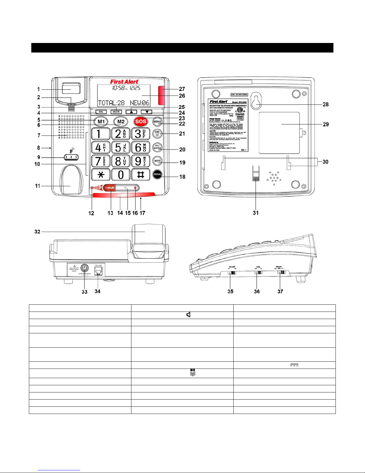
THE MAIN UNIT
1. Hook Switch
14. Ringer Indicator
27. New Call Indicator
2. Handset Holder
15. Speakerphone Button
28. Keyhole for Wall Mounting
3. Delete Butt on
16. Speakerphone Indicator
29. Battery Compartment Cover
4. Dial Button
17. Speakerphone Microphone
30. Wall Mount Bracket Slots
5. M1 Button (One-Touch Memory
Location 1)
18. Redial/Pause Button
31. Wall Mount Bracket Latch
6. M2 Button (One-Touch Memory
Location 2)
19. Mute But ton
32. Handset
7. Speaker
20. Call Waiting Button
33. DC Jack (DC9V 200mA)
8. Handset Jack
21. CID/Phonebook Button
34. Telephone Line Jack
9. Handset Volume Control
22. Menu Button
35. Slide Volume Control
10. Keypad
23. SOS But t on
36. Tone Hi/Lo Slide Control
11. Handset Cradle
24. Down Button
37. Ringer Selector (Hi/Mid/Lo)
12. Volume Boost Indicator
25. Up Button
13. +40dB Volume Boost Button
26. LCD Display
LOCATIONS OF CONTROLS
E-5
Page 7
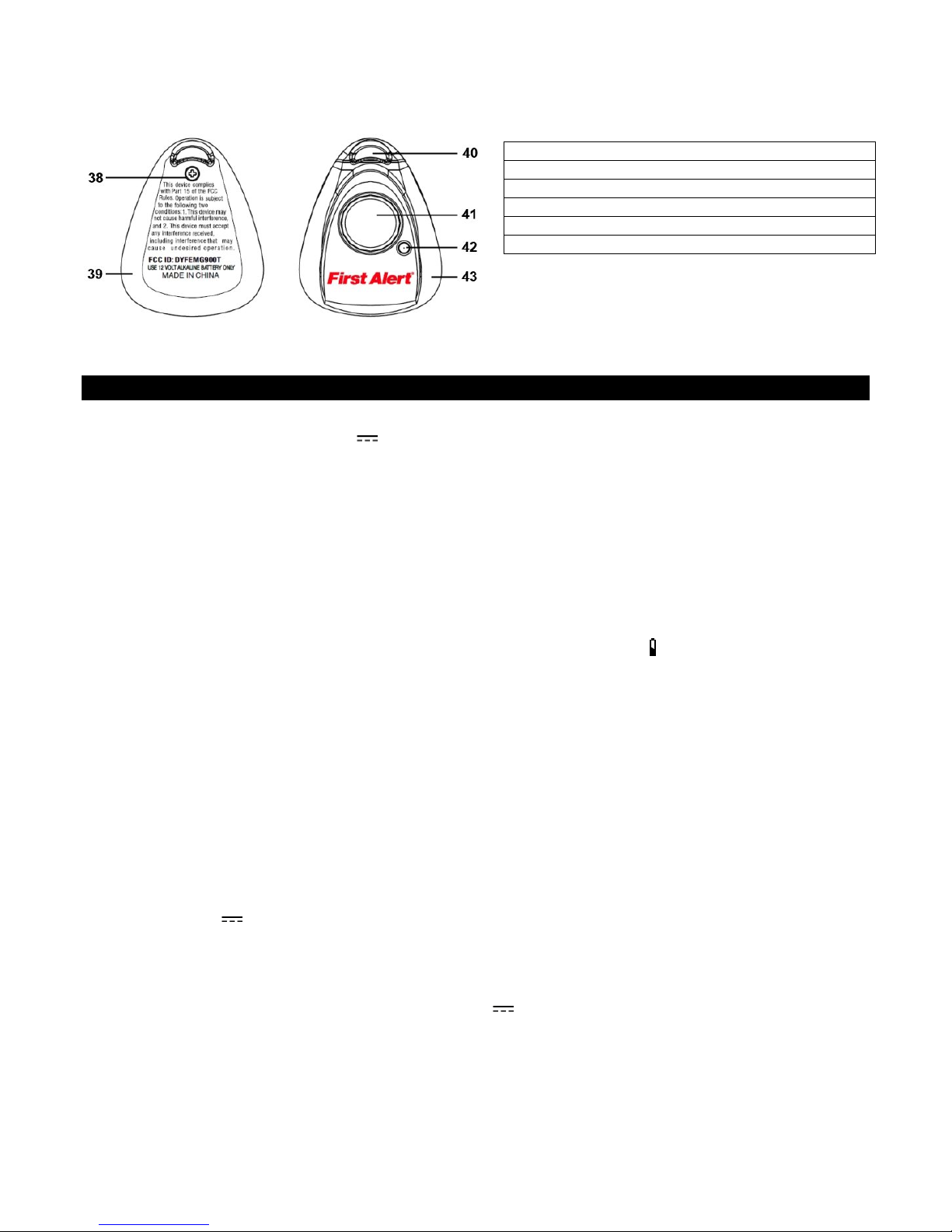
THE EMERGENCY REMOTE PENDANT
38. Remote Pendant Bottom Cover Screw
39. Remote Pendant Bottom Cover
40. Hole for Detachable Neck Strap
41. Remote Pendant Transmit Button
42. Remote Pendant Transmit Indicator
43. Remote Pendant Top Cover
INSTALLATION
POWERING UP THE TELEPHONE
Insert the plug of the AC120V~ DC9V
telephone and plug the AC Adaptor into a properly installed AC 120V~ 60H z mains socket near the equipment
and it should be easily accessible.
CONNECTING THE TELE PHONE
1. Plug one end of the telephone line cord into the TEL.LINE JACK at the bottom of the telephone base.
2. Plug the other end of the telephone line cord into the wall outlet.
3. Plug one end of the coiled cord into the handset's modular jack.
4. Plug the other end of the coiled cord into the left side of the telephone.
INSTALLING BACKUP BATTERIES
Your telephone requires f our AA batteries (not included) for back up. W hen the “
or the display gets dim, replace all the batteries with four fresh “AA” size (UM-3) ones.
Notes:
The telephone num bers in memory and the voice rec ordings are stored in no n-volatile flash m emory which
does not require battery power for backup.
When there is an AC power outage, the installed backup batt eries will au tomaticall y switch in to maintain all
normal functions of the telephone. To avoid excessive battery drain, please make sure to connect the
provided AC Adaptor properly to the telephone and household AC power all the time.
Before opening BATTERY COMPARTMENT COVER, make sure the telephone is disconnected from the
telephone line and AC Adaptor.
INSTALLING BATTERIES INTO THE TELEPHONE
1. Open the BATTERY COMPARTMENT COVER located on bottom of cabinet using a small flat-blade
screwdriver (not included).
2. Ins ert four 1.5V
the polarity markings as indicated in the compartment.
3. Snap the BATTERY COMPARTMENT COVER back into place.
CHANGING THE BATTERY IN THE EMERGENCY REMOTE PENDANT
The EMERGENCY REMOTE PENDANT comes with a 12V
You should check the batt e r y status per iod ical l y b y pre s sing the red REMOT E PENDANT TRANSMIT BUTTON. If
the red REMOTE PENDANT TRANSMIT INDICATOR gets dim and/or the tran smission distance (up to 100 feet)
becomes considerably shorter, it is time to replace the exhausted battery.
1. Remove the REMOTE PENDANT BOTTOM COVER SCREW (#38) from the back of the REMOTE
PENDANT.
“AA” size (U M-3) alkaline batteries (n ot included) into the Batt ery Compartm ent following
200mA AC Adaptor (include d) into the DC JACK at the back of the
” icon appears on the d isplay
type LR23 alkaline battery pre-installed.
E-6
Page 8

2. Insert a small flat-head screwdriver into t he rectangul ar slot at the bottom of the PENDANT to twist o pen the
DIRECT
NUMBER
N/A
LCD Contrast
Adjusts the contrast level of the LCD panel for easy reading
1
Enter Time/Date
Enter the time and date information
Language
Select the desired display language from 11 options: English
Spanish, French, Italian, German, Dutch, Turkish,
Slovenski, Portuguese, Swedish , Danish
Voice
Select the desired voice prompt language from 4 options: English
(default), Spanish, Italian, French
REMOTE PENDANT TOP COVER.
3. Remove the old battery and load a new 12V
following the polarit y markings as indicated on the PCB. (Remarks: the m etal plate with a spring is the
negative battery terminal).
4. Snap the REMOTE PENDANT TOP COVER back into place and tighten the screw on the bottom cover.
BATTERY CARE
Be sure that the batteries are installed correctly . Wrong polarity may damage the unit.
Do not mix old and new batteries.
Do not mix alkaline, standard (carbon-zinc) or rechargeable (nickel-cadmium) batteries.
If the unit is not to be used for an extended period of time, remove the batteries. Old or leaking batteries can
cause damage to the unit and may void the warranty.
Do not try to rec harge batt eries n ot inten ded to b e recharged; the y can overh eat and r upture (Follow ba ttery
manufacturer’s directions).
Do not dispose of batteries in fire, batteries may explode or leak.
MOUNTING THE PHO NE ON A WALL
The phone may be mounted on a suitable wall or other vertical surface by following the procedures below.
Select an area of the wall where you would like to hang your phone and m ake sure that there are no p ipes or
electrical cables buried in the wall in this area.
type LR23 alkaline battery into the battery compartment
Caution: Cables to electrical switches and sockets usually run vertically in the wall. Do not mount your phone
directly above or belo w an electric switch or soc ket unless you are sure th at the cables will not be dam aged by
the fixing screws.
1. Drill two holes vert icall y, one above the other, 3-1/4” (83mm) apart, and leave the scr ews protru ding f rom the
wall by about 3/16” (5mm).
Note: Adjust the amount th at the screw heads protr ude f r om the wall so that when t he p hone is f ina ll y hung,
it lies flat.
2. Press and lift out the HAND SET HO LDER. R emove the hanging peg (loca ted b y the ho ok switch) by pushing
it upwards and snap it into place so it will hold the handset in place when the phone is mounted on the wall.
3. Insert the two tabs of the WALL MOUNT BRACKET into the matching s lots opposite the keyhole slot on the
underside phone b ase. T hen pr ess dow n and slide the brack et up ward until the ta bs snap into plac e and the
bracket is latched in place by the WALL MOUNT BRACKET LATCH.
4. Plug one end of the TELEPHONE LINE CORD into the TEL. LINE JACK at the back of the base.
5. Plug the other end of the LINE CORD into t he wall plate jac k, then align the base's KEYHOLE SLOTS with
the screws and slide the telephone unit downward to secure it.
SETUP MENU
There are 11 different functions in the setup menu for this telephone.
You can press the MENU BUTTO N repeatedly to access eac h of them one by one or direct access your desired
function by pressing MENU BUTTON followed by a NUMBER of the KEYPAD as follows:
ACCESS
2
3
SETUP FUNCTION FUNCTION DESCRIPTIONS
(default),
E-7
Page 9

4
Store Number
Store a telephone number to the phone book
5
Name Recording
Record a name for a telephone number in the phone book
6
Record Message
Record a new emergenc y mess age
7
Check Message
Listen to the recorded emergency message
8
Flash
Set the flash time.
Options are: 600, 300 (default), 270, 100 and 80ms
9
Tone/Pulse
Set the dialing mode between tone or pulse.
Remote Pendant
For pairing the r emote pen dant with your telephon e (up to 5 remote
pendants can be paired)
0
SETTING THE CONTRAST OF THE LCD DISPLAY
1. Press the MENU BUTTON. The display shows “LCD CONTRAST”.
2. Press the DIAL BUTTON. The display shows the current contrast setting with values between 1 and 5.
3. Press or to select the desired contrast level and confirm with the DIAL BUTTON.
4. The display now s hows to “ENTER T IME/DATE”, you can refer to next section to set th e time and date or
press
SETTING THE TIME AND DATE
1. Press MENU BUTTON repeatedly (or press MENU then
2. Press the DIAL BUTTON. The display shows “ENTER TIME” and the hour digits are flashing.
3. Select the correct hour usi ng the or and confirm with the DIAL BUTTON. The minute digits will n ow
flash in the display.
4. Select the required m inutes using the or and confirm with the DIAL BUTTON. The display now sho ws
“ENTER DATE” and the “month” digits are flashing.
5. Select the correct m onth using the or and confirm with the DIAL BUTTON. The “date” digits will now
flash in the display.
6. Select the correct date using the or and confirm with DIAL BUTTON.
7. Press
SETTING THE DISPLAY LANGUAGE
1. Press MENU BUTTON repeatedly (or press MENU then
2. Press the DIAL BUTTON.
3. Select the desired display language from 11 options English, Spanish, French, Italian, German, Dutch,
Turkish, Slovenski, Portuguese, Swedish and Danish using the or and confirm with the DIAL BUTTON.
4. Press
SETTING THE VOICE PROMPT LANGUAGE
The telephone is factory preset with all voice features ON.
The volume of the voice prompt is regulated by the SLIDE VOLUME CONTROL.
If the user does not wish to hear the voice prompts, it can turn off the voice feature.
1. Press MENU BUTTON repeatedly (or press MENU then
2. Press the DIAL BUTTON.
3. Using the or to select between VOICE OF F or ON and the desire d languag e (Englis h, Spanish, Italian,
French) and confirm with DIAL button.
4. Press
Note: T he default setting for voice pr ompt is English, if you select other la nguages, the phon e will announce the
phone number, digits and phone Caller ID only.
SETTING THE FLASH TIME
1. Press MENU BUTTON repeatedly (or press MENU then
2. Press the DIAL BUTTON.
3. Select the desired flash ti me from 600, 300 (default), 270, 100 or 80ms using the or and conf irm by
button to exit the setup mode.
buttons) until “ENTER TIME/DATE” is shown.
BUTTON to exit the setup mode.
buttons) until “LANGUAGE” is shown.
BUTTON to exit the setup mode.
buttons) until “VOICE” is shown.
BUTTON to exit the setup mode.
buttons) until “FLASH” is shown.
E-8
Page 10

pressing the DIAL BUTTON.
4. Press
SETTING THE TONE/PULSE DIALING MODE
1. Press MENU BUTTON repeatedly (or press MENU then
2. Press the DIAL BUTTON.
3. Select the required dialing mode using the or and confirm with the DIAL BUTTON.
4. Press
SETTING THE RINGER VOLUME CONTROL
The ringer sound level can be adjusted by sliding the RINGER SELECTOR to select Hi, Mid or Lo level.
The RINGER INDICATOR will flash with all incoming calls.
ADJUSTING THE HANDSET V OLUME CONTROL
This feature is usef ul for people with im paired hearing who require extra level of amplification and tone control
offered by this telephone.
The VOLUME BOOST INDICATOR is used to indicate when the volume level is increased.
1. Press the +40dB VOLUME BOOST BUTTON, the VOLUME BOOST INDICATOR will turn ON.
2. Adjust the handset volume by turning the rotary HANDSET VOLUME CONTROL to select the desired
listening level (level 1 to 9).
3. During the convers ati on, yo u may turn OFF the volume boost b y pr ess in g t he RE D +40dB VOLUME BO OST
BUTTON again, and the VOLUME BOOST INDICATOR will turn OFF. The sound level will return to normal.
4. When you hang up, the phone will reset to normal sound level.
SETTING THE TONE CONTROL (TONE HI/LO)
The TONE HI/LO SLIDE CONTROL allows you to f it your s pec if ic h ear i ng nee ds , so words are clearer an d e as ier
to understand. Slid e the TONE HI/LO CONTROL to “Lo” to enhance the lower frequenc y range and to “ Hi” to
enhance the high frequency range.
Note: The tone control function will not be effec tive when the VOLUME BOOST INDICATOR is OFF.
SETTING THE SPEAKER VOLUME CONTROL
You can adjust the speakerphone volume to a more comfortable listening level using the SLIDE VOLUME
CONTROL.
PAIRING THE REMOTE PENDA NT
The phone comes with one remote pendant for em ergency use. You can p air up to a total of 5 pendant s to your
phone. FULL will show on the display if you attempt to pair a sixth pendant. To pair the pendant to your phone:
1. Press MENU BUTTON repeatedly (or press MENU then
2. Press DIAL BUTTON to pair your new pendant to your phone, “PAIRING” will appear.
3. Press DIAL BUTTO N again and when “PAIRING…” ap pear s, pres s the red REMOTE PEND ANT TRANSMIT
BUTTON. If the pendant is successfully paired, “PAIRED” appears, if not “PAIRING FAILURE” would appear.
4. If you want to cancel a paired pendant, select “DELETE?” and press DIAL BUTTON to confirm. A voice
prompt will confirm the successful delete action. It will then exit to normal display automatically.
BUTTON to exit the setup mode.
buttons) until “TONE/PULSE” is shown.
BUTTON to exit the setup mode.
buttons) until “REMOTE PENDANT” appears.
TELEPHONE OPERATION
DIALING A CALL
1. Pick up the HANDSET or press
dial tone.
2. Press the KEYPAD for the telephone number you wish to dial. The disp lay will show the number that you
have dialed on the KEYPAD. If you dial a number over 14 digits long, it will show the last 14 digits only.
3. When you have completed your call, hang up the HANDSET or press
BUTTON (the SPEAKER PHONE INDICATOR will light) and wait for a
button again to release the
E-9
Page 11

telephone line.
Note:
It is possible to switch f rom a handset c onvers ation t o a s peaker phone co nvers ation b y pressin g the
BUTTON
and replace the HANDSET to the HANDSET CRADLE accordingly.
PRE-DIALING A PHO NE NUMBER
1. Enter the telephone number on the KEYPAD. The telephone will voice the digits dial ed (with Voice Prompt
ON and set to either English, Spanish, Italian or French).
2. To modify a number, press the DELETE BUTTON for each digit to be corrected.
3. Pick up the HANDSET, press the DIAL BUTTON or press
BUTTON.
RECEIVING A CALL
When you receive a call, th e telephone r ings and the RINGER INDICATOR flashes. The LCD DISPLAY will show
the CALL# and the cal ler telepho ne num ber if you have subs cribed t o Caller ID. The telep hone will sa y the nam e
of the caller if the number m atches a name saved in the phone bo ok, if not, it will say the number of the calling
party.
This feature allows you to decide to pick up the phone or not depending on who is calling.
If you want to talk to the caller:
1. Pick up the HANDSET or press
2. At the end of the call, return the HANDSET to the cradle or press
BUTTON to answer the call.
BUTTON again.
SPEAKER VOLUME CONTROL
You can adjust the speakerphone volume to the desired listening level using the SLIDE VOLUME CONTROL.
REDIAL
To redial the last number called:
1. Lift the HANDSET or press
BUTTON.
2. Press the REDIAL BUTTON.
Note : The last number dialed manually (up to 32 digits long) can be redialed.
PAUSE
You can inser t a 3.6 second pause while dialing or st oring a num ber into mem ory in order to access custom and
telebanking services, lon g distance, etc. Press REDIAL BUTTON at the desired point within the number and a “P”
will be inserted. Press REDIAL BUTTON again if an additional 3.6 second pause is needed.
CALL WAITING (
subscription to Call Waiting service may be required)
Many special telephone services, such as Call Waiting, require a switch hook signal.
If you have Call Waiting service, you can put a call on ho ld and take a sec ond inc oming call on the s ame line b y
pressing CALL WAITING BUTTON. Press CALL WAITING BUTTON again to alternate between the two callers.
Note: If you do not have any special p hone services requiring a switc h hook signal, pr essing CALL WAITING
BUTTON may disconnect the current call.
MUTE
Press and hold the MUTE BUTTO N so that the person on the other end of the line will not hear what you are
saying. You can continue to hear the person on the other end.
1. Press and hold the MUTE BUTTON to mute the call.
2. Release the MUTE BUTTON and you will be able to continue the conversation.
HEARING AID COMPATIBILITY (HAC)
This unit is compatib le w ith induc ti vely coupled hearing aids a nd coc hl ear proc es s or s . Adjus t your hearing aid’s or
processor’s “T-switch” to the “T” position.
E-10
Page 12

MESSAGE FOR EMERGENCY CALLS
RECORDING YOUR EMERGENCY MESSAGE
1. Press MENU BUTTON repeatedly (or press MENU then
2. Press and hold the DIAL BUTTON until you hear a beep and “VOICE” icon flashes in the LCD Displ ay; then
speak into the SPEAKERPHONE MIC simultaneously. The maximum recording time of the Emergency
Message is 20 seconds.
3. Release the DIAL BUTTON when you have finished recording. The phone then playbacks the recorded
message automatically.
4. Repeat steps #2 to #3 if you want to record the Emergency Message again.
5. Press
Note:
When recording a m essage, remind your caller to pre ss 0 to talk (m aximum 3 minutes), a nd then also to pr ess 1
and 2 (in sequential order) if they want to cancel the SOS f unction and r emain on the phone with you. Once your
caller picks up the call, the speakerphone will be activat ed for 3 minutes. If your caller does not pr ess 1 then 2
within 3 minutes, the telephone will disc onnect automatically a nd dial the next Emergency Number in the phone
book. If the callers do not press 0, the y will only be able to listen to your rec orded message but they will not be
able to talk to you. You m ay wish to us e this m essage or c reate one of your own to meet your speci fic nee ds, for
example:
“ This is Mr. Jones. I have a problem, please press 0 to talk and listen in. ”
CHECKING YOUR EME RGENCY MESSAGE
1. Press MENU BUTTON repeatedly (or press MENU then
2. Press DIAL BUTTON to hear the recorded message.
3. To delete the recording, press DELETE BUTTON during playback.
4. If you want to record a new Emergency Message, follow steps #1 to #3 in the RECORDING YOUR
EMERGENCY MESSAGE section above.
5. Press
BUTTON to exit the setup mode.
BUTTON to exit the setup mode.
Cautions:
To ensure pr oper operation, this telephone must be i nstalled according to the INSTALLATION instructions
above. To verif y that the telephone is operating properly and can suc cessfully report an alarm , you should
test the telephone immediately after installation, and periodically thereafter.
This telephone cannot rep ort an alarm when some other equipment (telephone, a ns wer ing s ystem, computer
modem, etc.) is connected to the same phone line and is in use.
Save phone numbers intended for the Emergency Message with “EMERGENCY ON” (See STORING
NUMBERS IN THE PHONE BOOK section).
Hold down th e red pendant butto n or SOS BUTTON. The phone beeps for about 15 secon ds then dials the
first emergency number automatically. The phone will announce your recording.
To deactiv ate the SOS call simply press and hold the red pendant button for about 5 seconds.
The maximum operating range of the REMOTE PENDANT is about 100 feet.
IMPORTANT NOTES
You can use your REMOTE PEND ANT to ans wer a call. W hen the phone rings sim ply tap the red REMOTE
PENDANT TRANSMIT BUTTON, the call will be answered and you will be able to talk using the
speakerphone. To d isc onnect th e ca ll sim pl y press the red butt on again. Be car ef ul not t o hol d the button for
too long (about 2.5 seconds) or you will activate the emergency call program. If there is no response from the
first emergency call, or if the first caller does not press the numbers 1 and 2 sequ entially to c ancel the SO S
function, the phone will disconnec t and dial the next Emergency Number automatically.
If you do not record your own Emergency Message, the phone will announce the default emergency
message when you press SOS BUTTON or the red REMOTE PENDANT TRANSMIT BUTTON.
If the emergency calls receive no response, the phone will automatically redial the numbers on the
Emergency Number list 10 minutes later.
buttons) until “RECORD MESSAGE” is shown.
buttons) until “CHECK MESSAGE” is shown.
E-11
Page 13

THE PHONE BOOK
Note : The phone book features are only availabl e in phone book m ode ( icon turns ON). If the icon is off,
press
STORING NUMBERS, NAMES AND VOICE PROMPTS IN THE PHONE BOOK (UP TO 30
ENTRIES)
1. Press MENU BUTTON repeatedly (or press MENU then
2. Press the DIAL BUTTON. The cursor will flash in the first position.
3. Enter the required te lephone number with a m aximum of 22 digits usi ng the numeric KEYPAD and c onfirm
4. Enter the required name with a maxim um of 16 letters. The next sec tion will tell you how to enter names.
5. Use or to set this number as an Emergency Number or not. Confirm with the DIAL BUTTON.
6. If you choose “YES”, “LOCATION ##” is shown. Use or to set the location (priority) you want and
7. The LCD DISPLAY now shows “NAME RECORDING”.
8. To record the name as a voice prompt, pres s and hold the DIAL BUTTON. Speak clearly into microphone
9. To delete the voice prompt recorded, press DELETE BUTTON while the voice prompt is playing.
10. You can repeat steps #2 to #9 to enter more numbers or press
Note: When the memory location is full, “FULL” will be displayed.
Button Letters/symbols
=================================================
1 .......................................................... [Space character] + & - / 1
2 .......................................................... A B C 2
3 .......................................................... D E F 3
4 .......................................................... G H I 4
5 .......................................................... J K L 5
6 .......................................................... M N O 6
7 .......................................................... P Q R S 7
8 .......................................................... T U V 8
9 .......................................................... W X Y Z 9
* ........................................................... ‘ @ ( ) *
0 .......................................................... , . : ; ? 0
# .......................................................... $ _ % ! #
Incorrect entries can be deleted with the DELETE BUTTON. To do this, move the cur sor to the correct position
using or and then press the DELETE BUTTON.
TO REVIEW THE PHONE B OOK MEMORY
1. Press the
2. Review the stored phone n umber by pressing or , or enter the initial lett er of the name of the person you
button once to turn it ON.
buttons) until “STORE NUMBER” is shown.
with the DIAL button.
Confirm with the DIAL BUTTON.
confirm with the DIAL BUTTON. “SAVED” and a “SOS” icon will be shown.
Note: Emergenc y Number saved in “Loc ation 01” will be t he firs t number to be c alled. If the f irst Em ergency
Number is unreachable, other Emergency Numbers down the list will be dialed out one by one
automatically.
after a beep and "VOICE" icon f lashes in the LCD Dis pla y. Release the button when you have finished or the
unit will stop recording after 3 seconds. The voice prompt will then be played back automatically.
BUTTON to exit.
How to enter names
The number buttons are also inscribed with letters for entering the name. By repeatedly pressing the
appropriate button, uppercase letters as well as numbers and special characters can be entered.
BUTTON until the icon is shown.
wish to call using the KEYPAD. After a short time, the display will show the first stored telephone number with
this initial letter, say the nam e and “VOICE” ico n is sh own if it was recor ded, or voice t he telep hone number.
E-12
Page 14

You can now search for further numbers under this letter by pressing .
Notes:
If no telephone number is stored, the display will show “EMPTY”.
After you view all the enteries in memory, the display will show “END OF LIST”.
TO DIAL THE DISPLAYED TELEPHONE NUMBER FROM THE PHONE BOOK MEMORY
1. With the selected telephone number showing on the LCD DISPLAY, press DIAL BUTTON. The displayed
telephone number will be dialed out automatically in speakerphone mode .
2. The LCD DISPLAY shows both the dialed out telephone number and “CALL TIMER”.
OR
1. Pick up the HANDSET or pr ess
BUTTON (the SP EAKERPHONE INDICATOR will light) and wait for a
dial tone.
2. Press and release
button, until icon is shown.
3. Review and choose the required telephone number by pressing or .
4. Press DIAL BUTTON.
RECORDING / EDITING / DELETING VOICE PROMPT OF NAME OF PHONE BOOK
With the caller ID serv ice activated, whe n an incoming call is received, the telephone will d isplay and announc e
the caller's phone num ber. If the caller's phone number is stored in the phone book , and caller's name will be
displayed too.
If a voice prompt is rec orded for this pho ne number, the unit will announc e the voice prom pt recorded inste ad of
the caller's phone number.
1. Press MENU BUTTON repeatedly (or press MENU then
buttons) until "NAME RECORDING " is shown.
2. Press the DIAL BUTTON. The last entry of the phone book will be displayed.
3. Press or to select the number you like to record a voice prompt for.
4. To record or change the voice prompt, pres s and hold DIAL BUTTON. Speak clearly into the SPEAKPHONE
MICROPHONE after a beep and "VOICE" icon f lashes in the LCD Display. Release the button when you
have finished or the unit will stop recording after 3 seconds. The voice prompt will then be played back
automatically.
5. To delete the voice prompt recorded, press DELETE button during the voice prompt is playing.
6. Repeat steps #3 to #5 to change or delete more entries or press the
BUTTON to exit.
TO EDIT THE PHONE B OOK MEMORY
1. Press the
BUTTON until the icon is shown.
2. Select the required location from the phone book by pressing or .
3. Press and hold MENU BUTTON for two seconds. The display will show “EDIT?”.
4. Press DIAL BUTTON, the first digit of the selected phone number will flash.
5. You can m ove the cursor to the r equired position by press ing or . To delete the digit, pr ess DELETE
BUTTON or press any numeric key to insert a new digit and confirm with the DIAL BUTTON.
6. The LCD DISPLAY now shows the flashing first letter of the name.
7. Move the cursor to the req uired position b y pressing or . To delete the letter, press DELETE butt on or
press any numeric key to insert a number or character in the name and confirm with DIAL BUTTON.
8. Use or to set this number as an Emergency Number or not. Confirm with the DIAL BUTTON.
9. If you choose “YES”, “LOCATION ##” is shown. Use or to change th e location (priority) you want and
confirm with the DIAL BUTTON and “SAVED” will be shown.
10. You can repeat steps #2 to #7 to edit more numbers and names or press
BUTTON to exit.
HOW TO DELETE A PHONE BOOK ENTRY
1. Press the
BUTTON until icon is shown.
2. Select the required number from the phone book by pressing or .
3. To delete a single entry, press the DELETE BUTTON once and the display will show “DELETE?”. Press
DELETE BUTTON for 2 sec onds. The entry will be deleted and the d isplay wil l now show anot her number in
the phone book.
E-13
Page 15

4. To delete all entries, press and hold DELETE BUTTON until the display shows “DELETE ALL?”. Press
DELETE BUTTON for 2 seconds until “EMPTY” appears on the display.
ONE-TOUCH MEMORIES
STORING NUMBERS IN T HE ONE-TOUCH MEMORIES
This telephone has two One-Touch memories: M1 and M2.
Once a number has been stored in each of these m emory locations, you only need a sing le press to make the
call.
1. Press and release the MENU BUTTON until “STORE NUMBER” is shown.
2. Press the DIAL BUTTON. The cursor will flash.
3. Enter the required telep hone number with a maximum of 22 digits using the number pad and conf irm with
DIAL BUTTON.
4. Press M1 BUTTON and “SAVED” is shown. The number is now saved in the M1 mem ory location.
5. Repeat steps #1 to #4 and press M2 BUTTON to save another number in M2 memory location.
TO DIAL FROM ONE-TOUCH MEMORIES
1. Lift the HANDSET or press
2. Select the required memory location (M1 or M2) by pressing the corresponding button.
OR
1. Pressing the corresponding button (M1 or M2). The saved phone number will be announced.
2. Lift the HANDSET, press the DIAL BUTTON or press
BUTTON and wait for a dial tone.
button, the number will dial out automatically.
THE CALLER ID FEATURE
IMPORTANT NOTES
In order to utilize th e Caller ID features, you m ust subscribe to Caller ID ser vice through your local phone
company. There are fees for Caller ID services, and it may not be availab le in all ar eas.
This product can pro vide information only if both you and the caller are i n areas offering Caller ID service,
and if both telephone companies use compatible equipment.
When using the Caller ID f eatures, p leas e note it is onl y availab le at Ca ller ID m ode ( “CLIP” icon turns on). If
the “CLIP” icon is off, press
BASIC CALLER ID OPERATIONS
This telephone can store up to 64 incoming calls.
If an incorrect, invalid or incomplete Caller ID signal is received, the display shows “LINE ERROR”.
If only the caller’s phone n umber is received, the disp lay shows the cal ler’s pho ne num ber with the time and
date it was received. The “NEW” icon turns on and NEW CALL INDICATOR blinks.
If both the caller ’s name and phone num ber are received, the displa y shows the caller’s nam e and phone
number, with the tim e and date it was rec ei ved. The “NEW” icon turns on and NEW CALL INDICAT OR blinks.
If the caller’s name has more than 16 characters, only the first 16 characters will be displayed.
If the name and num ber are not available due to the caller’s privacy res tr icti on, t h e dis p lay shows “PRIVATE”
with the time and date received. The “NEW” icon turns on and NEW CALL INDICATOR blinks.
If the name and num ber are not a vail able, t he dis play will show UNAVAILABLE with the call’s tim e and date.
The “NEW” icon turns on and NEW CALL INDICATOR blinks.
If a long distance c all m ess age is r eceiv ed, the disp lay will sho w “LONG DIST ANCE” with the call’s tim e and
date. The “NEW” icon turns ON and NEW CALL INDICATOR blinks.
If the Caller ID memory is full, the oldest data will be removed on a first-in/ first-out basis.
If the Caller ID inform ation received du plicates an other call in m emor y, the time/date will be upd ated and the
“REPEAT” icon wil l light.
If no key is pressed within 20 seconds, the LCD DISPLAY will revert to the total call counter, new call counter,
current time and date.
button once. (Note: CLIP stands for Caller Line Identification Presentation.)
E-14
Page 16

VIEW THE CALLER ID RECORD
1. Press to review more recent calls. The CALL# will decrease.
After you view the most recent data in memory, the display will show “END OF LIST”.
2. Press to review older calls. The CALL# will increase.
After you view the oldest data in memory, the display will show “END OF LIST”.
3. If the data in memory is being reviewed for the first time, the “NEW” icon will light.
The NEW CALL INDICATOR will go OFF after you have reviewied the data.
4. If no key is pressed within 20 seconds, the LCD DISPLAY will revert to the total call counter, new call counter,
current time and date.
ERASE THE CALLER ID RECORD
1. Select the required Caller ID record using the or .
2. To delete a single C aller ID rec ord, press DELETE BU TTON once. The displ ay will show “DELETE?”. Press
DELETE BUTTON for 2 seconds. The data of that call will be erased, and the CALL# and Caller ID
information will be updated.
3. To delete all records, press and hold DELETE BUTTON until the display shows “DELETE ALL?”. Press
“DELETE BUTTON” for 2 s econds until “N O CAL LS” appears on th e displ ay. Both the total call an d new c all
counters will become zero, and the current time and date will be displayed.
CALL BACK (REDIAL) FROM T HE CALLER ID MEMORY
1. Select the required Caller ID record by pressing or .
2. Press DIAL BUTTON, the speakerphone will turn ON automatically and dial the selected number.
OR
1. Pick up the HANDSET or press the
2. Press DIAL BUTTON.
Note: If the Caller ID num ber is 10 digits, press DIAL BUTTON once, the unit will insert “1” before the Ca ller ID
number automatically. You can press button to select insert “1” or not. Press DIAL BUTTON again, the
speakerphone will turn on automatically and dial the displayed number.
COPY FROM THE CALLER ID TO THE PHONE BOOK
You can copy Caller ID information to the phone book while you are reviewing the Caller ID information.
1. Select the required Caller ID memory location using or .
2. Press and hold MENU BUTTON for two seconds, LCD DISPLAY will show “COPY TO MEMORY”.
3. Press DIAL BUTTON and “SAVED” will be shown.
BUTTON and select the required Caller ID record using or .
TROUBLESHOOTING GUIDE
If you experience d iffic ulties in the us e of this music system pleas e chec k the fol lo wing or c all 1-800-777-5331 for
Customer Service.
No dial tone
Check that all phone cord connections (including the coiled handset cord) and AC Adaptor are securely
plugged into the telephone & wall jack.
Check that the phone is in the correct dialing mode, Touch-Tone or Pulse Setting.
Plug another phone into the jack to make sure your jack and phone service is functioning properly.
Call will not dial out or dials very slowly
Check that the phone is in the correct dialing mode, Touch-Tone or Pulse Setting
No audible ringer
You may have too many extensions on your line. Try unplugg ing a f e w de vices . Having too man y telepho nes
and/or accessories can also create problems such as low ringer volume or impaired quality during calls.
E-15
Page 17

No volume amplification
Check to see if the VOLUME BOOST INDICATOR is “ON”. The red LED on the left side of the +40dB
VOLUME BOOST BUTTON should light.
Check the AC Adaptor and make sure it is properl y plugged into th e ac power outle t and into the DC JACK
on the phone.
Noise, Static, Interferences while using the handset
A filter may be required for homes with DSL line or near Radio towers.
There is a red light that continues to flash
You have un-reviewed Caller ID / Call Waiting information or missed a call.
Caller ID information does not show
Make sure you have subscribed to Caller ID service through your local phone company.
No Caller ID information while on a cal l (Type II Caller ID)
This telephone does not su pport Type II Caller ID f eature and theref ore it cannot displ ay the Caller ID of the
second caller.
THE FCC WANTS YOU TO KNOW:
CONSUMER INFORMATION
If requested by the telephone company, inform them as follows:
FCC Registration No. . . . . . . . . . . . . . . . . . . . . . . . . . . . . . . . . . . . . . . . DYFTE12BCID50T
Ringer Equivalence . . . . . . . . . . . . . . . . . . . . . . . . . . . . . . . . . . . . . . . . . 1.2B
The particular telephone line to which the equipment is connected.
This equipment complies with Part 68 of the FCC rules and the requirements adopted by the ACTA. On the
bottom of this equipment is a label that contains, among other information, a product identifier of US:
DYFTE12BCID50T. If requested, this number must be provided to the telephone company. An applicable
certification jacks Universal Service Order Codes (USOC) for the equipment is provided (i.e., RJ11C) in the
packaging with each piece of approved t erminal equipment
The REN is useful to determine the quantity of devices you may connect to your telephone line and still have all of
those devices ring when your tele phone number is c alled. In mos t, but not all areas , the sum of the R EN’s of all
devices connected to one line should not exceed five (5.0). To be certain of the number of devices you may
connect to your line, as det ermined by the REN, you s hould contact your local tele phone company to determ ine
the maximum REN for your calling area.
If your telephone equipment SFA3800 causes harm to the telephone network, the telephone company may
discontinue your service temporarily. If possible, they will notify you in advance. But if advance notice isn’t
practical, you will be not ified as soon as possible. You will be informed of your r ight to file a complaint with the
FCC.
Your telephone company may make changes in its facilities, equipment, operations, or procedures that could
affect the proper functioning of your equipment. If they do, you will be notified in advance to give you an
opportunity to m aintain uninterrupted tel ephone service. If you experience trou ble with this telep hone equipment
disconnect from the networ k until the problem has been corrected or until you are sure that the equipm ent is not
malfunctioning.
This equipment may not be used on c oin s er vic e provided by the tele pho ne c ompany. Connection to par ty lines is
subject to state tariffs. This equipment is hearing aid compatible.
NOTICE: If your home has specially wired alarm equipment connected to the telephone line, ensure the
installation of this (equi pm ent ID if an y) does not dis able your alarm equ ipm ent. If you ha ve q uestions abou t w hat
will disable alarm equipment, consult your telephone company or a qualified installer.
WARNING: Changes or modific ations to this unit not express ly approved by the part y responsible f or com pliance
could void the user’s authority to operate the equi pment.
E-16
Page 18

CARE A ND MAINTENA NCE
1. Clean your phone with a damp (never wet) cloth. Solvent or detergent should never be used.
2. If your phone stops working, check to be certain that all modular plugs are properly “snapped” into their
jacks.
3. If the phone sti ll doesn’t work and you have other telephones installe d in your home, chec k to see if they are
working. If they are, tr y using your telephone on another outle t. If it still d oesn’t work , it is more than likely
that there is a pro blem with your telephone. In this case, return th e unit for service in accordance with the
instructions on your warranty card. DO NOT CALL THE TELEPHONE COMPANY SINCE YOU MAY BE
RESPONSIBLE FOR CHARGES FROM THEM. CHARGES FROM THE TELEPHONE COMPANY ARE
NOT COVERED BY THE TERMS AND CONDITIONS OF THE WARRANTY.
4. If other telephones in your hous e have a lso stopped working, the pr oblem is mos t likely with your telephon e
line service. Do not return your telephone for service since mos t likely there is not hing wrong with it. You
should however, consult with your telep hone company to see if ther e has been an y interruption to your line
service.
5. If it is determined that your telephone is malfunctioning, FCC requires that it be disconnected from the
modular outlet until the problem has been corrected.
6. Always have your unit repaired by an experienced technician or return it for service to address listed in
WARRANTY AND SERVICE section.
©2014 BRK Brands Inc. All rights reserved. First Alert® is a registered trademark of the First
Alert Trust.
At Spectra, environmental and social responsibi lity is a core value
of our business. We are dedicated to cont inuous im plementation of
responsible initiatives with an aim to conserve and maintain the
environment through responsible recycling.
Please visit us at http://www.spectraintl.com/green.htm for more
information on Spectra’s green initiatives or to find a recycler in
your area.
1 YEAR LIMITED WARRANTY AND SERVICE
VALID IN THE U.S.A. ONLY
This product is manufactured, distributed or sold by SPECTRA MERCHANDISING INTERNATIONAL, INC.,
official licensee for this product. All rig ht, title and interest to use the “F irst Alert” logo tradem arks and the “First
Alert” trade dress are exclusively licensed by BRK Brands, Inc. and are used under license from BRK Brands, Inc..
Please contact SPECTRA’s Service Departm ent for questions /comm ents, warran ty, supp ort, or s ervice r elated t o
this product.
SPECTRA MERCHANDISING INTERNATIONAL, INC. warrants that this product 1) is free from defects in
materials and workm anship and 2) conforms to its specificat ions for a period of 1 year from the date of original
customer purchase and provided the product is utilized within the U.S.A. This warranty is not assignable or
transferable. Our obligation under this warranty is the repair or replacement of the defective unit or any part
thereof, except batteries , when it is returned to the SPECT RA Service Department , accompanied b y proof of the
date of original consumer purchase, such as a duplicated copy of a sales receipt.
You must pay all shipp ing charges required to sh ip t he produc t t o S PE CTRA for warranty service . If the product is
repaired or replaced under warranty, the return charges will be at SPECTRA’s expense. There are no other
express warranties other than those stated herein.
E-17
Page 19

This warranty is valid only in accordance with the conditions set forth below:
1. The warranty applies to the SPECTRA product only while:
a) It remains in the possession of the original purchaser and proof of purchase is demonstrated
b) It has n ot been subjected to accident, m isuse, abuse, im proper service, usage outside the descriptions
and warnings covered within the owner’s manual or non-SPECTRA approved modifications
c) Claims are made within the warranty period
2. This warranty does not cover damage or equipment failure c aus ed b y electr ical wi ring not in compliance with
electrical codes or SPECTRA owner’s manual specifications, or failure to provide reasonable care and
necessary maintenance as outlined in the owner’s manual.
3. Warranty of all SPECTRA pr oducts applies to residentia l use only and is void when products are us ed in a
nonresidential environment or installed outside the United States.
This warranty gives you sp ecific legal rights, and you m ay also have other rights which var y from state to state.
TO OBTAIN SERVICE please remove all batteries (if any) and pack the unit carefully and send it prepaid by
insured parcel post or UP S to S PECTRA at the address s hown be lo w. IF T H E UN IT IS RETURNED WITHIN THE
WARRANTY PERIOD s hown above, pleas e include a proof of purchase ( dated cash regis ter receipt) so t hat we
may establish your eligibility for warranty ser vice and repair of the unit with out cost. Also include a not e with a
description explaining how the unit is defective. A customer service representative may need to contact you
regarding the status of your repa ir, so include your name, address, phone num ber and e-mail addr ess to speed
the process.
IF THE UNIT IS OUTSIDE THE WARRANTY PERIOD, please include a check for $45.00 t o cover the cost of
repair, handling and return postage. All out of warranty returns must be sent prepaid.
It is recomm ended that you contac t SPECTRA firs t at 1-800-777-533 1 or by e-mail at
[email protected]
for updated inform ation on the unit requiring service. In som e cases the model you have may be discontinued
and SPECTRA reserves the right to offer alternative options for repair or replacement.
SPECTRA MERCHANDISING INTERNATIONAL, INC.
4230 North Normandy Avenue,
Chicago, IL 60634, USA.
1-800-777-5331
To register your product, visit the link below on the website to enter your information.
http://www.spectraintl.com/wform.htm
0714 Printed in China
E-18
Page 20
E-19
 Loading...