

First Alert PRO-DC8810-520, PRO-DC8410-520, PRO-DC8810-600, PRO-DC8410-600 User Manual
BRK Series
H.264 Digital DVR
user,S manual
MODELS
PRO-DC8810-520 8 Channel/8 Cameras
PRO-DC8410-520 8 Channel/4 Cameras
H.264
VIDEO
COMPRESSION
DIGITAL DVR
RECORDER
MOBILE PHONE/
WEB READY
1.0TB
DVR OPTIMIZED
SATA HDD
INDOOR/OUTDOOR
520 TVL CAMERAS
NIGHT
VISION

introduction
thank you
Welcome
Thank you for choosing First Alert for your security needs!
For more than half a century, First Alert has made the home-safety and security products that make
your job easier. Our products are built to the highest standard which has earned us a leadership role
in the home-safety and security product categories. We are committed to serving our customers,
from the professionals who install our products, to the families and businesses who count on them.
First Alert has been helping families and businesses stay safe for over 50 years. By having a First
Alert Security System, you’re taking the first step in protecting your home or business from damage
or theft. We’re watching, even when you’re not.
This manual is written for the PRO-D810 DVR which is included in the PRO-DC8810-520 and the
PRO-DC8410-520 security kits. It was accurate at the time it was completed. However, because of our
ongoing effort to constantly improve our products, additional features and functions may have been
added since that time and on-screen displays may change. We encourage you to visit our website at www.
brkelectronics.com to check for the latest manuals (English and Spanish), firmware updates, downloads,
other security camera products and announcements. You’ll find this product line under Products >> Security
Cameras >> Wired Cameras.
©2012 BRK Brands, Inc.
a Jarden Corporation company (NYSE: JAH)
www.brkelectronics.com
All rights reserved. Distributed by BRK Brands, Inc. 3901 Liberty Street Road, Aurora, IL 60504-8122. Due to continuing product development, the
product inside the packaging may look slightly different than the one on the package.
BRK Brands, Inc. is a subsidiary of Jarden Corporation (NYSE: JAH). First Alert® is a registered trademark of the First Alert Trust. To obtain warranty
service, contact the Consumer Affairs Division at 1-800-323-9005, Monday through Friday, 7:30 a.m. - 5 p.m., Central Standard Time.
Made in China
Page 2

introduction
key product features
Main Description
Eight channel H.264 digital video recorder with Internet remote surveillance,
motion detection, PTZ and alarm control suitable for applications such as highend residential - new or remodel, light commercial, small business/retail, small
warehouse or small grocery.
Product features
• H.264 Compression & Virus free Linux O/S
• Real hexaplex operation - simultaneous record, playback, mobile phone live
view, backup, control, & remote access
• 1 TB SATA hard drive installed
• Supports smart phone live view & E-mail alarm
• Customizable E-mail alerts
• Supports 8-channel HD1 or 2-channel D1 and 6-channel CIF Real-time
simultaneous recording
• Supports 8-channel simultaneous playback
• User-friendly interface: 16 bit true color, semi-transparent GUI with notes for
selected menu items
• Advanced motion detection activated recording
• 24/7 Scheduled Recording
• Supports D1,HD1,CIF for recording quality
• Network monitoring through internet access
• Supports USB or external DVD backup
• Hi-speed backup/upgrade/record via USB2.0
• PTZ camera control
• CMOS Color 520TVL cameras with 30 IR LED’s for up to 80’ night vision and IP65
weather rating
Page 3

introduction
table of contents
section description
1
2
Introduction 2-3
Safety 6
Product Overview 7
What is in the Box 7
DVR Controls
Front Panel 8
3
Back Panel 9
Remote Control 10
Mouse Controls 11
Camera Power Connections 12
Connecting Devices 12
Initial Setup - System Operation 13
System Start Up 13
Default Video Output 13
Power On/Off 13
User Login 13
Live View Screen 14
4
Quick Access Menu 14
Main Menu Access 14
Password Setup and User Permissions 15
Camera Display Setup 16
Display, Video/Audio 16
Language, Date and Time 17
Language, Date/Time and Daylight Savings Time (DST) 17
Page
number
Basic Operation 18
Recording 18
Configure Recording Options 18
Recording Schedule (Timer Recording) 18
Recording Schedule (TIMER RECORD) Example 19
Privacy Mask Field 19
5
Motion Detect Setup 19
Playback 20
Playback and Record Search 20
On-Screen Playback Controls 20
File List 21
Backup 21
HDD Management 21-22
Page 4

introduction
table of contents
section description
Advanced Operation 22
Alarm 22-23
Alarm Setup 22-23
E-mail Setup 23
System Info and System Update 24
6
System Maintain 24
Upgrade Firmware 24
PTZ Setup and Control 25-26
Step 1: Connect your PTZ Camera to this DVR 25
Step 2: Configure PTZ Communication Settings 25
Step 3: Configure the Operation and Control of your PTZ Camera(s) 25
Step 4: Configure the CRUISE SETTING of your PTZ Camera 26
Remote Access 27
Network Setup for Remote Access 27
DHCP (Dynamic Host Configuration Protocol) 27
Static IP 27
UPnP (Universal Plug and Play) 28
PPPoE (Point-to-Point Protocol Over Ethernet) 28
DDNS (Dynamic Domain Name Service 29-30
7
Port Forwarding 30
Remote Surveillance 31
Remote Surveillance using Internet Explorer 31-32
Using Remote Surveillance 32
Remote Surveillance Main Screen 33
Live Viewing Tab 34
Playback Tab 35-36
Setup Tab 37
Setting, Maintenance and Host Info Tabs 38
Page
number
8
Mobile Phone 39
Mobile Setup 39-40
Appendix 41
Hard Drive Removal and Installation 41
Specifications 42
9
Notes 43
FAQ’s (Frequently Asked Questions) 44-45
Troubleshooting 46
Warranty 47
Page 5

safety
caution statements
safety precautions
• Do not drop, puncture, or disassemble the cameras or DVR.
• Do not tug on the power adapter. Use the plug to remove it from the wall.
• Do not expose the cameras or DVR to high temperatures.
• For your own safety, avoid using the DVR when there is a storm or lightning in your area.
• Use the cameras and DVR with care. Avoid pressing hard on the cameras or DVR body.
• Do not crush or damage the power cable
fcc compliance
FCC Compliance Class B Digital Device
This equipment has been tested and found to comply with the limits for a Class B digital device, pursuant to Part 15 of the FCC rules. These limits are
designed to provide reasonable protection against harmful interference in a residential installation. This equipment generates, uses and can radiate
radio frequency energy and, if not installed and used in accordance with the instructions, may cause harmful interference to radio communications.
However, there is no guarantee that the interference will not occur in a particular installation. If this equipment does cause harmful interference to radio
or television reception, which can be determined by turning the equipment off and on, the user is encouraged to try to correct the interference by one
or more of the following measures:
• Reorient or relocate the receiving antenna.
• Increase the separation between the equipment and receiver.
• Connect the equipment into an outlet on a circuit different from that of the receiver.
• Consult the dealer or an experienced radio or TV technician for help.
Notice: Only peripherals complying with FCC class B limits may be attached to this equipment. Operation with non-compliant peripherals or
peripherals not recommended by First Alert / BRK Brands, Inc. is likely to result in interference to radio and TV reception. Changes or modications to
the product, not expressly approved by First Alert / BRK Brands, Inc., could void the user’s authority to operate the equipment.
Important: The information shown in the FCC Declaration of Conformity paragraph below is a requirement of the FCC and is intended to supply you
with information regarding the FCC approval of this device. The phone number listed below is for FCC related questions only and not intended for
questions regarding the connection or operation for this device.
FCC Declaration of Conformity for devices with the FCC logo. Responsible Party: First Alert / BRK Brands, Inc., 3901 Liberty Street Rd.,
Aurora, IL. 60504-8122. Telephone: (630) 851 - 7330. Product / Model: PRO-DC8810-520.
We, First Alert / BRK Brands, Inc. declare under our sole responsibility that the device to which this declaration relates: Complies with Part 15 of the
FCC Rules. Operation is subject to the following two conditions: (1) this device may not cause harmful interference, and (2) this device must accept
any interference received, including interference that may cause undesired operation.
FCC Certification (if applicable)
This device contains a radio transmitter. Accordingly, it has been certied as compliant with 47 CFR Part 15 of the FCC Rules for intentional radiators.
Products that contain a radio transmitter are labeled with an FCC ID.
fire and electric shock hazard statement
CAUTION
RISK OF ELECTRIC SHOCK
CAUTION: TO REDUCE THE RISK OF ELECTRIC SHOCK.
UNPLUG ALL POWER SOURCES, INCLUDING CAMERAS FROM
THE DVR BEFORE REMOVING COVER. FAILURE TO DO SO CAN
RESULT IN DAMAGE TO THE DVR OR ITS COMPONENTS AS
WARNING: TO PREVENT FIRE OR SHOCK HAZARD, DO NOT
CAUTION: TO PREVENT ELECTRIC SHOCK, MATCH WIDE
BLADE OF THE PLUG TO THE WIDE SLOT AND FULLY INSERT
WELL AS INJURY OR DEATH.
The lightning ash with arrowhead symbol, within an equilateral
triangle, is intended to alert the user to the presence of un-insulated
“dangerous voltage” within the product’s enclosure that may be of
sufcient magnitude to constitute a risk of electric shock.
The exclamation point within an equilateral triangle, is intended to
alert the user to the presence of important operating and maintenance
(servicing) instructions in the literature accompanying the appliance.
EXPOSE THIS UNIT TO RAIN OR MOISTURE
Caution!
When working with electrostatic sensitive devices such as hard disk or DVR unit, make sure
you use a static-free workstation. Any electrostatic energy coming in contact with the hard
disk or DVR can damage it permanently.
disposal
These symbols indicate that it is prohibited to
dispose of these batteries in the household
waste. Take spent batteries that can no longer
be charged to the designated collection points
in your community.
Page 6
What
,
s in the box
product overview
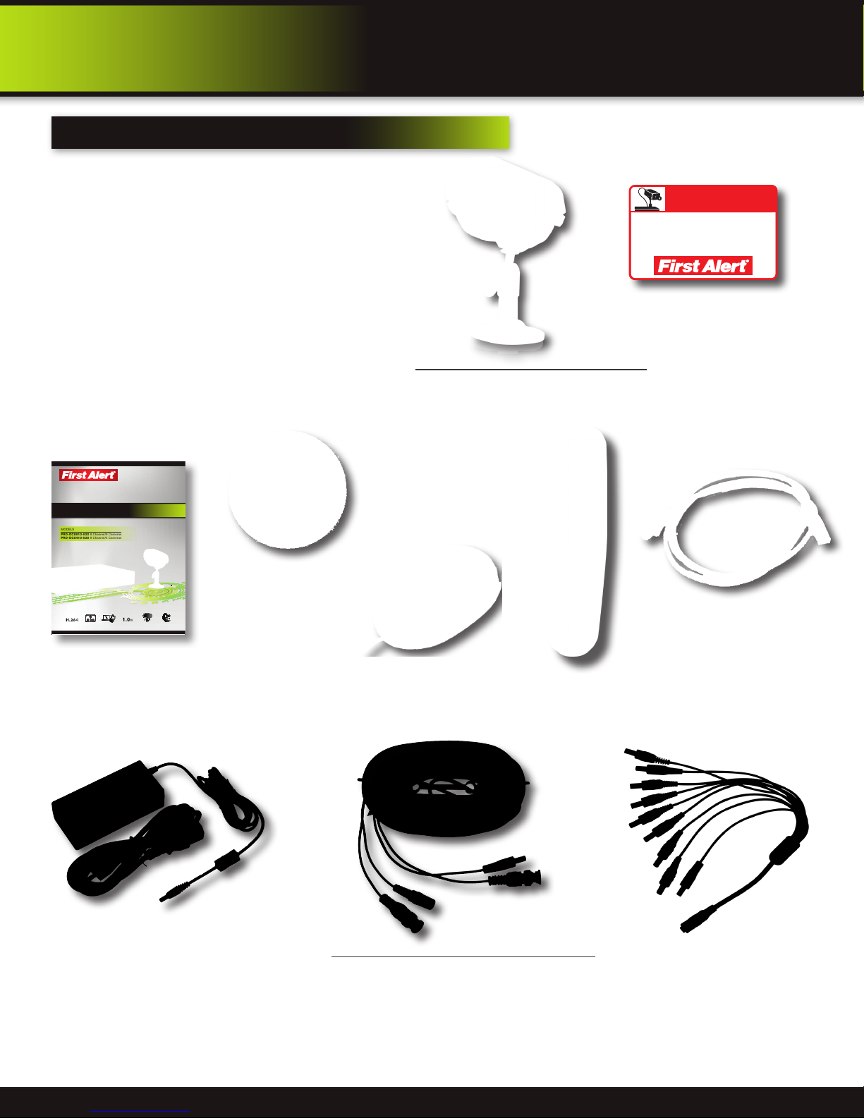
package contents
PRO-D810 H.264
8 Channel Digital DVR
with 1TB Hard Drive
BRK Series
H.264 Digital DVR
quick install guide
MODELS
PRO-DC8810-520 8 Channel/8 Cameras
PRO-DC8410-520 8 Channel/4 Cameras
H.264
COMPRESSION
VIDEO
1.0TB
DVR OPTIMIZED
INDOOR/OUTDOOR
DIGITAL DVR
MOBILE PHONE/
RECORDER
WEB READY
NIGHT
SATA HDD
520 TVL CAMERAS
VISION
Quick Install Guide
Installation Software
and Manuals
PRO-CM520 520 TVL Camera
PRO-DC8810-520: 8 Cameras
PRO-DC8410-520: 4 Cameras
USB Mouse
Remote Control
WARNING
THESE PREMISES ARE UNDER
24 HOUR VIDEO SURVEILLANCE
PROTECTED BY
2 Window
Warning Decals
RJ45 Ethernet Cable
(cable color may be
different)
Power Supply for
DVR and Cameras
60’ BNC Video & DC Power Cable
PRO-DC8810-520: 8 Cables
PRO-DC8410-520: 4 Cables
Page 7
9-way Power splitter -
8 cameras, 1 DVR
product overview
dvr controls
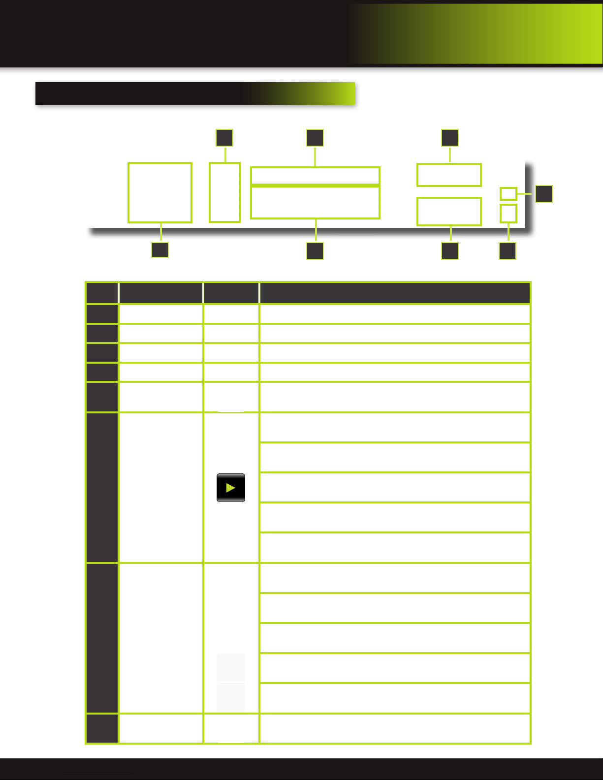
Front Panel
4 3
7
Item Function Control Description
1
Standby Press to enter standby mode
2
IR Sensor IR receiver for the remote control
3
MENU/EXIT Press to open/close the main menu
4
LED Indicators Shows status of Link, 100M, Full, Alarm, Record, HDD.
5
Channel Numbers
Press buttons 1~8 to view the selected channel in full-screen. Pressing
9 returns screen to 8 camera display mode.
6
2
5
8
1
During playback,
6
press the following:
Navigation/OK/PTZ
(Select direction
7
arrow, then press OK
to start PTZ motion)
Increase reverse playback speed 2X, 4X, 8X
Press to freeze playback to one frame, then press again to advance
frame-by-frame
Press to start playback
Press to slow playback speed by 1/2, 1/4, 1/8
Press to increase forward playback speed 2X, 4X, 8X
In menus, press to confirm selections; in PTZ mode, press to change the
navigation buttons to control the connected PTZ camera (not included)
Press to move cursor up; in PTZ mode, press to pan camera up
Press to move cursor down; in PTZ mode, press to pan camera down
Press to move cursor left; in PTZ mode, press to pan camera left
Press to move cursor right; in PTZ mode, press to pan camera right
8
USB
Connect a USB flash drive to the left port for data backup and firmware
upgrades. Connect a USB mouse to the right port
Page 8
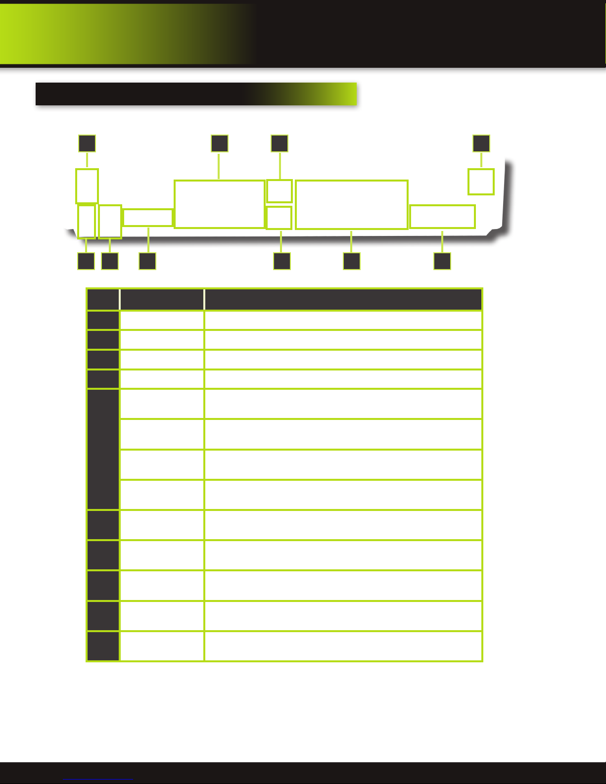
back Panel
product overview
dvr controls
9 10
21
Item Function Description
1
POWER Input DC 12V/5A power connection
2
Network For connecting RJ45 ethernet cable to PC or router
3
VGA Output For connecting to a VGA monitor
4
Video Output For connecting to a BNC monitor (800 x 600) - NTSC or PAL
Alarm Input 8 alarm inputs
76
543 8
Alarm Output Output for alarm
5
RS485 For connecting PTZ cameras
+12V
6
Audio Input
7
Audio Output For connecting audio signal to amplified speakers (RCA jacks)
8
Video Input For connecting video signal from cameras (BNC)
9
Power Switch Power On/Off
10
Ground Ground connection
Power supply for alarm block inputs, the current is 100mA (to prevent
short circuits)
For connecting audio signal from audio capable cameras or self powered
microphones (RCA jacks)
Page 9
product overview
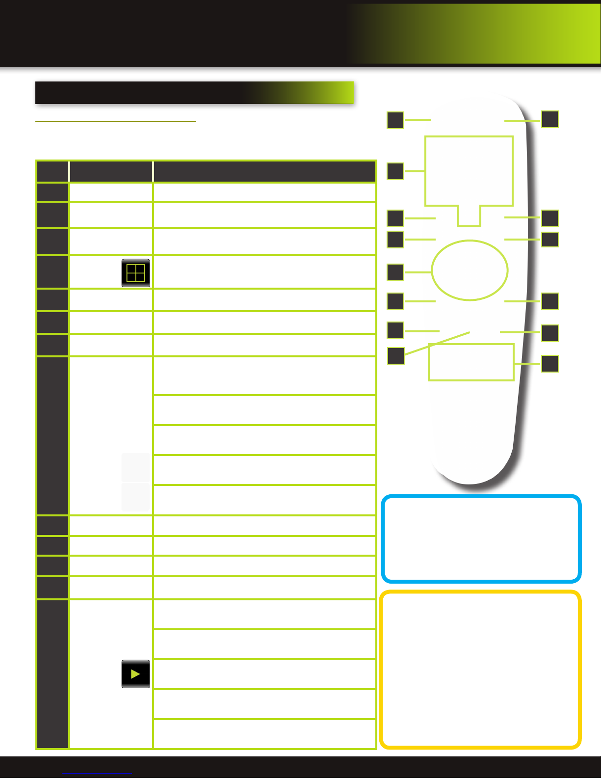
remote control
remote control
Remote Control Operation
The remote control is the secondary input device for navigating the system’s
interface. In device operation, the OK key has the same function as “left click” of
the mouse.
Item Function Description
1
STANDBY Press to turn standby mode ON/OFF
2
LOGIN/LOCK
Number/Channel
3
Buttons
Window
4
Display
5
MENU Opens the main menu
6
PTZ Press to open the PTZ control window
7
EXIT Close menu windows
Navigation/
8
OK
If “Security” has been enabled in the setup menu, press to
open the user password login screen or log off system.
While in menus, press buttons 0~9 to enter values; during
live viewing, press to view channels in full-screen
Press to switch between quad and split-screen displays
In menus, press to confirm selections; in PTZ mode, press
to change the navigation buttons to control the connected
PTZ camera (not included)
Press to move cursor up; in PTZ mode, press to pan
camera up
Press to move cursor down; in PTZ mode, press to pan
camera down
3
6
8
9
10
1
11
2
54
7
9
12
13
Press to move cursor left; in PTZ mode, press to pan
camera left
Press to move cursor right; in PTZ mode, press to pan
camera right
9
+ / - In menus, press to adjust values
10
RECORD Press to start manual recording
11
STOP Press to stop manual recording
12
EXTRA For future use
Increase reverse playback speed 2X, 4X, 8X
Press to freeze playback to one frame, then press again to
advance frame-by-frame
Playback
13
Controls
Press to start playback
Press to slow playback speed by 1/2, 1/4, 1/8
Press to increase forward playback speed 2X, 4X, 8X
Remote Control
TIP: When using the remote
control to enter password
and camera titles, select the
field using the navigation
buttons, press ENTER, and then press the
number buttons.
Battery Replacement Instructions for Use
Always purchase the correct
size and grade of battery most
suitable for intended use. Re-
place all batteries of a set at
the same time. Clean the battery contacts
and also those of the device prior to battery
installation. Ensure the batteries are installed
correctly with regard to polarity (+ and -). Remove batteries from equipment that is not to
be used for an extended period of time. Remove used batteries promptly.
Page 10

pRODUCT oVERVIEW
MOUSE and virtual Keypad
MOUSE controls
Mouse Operation with this DVR
The mouse is the primary input device for navigating system
menus.
NOTE: Unless otherwise noted, all system functions described in
this manual are achieved through mouse input.
To use a mouse with the system:
Connect a USB mouse to the USB MOUSE port on front panel of
the system.
NOTE: Only the USB 2.0 port on the front panel is designed for
data backup to a USB flash drive. Do not connect a USB flash
drive to the USB MOUSE port.
Use the mouse buttons to perform the following:
Left-Button:
1
• Click to select a menu option
• During live viewing in split-screen double-click on a
channel to view the selected channel in full-screen
• Double-click the channel again to return to split-screen
view
• Selecting letter or number on the virtual keypad
DVR Front Face
Connect Mouse &
USB Drive
Right-Button:
2
• Click to open the Quick Access Menu
• Exits any window
• Exits any menu or re-opens previous menu
Scroll-Wheel:
3
• Forward-switch to VGA; backward-switch to BNC (CVBS)
Virtual Keypad
Virtual Keypad
To enter text or numerical data, the system uses a virtual
keypad. In fields where letters or numbers can be entered, you
can switch between various formats – numbers, upper case
(ABC) and lower case (abc). Note you can access all numbers
when in the “Letters” virtual keypads. See below.
2
3
1
Mouse Button Operation
Numbers
Letters-Uppercase
Letters-Lowercase
Page 11
product overview
cAMERA AND pOWER cONNECTIONS
Installing cameras
Mounting Cameras and Running Cable
Select the position for the camera and secure the camera stand. Screw the
camera onto the stand. Adjust camera to the proper view angle. Make sure
the lens is upright relative to the subject. Tighten the thumb bolt. First Alert
cameras can be either ceiling or wall mounted by simply reversing the camera
stand mounting. See “Camera Orientation” Info box. Holes are provided on
both the bottom and back of the camera housing
to accommodate most mounting requirements.
Attach proper length of cable and run from
camera to DVR location. Note: Power cable ends
are different. Be sure the correct power connector
end matches “To Camera” or “To DVR”. Tip Connect cable at camera end before running
cable to verify orientation is correct. Also, see
Information box on “Longer Cable Runs”.
To DVR To Camera
Verify Cable Orientation
Camera - Wall Mounted
Camera - Ceiling Mounted
Longer Cable Runs
Longer cable runs may require an upgrade to RG59 Coax cable. First Alert kits ship
with economical AV cable that is designed to work well up to the length of cable
provided, usually around 60 feet. If longer distances between camera and DVR are
required, you will need to upgrade to RG59 Coax cable. We provide several lengths
may require fire rated cable, FT-4/CMR UL approved for in-wall installations.
up to 300 feet. In addition, if you need to run cable for in-wall installations, then you
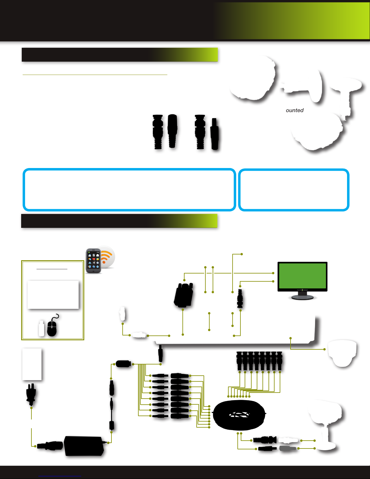
connecting devices
Follow this diagram to make device connections. Note, some devices are
not included with this kit. See “What’s in the Box” for included devices.
RCA Audio In from Audio
Cameras or Powered
Microphone
(Not included)
DVR Front Face
Connect Mouse &
USB Drive
Smartphone
through Mobile
Internet Setup
(Smartphone Not
included)
RJ45 Ethernet
to Router and
Internet
Camera Orientation
It’s important the camera is
mounted correctly to ensure the
image is not upside down as the
camera lens can only be positioned one way.
RCA Audio Out to
Powered Speakers
(Not included)
VGA to PC Monitor or TV
BNC to Security Camera Monitor
(Not included)
Splitter 8 camera/
1 Power
Power
from 120V
DC Converter - 12V
Power to DVR
Power to Cameras
Page 12
PTZ & Alarm
Connections
(Cameras not
included)
Video to DVR
Channels 1-8
AV Cable: BNC/
DC Power
(1 per Camera)
Video to Camera
Power to Camera

system operation
system start up
Default Video Output
The default video output for the DVR system is VGA. If you connect a BNC (CVBS)
monitor on initial setup, you will need to use the mouse “Scroll Wheel” to switch to
the BNC output to be able to use the mouse. Roll the mouse “Scroll Wheel” backward to go to BNC and forward to go to VGA. The REMARK screen is shown on
startup.
Power On/Off
To power the system On/Off, connect the power
cable to the DC 12V port on the rear panel. Flip
the toggle switch on in the back of the DVR. At
startup, the system performs a basic system
check and runs an initial loading sequence. After
a few moments, the system loads a live display
view.
initial setup
Switch between VGA to BNC Output
Power Switch
Standby Mode
The system can also be put into Standby Mode. Power will remain to the system but
will not be recording. To start/stop Standby Mode:
1. Press and hold the POWER button on the front panel or remote control until the
prompt closes. The system enters standby mode. You can also enter Standby
mode through the Quick Access Menu. See next page.
2. To exit standby mode, press and hold the POWER button on the front panel or
remote control until the system beeps. The system will begin powering up.
User Login
Password
ATTENTION: By default, passwords are disabled on the system. You do not need
to enter a password when accessing any system menus. However, for security
purposes, it is highly recommended to enable passwords on the system using
the Password Menu. See “Password” section for details on setting up passwords.
Click APPLY to access the menus or click EXIT to cancel password setup and
return to the LIVE VIEW screen.
Standby Mode
User Login Menu
Page 13

initial setup
system operation
Live View Screen
The Live View Screen is the home or main viewing screen. It shows live video of all current
cameras connected to the DVR. You can double-click a channel at any time to view it
in single-channel mode. You access all menus from this Live View screen via the Quick
Access Menu. You will also see the Channel number or name, time and day information
(see page 16 “Camera Display Setup” for customizing the Live View Screen). It is also
where you will see various information and warning icons, depending on what is happening
in the system or with the alarms that may be set.
】 means the channel is recording
【R
】 means motion detection alarm activated on the channel
【M
】 means an input on the alarm block activated on the channel
【I
】 means either the hard drive is not installed, it is bad or it is full
【H
】 means Tamper Alarm has been activated on the channel
【B
Quick Access Menu
When using the mouse, use the Quick Access Menu to access several system options, including the Main Menu. Select one of the following options:
• MAIN MENU: Opens the main system menu
• KEYLOCK: Logs current user off the system. Re-login required.
• CHN SWITCH: Select type of split-screen display
• VIDEO SEARCH: Open the Search Menu to view recorded video
• PTZ : Opens the PTZ control menu
• MUTE: Mute listen-in audio on the system. Recording of audio is still enabled.
• MANUAL REC: Start manual recording
• STOP REC: Stop manual recording
• ROTATION: Sets the time each channel is visible when rotating through chan-
nels. The Loop Time in seconds is set in the Video Setup Screen.
• START CRUISE: Click to start preset PTZ Camera motion
• STOP CRUISE: Click to stop preset PTZ Camera motion
• STANDBY: Puts system in standby mode.
Quick Access Menu
To close the Sub-Menu, left click anywhere on-screen.
Main Viewing Screen
Showing No HDD in DVR
Main Menu Access
To open the Main Menu: Right-click anywhere on-screen to open the Quick Access Menu and select MAIN MENU (mouse only), or
press the MENU button on the remote control or front panel of the system.
NOTE: If passwords are enabled on the system, you need to select your Device ID and enter the 6-digit numerical password to open
the Main Menu.
Main Menu
1. RECORD SEARCH: Search for recorded video on the system.
2. RECORD: Configure recording parameters (quality, resolution), set record
modes, and enable/disable audio recording. Note: Audio capable cameras
(not included) are required for audio recording on the system.
3. HDD: Display hard drive status and format the internal hard drive of the system.
4. BASIC: Open the Basic Setup Menu, which lets you set the system language,
date and time, device IDs and passwords, and configure display, audio and
video settings.
5. ADVANCED: Opens the Advanced Setup Menu, which lets you view system
info, configure alarm, PTZ, motion detect, maintenance, mobile, and network
settings.
6. EXIT: Closes the Main Menu.
7. Displays information about the contents of the selected Main Menu icon.
No HDD installed
NOTE: If there is no HDD installed, or the HDD is not recognized, or the HDD is not formatted in Live
View a red【H】will be displayed in the video preview interface. You must format the HDD in the DVR
before first use. See: Menu > HDD management > Format. After formatting, the system will restart.
Main Menu
Page 14

initial setup
system operation
Password Setup
Setting Up Passwords & User Permissions
When you first startup your DVR, you are automatically logged in as the ADMIN under Device ID: 000000. By default, passwords
are disabled on the system. You will not need a password to log in or access menus. You will not need a password to access your
system using the browser-based remote software.
The system employs two levels of user authorities connected to a Device ID. The levels are as follows:
1. ADMIN (administrator): Has full control of the system, and can change both administrator and user passwords and enable/
disable password checking
2. USER (normal user): Only has access to live viewing, search, playback, and other limited authorities.
For security reasons, it is highly recommended to enable passwords on your system. If you enable passwords, you must select an 1-8 digit ADMIN password and a
1-8 digit USER password. The ADMIN and USER passwords must not be the same.
If you forget your password, contact First Alert Consumer Affairs for help in resetting. For your security you will be required to verify proof of ownership by providing
a notarized letter. See BRK website for the “Notarized Statement Of Ownership
For Security System Override Pass Codes” form to be completed.
To customize PASSWORD settings, click BASIC from the Main Menu, then click
PASSWORD. You are now in the User Setup menu. From here you can change the
DEVICE ID. Note this is not a required for a basic setup:
1. Device ID: Click the field beside Device ID and enter a 6-digit numerical Device
ID using the Virtual Keyboard.
Next, in the USER SETUP Menu click CONFIG to set up users. NOTE: Only the Administrator can enter the CONFIG setup. You can change the
• STATE: active or not (Note for User Set #1, ADMIN, the STATE of ACTIVE or
INACTIVE cannot be changed.)
• USER NAME: Assign or change user name using the virtual keyboard.
• PASSWORD ENABLE: enable or disable the password for this user
• PASSWORD: Password must be 1-8 digits
• CONFIRM: confirm the password
• PERMISSION: Select all permissions for this user. (NOTE: this option is not
available for ADMIN as they have all permissions). Available choices are:
Record Setup, HDD Manage, Language Setup, Time Setup, Start/Stop Record,
Display Setup, Alarm Setup, System Info, Motion Detect, Mobile Setup, System
Setup, PTZ Setup, Network Setup, Video/Audio Set, IE Preview for each of 8
Channels, Playback for each of 8
Channels.
Navigate the PERMISSION
Screens by:
• NEXT: Moves to next selecting
page.
• ALL: Selects all permissions.
• CLEAN: Clears all permissions.
NOTE: This page is working
for administrator. Administrator can assign permissions for
user. User just can see but can
not change their permissions.
User Setup
User Password Setup
Multi User Login
After Users are set up, Select active user from USER NAME drop down box to log on with previously set up permissions. The active user(s) will be available. Next, key in the device ID and
user password.
User Login-Multi Users
User Permission Screen 1
Page 15
User Permission Screen 2
 Loading...