

Page 1
Pro Series
H.264 Digital DVR
quick install guide
MODELS
PRO-DC8810-520 8 Channel/8 Cameras
PRO-DC8410-520 8 Channel/4 Cameras
H.264
VIDEO
COMPRESSION
DIGITAL DVR
RECORDER
MOBILE PHONE/
WEB READY
1.0TB
DVR OPTIMIZED
SATA HDD
INDOOR/OUTDOOR
520 TVL CAMERAS
NIGHT
VISION
Page 2
product overview
product overview
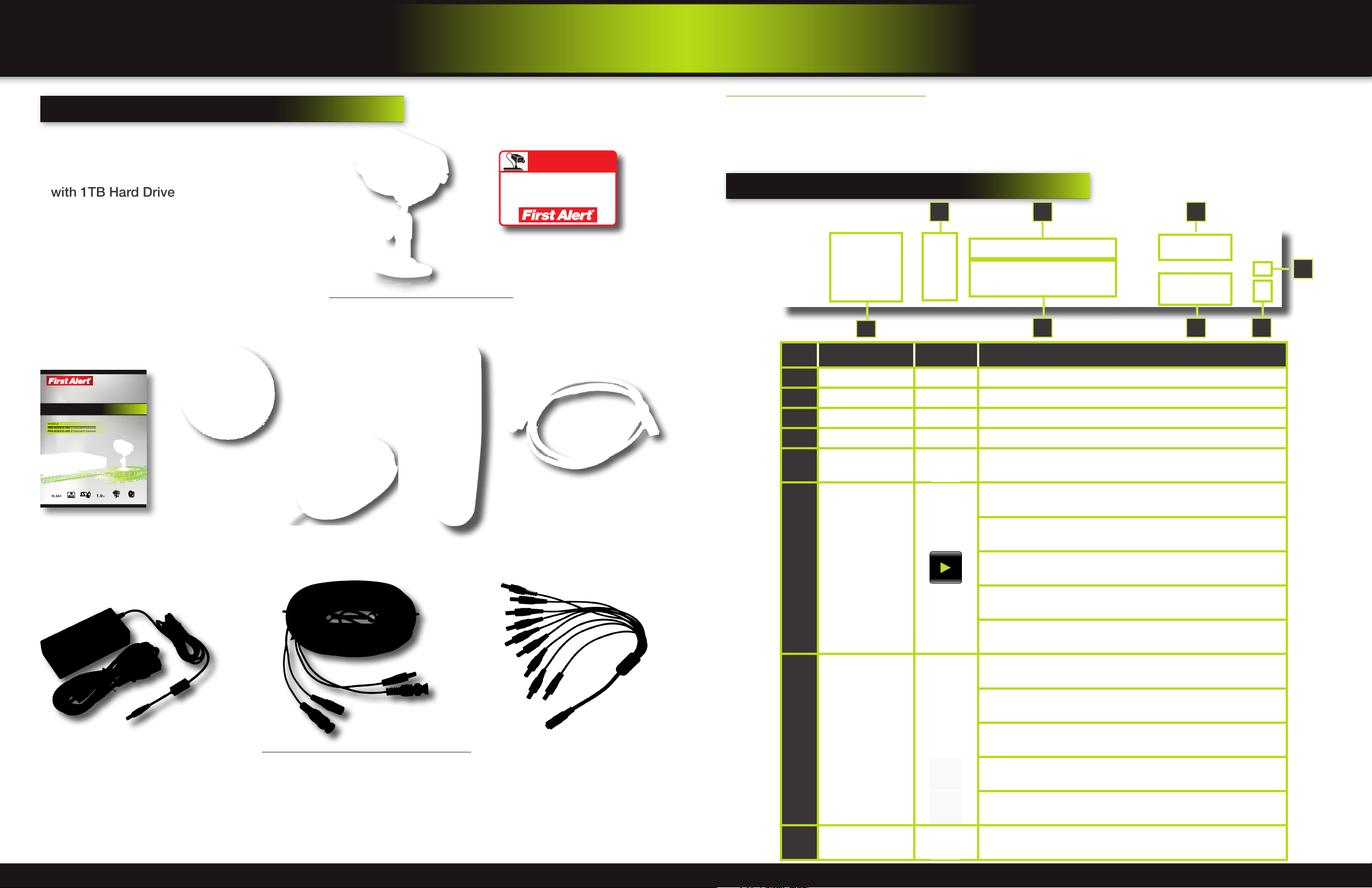
package contents
,
What
PRO-D810 H.264
8 Channel Digital DVR
with 1TB Hard Drive
s in the box
PRO-CM520 520 TVL Camera
PRO-DC8810-520: 8 Cameras
PRO-DC8410-520: 4 Cameras
WARNING
THESE PREMISES ARE UNDER
24 HOUR VIDEO SURVEILLANCE
PROTECTED BY
2 Window
Warning Decals
dvr controls
About this Quick Start Guide
Thank you for choosing First Alert for your security needs! This Quick Start Guide is designed to provide you with the basic
operation of your PRO-D810 DVR which is included in the PRO-DC8810-520 and the PRO-DC8410-520 security kits. Please
consult the complete User’s Manual included on the CD disk for a detailed explanation of all the features and functions of
this DVR. We also encourage you to visit our website at www.brkelectronics.com to check for the latest manuals (English and
Spanish), firmware updates, downloads, other security camera products and announcements. You’ll find this product line under
Products >> Security Cameras >> Wired Cameras.
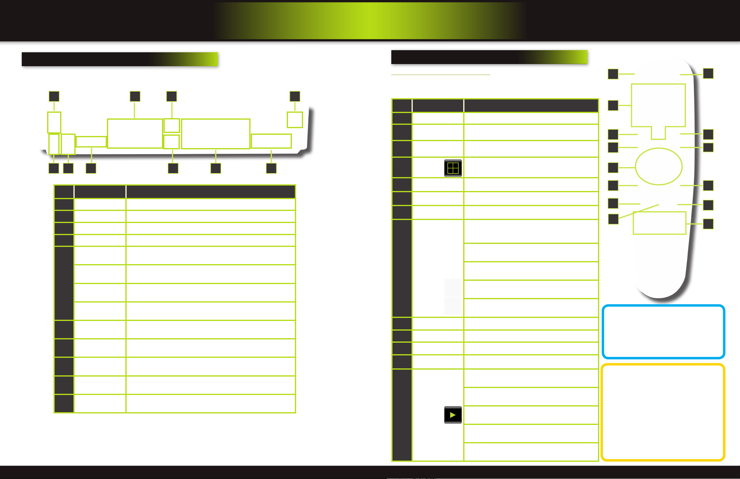
Front Panel
64 3
2
7
Item Function Control Description
1
Standby Press to enter standby mode
5 8
1
Pro Series
H.264 Digital DVR
quick install guide
MODELS
PRO-DC8810-520 8 Channel/8 Cameras
PRO-DC8410-520 8 Channel/4 Cameras
H.264 1.0TB
COMPRESSION
VIDEO
DIGITAL DVR
RECORDER
MOBILE PHONE/
WEB READY
INDOOR/OUTDOOR
NIGHT
7200 RPM
520 TVL CAMERAS
VISION
SATA HDD
Quick Install Guide
Power Supply for
DVR and Cameras
Installation Software
and Manuals
60’ BNC Video & DC Power Cable
PRO-DC8810-520: 8 Cables
PRO-DC8410-520: 4 Cables
USB 2.0 Mouse
Remote Control
RJ45 Ethernet Cable
(cable color may be
different)
9-way Power splitter -
8 cameras, 1 DVR
2
IR Sensor IR receiver for the remote control
3
MENU/EXIT Press to open/close the main menu
4
LED Indicators Shows status of Link, 100M, Full, Alarm, Record, HDD.
Channel Numbers/
5
Playback
Press buttons 1~8 to view the selected channel in full-screen
Increase reverse playback speed 2X, 4X, 8X
Press to freeze playback to one frame, then press again to advance
frame-by-frame
During playback,
6
press the following:
Press to start playback
Press to slow playback speed by 1/2, 1/4, 1/8
Press to increase forward playback speed 2X, 4X, 8X
In menus, press to confirm selections; in PTZ mode, press to change the
navigation buttons to control the connected PTZ camera (not included)
Press to move cursor up; in PTZ mode, press to pan camera up
Navigation/OK/PTZ
(Select direction
7
arrow, then press OK
Press to move cursor down; in PTZ mode, press to pan camera down
to start PTZ motion)
Press to move cursor left; in PTZ mode, press to pan camera left
©2012 BRK Brands, Inc. All rights reserved. Distributed by BRK Brands, Inc. 3901 Liberty Street Road, Aurora, IL 60504-8122. Due to continuing
product development, the product inside the packaging may look slightly different than the one on the package. BRK Brands, Inc. is a subsidiary
of Jarden Corporation (NYSE: JAH). To obtain warranty service, contact the Consumer Affairs Division at 1-800-323-9005, Monday through Friday,
7:30 a.m. - 5 p.m., Central Standard Time. www.brkelectronics.com
Made in China
Page 2 Page 3
Press to move cursor right; in PTZ mode, press to pan camera right
8
USB
Connect a USB flash drive to the left port for data backup and firmware
upgrades. Connect a USB mouse to the right port
Page 3
product overview
product overview
dvr controls
back Panel
9 10
21
Item Function Description
1
POWER Input DC 12V/5A power connection
2
Network For connecting RJ45 ethernet cable to PC or router
3
VGA Output For connecting to a VGA monitor
4
Video Ouput For connecting to a BNC monitor (800 x 600)
Alarm Input 8 alarm inputs
Alarm Output Output for alarm
5
RS485 For connecting PTZ cameras
DVR controls
remote control
Remote Control Operation
The remote control is the secondary input device for navigating the system’s
interface. In device operation, the OK key has the same function as “left click” of
76
543 8
the mouse.
Item Function Description
1
STANDBY Press to turn standby mode ON/OFF
2
LOGIN/LOCK
Number/Channel
3
Buttons
Window
4
Display
5
MENU Opens the main menu
6
PTZ Press to open the PTZ control window
7
EXIT Close menu windows
Navigation/
8
OK
If “Security” has been enabled in the setup menu, press
to open the user password login screen or log off system.
While in menus, press buttons 0~9 to enter values; during
live viewing, press to view channels in full-screen
Press to switch between quad and split-screen displays
In menus, press to confirm selections; in PTZ mode, press
to change the navigation buttons to control the connected
PTZ camera (not included)
Press to move cursor up; in PTZ mode, press to pan
camera up
Press to move cursor down; in PTZ mode, press to pan
camera down
Press to move cursor left; in PTZ mode, press to pan
camera left
1
3
6
8
9
10
11
2
54
7
9
12
13
+12V
6
Audio Input
7
Audio Output For connecting audio signal to amplified speakers (RCA jacks)
8
Video Input For connecting video signal from cameras (BNC)
9
Power Switch Power On/Off
10
Ground Ground connection
Power supply for alarm block inputs, the current is 100mA (to prevent
short circuits)
For connecting audio signal from audio capable cameras or self powered
microphones (RCA jacks)
Page 4 Page 5
Press to move cursor right; in PTZ mode, press to pan
camera right
9
+ / - In menus, press to adjust values
10
RECORD Press to start manual recording
11
STOP Press to stop manual recording
12
EXTRA For future use
Increase reverse playback speed 2X, 4X, 8X
Press to freeze playback to one frame, then press again to
advance frame-by-frame
Playback
13
Controls
Press to start playback
Press to slow playback speed by 1/2, 1/4, 1/8
Press to increase forward playback speed 2X, 4X, 8X
Remote Control
TIP: When using the remote
control to enter password
and camera titles, select the
field using the navigation
buttons, press OK, and then press the number buttons.
Battery Replacement Instructions for Use
Always purchase the correct
size and grade of battery most
suitable for intended use. Re-
place all batteries of a set at
the same time. Clean the battery contacts
and also those of the device prior to battery
installation. Ensure the batteries are installed
correctly with regard to polarity (+ and -). Remove batteries from equipment that is not to
be used for an extended period of time. Remove used batteries promptly.
Page 4
initial setup
initial setup
camera and power connections
step 1 ... Installing cameras
Mounting Cameras and Running Cable
Select the position for the camera and secure the camera stand. Screw the camera onto the stand. Adjust camera to the proper
view angle. Make sure the lens is upright relative to the subject. Tighten the thumb bolt. First Alert cameras can be either ceiling or
wall mounted by simply reversing the camera stand mounting. See “Camera Orientation” Info box. Holes are provided on both the
bottom and back of the camera housing to accommodate most mounting requirements. Run cable from camera to DVR location.
See Information box below on “Longer Cable Runs”.
Camera Orientation
It’s important the camera is mounted correctly to
ensure the image is not upside down as the camera lens can only be positioned one way.
Longer Cable Runs
Longer cable runs may require an upgrade to
RG59 Coax cable. First Alert kits ship with eco-
Camera - Wall Mounted
Camera - Ceiling Mounted
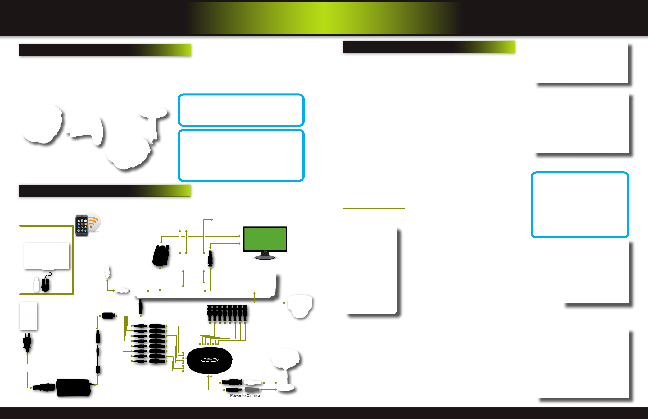
Step 2 ... connecting devices
Follow this diagram to make device connections. Note, some devices are
not included with this kit. See “What’s in the Box” for included devices.
RCA Audio In from Audio
Cameras or Powered
Microphone
(Not included)
Power to DVR
Power to Cameras
DVR Front Face
Connect Mouse &
Power
from 120V
Smartphone
through Mobile
Internet Setup
(Smartphone Not
included)
USB Drive
RJ45 Ethernet
to Router and
Internet
Splitter 8 camera/
1 Power
DC Converter - 12V
DVR are required, you will need to upgrade to RG59 Coax cable. We
provide several lengths up to 300 feet. In addition, if you need to run
cable for in-wall installations, then you may require fire rated cable,
FT-4/CMR UL approved for in-wall installations.
nomical AV cable that is designed to work well up
to the length of cable provided, usually around
60 feet. If longer distances between camera and
RCA Audio Out to
Powered Speakers
(Not included)
VGA to PC Monitor or TV
BNC to Security Camera Monitor
AV Cable: BNC/
DC Power
(1 per Camera)
Video to Camera
Power to Camera
Power to Camera
(Not included)
PTZ & Alarm
Connections
(Cameras not
included)
Video to DVR
Channels 1-8
system operation
Step 3 ... system start up
Power On/Off
To power the system On/Off, connect the power cable to the DC 12V port on the rear
panel. Flip the toggle switch on in the back of the DVR. At startup, the system performs
a basic system check and runs an initial loading sequence. After a few moments, the
system loads a live display view.
Default Video Output
The default video output for the DVR system is VGA. If you connect a BNC
(CVBS) monitor on initial setup, you will need to use the mouse “Scroll Wheel”
to switch to the BNC output to be able to use the mouse. Roll the mouse “Scroll
Wheel” backward to go to BNC and forward to go to VGA. The REMARK screen
is shown on startup.
Password
ATTENTION: By default, passwords are disabled on the system. You do not need
to enter a password when accessing any system menus. However, for security
purposes, it is highly recommended to enable passwords on the system using
the Password Menu. See “Password” section for details on setting up passwords.
Click APPLY to access the menus or click EXIT to cancel password setup and
return to the LIVE VIEW screen.
Standby Mode
The system can also be put into Standby Mode. Power will remain to the system but
will not be recording. To start/stop Standby Mode:
1. Press and hold the POWER button on the front panel or remote control until the
prompt closes. The system enters standby mode. You can also enter Standby
mode through the Quick Access Menu. See below.
2. To exit standby mode, press and hold the POWER button on the front panel
or remote control until the system beeps. The system will begin powering up.
Main Menu Access
To open the Main Menu: Right-click anywhere on-screen to open the Quick Access
Menu and select MAIN MENU (mouse only), or press the MENU button on the remote
control or front panel of the system.
Quick Access Menu
When using the mouse, use the Quick Access Menu to access several system options, including the Main Menu. Select one of the following
options:
• MAIN MENU: Opens the main system menu
• KEYLOCK: Logs current user off the system. Re-login required.
• CHN SWITCH: Select type of split-screen display
• VIDEO SEARCH: Open the Search Menu to view recorded video
• PTZ : Opens the PTZ control menu
• MUTE: Mute listen-in audio on the system
• MANUAL REC: Start manual recording
• STOP REC: Stop manual recording
• ROTATION: Video rotation
• START CRUISE: Click to start preset PTZ Camera motion
• STOP CRUISE: Click to stop preset PTZ Camera motion
To close the Sub-Menu, click anywhere on-screen.
Quick Access Menu
NOTE: If passwords are enabled on the system, you need to select your Device ID and enter the 6-digit numerical password to open
the Main Menu.
Main Menu
1. RECORD SEARCH: Search for recorded video on the system.
2. RECORD: Configure recording parameters (quality, resolution), set record
modes, and enable/disable audio recording. Note: Audio capable cameras (not
included) are required for audio recording on the system.
3. HDD: Display hard drive status and format the internal hard drive of the system.
4. BASIC: Open the Basic Setup Menu, which lets you set the system language,
date and time, device IDs and passwords, and configure display, audio and
video settings.
5. ADVANCED: Opens the Advanced Setup Menu. You can view system info, configure alarm, PTZ, motion detect, maintenance, mobile, and network settings.
6. EXIT: Closes the Main Menu.
7. Displays information about the contents of the selected Main Menu icon.
Switch between VGA to BNC Output
User Login Menu
No HDD installed
NOTE: If there is no HDD
installed, or the HDD is
not recognized, or the
HDD is not formatted
it will display a red【H】in the video
preview interface. You must format the
HDD in the DVR before first use. See:
Menu > HDD management > Format.
After formatting, the system will restart.
Main Viewing Screen
Showing No HDD in DVR
Main Menu
Page 6 Page 7
Page 5
initial setup
initial setup
system operation
Step 4 ... language, date and time
Setting Up Language/Date/Time
Set the system language, date and time, passwords, and configure audio and display options. The Basic Setup Menu contains the following sub-menus: Language,
Date/Time, Password, Display, and Video/Audio.
Language
To change the system language:, from the drop-down menu select LANGUAGE.
Click APPLY. Click CLOSE in the confirmation window. Click EXIT to close the
menu.
NOTE: The system will restart when you finish system language setup. The
default is English.
Mountain: -7
Western: -8
Alaska/Hawaii: -9 through -11
System Language Menu
Date/Time
It is highly recommended to immediately set the date and time when first setting
up your system. To set the date and time:
1. Click DATE/TIME and configure the following options:
• DATE: Enter the day, month, and year.
• DATE FORMAT: Select DD/MM/YYYY, MM/DD/YYYY, or YYYY/MM/DD
• TIME: Enter the time
• TIME FORMAT: Use the drop-down menu and select 12HOURS or
24HOURS. If 12HOURS is selected, then set AM or PM.
• DST: Use the drop-down menu to select ON/OFF to enable/disable Daylight Savings Time. See below for details on setting DST.
2. Click ZONE to enter your time zone from -12 to +12. To find your time zone
visit www.worldtimezone.com or other similar sites.
See Info box for US codes.
3. Click SAVE DATE AND TIME. The new date and time are saved. Click EXIT.
Basic Setup Menu
US World Time Zones - UTC Codes
UTC stands for Universal Time Coordinates
or Greenwich Mean Time (GMT)
Eastern: -5
Central: -6
System Time/Date Setup
system operation
Step 5 ... camera display setup
Setting Up Cameras for Viewing and Recording
Use the Display Setup menu to customize channel titles, show/hide the date and time in live viewing and playback, and enable/
disable preview channels. To customize Display settings, click BASIC from the Main Menu, then click DISPLAY:
Display
1. Configure the following options:
• NAME: Click any of the fields and enter a new title for the selected
channel using the Virtual Keyboard (mouse only)
• POSITION: Reposition the channel title; select TOPLEFT, BOTTOMLEFT, TOPRIGHT, BOTTOMRIGHT, or OFF. If OFF, the title will not be
displayed for the selected channel
• COLOR: Adjust CHROMATICITY, LUMINOSITY, CONTRAST, and SATURATION for the selected channel
• LIVE: This feature can be very useful if your display monitor is in public
view. With LIVE in the OFF selection that channel will appear black on
the display to give the impression that no cameras are connected and
the system is not recording. Select ON/OFF to enable or disable this
feature
• PREVIEW TIME: Select ON/OFF to show/ hide the date and time during
live viewing
• RECORD TIME: Select ON/OFF to show/hide the date and time during
playback.
2. Scroll down to change the settings for the remaining channels
3. Click APPLY to save your settings. Click OK in the REMARK window. Click
EXIT.
Video/Audio
Use the Video/Audio menu to set the resolution and camera setup
on the system. To configure Video/Audio options:
1. Under VGA RESOLUTION, select 800 x 600, 1024 x 768, 1280 x 1024,
1366 x 768, 1440 x 900.
2. Under CAMERA SYSTEM, select NTSC or PAL. (See info box below)
3. Under LOOP TIME (SECOND), enter with virtual keypad from 1 to 300
4. Under VOLUME SETUP, adjust slider from 0 to 63. Click X to save.
5. Under MARGIN, adjust TOP, BOTTOM, LEFT, RIGHT margin with slider from
0 -10. Also adjust Display from VGA or CVBS. Default is VGA and 0 for all
margins
6. Click APPLY. Click OK in the REMARK window.
7. Click EXIT in all menus until all windows are closed.
Display Setup Menu
Color Set-up
Daylight Savings Time (DST)
To set daylight savings time:
1. Under DST, select ON. DST options appear.
2. Under DST MODE select one of the following:
• DEFAULT: The Default setting will apply the United States daylight savings time period from the second Sunday of
March to the first Sunday in November (go to step 3)
• CUSTOM: Set customized start and end times for DST (go to step 4)
3. If using the DEFAULT, click APPLY. Click EXIT.
4. If setting a CUSTOM DST, use the drop-down menus to select a week and month for the start and end times.
5. Click APPLY. Click CLOSE in the confirmation window.
6. Click EXIT in each menu until all windows are closed.
Why Set a Date & Time?
It’s important to set the proper date and time before continuing so that you can easily locate recorded events.
Inaccurate dates and times on files may affect their admissibility as evidence in court. In addition, when
changing current time settings, to avoid possible confusion with the time stamps on recorded and currently
recording files, stop all ongoing recording processes before altering the system time and restart recording
using the new settings.
Page 8 Page 9
Audio/Video Recording
Caution: Audio surveillance in some
states is illegal or requires permission from one or both parties to record
someone’s voice. Laws are also different from residential vs. commercial applications.
Some federal, state, and local laws prohibit certain
surveillance activities and/or the use or distribution of
the information obtained from such activities. Prior
to using this system, you should become familiar with
the pertinent laws to ensure compliance with those
applicable to surveillance activities.
Video/Audio Menu
NTSC or PAL?
NTSC (National Television Standards Committee)
is the video system or standard used in North America and most of South America. In NTSC, 30 frames
are transmitted each second. Each frame is made
up of 525 individual scan lines.
PAL (Phase Alternating Line) is the predominant video system or
standard mostly used overseas. In PAL, 25 frames are transmitted
each second. Each frame is made up of 625 individual scan lines.
Page 6
initial setup
initial setup
Basic operation
Basic Setup
Use the BASIC SETUP menu to configure language, date and time settings,
password setup, along with display, video and audio settings. You can also exit
the system through this menu. The Basic Setup menu contains the following
sub-menus: Language, Date/Time, Password, Display, Video/Audio and Exit.
recording
RECORD Mode
Configure Recording Options:
In this Menu you have three recording options: POWER UP (Continuous), TIMER
RECORD (enables SCHEDULE menu) and ALARM (within SCHEDULE menu). By
default, the DVR is set to record continuously. Set parameters as follows:
1. From the Main Menu click RECORD. Under SWITCH, use the drop-down menus
and select ON/OFF to enable/disable recording from the selected channel. Note:
If SWITCH is set to OFF, then Motion Detect, Alarm and Manual Record are also
disabled for that channel.
2. Under RESOLUTION, select CIF, HD1, or D1.
NOTE: NTSC: @30fps, PAL: @25fps. Recording capabilities for both NTSC & PAL:
Channels 1 & 2: D1, HD1, CIF; Channels 3-8: HD1, CIF.
3. BITRATE (Kbps): See table for details.
4. FRAMERATE: Choose the recording frame rate 1-30, (fps – frames per second).
The lower the value, the less life-like and more jerky the recorded movements
will be. However, a lower frame rate uses less HDD space. Make your choice
depending on the precision with which you want to follow the events being
recorded. Frame-rate of each channel can be adjusted but is limited by the total
resources available. The total frame rate for all channels combined cannot exceed
420 (NTSC) fps. Note: Although the chipset is NTSC 480, part of the resources are
used for other internal functions and cannot be allocated to recording resources.
The ratios of D1, HD1 and CIF are as follows: 1 D1= 4 x CIF, 1 HD1 = 2 x CIF.
5. AUDIO, select ENABLE or DISABLE. If audio recording is enabled, the system will
record audio from connected audio capable cameras (not included). See caution statement on audio recording in Video/Audio section.
6. REC. MODE, select POWER UP or TIMER RECORD. If you select POWER UP, the
system will record continuously when the system is powered on. If you select TIMER
RECORD, you have to set a recording schedule on the system.
7. REC. SIZE (Record Size), select 15MIN, 30MIN, 45MIN, or 60MIN.
NOTE: Record Size sets the file size for recorded video files on the system. Instead of recording data as one large file, the system
will divide the data into blocks of 15, 30, 45, or 60 minutes. This makes the recorded data easier to search
8. MASK FIELD lets you block a specific portion of a channel you do not want recorded or shown on the display screen. This can be
useful if you need to conceal a sensitive area being captured by the camera. See next section for details.
9. Click APPLY. Click OK in the REMARK window. Click EXIT.
Recording Schedule (TIMER RECORD)
You can program the DVR to record according to a customized recording schedule.
The Schedule Grid shows the days of the week and hour blocks 00~23. You can set
Alarm Recording (Red), General Recording (Green), or No Recording (Blue) to each
time block of each day. To set a recording schedule:
1. Open the Main Menu and click RECORD.
2. Under REC. MODE, select TIMER RECORD.
3. Click SCHEDULE. The Schedule menu opens.
4. Under CHANNEL, select specific channels or select ALL.
5. Below the grid, click either ALARM (red), GENERAL (Green), or NO RECORD
(Blue) and then click a time block on the desired day.
6. Use the FROM/TO drop-down menus to copy the schedule of one day to
another. For example, if you want your schedule for Monday to be the same on
Wednesday: under FROM select MON, under TO select WED, and then click COPY.
7. Click APPLY. Click OK in the REMARK window. Click EXIT.
CCTV Resolution
CCTV resolution is measured in vertical and horizontal pixel dimensions and typically
limited by the capabilities of both the camera and the recorder that you are using for
your CCTV surveillance installation. CCTV systems use an analog video signal. For
television specifications (which CCTV uses) the highest resolution that can be captured
and stored is 704 x 480 (NTSC for the United States) and 720 x 576 (PAL for Europe). This resolution
is known as D1 resolution. A high end CCTV recorder is capable of recording at up to D1 resolution.
Basic Setup Menu
Record Menu
Bitrate in Kbps
Image
Quality
CIF
HD1
D1
Recording Schedule
Low Medium High
384 512 768
512 768 1024
896 1024 1280
CCTV Resolutions
D1: 704 x 480
HD1 (2CIF): 704 x 240
CIF: 352 x 240
QCIF: 176 x 120
Motion Detect Setup
You can configure motion detection for each channel (Camera) connected to the
DVR. To configure motion detection:
1. From the Main Menu click ADVANCED. Then click MD (Motion Detect).
2. Under STATUS, select ON to enable motion detection for the desired channel. Scroll down for additional channels. Note: If in the RECORD screen a
Channel is set to OFF, MOTION is also disabled for that Channel
3. Under SENSITIVITY, select 1 through 8. The higher the number, the more
sensitive the motion detection.
4. Under MD AREA SETUP, click SETUP. The red motion grid appears over the
selected channel in full screen.
5. Click the blocks in the grid to enable/disable motion detection. Red=motion
detection enabled; Clear=motion detection disabled.
6. Right-click anywhere on the screen to return to the Motion Detection menu.
7. Click EMAIL, then select ON/OFF to turn on e-mail notification. E-mail must
be configured. See manual for details.
8. Click APPLY. Click CLOSE in the confirmation window.
9. Click EXIT in all menus until all windows are closed.
NOTE: You can disable the MD buzzer in the Alarm Setup menu.
step 7... playback
PLAYBACK Mode
View recorded video on the system through the Search Menu. To begin playback:
1. Right-click anywhere on the screen and select VIDEO SEARCH from the
Quick Access Menu. The Search Menu opens.
NOTE: When you first open the Search Menu, it displays the current month
and date.
2. Click PLAY to playback the last minute of recorded video (Quick Search) OR
Under CHN select a specific channel or select ALL.
3. Under DATE, enter a date using the Virtual Keyboard (mouse only).
4. Click SEARCH. Recorded events on the system appear in red (alarm events—
includes both alarm and motion events) and green (normal recording).
5. Click a date in the Month Grid to search for video files.
6. Click a time block in the Hour Grid to view the video. Playback begins.
7. Move the mouse slightly to display the on-screen play back controls. You
can also use the playback control with buttons on the remote control or front
panel of the system.
On-screen Playback Controls
To use the on-screen playback controls:
1. Click the VCR-like controls to play, pause, fast forward, rewind, and
slow down playback.
2. Drag the slider to adjust the volume (audio capable camera required,
not included). Select the box to mute the audio.
3. Click X to quit playback and return to the Search menu.
On-screen Playback Controls
8. Under RECORD STATE, the system shows recorded events in a Month
Grid and a Time Grid. The selected day of the month will be outlined in
red. Green=normal recording; Red=alarm recording (includes both alarm
and motion events). Click a date in the month grid to view recorded video
files for that selected date in the hour grid.
Basic operation
Motion Detect Menu
Motion Detect Grid
Record/Search Menu
Month Grid
Hour Grid
Record State
Page 10 Page 11
Page 7

©2012
BRK Brands, Inc.
a Jarden Corporation Company (NYSE:JAH)
3901 Liberty Street Road, Aurora, IL 60504-8122
Phone: 630-851-7330 Tech Services: 800-323-9005
www.brkelectronics.com
M08-0387-002
 Loading...