

Page 1
BRK Series
H.264 Digital DVR
user,S manual
MODELS
PRO-DC8810-520 8 Channel/8 Cameras
PRO-DC8410-520 8 Channel/4 Cameras
H.264
VIDEO
COMPRESSION
DIGITAL DVR
RECORDER
MOBILE PHONE/
WEB READY
1.0TB
DVR OPTIMIZED
SATA HDD
INDOOR/OUTDOOR
520 TVL CAMERAS
NIGHT
VISION
Page 2

introduction
thank you
Welcome
Thank you for choosing First Alert for your security needs!
For more than half a century, First Alert has made the home-safety and security products that make
your job easier. Our products are built to the highest standard which has earned us a leadership role
in the home-safety and security product categories. We are committed to serving our customers,
from the professionals who install our products, to the families and businesses who count on them.
First Alert has been helping families and businesses stay safe for over 50 years. By having a First
Alert Security System, you’re taking the first step in protecting your home or business from damage
or theft. We’re watching, even when you’re not.
This manual is written for the PRO-D810 DVR which is included in the PRO-DC8810-520 and the
PRO-DC8410-520 security kits. It was accurate at the time it was completed. However, because of our
ongoing effort to constantly improve our products, additional features and functions may have been
added since that time and on-screen displays may change. We encourage you to visit our website at www.
brkelectronics.com to check for the latest manuals (English and Spanish), firmware updates, downloads,
other security camera products and announcements. You’ll find this product line under Products >> Security
Cameras >> Wired Cameras.
©2012 BRK Brands, Inc.
a Jarden Corporation company (NYSE: JAH)
www.brkelectronics.com
All rights reserved. Distributed by BRK Brands, Inc. 3901 Liberty Street Road, Aurora, IL 60504-8122. Due to continuing product development, the
product inside the packaging may look slightly different than the one on the package.
BRK Brands, Inc. is a subsidiary of Jarden Corporation (NYSE: JAH). First Alert® is a registered trademark of the First Alert Trust. To obtain warranty
service, contact the Consumer Affairs Division at 1-800-323-9005, Monday through Friday, 7:30 a.m. - 5 p.m., Central Standard Time.
Made in China
Page 2
Page 3

introduction
key product features
Main Description
Eight channel H.264 digital video recorder with Internet remote surveillance,
motion detection, PTZ and alarm control suitable for applications such as highend residential - new or remodel, light commercial, small business/retail, small
warehouse or small grocery.
Product features
• H.264 Compression & Virus free Linux O/S
• Real hexaplex operation - simultaneous record, playback, mobile phone live
view, backup, control, & remote access
• 1 TB SATA hard drive installed
• Supports smart phone live view & E-mail alarm
• Customizable E-mail alerts
• Supports 8-channel HD1 or 2-channel D1 and 6-channel CIF Real-time
simultaneous recording
• Supports 8-channel simultaneous playback
• User-friendly interface: 16 bit true color, semi-transparent GUI with notes for
selected menu items
• Advanced motion detection activated recording
• 24/7 Scheduled Recording
• Supports D1,HD1,CIF for recording quality
• Network monitoring through internet access
• Supports USB or external DVD backup
• Hi-speed backup/upgrade/record via USB2.0
• PTZ camera control
• CMOS Color 520TVL cameras with 30 IR LED’s for up to 80’ night vision and IP65
weather rating
Page 3
Page 4

introduction
table of contents
section description
1
2
Introduction 2-3
Safety 6
Product Overview 7
What is in the Box 7
DVR Controls
Front Panel 8
3
Back Panel 9
Remote Control 10
Mouse Controls 11
Camera Power Connections 12
Connecting Devices 12
Initial Setup - System Operation 13
System Start Up 13
Default Video Output 13
Power On/Off 13
User Login 13
Live View Screen 14
4
Quick Access Menu 14
Main Menu Access 14
Password Setup and User Permissions 15
Camera Display Setup 16
Display, Video/Audio 16
Language, Date and Time 17
Language, Date/Time and Daylight Savings Time (DST) 17
Page
number
Basic Operation 18
Recording 18
Configure Recording Options 18
Recording Schedule (Timer Recording) 18
Recording Schedule (TIMER RECORD) Example 19
Privacy Mask Field 19
5
Motion Detect Setup 19
Playback 20
Playback and Record Search 20
On-Screen Playback Controls 20
File List 21
Backup 21
HDD Management 21-22
Page 4
Page 5

introduction
table of contents
section description
Advanced Operation 22
Alarm 22-23
Alarm Setup 22-23
E-mail Setup 23
System Info and System Update 24
6
System Maintain 24
Upgrade Firmware 24
PTZ Setup and Control 25-26
Step 1: Connect your PTZ Camera to this DVR 25
Step 2: Configure PTZ Communication Settings 25
Step 3: Configure the Operation and Control of your PTZ Camera(s) 25
Step 4: Configure the CRUISE SETTING of your PTZ Camera 26
Remote Access 27
Network Setup for Remote Access 27
DHCP (Dynamic Host Configuration Protocol) 27
Static IP 27
UPnP (Universal Plug and Play) 28
PPPoE (Point-to-Point Protocol Over Ethernet) 28
DDNS (Dynamic Domain Name Service 29-30
7
Port Forwarding 30
Remote Surveillance 31
Remote Surveillance using Internet Explorer 31-32
Using Remote Surveillance 32
Remote Surveillance Main Screen 33
Live Viewing Tab 34
Playback Tab 35-36
Setup Tab 37
Setting, Maintenance and Host Info Tabs 38
Page
number
8
Mobile Phone 39
Mobile Setup 39-40
Appendix 41
Hard Drive Removal and Installation 41
Specifications 42
9
Notes 43
FAQ’s (Frequently Asked Questions) 44-45
Troubleshooting 46
Warranty 47
Page 5
Page 6
safety
caution statements
safety precautions
• Do not drop, puncture, or disassemble the cameras or DVR.
• Do not tug on the power adapter. Use the plug to remove it from the wall.
• Do not expose the cameras or DVR to high temperatures.
• For your own safety, avoid using the DVR when there is a storm or lightning in your area.
• Use the cameras and DVR with care. Avoid pressing hard on the cameras or DVR body.
• Do not crush or damage the power cable
fcc compliance
FCC Compliance Class B Digital Device
This equipment has been tested and found to comply with the limits for a Class B digital device, pursuant to Part 15 of the FCC rules. These limits are
designed to provide reasonable protection against harmful interference in a residential installation. This equipment generates, uses and can radiate
radio frequency energy and, if not installed and used in accordance with the instructions, may cause harmful interference to radio communications.
However, there is no guarantee that the interference will not occur in a particular installation. If this equipment does cause harmful interference to radio
or television reception, which can be determined by turning the equipment off and on, the user is encouraged to try to correct the interference by one
or more of the following measures:
• Reorient or relocate the receiving antenna.
• Increase the separation between the equipment and receiver.
• Connect the equipment into an outlet on a circuit different from that of the receiver.
• Consult the dealer or an experienced radio or TV technician for help.
Notice: Only peripherals complying with FCC class B limits may be attached to this equipment. Operation with non-compliant peripherals or
peripherals not recommended by First Alert / BRK Brands, Inc. is likely to result in interference to radio and TV reception. Changes or modications to
the product, not expressly approved by First Alert / BRK Brands, Inc., could void the user’s authority to operate the equipment.
Important: The information shown in the FCC Declaration of Conformity paragraph below is a requirement of the FCC and is intended to supply you
with information regarding the FCC approval of this device. The phone number listed below is for FCC related questions only and not intended for
questions regarding the connection or operation for this device.
FCC Declaration of Conformity for devices with the FCC logo. Responsible Party: First Alert / BRK Brands, Inc., 3901 Liberty Street Rd.,
Aurora, IL. 60504-8122. Telephone: (630) 851 - 7330. Product / Model: PRO-DC8810-520.
We, First Alert / BRK Brands, Inc. declare under our sole responsibility that the device to which this declaration relates: Complies with Part 15 of the
FCC Rules. Operation is subject to the following two conditions: (1) this device may not cause harmful interference, and (2) this device must accept
any interference received, including interference that may cause undesired operation.
FCC Certification (if applicable)
This device contains a radio transmitter. Accordingly, it has been certied as compliant with 47 CFR Part 15 of the FCC Rules for intentional radiators.
Products that contain a radio transmitter are labeled with an FCC ID.
fire and electric shock hazard statement
CAUTION
RISK OF ELECTRIC SHOCK
CAUTION: TO REDUCE THE RISK OF ELECTRIC SHOCK.
UNPLUG ALL POWER SOURCES, INCLUDING CAMERAS FROM
THE DVR BEFORE REMOVING COVER. FAILURE TO DO SO CAN
RESULT IN DAMAGE TO THE DVR OR ITS COMPONENTS AS
WARNING: TO PREVENT FIRE OR SHOCK HAZARD, DO NOT
CAUTION: TO PREVENT ELECTRIC SHOCK, MATCH WIDE
BLADE OF THE PLUG TO THE WIDE SLOT AND FULLY INSERT
WELL AS INJURY OR DEATH.
The lightning ash with arrowhead symbol, within an equilateral
triangle, is intended to alert the user to the presence of un-insulated
“dangerous voltage” within the product’s enclosure that may be of
sufcient magnitude to constitute a risk of electric shock.
The exclamation point within an equilateral triangle, is intended to
alert the user to the presence of important operating and maintenance
(servicing) instructions in the literature accompanying the appliance.
EXPOSE THIS UNIT TO RAIN OR MOISTURE
Caution!
When working with electrostatic sensitive devices such as hard disk or DVR unit, make sure
you use a static-free workstation. Any electrostatic energy coming in contact with the hard
disk or DVR can damage it permanently.
disposal
These symbols indicate that it is prohibited to
dispose of these batteries in the household
waste. Take spent batteries that can no longer
be charged to the designated collection points
in your community.
Page 6
Page 7
What
,
s in the box
product overview
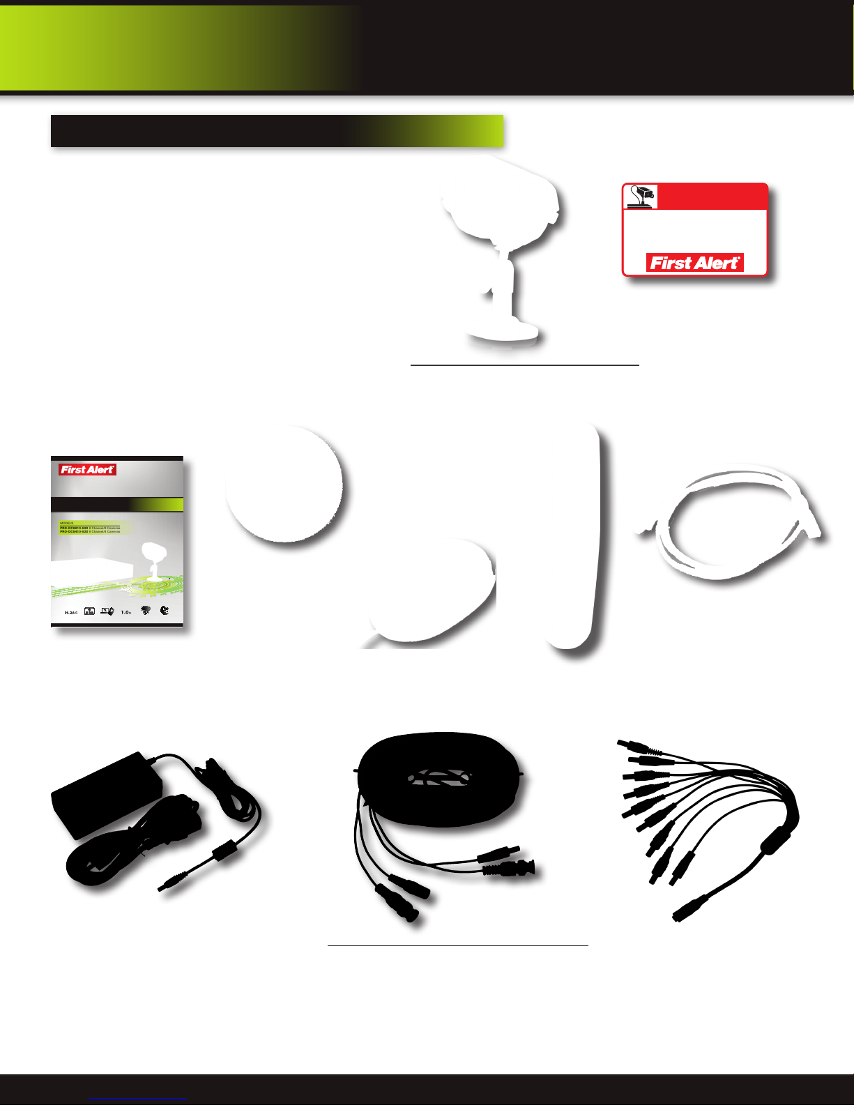
package contents
PRO-D810 H.264
8 Channel Digital DVR
with 1TB Hard Drive
BRK Series
H.264 Digital DVR
quick install guide
MODELS
PRO-DC8810-520 8 Channel/8 Cameras
PRO-DC8410-520 8 Channel/4 Cameras
H.264
COMPRESSION
VIDEO
1.0TB
DVR OPTIMIZED
INDOOR/OUTDOOR
DIGITAL DVR
MOBILE PHONE/
RECORDER
WEB READY
NIGHT
SATA HDD
520 TVL CAMERAS
VISION
Quick Install Guide
Installation Software
and Manuals
PRO-CM520 520 TVL Camera
PRO-DC8810-520: 8 Cameras
PRO-DC8410-520: 4 Cameras
USB Mouse
Remote Control
WARNING
THESE PREMISES ARE UNDER
24 HOUR VIDEO SURVEILLANCE
PROTECTED BY
2 Window
Warning Decals
RJ45 Ethernet Cable
(cable color may be
different)
Power Supply for
DVR and Cameras
60’ BNC Video & DC Power Cable
PRO-DC8810-520: 8 Cables
PRO-DC8410-520: 4 Cables
Page 7
9-way Power splitter -
8 cameras, 1 DVR
Page 8
product overview
dvr controls
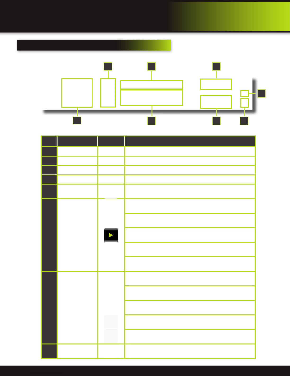
Front Panel
4 3
7
Item Function Control Description
1
Standby Press to enter standby mode
2
IR Sensor IR receiver for the remote control
3
MENU/EXIT Press to open/close the main menu
4
LED Indicators Shows status of Link, 100M, Full, Alarm, Record, HDD.
5
Channel Numbers
Press buttons 1~8 to view the selected channel in full-screen. Pressing
9 returns screen to 8 camera display mode.
6
2
5
8
1
During playback,
6
press the following:
Navigation/OK/PTZ
(Select direction
7
arrow, then press OK
to start PTZ motion)
Increase reverse playback speed 2X, 4X, 8X
Press to freeze playback to one frame, then press again to advance
frame-by-frame
Press to start playback
Press to slow playback speed by 1/2, 1/4, 1/8
Press to increase forward playback speed 2X, 4X, 8X
In menus, press to confirm selections; in PTZ mode, press to change the
navigation buttons to control the connected PTZ camera (not included)
Press to move cursor up; in PTZ mode, press to pan camera up
Press to move cursor down; in PTZ mode, press to pan camera down
Press to move cursor left; in PTZ mode, press to pan camera left
Press to move cursor right; in PTZ mode, press to pan camera right
8
USB
Connect a USB flash drive to the left port for data backup and firmware
upgrades. Connect a USB mouse to the right port
Page 8
Page 9
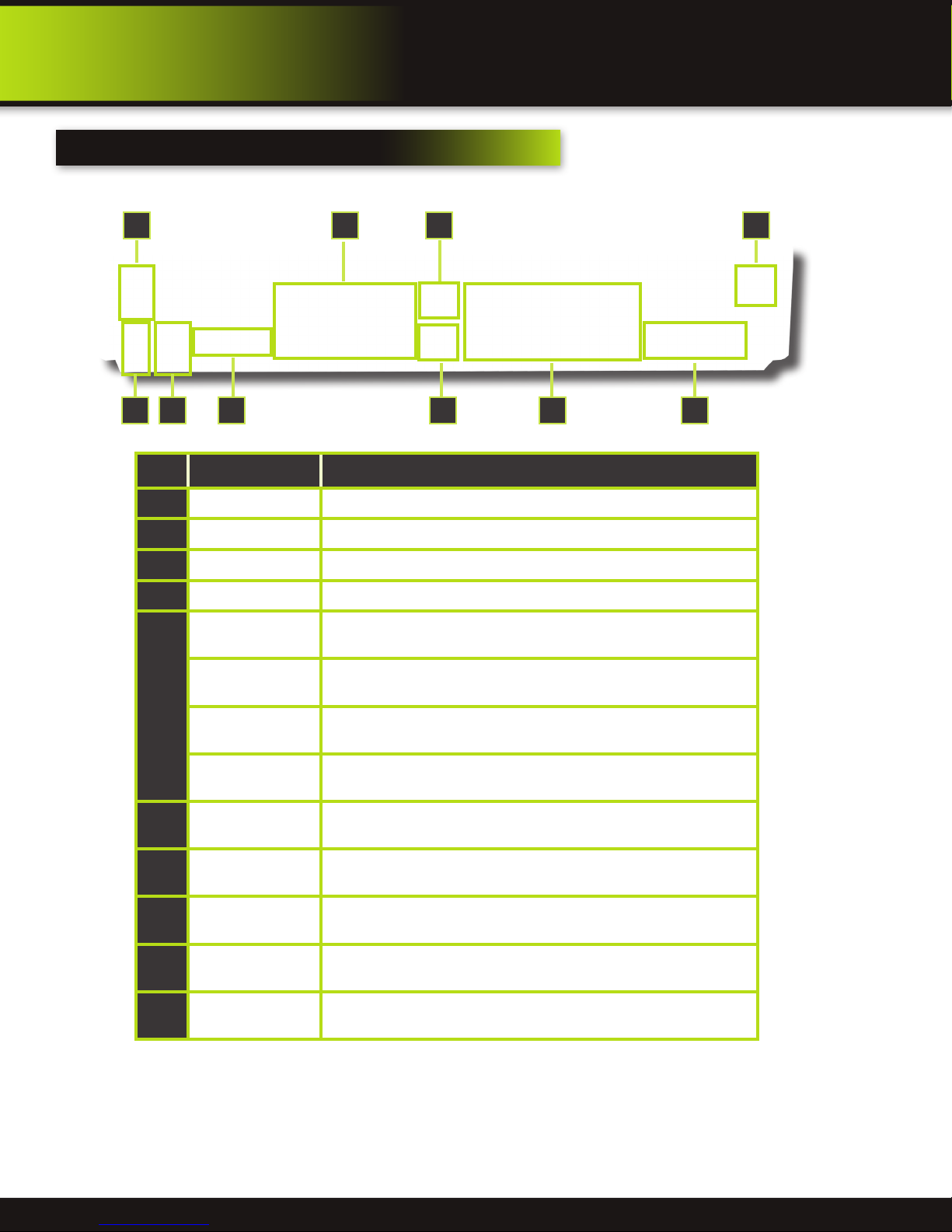
back Panel
product overview
dvr controls
9 10
21
Item Function Description
1
POWER Input DC 12V/5A power connection
2
Network For connecting RJ45 ethernet cable to PC or router
3
VGA Output For connecting to a VGA monitor
4
Video Output For connecting to a BNC monitor (800 x 600) - NTSC or PAL
Alarm Input 8 alarm inputs
76
543 8
Alarm Output Output for alarm
5
RS485 For connecting PTZ cameras
+12V
6
Audio Input
7
Audio Output For connecting audio signal to amplified speakers (RCA jacks)
8
Video Input For connecting video signal from cameras (BNC)
9
Power Switch Power On/Off
10
Ground Ground connection
Power supply for alarm block inputs, the current is 100mA (to prevent
short circuits)
For connecting audio signal from audio capable cameras or self powered
microphones (RCA jacks)
Page 9
Page 10
product overview
remote control
remote control
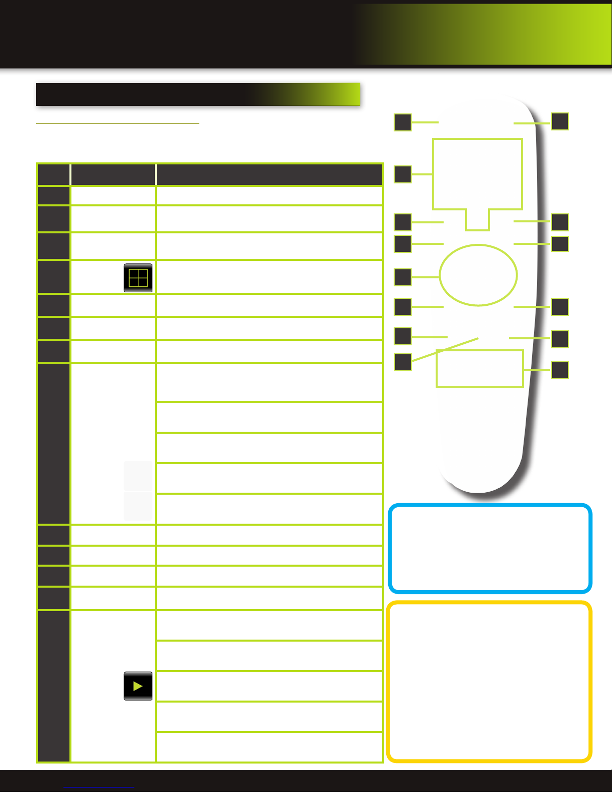
Remote Control Operation
The remote control is the secondary input device for navigating the system’s
interface. In device operation, the OK key has the same function as “left click” of
the mouse.
Item Function Description
1
STANDBY Press to turn standby mode ON/OFF
2
LOGIN/LOCK
Number/Channel
3
Buttons
Window
4
Display
5
MENU Opens the main menu
6
PTZ Press to open the PTZ control window
7
EXIT Close menu windows
Navigation/
8
OK
If “Security” has been enabled in the setup menu, press to
open the user password login screen or log off system.
While in menus, press buttons 0~9 to enter values; during
live viewing, press to view channels in full-screen
Press to switch between quad and split-screen displays
In menus, press to confirm selections; in PTZ mode, press
to change the navigation buttons to control the connected
PTZ camera (not included)
Press to move cursor up; in PTZ mode, press to pan
camera up
Press to move cursor down; in PTZ mode, press to pan
camera down
3
6
8
9
10
1
11
2
54
7
9
12
13
Press to move cursor left; in PTZ mode, press to pan
camera left
Press to move cursor right; in PTZ mode, press to pan
camera right
9
+ / - In menus, press to adjust values
10
RECORD Press to start manual recording
11
STOP Press to stop manual recording
12
EXTRA For future use
Increase reverse playback speed 2X, 4X, 8X
Press to freeze playback to one frame, then press again to
advance frame-by-frame
Playback
13
Controls
Press to start playback
Press to slow playback speed by 1/2, 1/4, 1/8
Press to increase forward playback speed 2X, 4X, 8X
Remote Control
TIP: When using the remote
control to enter password
and camera titles, select the
field using the navigation
buttons, press ENTER, and then press the
number buttons.
Battery Replacement Instructions for Use
Always purchase the correct
size and grade of battery most
suitable for intended use. Re-
place all batteries of a set at
the same time. Clean the battery contacts
and also those of the device prior to battery
installation. Ensure the batteries are installed
correctly with regard to polarity (+ and -). Remove batteries from equipment that is not to
be used for an extended period of time. Remove used batteries promptly.
Page 10
Page 11

pRODUCT oVERVIEW
MOUSE and virtual Keypad
MOUSE controls
Mouse Operation with this DVR
The mouse is the primary input device for navigating system
menus.
NOTE: Unless otherwise noted, all system functions described in
this manual are achieved through mouse input.
To use a mouse with the system:
Connect a USB mouse to the USB MOUSE port on front panel of
the system.
NOTE: Only the USB 2.0 port on the front panel is designed for
data backup to a USB flash drive. Do not connect a USB flash
drive to the USB MOUSE port.
Use the mouse buttons to perform the following:
Left-Button:
1
• Click to select a menu option
• During live viewing in split-screen double-click on a
channel to view the selected channel in full-screen
• Double-click the channel again to return to split-screen
view
• Selecting letter or number on the virtual keypad
DVR Front Face
Connect Mouse &
USB Drive
Right-Button:
2
• Click to open the Quick Access Menu
• Exits any window
• Exits any menu or re-opens previous menu
Scroll-Wheel:
3
• Forward-switch to VGA; backward-switch to BNC (CVBS)
Virtual Keypad
Virtual Keypad
To enter text or numerical data, the system uses a virtual
keypad. In fields where letters or numbers can be entered, you
can switch between various formats – numbers, upper case
(ABC) and lower case (abc). Note you can access all numbers
when in the “Letters” virtual keypads. See below.
2
3
1
Mouse Button Operation
Numbers
Letters-Uppercase
Letters-Lowercase
Page 11
Page 12
product overview
cAMERA AND pOWER cONNECTIONS
Installing cameras
Mounting Cameras and Running Cable
Select the position for the camera and secure the camera stand. Screw the
camera onto the stand. Adjust camera to the proper view angle. Make sure
the lens is upright relative to the subject. Tighten the thumb bolt. First Alert
cameras can be either ceiling or wall mounted by simply reversing the camera
stand mounting. See “Camera Orientation” Info box. Holes are provided on
both the bottom and back of the camera housing
to accommodate most mounting requirements.
Attach proper length of cable and run from
camera to DVR location. Note: Power cable ends
are different. Be sure the correct power connector
end matches “To Camera” or “To DVR”. Tip Connect cable at camera end before running
cable to verify orientation is correct. Also, see
Information box on “Longer Cable Runs”.
To DVR To Camera
Verify Cable Orientation
Camera - Wall Mounted
Camera - Ceiling Mounted
Longer Cable Runs
Longer cable runs may require an upgrade to RG59 Coax cable. First Alert kits ship
with economical AV cable that is designed to work well up to the length of cable
provided, usually around 60 feet. If longer distances between camera and DVR are
required, you will need to upgrade to RG59 Coax cable. We provide several lengths
may require fire rated cable, FT-4/CMR UL approved for in-wall installations.
up to 300 feet. In addition, if you need to run cable for in-wall installations, then you
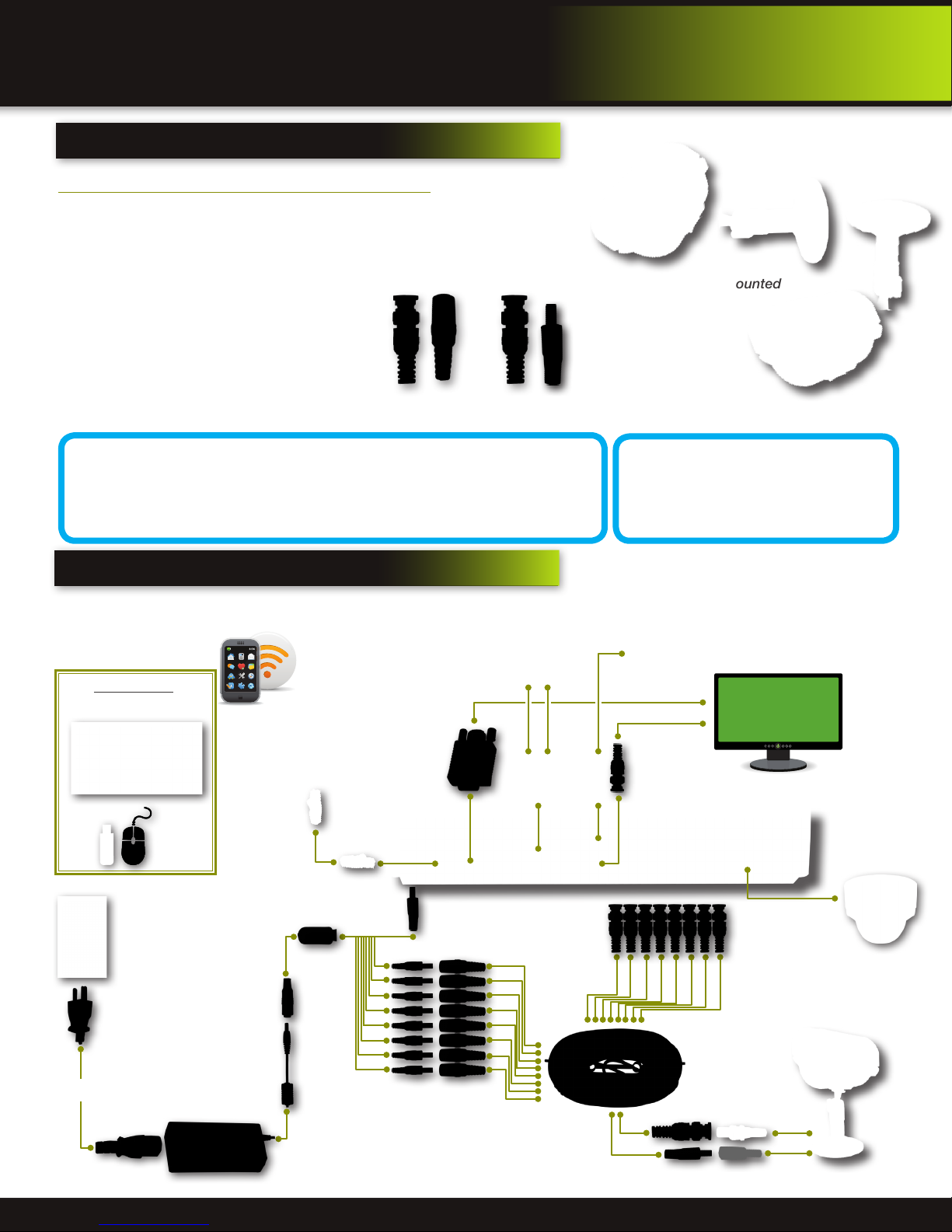
connecting devices
Follow this diagram to make device connections. Note, some devices are
not included with this kit. See “What’s in the Box” for included devices.
RCA Audio In from Audio
Cameras or Powered
Microphone
(Not included)
DVR Front Face
Connect Mouse &
USB Drive
Smartphone
through Mobile
Internet Setup
(Smartphone Not
included)
RJ45 Ethernet
to Router and
Internet
Camera Orientation
It’s important the camera is
mounted correctly to ensure the
image is not upside down as the
camera lens can only be positioned one way.
RCA Audio Out to
Powered Speakers
(Not included)
VGA to PC Monitor or TV
BNC to Security Camera Monitor
(Not included)
Splitter 8 camera/
1 Power
Power
from 120V
DC Converter - 12V
Power to DVR
Power to Cameras
Page 12
PTZ & Alarm
Connections
(Cameras not
included)
Video to DVR
Channels 1-8
AV Cable: BNC/
DC Power
(1 per Camera)
Video to Camera
Power to Camera
Page 13

system operation
system start up
Default Video Output
The default video output for the DVR system is VGA. If you connect a BNC (CVBS)
monitor on initial setup, you will need to use the mouse “Scroll Wheel” to switch to
the BNC output to be able to use the mouse. Roll the mouse “Scroll Wheel” backward to go to BNC and forward to go to VGA. The REMARK screen is shown on
startup.
Power On/Off
To power the system On/Off, connect the power
cable to the DC 12V port on the rear panel. Flip
the toggle switch on in the back of the DVR. At
startup, the system performs a basic system
check and runs an initial loading sequence. After
a few moments, the system loads a live display
view.
initial setup
Switch between VGA to BNC Output
Power Switch
Standby Mode
The system can also be put into Standby Mode. Power will remain to the system but
will not be recording. To start/stop Standby Mode:
1. Press and hold the POWER button on the front panel or remote control until the
prompt closes. The system enters standby mode. You can also enter Standby
mode through the Quick Access Menu. See next page.
2. To exit standby mode, press and hold the POWER button on the front panel or
remote control until the system beeps. The system will begin powering up.
User Login
Password
ATTENTION: By default, passwords are disabled on the system. You do not need
to enter a password when accessing any system menus. However, for security
purposes, it is highly recommended to enable passwords on the system using
the Password Menu. See “Password” section for details on setting up passwords.
Click APPLY to access the menus or click EXIT to cancel password setup and
return to the LIVE VIEW screen.
Standby Mode
User Login Menu
Page 13
Page 14

initial setup
system operation
Live View Screen
The Live View Screen is the home or main viewing screen. It shows live video of all current
cameras connected to the DVR. You can double-click a channel at any time to view it
in single-channel mode. You access all menus from this Live View screen via the Quick
Access Menu. You will also see the Channel number or name, time and day information
(see page 16 “Camera Display Setup” for customizing the Live View Screen). It is also
where you will see various information and warning icons, depending on what is happening
in the system or with the alarms that may be set.
】 means the channel is recording
【R
】 means motion detection alarm activated on the channel
【M
】 means an input on the alarm block activated on the channel
【I
】 means either the hard drive is not installed, it is bad or it is full
【H
】 means Tamper Alarm has been activated on the channel
【B
Quick Access Menu
When using the mouse, use the Quick Access Menu to access several system options, including the Main Menu. Select one of the following options:
• MAIN MENU: Opens the main system menu
• KEYLOCK: Logs current user off the system. Re-login required.
• CHN SWITCH: Select type of split-screen display
• VIDEO SEARCH: Open the Search Menu to view recorded video
• PTZ : Opens the PTZ control menu
• MUTE: Mute listen-in audio on the system. Recording of audio is still enabled.
• MANUAL REC: Start manual recording
• STOP REC: Stop manual recording
• ROTATION: Sets the time each channel is visible when rotating through chan-
nels. The Loop Time in seconds is set in the Video Setup Screen.
• START CRUISE: Click to start preset PTZ Camera motion
• STOP CRUISE: Click to stop preset PTZ Camera motion
• STANDBY: Puts system in standby mode.
Quick Access Menu
To close the Sub-Menu, left click anywhere on-screen.
Main Viewing Screen
Showing No HDD in DVR
Main Menu Access
To open the Main Menu: Right-click anywhere on-screen to open the Quick Access Menu and select MAIN MENU (mouse only), or
press the MENU button on the remote control or front panel of the system.
NOTE: If passwords are enabled on the system, you need to select your Device ID and enter the 6-digit numerical password to open
the Main Menu.
Main Menu
1. RECORD SEARCH: Search for recorded video on the system.
2. RECORD: Configure recording parameters (quality, resolution), set record
modes, and enable/disable audio recording. Note: Audio capable cameras
(not included) are required for audio recording on the system.
3. HDD: Display hard drive status and format the internal hard drive of the system.
4. BASIC: Open the Basic Setup Menu, which lets you set the system language,
date and time, device IDs and passwords, and configure display, audio and
video settings.
5. ADVANCED: Opens the Advanced Setup Menu, which lets you view system
info, configure alarm, PTZ, motion detect, maintenance, mobile, and network
settings.
6. EXIT: Closes the Main Menu.
7. Displays information about the contents of the selected Main Menu icon.
No HDD installed
NOTE: If there is no HDD installed, or the HDD is not recognized, or the HDD is not formatted in Live
View a red【H】will be displayed in the video preview interface. You must format the HDD in the DVR
before first use. See: Menu > HDD management > Format. After formatting, the system will restart.
Main Menu
Page 14
Page 15

initial setup
system operation
Password Setup
Setting Up Passwords & User Permissions
When you first startup your DVR, you are automatically logged in as the ADMIN under Device ID: 000000. By default, passwords
are disabled on the system. You will not need a password to log in or access menus. You will not need a password to access your
system using the browser-based remote software.
The system employs two levels of user authorities connected to a Device ID. The levels are as follows:
1. ADMIN (administrator): Has full control of the system, and can change both administrator and user passwords and enable/
disable password checking
2. USER (normal user): Only has access to live viewing, search, playback, and other limited authorities.
For security reasons, it is highly recommended to enable passwords on your system. If you enable passwords, you must select an 1-8 digit ADMIN password and a
1-8 digit USER password. The ADMIN and USER passwords must not be the same.
If you forget your password, contact First Alert Consumer Affairs for help in resetting. For your security you will be required to verify proof of ownership by providing
a notarized letter. See BRK website for the “Notarized Statement Of Ownership
For Security System Override Pass Codes” form to be completed.
To customize PASSWORD settings, click BASIC from the Main Menu, then click
PASSWORD. You are now in the User Setup menu. From here you can change the
DEVICE ID. Note this is not a required for a basic setup:
1. Device ID: Click the field beside Device ID and enter a 6-digit numerical Device
ID using the Virtual Keyboard.
Next, in the USER SETUP Menu click CONFIG to set up users. NOTE: Only the Administrator can enter the CONFIG setup. You can change the
• STATE: active or not (Note for User Set #1, ADMIN, the STATE of ACTIVE or
INACTIVE cannot be changed.)
• USER NAME: Assign or change user name using the virtual keyboard.
• PASSWORD ENABLE: enable or disable the password for this user
• PASSWORD: Password must be 1-8 digits
• CONFIRM: confirm the password
• PERMISSION: Select all permissions for this user. (NOTE: this option is not
available for ADMIN as they have all permissions). Available choices are:
Record Setup, HDD Manage, Language Setup, Time Setup, Start/Stop Record,
Display Setup, Alarm Setup, System Info, Motion Detect, Mobile Setup, System
Setup, PTZ Setup, Network Setup, Video/Audio Set, IE Preview for each of 8
Channels, Playback for each of 8
Channels.
Navigate the PERMISSION
Screens by:
• NEXT: Moves to next selecting
page.
• ALL: Selects all permissions.
• CLEAN: Clears all permissions.
NOTE: This page is working
for administrator. Administrator can assign permissions for
user. User just can see but can
not change their permissions.
User Setup
User Password Setup
Multi User Login
After Users are set up, Select active user from USER NAME drop down box to log on with previously set up permissions. The active user(s) will be available. Next, key in the device ID and
user password.
User Login-Multi Users
User Permission Screen 1
Page 15
User Permission Screen 2
Page 16

initial setup
system operation
camera display setup
Setting Up Cameras for Viewing and Recording
Use the Display Setup menu to customize channel titles, show/hide the date and time in live viewing and playback, and enable/
disable preview channels. To customize Display settings, click BASIC from the Main Menu, then click DISPLAY:
Display
1. Configure the following options:
• NAME: Click any of the fields and enter a new title for the selected
channel using the Virtual Keyboard (mouse only)
• POSITION: Reposition the channel title; select TOPLEFT, BOTTOMLEFT, TOPRIGHT, BOTTOMRIGHT, or OFF. If OFF, the title will not be
displayed for the selected channel
• COLOR: Adjust CHROMATICITY, LUMINOSITY, CONTRAST, and SATURATION for the selected channel
• LIVE: This feature can be very useful if your display monitor is in public
view. With LIVE in the OFF selection that channel will appear black on
the display to give the impression that no cameras are connected and
the system is not recording. Select ON/OFF to enable or disable this
feature
• PREVIEW TIME: Select ON/OFF to show/ hide the date and time during
live viewing
• RECORD TIME: Select ON/OFF to show/hide the date and time during
playback.
2. Scroll down to change the settings for the remaining channels
3. Click APPLY to save your settings. Click OK in the REMARK window. Click
EXIT.
Display Setup Menu
Video/Audio
Use the Video/Audio menu to set the resolution and camera setup
on the system. To configure Video/Audio options:
1. Under VGA RESOLUTION, select 800 x 600, 1024 x 768, 1280 x 1024,
1366 x 768, 1440 x 900.
2. Under CAMERA SYSTEM, select NTSC or PAL. (See info box below)
3. Under LOOP TIME (SECOND), enter with virtual keypad from 1 to 300. Sets
the time each channel is visible when rotating through channels.
4. Under VOLUME SETUP, adjust slider from 0 to 63. Click X to save.
5. Under MARGIN, adjust TOP, BOTTOM, LEFT, RIGHT margin with slider from
0 -10. Also adjust Display from VGA or CVBS. Default is VGA and 0 for all
margins
6. Click APPLY. Click OK in the REMARK window.
7. Click EXIT in all menus until all windows are closed.
Audio/Video Recording
Caution: Audio surveillance in some
states is illegal or requires permission from one or both parties to record
someone’s voice. Laws are also different from residential vs. commercial applications.
Some federal, state, and local laws prohibit certain
surveillance activities and/or the use or distribution of
the information obtained from such activities. Prior
to using this system, you should become familiar with
the pertinent laws to ensure compliance with those
applicable to surveillance activities.
up of 525 individual scan lines.
PAL (Phase Alternating Line) is the predominant video system or
standard mostly used overseas. In PAL, 25 frames are transmitted
each second. Each frame is made up of 625 individual scan lines.
NTSC or PAL?
NTSC (National Television Standards Committee)
is the video system or standard used in North America and most of South America. In NTSC, 30 frames
are transmitted each second. Each frame is made
Color Set-up
Video/Audio Menu
Page 16
Page 17

language, date and time
Setting Up Language/Date/Time
Set the system language, date and time, passwords, and configure audio and
display options. The Basic Setup Menu contains the following sub-menus: Language, Date/Time, Password, Display, and Video/Audio.
Language
To change the system language:, from the drop-down menu select LANGUAGE.
Click APPLY. Click OK in the confirmation window. Click EXIT to close the
menu.
NOTE: The system will restart when you finish system language setup. The
default is English.
Mountain: -7
Western: -8
Alaska/Hawaii: -9 through -11
System Language Menu
Date/Time
It is highly recommended to immediately set the date and time when first setting
up your system. To set the date and time:
1. Click DATE/TIME and configure the following options:
• DATE: Enter the day, month, and year.
• DATE FORMAT: Select DD/MM/YYYY, MM/DD/YYYY, or YYYY/MM/DD
• TIME: Enter the time
• TIME FORMAT: Use the drop-down menu and select 12HOURS or
24HOURS. If 12HOURS is selected, then set AM or PM.
• DST: Use the drop-down menu to select ON/OFF to enable/disable Daylight Savings Time. See below for details on setting DST.
2. Click ZONE to enter your time zone from -12 to +12. To find your time zone
visit www.worldtimezone.com or other similar sites.
See Info box for US codes.
3. Click SAVE DATE AND TIME. The new date and time are saved. Click EXIT.
initial setup
system operation
Basic Setup Menu
US World Time Zones - UTC Codes
UTC stands for Universal Time Coordinates
or Greenwich Mean Time (GMT)
Eastern: -5
Central: -6
System Time/Date Setup
Daylight Savings Time (DST)
To set daylight savings time:
1. Under DST, select ON. DST options appear.
2. Under DST MODE select one of the following:
• DEFAULT: The Default setting will apply the United States daylight savings time period from the second Sunday of
March to the first Sunday in November (go to step 3)
• CUSTOM: Set customized start and end times for DST (go to step 4)
3. If using the DEFAULT, click APPLY. Click EXIT.
4. If setting a CUSTOM DST, use the drop-down menus to select a week and month for the start and end times.
5. Click APPLY. Click OK in the confirmation window.
6. Click EXIT in each menu until all windows are closed.
Why Set a Date & Time?
It’s important to set the proper date and time before continuing so that you can easily locate recorded events.
Inaccurate dates and times on files may affect their admissibility as evidence in court. In addition, when
changing current time settings, to avoid possible confusion with the time stamps on recorded and currently
recording files, stop all ongoing recording processes before altering the system time and restart recording
using the new settings.
Page 17
Page 18
Basic Operation
Recording
Basic Setup
Use the BASIC SETUP menu to configure language, date and time settings,
password setup, along with display, video and audio settings. You can also exit
the system through this menu. The Basic Setup menu contains the following
sub-menus: Language, Date/Time, Password, Display, Video/Audio and Exit.
recording
RECORD Mode
Configure Recording Options:
In this Menu you have three recording options: POWER UP (Continuous), TIMER
RECORD (enables SCHEDULE menu) and ALARM (within SCHEDULE menu). By
default, the DVR is set to record continuously. Set parameters as follows:
1. From the Main Menu click RECORD. Under SWITCH, use the drop-down menus
and select ON/OFF to enable/disable recording from the selected channel. Note:
If SWITCH is set to OFF, then Motion Detect, Alarm and Manual Record are also
disabled for that channel.
2. Under RESOLUTION, select CIF, HD1, or D1.
NOTE: NTSC: @30fps, PAL: @25fps. Recording capabilities for both NTSC & PAL:
Channels 1 & 2: D1, HD1, CIF; Channels 3-8: HD1, CIF.
3. BITRATE (Kbps): See table for details.
4. FRAMERATE: Choose the recording frame rate 1-30, (fps – frames per second).
The lower the value, the less life-like and more jerky the recorded movements
will be. However, a lower frame rate uses less HDD space. Make your choice
depending on the precision with which you want to follow the events being
recorded. Frame-rate of each channel can be adjusted but is limited by the total
resources available. The total frame rate for all channels combined cannot exceed
420 (NTSC) fps. Note: Although the chipset is NTSC 480, part of the resources are
used for other internal functions and cannot be allocated to recording resources.
The ratios of D1, HD1 and CIF are as follows: 1 D1= 4 x CIF, 1 HD1 = 2 x CIF.
5. AUDIO, select ENABLE or DISABLE. If audio recording is enabled, the system will
record audio from connected audio capable cameras (not included). See caution statement on audio recording in Video/Audio section.
6. REC. MODE, select POWER UP or TIMER RECORD. If you select POWER UP, the
system will record continuously when the system is powered on. If you select TIMER
RECORD, you have to set a recording schedule on the system.
7. REC. SIZE (Record Size), select 15MIN, 30MIN, 45MIN, or 60MIN.
NOTE: Record Size sets the file size for recorded video files on the system. Instead of recording data as one large file, the system
will divide the data into blocks of 15, 30, 45, or 60 minutes. This makes the recorded data easier to search
8. MASK FIELD lets you block a specific portion of a channel you do not want recorded or shown on the display screen. This can be
useful if you need to conceal a sensitive area being captured by the camera. See next section for details.
9. Click APPLY. Click OK in the REMARK window. Click EXIT.
Recording Schedule (TIMER RECORD)
You can program the DVR to record according to a customized recording schedule.
The Schedule Grid shows the days of the week and hour blocks 00~23. You can set
Alarm Recording (Red), General Recording (Green), or No Recording (Blue) to each
time block of each day. To set a recording schedule:
1. Open the Main Menu and click RECORD.
2. Under REC. MODE, select TIMER RECORD.
3. Click SCHEDULE. The Schedule menu opens.
4. Under CHANNEL, select specific channels or select ALL.
5. Below the grid, click either ALARM (red), GENERAL (Green), or NO RECORD
(Blue) and then click a time block on the desired day.
6. Use the FROM/TO drop-down menus to copy the schedule of one day to
another. For example, if you want your schedule for Monday to be the same on
Wednesday: under FROM select MON, under TO select WED, and then click COPY.
7. Click APPLY. Click OK in the REMARK window. Click EXIT.
Basic Setup Menu
Record Menu
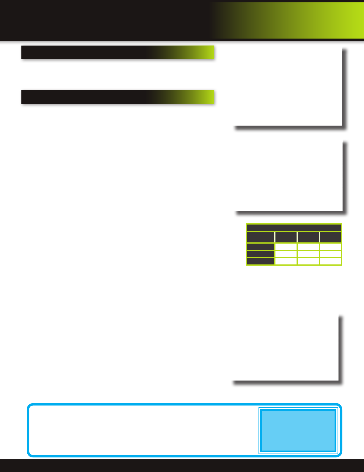
Bitrate in Kbps
Image
Quality
CIF
HD1
D1
Recording Schedule
Low Medium High
384 512 768
512 768 1024
896 1024 1280
CCTV Resolution
CCTV resolution is measured in vertical and horizontal pixel dimensions and typically
limited by the capabilities of both the camera and the recorder that you are using for
your CCTV surveillance installation. CCTV systems use an analog video signal. For
television specifications (which CCTV uses) the highest resolution that can be captured
and stored is 704 x 480 (NTSC for the United States) and 720 x 576 (PAL for Europe). This resolution
is known as D1 resolution. A high end CCTV recorder is capable of recording at up to D1 resolution.
CCTV Resolutions
D1: 704 x 480
HD1 (2CIF): 704 x 240
CIF: 352 x 240
QCIF: 176 x 120
Page 18
Page 19

Recording Schedule (TIMER RECORD) Example
You want your system to record continuously on all channels from 9 AM to 5 PM Monday to
Friday. You also want Alarm/Motion recording from 5 PM to 9 AM. You do not want the
system to record Saturday or Sunday:
1. Open the Schedule menu.
2. Under CHANNEL, select ALL.
3. Click the blue NO RECORD block below the grid. A checkmark will appear
in the block.
4. Under SUN, click blocks 00~23. The
blocks will turn blue.
5. Under FROM, select SUN. Under TO
select SAT, and then click COPY.
6. Click the red ALARM block below the
grid.
7. Under MON, click blocks 00~08 and
blocks 17~23. The blocks will turn red.
8. Under FROM, select MON. Under TO
select TUE, and then click COPY. Repeat
for Wednesday, Thursday, and Friday. Your completed schedule should the same as
the schedule to the right.
9. Click APPLY. Click OK in the REMARK window. Click EXIT in all menus until all windows
are closed.
Basic Operation
Recording
Recording Schedule
Privacy Mask Field
MASK FIELD lets you block a specific portion of a channel you do not want
recorded or shown on the display screen. This can be useful if you need to
conceal a sensitive area being captured by the camera. To use the Privacy Mask
Field:
1. From the Record menu, click MASK FIELD. The Mask Field menu opens.
2. Choose a channel you wish to apply the Mask Field.
3. Select ON from the SWITCH drop-down menu.
4. Click SETUP. The Mask menu will be replaced by the full-screen camera view
of the desired channel. Using the mouse, click and drag the cursor over the
area you want to conceal. A single click will produce a small black square.
5. Right-click anywhere on the screen to return to the Mask Field menu.
6. Click APPLY. Click OK in the REMARK window. Click EXIT.
Motion Detect Setup
You can configure motion detection for each channel (Camera) connected to the
DVR. To configure motion detection:
1. From the Main Menu click ADVANCED. Then click MD (Motion Detect).
2. Under STATUS, select ON to enable motion detection for the desired channel. Scroll down for additional channels. Note: If in the RECORD screen a
Channel is set to OFF, MOTION is also disabled for that Channel.
3. Under SENSITIVITY, select 1 through 8. The higher the number, the more
sensitive the motion detection.
4. Under MD AREA SETUP, click SETUP. The red motion grid appears over the
selected channel in full screen.
5. Click the blocks in the grid to enable/disable motion detection. Red=motion
detection enabled; Clear=motion detection disabled.
6. Right-click anywhere on the screen to return to the Motion Detection menu.
7. Click EMAIL, then select ON/OFF to turn on e-mail notification. E-mail must
be configured. See manual for details.
8. Click BUZZER to turn audible notification of motion ON/OFF.
9. Click APPLY. Click OK in the confirmation window.
10. Click EXIT in all menus until all windows are closed.
NOTE: You can disable the MD buzzer in the Alarm Setup menu.
When MD is triggered, in the Live View Screen you will see a red【M】in the
Channel with a MD warning. You may also see a【R】if you set up the channel
to record when an alarm is triggered.
Motion Detect Menu
Motion Detect Grid
Page 19
Page 20

Basic Operation
Playback
playback
PLAYBACK Mode
Playback and Record Search
View recorded video on the system through the RECORD SEARCH Menu. To begin playback:
1. There are two ways to access the RECORD SEARCH menu. Right-click anywhere on the screen and select VIDEO SEARCH
from the Quick Access Menu. The RECORD SEARCH Menu opens. Or from the Main Menu select RECORD SEARCH.
NOTE: When you first open the RECORD SEARCH Menu, it displays the current month and date.
2. Click PLAY to playback the last minute of recorded video (Quick Search) OR
Under CHN select a specific channel or select ALL.
3. Under DATE, enter a date using the Virtual Keyboard (mouse only).
4. Click SEARCH. Recorded events on the system appear in red (alarm events—
includes both alarm and motion events) and green (normal recording).
5. Click a date in the Month Grid to search for video files.
6. Click a time block in the Hour Grid to view the video. Playback begins.
7. Move the mouse slightly to display the on-screen play back controls. You can
also use the playback control with buttons on the remote control or front
panel of the system.
On-screen Playback
Controls
To use the on-screen playback controls:
1. Click the VCR-like controls to play, pause, fast forward, rewind, and
slow down playback.
2. Drag the slider to adjust the volume (audio capable camera required,
not included). Select the box to mute the audio.
3. Click X to quit playback and return to the Search menu.
On-screen Playback Controls
9. Under RECORD STATE, the system shows recorded events in a Month
Grid and a Time Grid. The selected day of the month will be outlined in
red. Green=normal recording; Red=alarm recording (includes both alarm
and motion events). Click a date in the month grid to view recorded video files for that selected date in the hour grid.
File List
Use the FILE LIST sub-menu to see a detailed list of all the recorded video on your
system. To open the FILE LIST:
1. From the RECORD SEARCH Menu, click SEARCH to search the system for
recorded video.
2. Click FILE LIST at the bottom of the menu. The FILE LIST menu opens.
Record State
Record/Search Menu
Month Grid
Hour Grid
To use the File List:
1. Under TYPE, select NORMAL to view only normal recordings, ALARM, to
view alarm recordings (includes alarm and motion detection), or ALL to view
all video on your system.
2. Use the buttons on the side panel to navigate the file list:
• FIRST: Jump to the first page of the list
• PRE: Turn to the previous page
• NEXT: Turn to the next page
• LAST: Jump to the last page of the list
• ALL: Select all files
• OTHER: Toggles selections between checked and unchecked.
• BACKUP: After selecting a file(s), click to begin copying the data to a USB flash drive (not included);
3. Click any file to begin playback.
File List Menu
Page 20
Page 21

Basic Operation
Backup
Use the FILE LIST sub-menu to find recorded video on your system and copy it to
a USB flash drive (not included).
NOTE: The system is compatible with most major brands of USB flash drives, with
capacities from 256 MB to 4 GB.
To backup recorded data:
1. Connect a blank USB flash drive to the top USB port on the front panel of
the system.
2. Open the FILE LIST menu and search for recorded data on the system as
shown above.
3. Select the file you want to backup and click the “BACKUP” box next to the
file name. Select multiple files if desired. Click ALL to select all files; click
OTHER to deselect all files. NOTE: The size of each file is shown in the File
List menu. Use this to help you find a USB flash drive large enough to hold
all the files you wish to backup.
4. Click BACKUP from the side-panel to immediately begin copying the files
to the USB flash drive. NOTE: Backup progress appears in the status window. DO NOT remove the USB flash drive during backup.
5. When the space in backup device is less than recording file, the system will
prompt “Space not enough”...
6. You can remove USB device directly when backup is finished
Playback
Backup Menu & Warning Notice
USB Backup
Warning!. Do not remove the
USB drive during backup.
HDD Management
Hard Drive and USB Options:
The HDD button displays essential information about the system`s internal hard
drive, and lets you format the internal HDD and external USB flash drive (not
included). If there is no hard drive in DVR, or the DVR cannot read the hard drive,
or the hard drive is not formatted, it will display a red “H” in the video preview
interface. To access this menu, from the MAIN MENU click HDD.
The HDD menu displays the following:
1. HDD STATUS: The system will display “OK” for normal operation
2. SIZE: The size (in gigabytes) of the internal hard disk drive. The size of
your system`s internal hard drive will vary by model
3. FREE SPACE: The space (in gigabytes) remaining on the system`s internal
HDD
4. AVAILABLE TIME: The recording time (in hours) remaining on the HDD
based on your current record settings
5. OVERWRITE: Select ENABLE or DISABLE. If Overwrite is enabled, the
system will record over the oldest video data once the HDD is full. If
Overwrite is disabled, the system will stop recording once the HDD
is full and the “FULL” LED on the front panel of the system will light up.
Backup Successful Notice
HDD Management
Formatting the Internal Hard Drive
If you installed a new hard drive, you must format the hard
drive in the DVR before it can be used. Clicking on the HDD
FORMAT button will begin the formatting process. After formatting, the system will restart. ATTENTION: Formatting the
internal HDD erases all video data. This step cannot be Undone.
Hard Drive Format Warning
Page 21
Page 22

ADVANCED Operation
ALARM
Hard Drive and USB Options continued:
Formatting the USB Flash Drive
Use a USB flash drive to backup recorded video and upgrade the system`s firmware. You should always format the USB flash
drive you intend to use with the system.
NOTE: Not formatting the USB flash drive may result in improper functionality.
USB Flash Drives
The system is compatible with most major brands of USB flash drives, with capacities from 256 MB to 4 GB. If
you need to reformat your flash drive then click on the U DISK FORMAT button while the USB drive is connected
to the USB port on the front of the DVR. Be aware that this button is not for use with any external USB hard drive
you may connect to the DVR for backup. External hard drives will need to be formatted using the FAT32 format
and this can be done by connecting the drive to the USB port on a PC and reformatting it from there.
Advanced Setup
Use the ADVANCED SETUP menu to configure alarm settings, motion detection,
mobile surveillance, PTZ settings and network settings. The Advanced Setup
menu contains the following sub-menus: Alarm, Info, MD (Motion Detect),
Mobile, System, PTZ, and Network
Alarm
Alarm and E-mail Options:
Use the Alarm menu to configure alarm and e-mail settings. NOTE: External alarm
devices must be connected to the alarm block on the rear panel of the DVR in order
to use the I/O (input/ output) alarms of the system. See next section “Alarm Inputs”
and “Alarm Inputs Diagram” for details on attaching alarm inputs. To access this
menu, from the MAIN MENU click ALARM.
To configure alarm settings:
1. Under I/O CHANNEL, select NO (Normal Open), NC (Normal Closed), or OFF
for Alarm input. Alarm Input 1 on Alarm Block controls
CH1 1 (Camera 1). Scroll down to view additional channels. Note: If in the
RECORD screen a Channel is set to OFF, ALARM is also disabled for that
Channel.
2. To activate Loss Alarms use drop down menu and select ON/OFF:
• HDD LOSS: The alarm will sound if the internal HDD is damaged
• HDD SPACE: The alarm will sound when the HDD is full (overwrite must be disabled)
• VIDEO LOSS: The alarm will sound when a camera is disconnected
3. Under ALARM MANAGE, configure the following:
• OUTPUT: Set the output time (in seconds) on the spot monitor from 0s,
10s, 20s, 40s, or 60s.
• BUZZER: Set the time (in seconds) for the DVR buzzer to sound when
an alarm is triggered—0s, 10s, 20s, 40s, or 60s NOTE: Set the buzzer
to 0s if you want to disable the alarm during motion detection.
• POST REC: Set the time (in seconds) for the system to record after a
triggered alarm—30s, 1MIN, 2MIN, 5MIN
Advanced Setup Menu
Alarm Setup Menu
Alarm Manage Screen
Page 22
Page 23
Advanced Operation
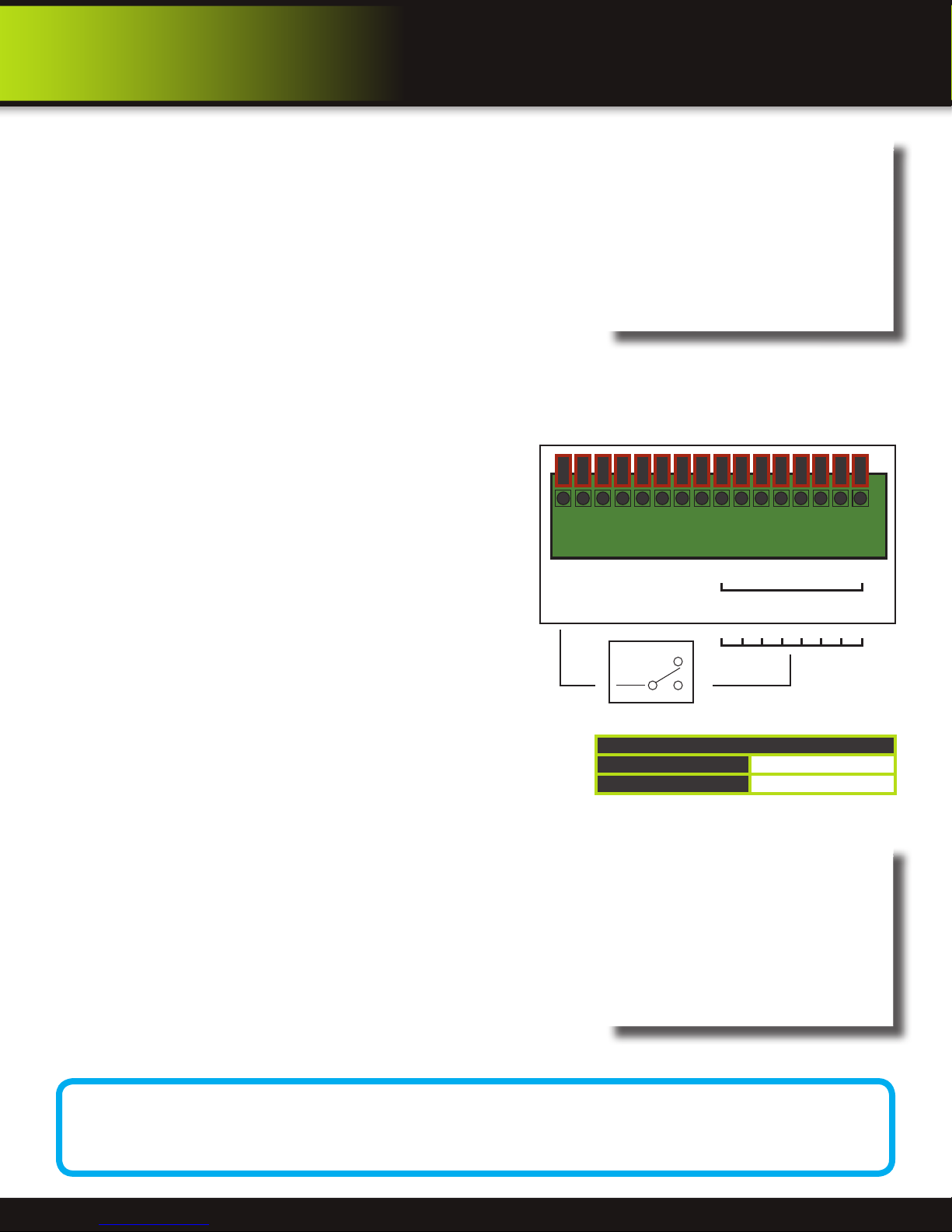
From NO or NC depending on setup
selected to alarm inputs 1 through 8
COM
NO
NC
Example Device:
Door Sensor
Use +12V from
Alarm Block
GND
+ 12V
485B
485A
GND
GND
NO
COM
1
7
6
5
4
3
2
8
ALM IN
Alarm Inputs Conguration
(for devices without voltage)
4. Use TAMPER ALARM to set the system to notify you when a camera has
been blocked by something. When a Tamper Alarm is triggered, in the Live
View Screen you will see a red【B】in the Channel with an alarm warning.
Configure the following for each channel:
• SWITCH: Turn feature ON/OFF
• SENSITIVITY: Configure LOW/MEDIUM/HIGH
5. Click APPLY. Click OK in the confirmation window.
Alarm Inputs:
Alarm inputs are devices or switches that activate when a door, window,
cabinet etc. is opened or accessed. For example, you might want to only have
the camera record when someone opens a tool cabinet or when a door opens
vs. recording when motion occurs around those areas. There may be people
moving by those areas frequently but you are only concerned about when those
areas are accessed. This saves hard drive space and makes it easier to find an
event that was recorded to the hard drive.
To configure alarm inputs for devices without their own voltage you
will use the +12V input supplied on the alarm block. See Alarm Inputs
Configuration diagram at the right.
Note: If Alarm Input Device has its own power supply make sure:
1. Voltage rating is between 6V and 12V. Do not use the +12V
connection on the Alarm Block.
2. Ground must be connected to GND in Alarm Block for device to
operate properly
When an alarm is triggered, in the Live View Screen you will see a
red【I】in the Channel with an alarm input warning. You may also see
a【R】if you set up the channel to record when an alarm is triggered.
ALarm
Tamper Alarm Setup
Alarm Ouput:
Alarm output is used to activate an external device such as a horn or
light after an alarm is triggered. To do this the DVR uses a dry contact
normally open relay. To configure alarm outputs, connect the external
device to the NO (Normally Open) and COM (Common) connections
on the alarm block as required by the device. See table for Alarm
Block Voltage. The maximum contact rating is 3A 24VDC.
Max Switching Voltage
Max Switching Current
E-mail Setup:
The system can send an e-mail notification with a JPEG snapshot for triggered events on the system. Please consult your e-mail
provider for information to enter in this screen. To setup e-mail notification:
1. Under EMAIL, select ON.
2. Under SSL, select OFF. NOTE: SSL deals with encryption. Only advanced
users should enable this option.
3. Under SMTP PORT, enter the SMTP port of your e-mail server.
4. Under SMTP, enter the SMTP address of your e-mail server. For example,
smtp.gmail.com
5. Under SEND EMAIL, enter the sender e-mail address.
6. Under SEND PW, enter the password of your e-mail server.
7. Under RECV EMAIL, enter the e-mail address that will receive the e-mail
notification.
8. Click APPLY. Click OK in the confirmation window.
9. Click EXIT in all menus until all windows are closed.
Alarm Block Voltage
up to 24VDC
up to 3A
E-mail Setup Screen
E-mail Tip
Depending upon your settings, the system can generate a lot of e-mail alerts. For that reason, we recommend
setting up a dedicated e-mail address specifically for the Security System alert notices. Also to better manage
your alerts, you will want the alert e-mails to go to a different account than the one sending them.
Page 23
Page 24

Advanced Operation
System
System Info and System Update
System Information:
View system information, including the firmware version, MAC address, and
serial number of the system. To access this menu, from the MAIN MENU click
ADVANCED then click INFO.
System Maintain
Use the SYSTEM MAINTAIN menu to update system firmware and set an
automatic system reset schedule. To access this menu, from the MAIN MENU click
ADVANCED then click MAINTAIN.
To enable AUTO MAINTAIN:
1. Under AUTO RESET, select ON. The Settings option appears.
2. Under SETTINGS, select EVERY DAY, EVERY WEEK, or EVERY MONTH. The
date drop-down menu appears.
3. Select the date for auto-reset from the drop-down menu.
4. Enter the time for auto-reset using the Virtual Keyboard (mouse only).
5. Click APPLY. Click OK in the confirmation window
System Maintain
System Info
To restore factory settings:
1. Click DEFAULT SETTINGS. This brings you to the DEFAULT SELECTION
screen.
• Options available to reset are: Display Setup, Record Setup, Record
Schedule, Network Setup, DDNS Setup, HDD Management, Alarm
Setup, E-Mail Setup, PTZ Setup, Mobile Setup, Motion Detection, Color
Setup, Time Setup, Password Setup, Alarm Manage, System Maintain
• ALL: Selects all settings.
• CLEAN: Clears all settings.
• LOAD DEFAULT: Restores all settings to factory defaults
2. Click OK in the prompt. This will restore all or selected items to the original
factory settings. NOTE: Recorded video on the HDD will not be erased.
To restart the DVR (soft-reset):
1. Click RESTART.
2. Click OK in the prompt. The system will perform a soft-reset and load to a live
split-screen view.
To upgrade firmware (Download file “FIRMWARE: How to Install
Upgrade” from www.brkelectronics.com for details):
1. Copy the firmware file to an empty USB flash drive. The firmware file should
not be in a folder.
2. Connect the USB flash drive to the top USB port on the front panel of your
system.
3. Open the SYSTEM MAINTAIN (MAIN MENU>ADVANCED>MAINTAIN).
4. Click SYSTEM UPDATE. The system will scan the USB flash drive and begin
updating the firmware. Do not remove the USB flash drive while the upgrade
is taking place.
5. PARAMETER EXPORT: Copies the system settings of the device to an empty
USB flash drive.
6. PARAMETER IMPORT: Imports
system settings from another device.
Restore Factory Defaults
Warning! Restoring factory defaults will cause any settings you’ve
made to the system to be deleted. This includes recording and
network setups along with passwords. This step cannot be undone. NOTE: Recorded video on the HDD will not be erased.
Default Page Selection
System Update Warning Message
Page 24
Page 25
Advanced Operation
Pan tilt zoom...PTZ
Pan/Tilt/Zoom (PTZ) Setup:
NOTE: Consult the instruction manual of your PTZ camera for complete
information about your camera, including protocol, baud rate and parity
settings before beginning setup. Enter these settings in the DVR.
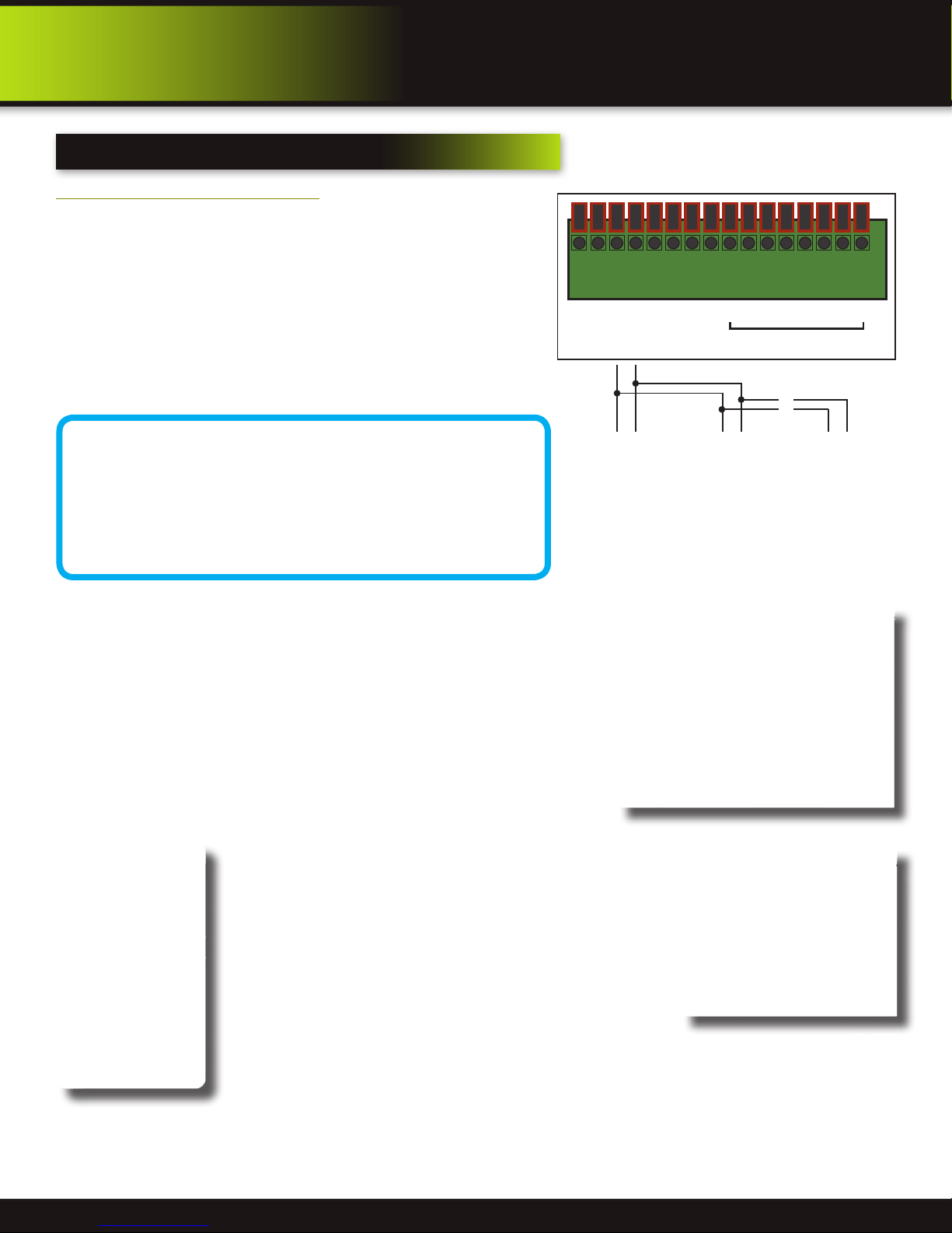
Step 1: Connect your PTZ Camera to this DVR
Connect a PTZ camera to the BNC and DC power cables. Also, connect
the communication cable from the PTZ camera to the 485A (TX, +)
and 485B (RX, -) control inputs to the Alarm/PTZ block on the back
of the DVR. Note there is only one set of PTZ control inputs (485A &
485B), however multiple PTZ cameras can be set up by making parallel
connections. See diagram for details and see “PTZ Camera Setup” Info
box for additional information.
PTZ Camera Setup
NOTE: It is recommended for best results to use 120Ω
shielded twisted pair cable of a sufficient gauge to meet
your application length. 18 to 22 gauge is usually sufficient.
In addition, be sure to only install the 120Ω terminating
resistor that comes with your PTZ camera in the last parallel connected
camera. Keeping that resistor in all cameras can possibly degrade the
signal and can cause unexpected or loss of operation and control.
PTZ Inputs Conguration
GND
+ 12V
485B
485A
GND
AB AB AB
NO
COM
GND
1
3
2
ALM IN
~
~
4
PTZ
6
5
7
8
Install 120 Ω
terminating
resistor in last
camera only
Step 2: Configure PTZ Communication Settings:
To access this menu, from the MAIN MENU click ADVANCED then PTZ (see
PTZ Setup image). Use the slider bar on the right of the screen to access all 8
channels available on this DVR. The PTZ setting options for each camera can be
selected independently and are available next to each camera’s channel number.
1. Under PROTOCOL, select PELCO-D or PELCO-P for the selected channel.
2. Under BAUD RATE, select 1200, 2400, 4800, or 9600.
3. Under VERIFY, select ODD, EVEN, MARK, SPACE, or NONE parity bits. Note:
Mark = 1, Space = 0 parity bits.
4. Under ADDRESS, provide an address from 001~255 using the Virtual Keyboard for each PTZ camera.
5. Click APPLY. Click OK in the confirmation window.
6. Click EXIT in all menus until all windows are closed.
Step 3: Configure the Operation & Control of your PTZ
Camera(s):
After your PTZ camera(s) are set up you can control their
operation from your DVR. Note: Individual features must be
available on your camera to operate.
1. In Live View, double click on the Channel with the connected
PTZ Camera to open to full screen view. This selects the
channel to configure and control.
2. From the Quick Access Menu select PTZ. (See image at left)
3. From the PTZ Setup screen you can adjust:
• Pan Speed: Adjusts the speed the camera will move.
• Zoom: “+” Zooms in and “-” zooms out
• Focus: “+” and “-” focuses the picture.
• Iris: “+” lets more light in and “-” removes light from the picture. This is useful to correct
backlight issues.
Select PTZ from the
Quick Access Menu
• Directional keys: Left and Right Arrows control the pan; Up and Down arrows control the tilt. Tip:
Hold the mouse button down while clicking on an Arrow Key and drag the cursor away from the
key to initiate the Auto Movement feature. The camera will pan continuously 360 degrees from
the position it is in or tilt up or down to the limit of the camera until you click OK. This is useful if
you want to manually operate the camera without continuously holding or clicking the arrows.
PTZ Setup
PTZ Setup - Sub Menu
Page 25
Page 26

Advanced Operation
PTZ Setup
Pan/Tilt/Zoom (PTZ) Setup Continued:
In the PTZ Senior Control screen you can set or control the following for each PRESET defined:
1. SET PRESET: Saves any PRESET functions changed with this screen.
2. CLEAN PRESET: Clears a defined PRESET without going to the SET CRUISE screen.
3. CALL PRESET: Calls a defined PRESET without going to the SET CRUISE screen.
4. AUTO SCAN: Enables AUTO SCAN feature without going through Quick Access Menu.
5. STOP SCAN: Enables AUTO SCAN feature without going through Quick Access Menu.
6. SET CRUISE: Configures the Cruise Setting. See next step for details.
PTZ Setup - Sub Menu
Step 4: Configure the CRUISE SETTING of your PTZ Camera.
This feature allows you to set up a series of Pan, Tilt and Hold camera sequences and then
execute those operations in a continuous loop. This is useful when you want to record or
view the same set of pre-determined areas. You can customize these settings for each PTZ
camera connected to your DVR.
Understanding the CRUISE SETTING Options:
To access this menu In Live View, double click on the Channel with the connected PTZ
Camera to open to full screen view. From the Quick Access Menu select PTZ. Click SETUP
from the PTZ SETUP screen and you will see the PTZ SENIOR CONTROL Menu. Click SET
CRUISE to configure the cruise settings for your PTZ Camera.
1. TOTAL: The total number of PRESET’s defined
2. PRESET: A defined pan, tilt and hold sequence. You can enter up to 128 PRESET’s for a
channel depending on how many areas you want to view or record.
3. STOP TIME: The total time in seconds for the camera to move through its defined
operation. Note: This includes travel time from the previous set point completion plus the length of time you want the camera
to hold on a position. For example, if the STOP TIME is set to 10 seconds and the travel time from the previous set point is
6 seconds, then the camera will hold on the position for only 4 seconds. It can take some trial and error to get the timing you
want. To help fine tune your timing after a set point is defined, selecting CALL will travel through the complete cruise setting
for the PRESET allowing you to adjust your timing.
4. SET: Stores the PRESET in memory
5. CLEAR: Removes the defined pan, tilt and hold sequence for a CRUISE SETUP. PRESETS will still be unchanged.
6. APPLY: Saves all PRESETS defined.
How to define a Cruise Setting PRESET
1. With your PTZ Channel selected and the CRUISE SETTING menu open as explained in the previous sections, be sure TOTAL
is 0 and you are on PRESET 001. If not click CLEAR to reset the PRESET’s.
2. Using the Arrow Keys adjust the camera to the first position you want to monitor.
3. Set the STOP TIME setting using the Virtual Keypad. (See STOP TIME explanation above for important information)
4. Click SET to save. The TOTAL and PRESET numbers move to the next number.
5. Repeat steps 2 through 4 for each PRESET you want to define.
6. Click APPLY to save all PRESETS for this CRUISE SETTING.
7. Follow the same steps above to configure other PTZ cameras on other Channels.
8. Click EXIT several times to get to the Live View screen
9. Use the Quick Access Menu to select START CRUISE and STOP CRUISE to begin or end Cruise operation for all defined PTZ
channels.
PTZ Senior Control
PTZ Cruise Setting
Page 26
Page 27
REMOTE Access
Network Setup
Network Setup for Remote Access
Use the NETWORK SETUP menu to configure your network and DNS settings for remote access. If you are only going to access
the DVR locally from a computer attached to the same router as the DVR, you only
need to configure settings using either the DHCP or STATIC IP. Because you are on
the same network, port forwarding and knowing the public IP address are not
necessary. You will just access the DVR by entering the IP address of the DVR from
the NETWORK setup into the Internet Explorer browser window. If you are going to
take advantage of the Remote Surveillance feature, such as for a smart phone or to
view your system outside of your network over the internet you will need to review
and set up Port Forwarding and the DDNS. After you setup the NETWORK settings
using DHCP , STATIC IP or DDNS, see the REMOTE SURVEILLANCE section for
further instructions.
There are five options for configuring the DVR to be accessed remotely: DHCP,
Static IP, UPnP, PPPOE, and DDNS. To access this menu, from the MAIN MENU
click ADVANCED then NETWORK SETUP. Be sure your router or network is connected to the LAN port on the back of the DVR.
DHCP (Dynamic Host Configuration Protocol)
DHCP is a protocol used by networked devices (clients) to obtain various parameters necessary for the clients to operate in an
Internet Protocol (IP) network. It allows you to quickly connect to your network and obtain an IP address from the router. After
the initial setup, we recommend that you disable DHCP, then select STATIC from the TYPE drop down box and set the IP address
between 1~100. For example, if your IP address is 192.168.0.107, change the last digits to 90 (i.e. 192.163.0.90). This ensures that
port forwarding will not change in the event of power failure or resetting of your network.
To configure DHCP settings:
1. Select DHCP from the TYPE drop down box in the NETWORK SETUP Menu. You should see the message “Getting IP...”
The router will assign an IP address. This is the IP address you will forward port 80 to on the router so you can access the
DVR from remote computers See comment above to configure a static IP.
2. Click APPLY. Click OK in the confirmation window.
3. If necessary, change the Media and Web Port settings
Network Setup
Static IP
You will need to setup the network settings on the DVR to match the settings of the router to which your DVR is connected. This
information can be obtained through your computer. Windows 7, Vista or XP all have similar ways to access this data.
To get the router settings:
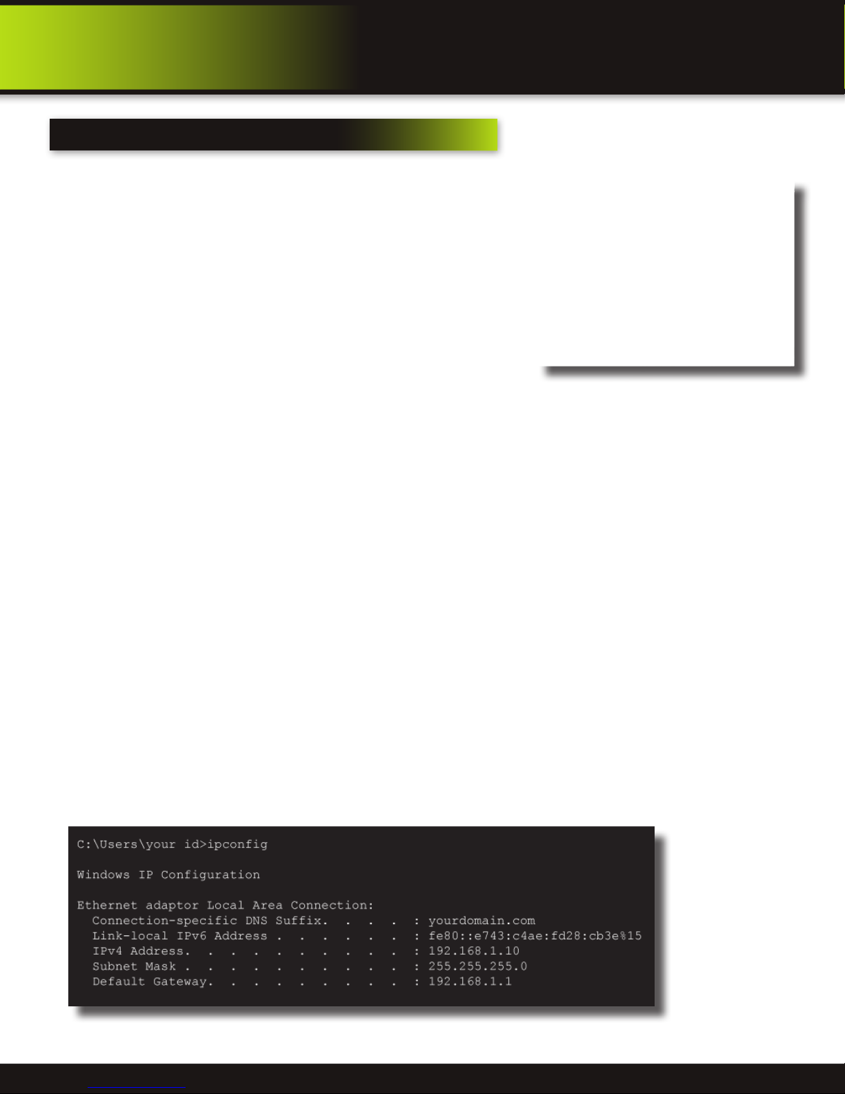
1. To access the router’s settings you will need to enter the Command (CMD) panel on your computer. It must be connected
to the same router as your DVR.
• In Windows 7 or Vista, from the “START” menu type “CMD” in the field that says, “Search programs and files” and hit
ENTER or click on the magnifying glass icon.
• In Windows XP select “Run” from the “START” menu. Type “CMD” after the prompt
2. Type “ipconfig” at the prompt and hit enter
3. You will get a screen that contains information similar to what is shown below. Within all of the information shown,
locate the IPv4, Subnet Mask and Gateway addresses. These you will enter into the STATIC IP screen in the NETWORK
SETTINGS menu in your DVR. See next step.
Windows “ipconfig” Info Example
Page 27
Page 28

REMOTE Access
Network Setup
To configure Static IP settings in the DVR:
1. Select STATIC IP from the TYPE drop down box in the NETWORK SETUP
Menu.
2. Enter your IP Address, Subnet mask, and Gateway info you obtained from
your computer through the previous step in the respective fields using the
Virtual Keyboard.
3. Click APPLY. Click OK in the confirmation window.
4. If necessary, change the Media and Web Port settings
UPnP (Universal Plug and Play)
UPnP Forum is an industry initiative designed to enable simple and robust
connectivity among consumer electronics, intelligent appliances and mobile
devices from many different vendors. This protocol is designed to allow networked
devices, such as computers, printers, mobile devices to automatically discover
each other’s presence on a network and to connect seamlessly for data sharing
and communications. NOTE: Your Router must support UPnP function to use this protocol.
To configure UPnP settings:
1. Enable the UPnP function in your Router.
2. In this DVR, Open the MAIN MENU and click ADVANCE.
3. From the Advanced Setup menu, click NETWORK.
4. Under UPnP, select ON.
5. Click APPLY to save your settings and then click OK in the confirmation window.
6. Using a remote PC, open Internet Explorer.
7. In the address bar, enter your Router WAN IP address immediately followed by WEB PORT (no spaces). Example: http://
XXX.XXX.XXX.XXX(Router WAN IP):XXX(WEB PORT)
8. Enter your system ADMIN password and select INTERNET. NOTE: If you have not enabled passwords on the system, leave
the password field blank.
9. Click LOGIN.
Static IP Menu
PPPoE (Point-to-Point Protocol over Ethernet)
The Point-to-Point Protocol over Ethernet (PPPoE) is a network protocol for
encapsulating Point-to-Point Protocol (PPP) frames inside Ethernet frames. It is
used mainly with DSL services where individual users connect to the DSL modem
over Ethernet and in plain Metro Ethernet networks. Use this option if you are going
to attach the DVR directly to a DSL or Cable modem instead of a router.
To configure PPPoE settings:
1. Select PPPOE from the TYPE drop down box in the NETWORK SETUP
Menu.
2. You will need to contact your ISP provider for the user name and password
need to enter into the PPPOE NAME and PASSWORD fields.
3. Click APPLY. Click OK in the confirmation window.
4. If necessary, change the Media and Web Port settings.
PPPoE Setup
Page 28
Page 29

Remote Access
Network Setup
DDNS (Dynamic Domain Name Service)
A DDNS account allows you to set up a web site address that points back to your Local Network so you can access the DVR over
the Internet using a static or dynamic IP address. One problem with a dynamic address is your internet service provider (ISP)
changes this address from time to time. When it changes you need to re-configure your DVR with the new address. To do so you
will have to get the new IP address. Although you can go to www.myipaddress.com to get the new IP address, you still have to
make the changes manually.
So what are your choices? The first would be to obtain a
static IP address from your ISP. This can get expensive due
to setup fees and monthly rates. Fortunately there is an
easier option. That is to use a dynamic domain name service
(DDNS) to get a domain name that can be linked to your
dynamic IP address. While there are multiple DDNS services
available, we recommend www.dyndns.com as the DVR has
been already configured to accept account information from
this service.
How DynDNS.com works:
1. You install the DynDNS® Updater software on your
network
2. When your Internet Service Provider changes the your
IP address, the DynDNS Updater detects that the
network’s IP address has changed
3. The DynDNS Updater sends the new IP address to
DynDNS.com
4. The DynDNS.com update server receives the
information, and assigns the new IP address to your
Dynamic DNS hostname you created.
In addition to automatically keeping up with the changes in
the address, you will now be able to enter a domain name
rather than a string of digits when accessing the DVR in
Internet Explorer.
DynDNS.com Setup Screen
How to obtain your Domain Name from www.dyndns.com
1. Using a computer that is connected to the same router as the DVR, use Internet Explorer to go to www.dyndns.com
2. Decide whether you only need one domain name or require multiple names.
3. Follow the instructions for completing the required information to register
4. You will receive a confirmation e-mail with your new domain name. An example domain name might be
[email protected]. You will need it to configure the DVR.
First obtain your Router DNS
You need to get your DNS manually from your router. You will
need the Primary or Secondary DNS from your router for DDNS to
function properly.
To obtain your Primary or Secondary DNS:
1. In your web browser, log in to your router using its Default
Gateway address. NOTE: Refer to your router`s manual or
software for login information. You can also get the Default
Gateway on your PC by selecting Start>Run. Type CMD and
press Enter. In the Command Prompt window type ipconfig and
press Enter.
2. View its WAN settings. Write down the Primary or Secondary
DNS address for use in the next step.
WAN Settings Example
Page 29
Page 30
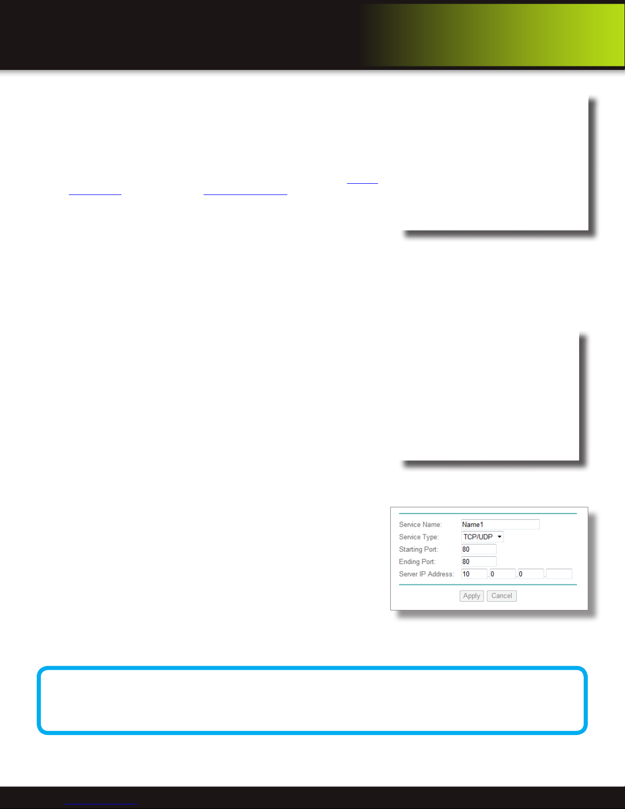
REMOTE Access
Network Setup
Next configure DDNS settings in the DVR
From the Network Setup menu, enter Primary or Secondary DNS from the WAN
settings of your router in the DNS field
1. Click DDNS SETTINGS.
2. Under DDNS, select ON.
3. Under SERVICE, select DYNDNS if you obtained your domain name from
DynDNS.com.
4. Under DOMAIN NAME, enter your DDNS domain name you received
from the confirmation email. For example, if your domain name is adam@
dyndns.com, you need to enter [email protected], in the text field using
the Virtual Keyboard.
5. Enter your DDNS user name and password in the respective fields.
6. Click APPLY. Click OK in the confirmation window.
7. Click EXIT. The system will prompt you that it must restart. Click OK.
Port Forwarding
Port Forwarding allows computers and devices outside of your network to communicate with the DVR. You will need to forward
ports 80, 100 and 9000 from the attached router to the IP address of the DVR. Gather the make, model and IP address of the
router. If you changed the default router login, then you will need to know the user name and password for that router. Follow
these steps:
Step 1: How to Determine the IP Address of the DVR
NOTE! The DVR and PC must be connected to the same router and both must be
powered up before proceeding.
1. Select DHCP from the TYPE drop down box in the NETWORK SETUP
Menu. You should see the message “Getting IP...” The router will assign an
IP address.
2. Restart the DVR.
3. Once the DVR has restarted, reopen the Network Setup window and the
IP address of the DVR will now be listed. This is the address to which
you will forward ports 80 and 9000. If you plan to access your DVR via a
smartphone, you will need to forward port 100 as well. Be sure to configure
the Mobile Network screen of this DVR with port 100. See Mobile Phone
Setup in this manual for details.
DDNS Setup
Step 2: Configure your Router for Port Forwarding
NOTE: Although all routers are different, the following is the basic information
that needs to be configured. Consult your Router Manual for details on Port
Forwarding configuration for your specific router. Some Internet Service
Providers (ISP) may block access to these settings in the router they provide.
You may need to contact your ISP to make these changes for you.
1. Access your routers’s Port Forwarding screen (See image at right). Your’s
may be slightly different but the information required is the same.
2. Enter your port forwarding information for each port you want to forward.
As noted above you will need to forward ports 80, 100 and 9000.
• Assign a name
• Start Port: 80; End Port: 80
• Enter your DVR IP address you obtained from “Step 1: How to
Determine the IP Address of the DVR”
• Click Apply and repeat for the remaining ports.
Port Forwarding Naming Tip
For clarity and easier identification of ports in your router we suggest naming the ports as follows: Port 80 is for
your Web Browser - name this port “DVR-Web”. Port 9000 is for streaming media - name this port “DVR-Media”.
Port 100 is for your mobile phone - name this port “DVR-Mobile”.
Network Setup-Getting IP Address
Port Forwarding Screen from Router
Page 30
Page 31

REMOTE Access
Remote Surveillance
Remote Surveillance
Remote Surveillance using Internet Explorer 8 or 9:
The DVR features built-in browser-based software that allows you to access your system remotely over your local area network
(LAN) or over the Internet using Internet Explorer®. Once you have configured the network settings on the DVR to match those on
your router and forwarded the ports needed by the DVR to enable remote access over the Internet, you will be ready to remotely
view your cameras using a webcam program based on an ActiveX control. For this to work, you will have to enable the ActiveX
control options that are built into Internet Explorer. You will also need to check your “User Account Control” setting.
Note: To use Internet Explorer 9 you must enable “Display all websites in Compatibility View”
before you connect to the DVR.
IE9 Compatibility
View Setting Screen
Configuring Windows “User Account Control”:
Check the “User Account Control” setting in Windows Vista or Windows 7 to be sure the setting is configured as shown below. If
not you might receive an error message informing of a codec that is missing or not installed.
Windows Vista
1. Open the Control Panel
2. Select “User Accounts and Family Safety”
3. Select “Add or Remove User Account”
4. Select user account to change
5. Select Turn User Account Control on or off”. Note: Depending on your version of Vista, this screen might be accessible
on the bottom of the “Select User Account to Change” screen under “Additional things you can do” > “Go to main user
account page”.
6. Uncheck the box next to “Use User Account Control (UAC) to help protect your computer.”
7. You will need to re-start your computer for the change to take effect.
Windows 7
1. Open the Control Panel
2. Select “User Accounts”
3. Select “Change User Account Control Settings”
4. In the “Choose to be notified about changes to your computer” screen, move the slider to the lowest setting “Never notify”.
Page 31
Page 32

REMOTE Access
Remote Surveillance
Configuring ActiveX Control in Internet Explorer 8:
1. Open Internet Explorer 8
2. Click on Tools
3. Select Internet Options in the pull-down menu
4. Click on the Security Tab
5. Select Trusted Sites
6. Click on the Sites button
7. Uncheck the “Require server verification (https:) for all sites in this zone”
button.
8. Type the DVR’s IP address (obtained during Network Setup) or DDNS domain
name (obtained through DynDNS.com setup) into the “Add this website to the
zone:” box.
9. Click the Add button
10. Close the window.
11. Back in the “Security Tab” screen,
click the “Custom level…”button.
12. Pull down the “Reset to:” menu
button and select “Low”
13. Click the “Reset...” button
14. Click “Yes” when asked, “Are you
sure you want to change the setting
for this zone?”
15. Click OK
16. Click Apply
17. Click OK
18. Close Internet Explorer. You are
now ready to access the DVR using
Internet Explorer 8.
Trusted Sites
Internet Options-Security Screen
Using Remote Surveillance:
With your system connected, you can now log in to your DVR using Internet Explorer.
The software from the DVR will install the first time you access the DVR through Internet Explorer and will allow you to operate the network remotely. The DVR supports
access over LAN and WAN, also supports IP and domain name access.
Logging Into Your System Remotely
With your IP address, you can now log in to your DVR system either locally or
remotely.
1. Open Internet Explorer. To view locally: In the address bar enter the IP address
that your router automatically gave your DVR (see Port Forwarding section)
or your static IP address given to you by your Internet Service Provider or IT
administrator. To view remotely: In the address bar enter your IP address for
your computer (not the DVR IP address). This is either your IP address received
via “ipconfig” as described in Network Setup - “To get the router settings” or
your IP address as described in DDNS setup or by going to www.whatismyIP.
com. Note: For business applications, firewalls may restrict or mask the true
IP address of your computer. You may need to contact your IT administrator to
obtain this information.
2. You must install the ActiveX® in order to access your system. Click the attention bar at the top of the main page and select Install ActiveX Control. DVR Net viewer will reset.
3. In the warning box click Install. The login page appears. Leave the password field blank (default). NOTE: If you have
enabled passwords on your system, enter your USER or ADMIN password. However, only the ADMIN can change settings
and options on the system.
4. Select LAN or INTERNET from the drop-down menu and click LOGIN.
Security Settings
Remote Surveillance-Login Screen
Setup Required Prior to Remote Access
NOTE: Your system must be connected to your LAN or WAN, Windows and Internet Explorer must be configured
as described in the previous sections Configuring Windows “User Account Control” and Configuring Active X
Control in Internet Explorer and the DVR settings must have been setup properly as described in the Network
Setup for Remote Access section before attempting remote access.
Page 32
Page 33
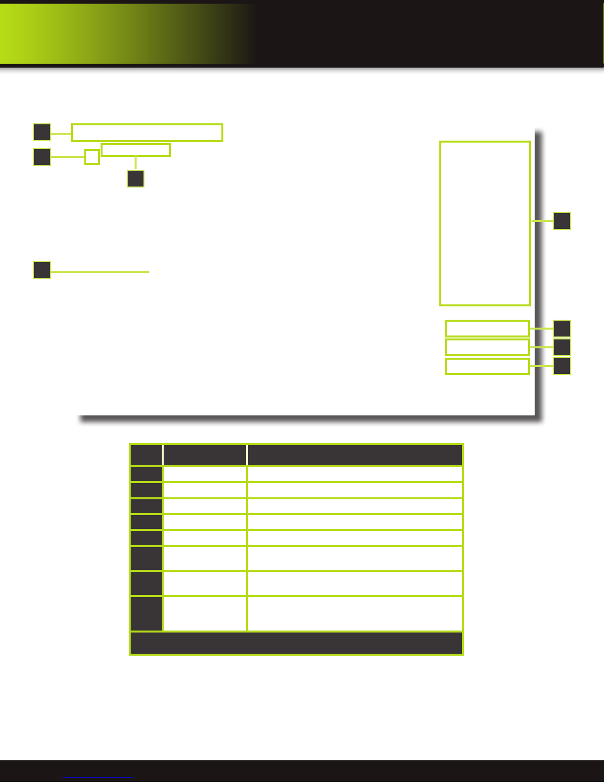
Remote Surveillance
Remote Surveillance Main Screen:
Upon login, the Remote Surveillance main screen appears in your browser.
1
4
3
2
REMOTE Access
5
Item Function Description
Modes Click LIVE, PLAYBACK, and SETUP
1
Main Screen Main display screen for live viewing and playback
2
Time Stamp Time stamp appears on each channel
3
Channel Channel number appears in the top left corner
4
PTZ Control PTZ control for any connected PTZ cameras (not included).
5
6
7
8
Functions
Display Modes
Volume/Mute
Click the icons to show/hide channels, take screen captures,
and record
Click the icons to view channels in single-channel full-screen,
quad, and split-screen configurations
Select a channel (outlined in red) and then click the bars to
increase/decrease volume; click the icon to mute/ unmute
volume.*
6
7
8
*Note: Audio capable cameras (not included) are required for audio recording on the system.
Page 33
Page 34

REMOTE Access
Remote Surveillance
Live Viewing Tab:
By default, Remote Surveillance opens in Live Viewing mode (split-screen).
To use Live Viewing:
1. Click LIVE at the top of the main screen.
2. Click the display mode icons to view the main screen in single-channel, quad, or split-screen configurations. You can also
double-click a channel at any time to view it in single-channel.
3. Click to show or hide all the channel windows.
4. Click to start/stop manual recording to your PC on ALL channels. For more details see RECORDING.
5. Select a channel (outlined in red) and then click the audio bars to increase or decrease listen-in volume. Click the icon to
mute/unmute.
Live Viewing Talk Function
NOTE: The Talk function is not supported.
Recording
You can record video directly to your PC using the remote surveillance software.
To record video to your PC, from Live viewing, click to start/stop manual recording to your PC on ALL channels
Quick Access Menu
Right-click any channel to open the sub-menu.
The sub-menu contains the following options:
Remote Viewing-
Quick Access Menu
PTZ Control
You must have a PTZ camera (not included) connected to the system in order to use the PTZ controls.
To control a PTZ camera:
1. Select the channel of the connected PTZ camera(s).
2. Click the navigation arrows to pan and tilt the camera.
3. Click + /- to control zoom, focus, and iris.
4. Enter presets.
5. Click SETTING, HAND, and CLEAR to further control presets.
Recording
NOTE: You will record video to your PC
regardless of the recording mode on the
system itself. By default, recorded files are
saved in C:\DVR\[ip_address]\Record.
Screen Captures
Use the remote surveillance software to take a snapshot of the channels on the main display screen.
Screen Captures can be useful for your own records, or may be needed by authorities in case of a
security incident.
To take a screen capture:
1. From Live Viewing, select the channel you want to capture. The selected channel will be highlighted in a red frame.
2. Click .
3. Click OK in the confirmation window. Screen captures are saved as BMP files to the default save location (C:\DVR\...).
Remote Viewing -
PTZ Control
Page 34
Page 35

REMOTE Access
Remote Surveillance
Playback Tab
Use the Replay menu to search and playback recorded video on your system.
Remote Viewing-Playback Screen
To use the replay menu:
1. Click REPLAY at the top of the main screen. The main screen will be grey.
2. Click REFRESH below the calendar to view the recorded files for the current month. NOTE: Normal recording is indicated
by a clock icon; alarm recording (alarm, loss, and motion events) are indicated by an exclamation mark icon.
3. Double-click a file from the File List to playback the file in the main screen. The icon in the file list changes to “ ”.Control
playback using the buttons at the bottom of the main screen.
Remote Viewing-Progress Bar
The purple bar indicates the download progress. The green marker indicates playback progress. You can click and drag the
playback marker (will turn from green to orange) to advance or rewind playback as needed. Click Play, Pause, Stop, Fast
Forward, Slow and Next Frame to perform those functions.
Page 35
Page 36

REMOTE Access
Remote Surveillance
Search
Use the calendar and drop-down menus to search for recorded video on your system.
1. Click < > to change the month on the calendar. Dates with recorded video data will
appear in bold.
2. Click the date. Recorded video files will populate the File List.
3. From the Channel drop-down menu, select a specific channel or select ALL
CHANNEL and then click SEARCH.
4. From the Type drop-down menu, select COMMON (normal recording), ALARM, or
ALL TYPE and then click SEARCH.
5. Double-click the file from the File List to playback the file in the main screen.
Remote Backup
You can backup recorded video files from your system to your PC using the Replay
menu in the remote surveillance software.
To backup files remotely:
1. Click PLAYBACK at the top of the main screen.
2. Double-click a file from the File List to begin playback.
3. Click BACKUP. Backup begins to C:/DVR/[ip_address]/Backup NOTE: If you
playback a file, you must wait for the file to load before backing it up otherwise you
may receive an error message
Remote Viewing-Error Message
4. When file backup is complete, click OK in the confirmation
window. The confirmation window show the save path of
the backup file. NOTE: Backup files are saved as .264 files.
Player Software
NOTE: Use the Player Software included on
the software CD to playback backed up video.
Remote Viewing-Search Calendar
Remote Viewing-File backup Location
Remote Viewing-Playback Software
Page 36
Page 37

REMOTE Access
Remote Surveillance
Setup Tab
Use the SETUP tab to configure the settings of your system from a remote location. NOTE: If the Main Menu is open on the
system, you will not be able to make changes to the system from the remote location.
To open remote setup:
Click SETUP at the top of the main screen. The Remote Setup menu features the following tabbed options:
• RECORD
• ALARM
• PTZ
• NETWORK
• SETTING
• MAINTENANCE
• HOST INFO
RECORD
You can check and change the parameter settings as
configured in the DVR.
Remote Setup - Record Screen
PTZ
You can check and change the parameter settings as
configured in the DVR.
ALARM
You can check and change the parameter settings as
configured in the DVR.
Remote Setup - Alarm Screen
NETWORK
You can check and change the parameter settings as
configured in the DVR.
Remote Setup - PTZ Screen
Remote Setup - Network Screen
Page 37
Page 38

REMOTE Access
Remote Surveillance
SETTING
You can check and change the parameter settings as
configured in the DVR
1. BANDWIDTH: Set the bandwidth in kbps (128k, 192k,
256k, 384k, 512k, 1024k) that you want to allocate for
traffic based on internet bandwidth available. This
bandwidth does not include audio.
2. FILE SAVE PATH: The path where you want to save
captured picture and recording video.
MAINTENANCE
You can check and change the parameter settings as
configured in the DVR along with rebooting the system and
upgrading firmware.
1. TELECONTROL: Remote reboot DVR or format HDD.
2. REMOTE UPGRADE: Remote upgrade DVR firmware.
Remote Setup - Setting Screen
HOST INFO
This interface allows you to view system information such
as HDD status, remain record time, firmware version and
MAC Address. All the information is for viewing only and
cannot be changed remotely.
Remote Setup - Host Info Screen
Remote Setup - Maintenance Screen
Page 38
Page 39

Mobile Phone
Setup and Control
Mobile Phone
Mobile Setup
Mobile Setup allows you to send alerts to your cellular phone running Windows
Mobile Pro, Android, Blackberry, or iPhone on 3G networks. To get the latest
software it is recommended that from your phone you go to your App Store or
Market icon and search for the MEye application.
Step1: Configure DVR - For all phones configure MOBILE settings as follows:
1. From the MAIN Menu click ADVANCED then MOBILE.
2. Under MOBILE NETWORK, select 3G, 2.75G, or 2.5G. NOTE: Contact your
cellular provider if you are unsure about the network of your cellular phone.
3. Under MOBILE PORT, enter your mobile port number. Note: this should be
port 100 you forwarded from your router.
4. Click APPLY. Click OK in the confirmation window.
5. Click EXIT in all menus until all windows are closed.
Step 2: Configure Your Phone
1. From your phone go to your App Store or Market. Search for the MEye application.
2. Download and Install the App.
3. Go to the settings screen. (See below for examples of iPhone, Android, Windows and
Blackberry phones. Your screens may vary.)
• Enter a name
• Enter your IP address for your computer (not the DVR IP address). You can easily get your
IP address as described in Network Setup - Static IP or by going to www.whatismyIP.
com. Note: For business applications, firewalls may restrict or mask the true IP address of
your computer. You may need to contact your IT administrator to obtain this information.
• Enter 100 in the Port box.
• Click OK or Back to save the information.
Mobile Setup
MEye Application
Icon
iPhone Settings Screen
Android Settings Screen Windows Phone-
Mobile Access
NOTE! Before you can use Mobile Access you need to setup
the network configuration on the DVR and forward port 100 as
described in the “Port Forwarding” section of this manual.
Blackberry Phone - Settings Screen
Settings Screen
Page 39
Page 40

Mobile Access
Remote Surveillance
Mobile Setup-continued
4. Go to the Main Screen and start the session by selecting the Play button. Select a Channel number to view each connected
camera. Depending on your setup and phone you can control PTZ cameras and other functions. See your application for
available features. Below are screen shots from various phones.
iPhone Main Screen
Windows Phone PTZ Screen
Android Main Screen
Windows Phone Main Screen
Blackberry Phone - Main Screen
Page 40
Page 41
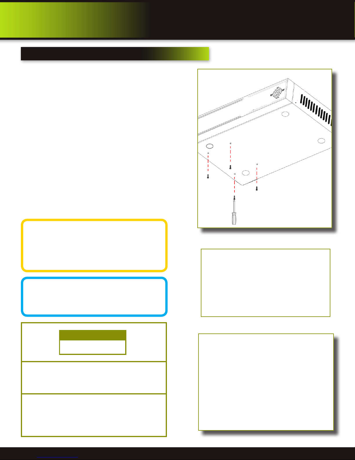
Hard Drive Removal and Installation
HDD Installation
To replace the hard drive in the DVR:
1. CAUTION: TO REDUCE THE RISK OF ELECTRIC SHOCK.
UNPLUG ALL POWER SOURCES, INCLUDING CAMERAS FROM
THE DVR BEFORE REMOVING COVER. FAILURE TO DO SO
CAN RESULT IN DAMAGE TO THE DVR OR ITS COMPONENTS
AS WELL AS INJURY OR DEATH
1. Remove screws securing the cover of the DVR and remove
cover
2. Disconnect the hard drive power and data cables
3. Remove the screws securing the hard drive to the chassis.
4. Remove old hard drive and replace with the new one.
5. Re-install the screws securing the hard drive to the chassis.
6. Re-connect the hard drive power and data cables.
7. Replace the cover and screws. Note: Format hard drive per
instructions in HDD MANAGEMENT section.
Appendix
Hard Drive
Caution!
When working with electrostatic sensitive
devices such as hard disk or DVR
unit, make sure you use a static-free
workstation. Any electrostatic energy
coming in contact with the hard disk or DVR can damage
it permanently.
Hard Drive Format
NOTE: A new hard drive must be formatted
after installation. Format per instructions
in the HDD MANAGEMENT section of this
manual.
CAUTION!
RISK OF ELECTRIC SHOCK
CAUTION: TO REDUCE THE RISK OF ELECTRIC SHOCK.
UNPLUG ALL POWER SOURCES, INCLUDING CAMERAS FROM
THE DVR BEFORE REMOVING COVER. FAILURE TO DO SO CAN
RESULT IN DAMAGE TO THE DVR OR ITS COMPONENTS AS
WELL AS INJURY OR DEATH.
The lightning ash with arrowhead symbol, within an equilateral
triangle, is intended to alert the user to the presence of un-insulated
“dangerous voltage” within the product’s enclosure that may be of
sufcient magnitude to constitute a risk of electric shock.
The exclamation point within an equilateral triangle, is intended to
alert the user to the presence of important operating and maintenance
(servicing) instructions in the literature accompanying the appliance.
Hard Drive Remove/Install Screws from Below
Hard Drive - Remove/Connect Cables
Hard Drive - Connected to Circuit Board
Page 41
Page 42

Appendix
Specifications
Technical Specifications
Item
System
Video
Audio
Picture
processing
and storage
Alarm
Connector
VGA
Software
upgrade
other
Device
Parameter
Language English/Spanish/French/Chinese
GUI 16 Bit Graphic menu (OSD Menu)
Password User password, Administrator password
Video in 8ch composite video input 1.0Vp-p, impedance 75Ω, BNC
Video out 1 VGA, 1 BNC (CVBS)
Video display 8-channel: 1/4/9 channel
Video standard
Audio input 8-ch audio input, impedance 600Ω, RCA
Audio output 1-ch audio output, impedance 600Ω, RCA
Record style Audio video recorded simultaneously
Audio compression ADPCM
Picture compression H.264
Picture resolution CIF/HD1/D1
Audio style ADPCM
Video code rate
Audio code rate 32 KB/s
Data storage One 1 TB SATA HDD included, up to 2 TB capable
Alarm input 8 alarm input
Alarm output 1 alarm output
Serial interface Supports 1 RS485
PTZ interface Supports PELCO-D, PELCO-P
Mouse Mouse USB 1.1
Data USB 2.0
Network interface RJ45, 10M/100M
VGA output
USB Supports USB firmware upgrade
Voltage input AC:110~240V, DC 12V
Power Consumption 6W without HDD
Working temperature 14 °F to 122 °F (-10 °C to 50°C)
Video impedance input 75Ω each channel
Video output 1Vp-p CVBS signal
Specification
PAL, 25 f/s, CCIR 625line, 50 scene
NTSC, 30 f/s, CCIR 525 line, 60 scene
CIF: 384~768 Kbps
HD1: 512~1024 Kbps
D1: 896~1280 Kbps
Supports 800 x 600, 1024 x 768, 1280 x 1024,
1366 x 768, 1440 x 900 resolution
Page 42
Page 43

Notes and Important Data
Notes
Write down important data, passwords, IP addresses, etc. for your DVR.
Appendix
Notes
Item
User Name &
Passwords
Network
Setup
Device
Parameter
Admin Name: Password:
User 1 Name: Password:
User 2 Name: Password:
User 3 Name: Password:
User 4 Name: Password:
User 5 Name: Password:
Media Port
Web Port
Mobile Port
DNS
IP Address - DVR
IP Address - Computer
Data
Subnet Mask
Gateway
DDNS Host Name
DDNS User Name
DDNS Password
Page 43
Page 44

Appendix
FAQ,s
FAQ,s
If your problem is not listed below, please call our toll-free number for more support.
Question: Why is the DVR not working after starting?
Answer:
• Check the power adaptor input
• Check the on-off power line, is it well-connected?
• Check the power on-off switch on the back of the unit
• Check the main board of DVR is connected properly
Question: Why is the DVR rebooting automatically or stopping for several minutes after starting?
Answer:
• Instability or low input voltage
• Bad track on hard drive or the hard drive is bad
• Insufficient power supply
• Instability of the front-end video signal
• High temperature, too much dust, bad DVR operating environment
• Check to make sure the main board connector is secure
• The hardware of DVR is defective
Question: Why is there no video output on single, multi or all channels?
Answer:
• Please check the adaptor of camera whether to see if it is well-connected
• Please check the cable for connecting video input/output in the back panel of DVR
• Please insert the video source directly into the display device and check if they are causing the problem.
• Check the brightness of the picture and bring it back to its original default setting
• No video input signal or too weak
• In Display Setup, Live View is set to OFF for a particular channel
• The DVR hardware is defective
Tech Services: 800-323-9005
.
Question: Why can’t the DVR record after startup and why is there an “H” showing on the screen?
Answer:
• Make sure power adaptor is DC 12V
• Make sure hard drive is formatted
• Check the power and data connection cables of the hard drive
• The hard drive is defective
• The SATA port is not working
Question: What is the meaning of the letters “R”, “M”, “I”, “H” and “B” showing on the screen?
Answer:
• “R”means the channel is recording
• “M” means motion detection on the channel
• “I” means alarm on the channel
• “H” means either the hard drive is not installed, it is bad or full or needs formatting
• “B” means Tamper Alarm has been activated
Question: Why is the DVR having a problem with real-time images, such as bad image color or serious brightness distortion?
Answer:
• If PAL and NTSC are not correctly selected, the images will be in black and white and rolling
• DVR is not compatible with monitor
• The video transmission distance (cable run) is too long. You may need to upgrade to RG59 Coax BNC/DC Power cables for
runs longer than 60 feet.
• The setting of DVR color settings need to be adjusted
Question: Why is there no audio sound when monitoring?
Answer:
• Check sound box or speaker functions. Also check possible short circuit.
• Audio source may be connected to the video channel. You can click to full-screen to check.
• The hardware of DVR is defective
• Cameras are not audio capable or no powered microphone is connected.
• Mute is enabled
Page 44
Page 45

Appendix
FAQ,s
Question: Why is there no audio during playback?
Answer:
• Audio settings not correct: open audio-video item and check the audio to see if it is closed in playback interface
Question: Why is my system time not correct?
Answer:
• Wrong setting or user did not click “Edit” to confirm
• Circuit Board battery is not connected properly
• Circuit Board battery is dead. Please change.
Question: Why does the “Stop recording” function on the Quick Access Menu or Remote Control not work?
Answer:
• The “Stop recording” by the right mouse button is for Manual Recording only. It can not stop recording when it is on a set
schedule or on motion recording. If you want to stop a scheduled recording, please make changes in the RECORD menu.
Question: Why is motion detection not working?
Answer:
• The setting of motion detection area is not correct
• Sensitivity is too low
Question: Why do I have a USB device error?
Answer:
• The data exceeds the capacity of backup device
• The backup device is incompatible
• The backup device is damaged
Question: Why does the Remote Control not work?
Answer:
• The remote control is not for this DVR
• The distance of remote control is too far or the angle is too great
• Remote control batteries are dead or low
• Remote control is damaged or the receiver port on the front panel of DVR is damaged or blocked
Question: Why can’t I log in over the Internet?
Answer:
• Please check the network to see if it is connected. Check if LINK or 100M LED is displayed normally on the panel; use ping
xxx.xxx.xxx.xxx (DVR IP) to check if the Internet is linked properly.
• Make sure you are running Windows 7, Vista or XP operating system and Internet Explorer 6.0 - 8.0
• ActiveX control has been blocked. Please manually install ActiveX control again.
• Please install DX8.1 and upgrade your video card driver
Question: Why is there is no picture or picture is not clear when I preview the recording or playback the recording via
Internet Explorer?
Answer:
• Please choose “WAN” in “web environment”
• Try opening and closing windows again by right clicking the mouse button
Question: Why am I receiving a message indicating “other members are setting......” when accessing my DVR settings
through Internet Explorer
Answer:
• Someone else is setting the DVR or the Main Menu is open on the DVR. Close the DVR configuration interface or exit the DVR.
Question: Why do I get a message stating “Not Enough Resources” when I have not exceeded the 480 frame rate total
for NTSC recording?
Answer:
• Although the chipset is the standard NTSC 480, part of the resources are used for other internal functions and cannot be allocated to recording resources. A frame rate of 420 fps is the maximum that can be allocated.
Page 45
Page 46

Appendix
Troubleshooting
Troubleshooting
Error Possible Cause Solutions
• Confirm that all cables are connected correctly
Cable from power adapter is loose or is unplugged
• Confirm that the power adapter is securely connected to the back
of the unit
System is not receiving
power or is not powering up
Remote control not detected
by the system
Hard drive is not detected by
the system
Hard drive is full (0%
remaining) and the unit is no
longer recording
Mouse is not detected by
system
There is no picture on
selected channels/camera
picture is not being
displayed
• Confirm that the system is powered on (LED indicators on the
front should be ON)
• If the unit is connected through a power bar or surge protector,
Cables are connected, but system is not receiving
sufficient power
Battery in the remote control is drained or is missing • Install two fresh AAA alkaline batteries in the remote control
Hard Drive is not formatted • Format the hard drive per instructions
Hard drive cables are loose or not properly connected
There is no hard drive in the system • Open the housing and install a 3.5 SATA hard drive
Overwrite is not enabled
Mouse cable is not connected or is not firmly
connected to the system
System needs to be reset
Camera cables are loose or have become
disconnected
Audio cables are loose or have been disconnected • Check the AUDIO connections to the DVR
try bypassing the bar and connecting the power directly to the
wall outlet
• Confirm that there is power at the outlet
• Connect the power cable to another outlet
• Test the outlet with another plugged device
• Remove the housing and check that hard drive cables are firmly
connected
• From the Main Menu, select HDD>Overwrite>Enable and click
Apply
• Firmly connect the mouse cable to the USB Mouse port (not the
USB Data port) on the front panel.
• Power off the system (Turn power switch off position on back
of unit). Firmly connect a USB mouse to the USB Mouse port on
the front panel of the system. Power on the system (Turn power
switch to on position on back of unit).
• Check the camera video cable and connections
• Disconnect and reconnect the cable at the system and at the
camera
• Try moving the camera to another channel or use another cable
The image on the DVR
appears but does not have
sound
The system beeps at startup The beep at startup is normal • No action required
I am not receiving e-mail
notifications
Audio channels are disabled the system menu • Check the Configurations: Main Menu>Record>Audio
Volume on external speakers (not included) is low or
off
Cameras are not audio capable or a powered
microphone is not attached
E-mail notification is disabled
Default setting is disabled and /or you have not
entered your own SMTP information
• Increase volume on external speakers (not included)
• Add audio capable cameras or a powered microphone (not
included with this kit)
•OpenMainMenu>Advance>Alarm;clickE-MAILSETUP;under
E-MAIL select ON
•IfyouwanttouseyourownSMTPserver,deselecttheDefault
box, and enter your SMTP Server Address, Port, User name, and
Password in their respective fields
Page 46
Page 47

Appendix
Warranty
Warranty
PRODUCT LIMITED WARRANTY
BRK Brands, Inc., (“BRK”) the maker of First Alert® brand products warrants that for a period of one year from the date of purchase
(the “Warranty Period”), this product will be free from defects in material and workmanship. BRK, at its sole option, will repair or
replace this product or any component of the product found to be defective during the Warranty Period. Replacement or repair will
be made with a new or remanufactured product or component. If the product is no longer available, replacement may be made with
a similar product of equal or greater value. This is your exclusive warranty.
This warranty is valid for the original retail purchaser only from the date of initial retail purchase and is not transferable. In order
to obtain warranty service, you must keep the original sales receipt and proof of purchase in the form of the UPC code from the
package. BRK dealers, service centers, or retail stores selling BRK products do not have the right to alter, modify or any way change
the terms and conditions of this warranty.
WARRANTY EXCLUSIONS
Parts and Labor: 1 year limited (warranted parts do not include bulbs, LEDs, and batteries)
This warranty does not apply to bulbs, LEDs, and batteries supplied with or forming part of the product.
This warranty is invalidated if non- BRK accessories are or have been used in or in connection with the product or in any modification
or repair is made to the product.
This warranty does not apply to defects or damages arising by use of the product in other than normal (including normal atmospheric,
moisture and humidity) conditions or by installation or use of the product other than in strict accordance with the instructions
contained in the product owner’s manual.
This warranty does not apply to defects in or damages to the product caused by (i) negligent use of the product, (ii) misuse,
abuse, neglect, alteration, repair or improper installation of the product, (iii) electrical short circuits or transients, (iv) usage not in
accordance with product installation, (v) use of replacement parts not supplied by BRK, (vi) improper product maintenance, or (vii)
accident, fire, flood or other Acts of God.
This warranty does not cover the performance or functionality of any computer software included in the package with the product.
BRK makes no warranty that the software provided with the product will function without interruption or otherwise be free of
anomalies, errors, or “Bugs.” This warranty does not cover any costs relating to removal or replacement of any product or software
installed on your computer.
BRK reserves the right to make changes in design or to make additions to or improvements in its products without incurring any
obligations to modify any product which has already been manufactured. BRK will make every effort to provide updates and fixes to
its software via its website. This warranty does not cover any alteration or damage to any other software that may be or may become
resident on the users system as a result of installing the software provided. This warranty is in lieu of other warranties, expressed or
implied, and BRK neither assumes nor authorizes any person to assume for it any other obligation or liability in connection with the
sale or service of the product. In no event shall BRK be liable for any special or consequential damages arising from the use of the
product or arising from the malfunctioning or non-functioning of the product, or for any delay in the performance of this warranty
due to any cause beyond its control.
BRK does not make any claims or warranties of any kind whatsoever regarding the product’s potential, ability, or effectiveness to
prevent, minimize, or in any way affect personal or property damage or injury. BRK is not responsible for any personal damage, loss,
or theft related to the product or to its use for any harm, whether physical or mental related thereto. Any and all claims or statements,
whether written or verbal, by salespeople, retailers, dealers, or distributors to the contrary are not authorized by BRK, and do not
affect this provision of this warranty.
BRK’s responsibility under this, or any other warranty, implied or expressed, is limited to repair, replacement or refund, as set
forth above. These remedies are the sole and exclusive remedies for any breach of warranty. BRK is not responsible for direct,
special, incidental, or consequential damages resulting from any breach of warranty or under any other legal theory including but
not limited to, loss profits, downtime, goodwill, damage to or replacement of equipment and property and any costs of recovering,
reprogramming or reproducing any program or data stored in or used with a system containing the product accompanying software.
BRK does not warrant the software will operate with any other software except that which is indicated. BRK cannot be responsible
for characteristics of their party hardware or software which may effect the operation of the software included.
Except to the extent prohibited by applicable law, any implied warranty of merchantability or fitness for a particular purpose is
limited in duration to the duration of the above Warranty Period. Some states, provinces, or jurisdictions do not allow the exclusion
or limitation of incidental or consequential damages or limitations on how long an implied warranty lasts, so the above limitations
or exclusion may not apply to you. This warranty gives you specific legal rights, and you may also have other rights that vary from
state to state, or province to province, or jurisdiction to jurisdiction.
OBTAINING SERVICE
If service is required, do not return the product to your place of purchase. In order to obtain warranty service, contact the Consumer
Affairs Division at 1-800-323-9005, 7:30 a.m. – 5:00 a.m. Central Standard Time, Monday through Friday. To assist us in serving you,
please have the model number and date of purchase available when calling.
After contacting the Consumer Affairs Division and it is determined that the product should be returned for Warranty Service, please
mail the product to: BRK Brands, Inc., 3901 Liberty Street Road, Aurora, IL 60504-8122.
Page 47
Page 48

©2012
BRK Brands, Inc.
a Jarden Corporation Company (NYSE:JAH)
3901 Liberty Street Road, Aurora, IL 60504-8122
Phone: 630-851-7330 Tech Services: 800-323-9005
www.brkelectronics.com
M08-0386-004r7-2012
 Loading...