

K4460-GPV1 4/06 Rev A
FA6150RF
FA6150RF----GP
FA6150RFFA6150RF
Keypad/Transceiver
Keypad/Transceiver
R
Keypad/TransceiverKeypad/Transceiver
GP
GPGP
INSTALLATION AND SETUP GUIDE
GENERAL INFORMATION
The Guardian Protection Services FA6150RF-GP Keypad/Transceiver is a combination unit incorporating a normally-open relay
output and the functions of:
• FA6150KP-GP Fixed Addressable Keypad
• 5881M RF Receiver
• 5800TM Transmitter Module
The FA6150RF-GP Keypad/Transceiver may be used on any control panel that supports the FA6150KP-GP Keypad.
Wireless Features
The FA6150RF-GP supports the following:
• 5828/5828V wireless keypads.
• Up to eight wireless keys locally (programmed directly into
FA6150RF-GP) without occupying any zones supported by the
control panel.
• Button-type transmitters (e.g., 5804, 5804BD) for local operation.
• A maximum of 16 transmitters programmed into any 5800
Series-supported control panel.
•
Wireless keys with high-security (e.g., 5804E).
UUUU
Programming Features
• Auto Enroll mode for programming wireless keys.
• Provides a method for deleting a serial number and re-enrolling a new one in its place.
• Provides default settings for the wireless key functions.
Additional Features
• Operates the on-board relay in conjunction with the receiver (e.g., to trip a garage door opener).
UUUU
• Activates relays programmed into the control panel.
• Provides an End User mode to enable/disable local wireless keys (e.g., if a user accidentally loses a wireless key). Refer to the
The 5802, 5802MN, 5802MN2, 5804, 5804BD, 5804BDV, 5804E, 5814, 5816TEMP, 5819, 5819WHS, 5828/5828V and 5850 transmitters are not
LLLL
intended for UL installations.
This feature is not intended for UL installations.
LLLL
FA6150RF-GP User Guide for this procedure.
INSTALLING THE FA6150RF-GP
Locate the FA6150RF-GP in an area and at a height where
it is convenient for user operation. The FA6150RF-GP must
be at least 10 feet from the control panel to ensure proper
operation of the RF receiver. Perform the following steps to
install the FA6150RF-GP.
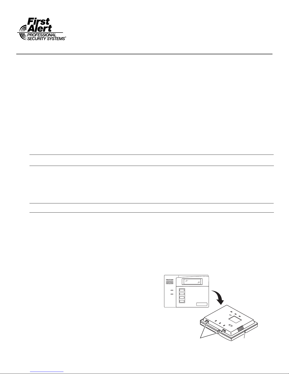
1. Push the two case release snaps at the bottom of the
keypad with the blade of a medium screwdriver (this will
push in the release snap), then pull that side of the case
back away. Insert the screwdriver in the side of the
keypad (between the front and back case) and gently
twist to release the side locking tab. Repeat for the other
side. Refer to Figure 1 for location of the case back
release snaps and locking tabs.
2. Route the wiring from the control panel through the
opening in the case back. (See the control panel’s
instructions for proper wire run lengths.)
3. Mount the case back directly to a wall or electrical gang
box.
4. Connect the power and data wires from the control panel
to the terminals on the FA6150RF-GP as indicated in
the wiring table adjacent to Figure 2.
• RF jam detection when the receiver is enabled.
• Low-battery indications for the local wireless keys.
• A nominal range of 200' for the RF transmitters (some
transmitters have a shorter range).
• Wireless keys for control panels that do not support RF
themselves (such as FA110C).
• Sends status signals (Armed, Ready, etc.) to bi-directional
units such as 5804BDV and 5828/5828V.
5. Connect the wires for the relay output (if used) to the
terminals on the FA6150RF-GP’s PC board.
6. Reattach the keypad to its case back.
Note: Upon power-up or exit of the Program Mode, the FA6150RF-
GP alternately flashes "Ad" and the 2-digit keypad address
and the 2-digit receiver address on the display. Press any key
to display the system status.
ARMED
READY
NOTE:
TO REMOVE CASE BACK
PUSH IN THE TWO MOUNTING
SNAPS LOCATED ALONG THE
BOTTOM OF THE KEYPAD
AND LIFT UP.
RETAINING
SNAPS
Figure 1 – Removing the FA6150RF-GP Case Back
LOCKING
TAB
6150-006-V0
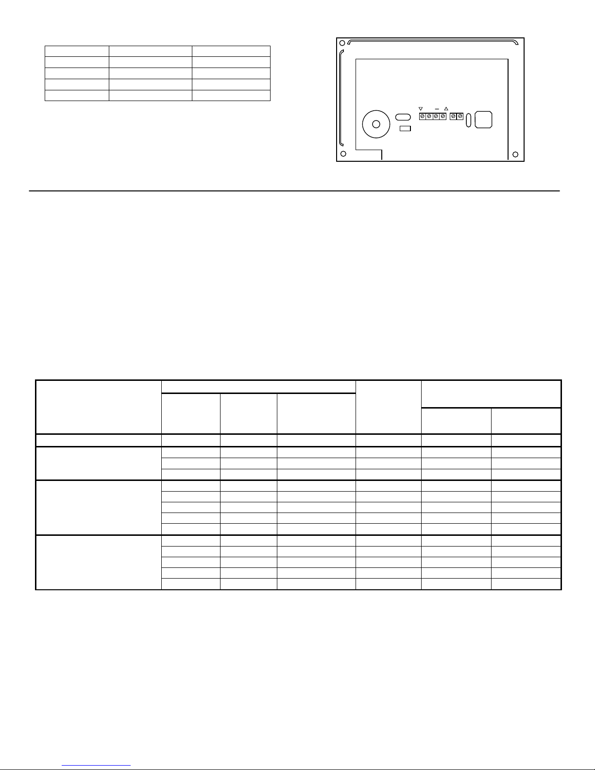
WIRING TABLE
Keypad Control Panel Wire Color
▲G Data In Green
− − Aux Pwr (GND)
Black
+ + Aux Pwr Red
▼Y Data Out Yellow
Note: NO (normally Open) and C (common) are the
connections for the relay output
C
NO
G
Y
+
6150RF-003-V2
Figure 2 - FA6150RF-GP Wiring Connections
APPLICATION GUIDELINES
Use the following guidelines when planning an installation:
• Local wireless keys (wireless keys programmed directly into the FA6150RF-GP) may be used regardless of
whether the RF receiver in the FA6150RF-GP is enabled or disabled.
• If using bi-directional devices, be sure to enable the transmitter module in the FA6150RF-GP.
• If transmitters are programmed into the control panel, be sure to enable the receiver. (Make sure you do not
exceed the number of receivers supported by the control panel.)
• If a local wireless key is programmed to arm/disarm or to trigger a relay on the control panel, a user code must be
entered into the FA6150RF-GP. This user code must also be programmed into the control panel.
• You must set the House ID only if you are using RF keypads and/or bi-directional devices; AND the House ID
Source is the FA6150RF-GP (Local).
FA6150RF-GP Application Guide
The following guide outlines how to program the wireless keys, RF receiver, and the House ID in the FA6150RF-GP
for your installation.
System Control Panel
FA110C, FA120C
FA130CP, FA142C, FA148C,
FA148CP
FA162C, FA168C, FA168C-GP
FA168CPS,
FA1220CV, FA1340C
Are you using
RF keys
beyond
system’s
capacity?
N/A N/A N/A FA6150RF-GP OFF Local [0]
NO NO N/A System ON [1] System [1]
YES NO N/A FA6150RF-GP ON [1] System [1]
YES YES N/A FA6150RF-GP OFF [0] Local [0]
NO NO NO System ON [1] System [1]
YES NO NO FA6150RF-GP ON [1] System [1]
YES YES NO FA6150RF-GP OFF [0] Local [0]
NO YES YES* System OFF [0] Local [0]
YES YES YES* FA6150RF-GP OFF [0] Local [0]
NO NO NO** System ON [1] System [1]
YES NO NO** FA6150RF-GP ON [1] System [1]
YES YES NO** FA6150RF-GP OFF [0] Local [0]
NO YES YES System OFF [0] Local [0]
YES YES YES FA6150RF-GP OFF [0] Local [0]
RF receivers
beyond
system’s
capacity?
RF keypads and/or
Bi-directional
devices on more
than 1 partition?
Program
Wireless Keys
Into
FA6150RF-GP Programming
Receiver
Enable
Options
House ID
Source***
* Two FA6150RF-GPs are needed for this application: one assigned to partition 1 and one assigned to partition 2.
** If using an RF keypad on only one partition, the FA6150RF-GP’s partition assignment in panel programming must match the partition.
*** If set for Local on a partition control, the FA6150RF-GP’s partition assignment must match the one programmed in the BD device.
- 2 -
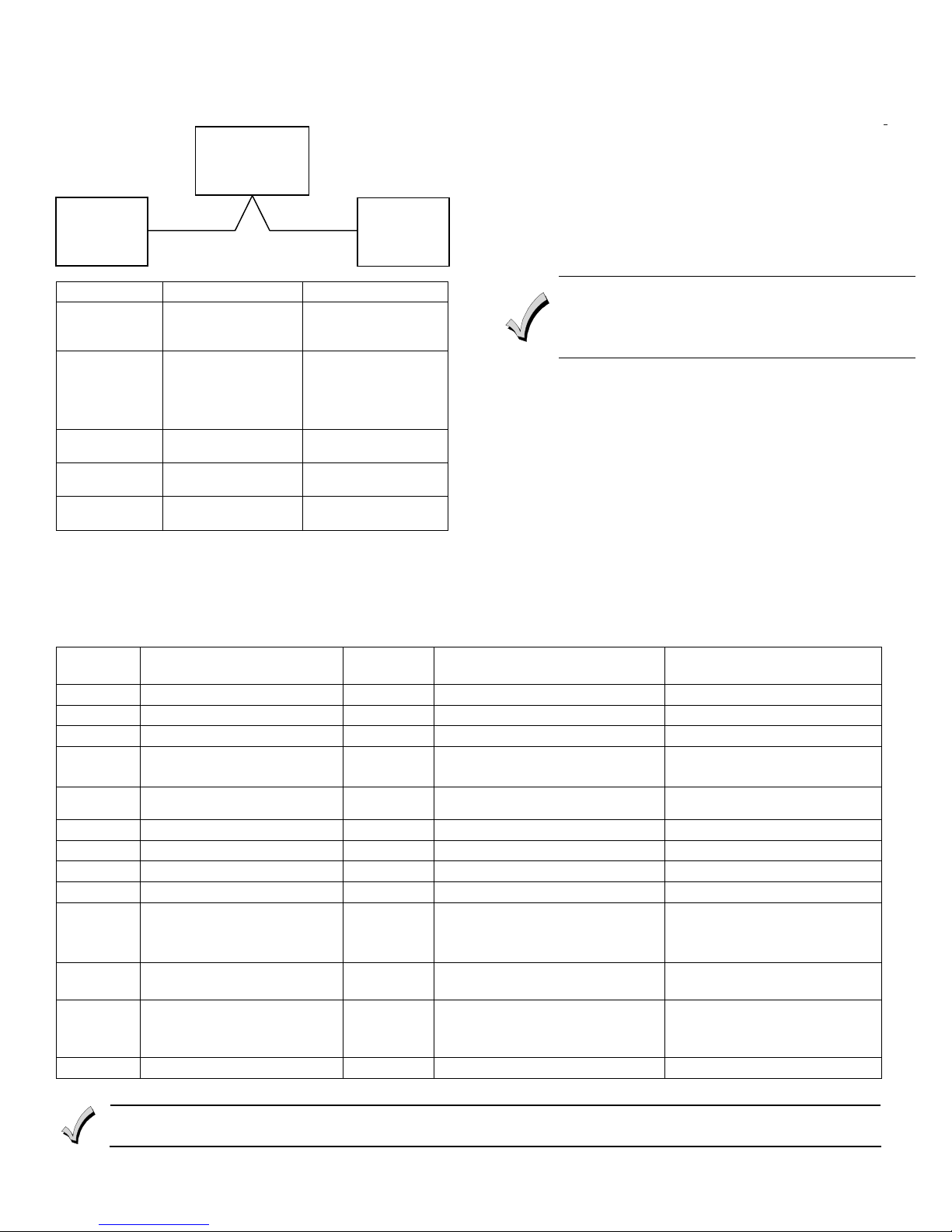
An example of an installation using two FA6150RF-GP
Keypad/Transceivers with 2-Way Wireless Devices (e.g.,
5828V) on Two Partitions is shown below:
CONTROL
PANEL
FA6150RF-GP
#1
FA6150RF-GP
#2
Settings FA6150RF-GP #1 FA6150RF-GP #2
Keypad: Must be assigned to
House ID: Match Partition 1
House ID
Source:
Receiver
Enable:
Transmitter
Enable:
Partition 1 in the
control panel
House ID in the
control panel and
House ID in Wireless
Device
System Local
On Off
On On
Must be assigned to
Partition 2 in the
control panel
Match House ID in
Wireless Device
shown. These values may be changed to suit the
installation.
Entering Program Mode
Press the [1] and [3] keys simultaneously for a few seconds,
within 30 seconds after applying power. The keypad beeps
three (3) times, and two dashes and two zeroes flash
alternately in the upper left-hand corner of the display. If
any other numbers or letters flash in the display, press the
[✻] key.
Note: The keypad will not enter programming mode if the system
has been armed before the FA6150RF-GP was powered up
or down.
Pressing the [1] and [3] keys 30 seconds or more after
applying power allows you to enter the User mode. This mode
allows you to enable and disable individual local wireless keys
(useful if, e.g., a user accidentally loses a wireless key). Refer
to the User Guide for instructions.
Programming Operations
Once you have entered the Program mode, you may move to
any program address simply by entering the program
address number. The FA6150RF-GP will automatically exit
the Program mode if no keys are pressed for 90 seconds.
While in the Program mode:
• Pressing the [✻] key stores the information displayed,
then moves you to the next prompt, and the keypad beeps
twice.
• Pressing the [#] key erases the current information and
PROGRAMMING THE FA6150RF-GP
The FA6150RF-GP is shipped with pre-programmed default
values. Later in these instructions are diagrams showing
the wireless keys' loops and their default functions.
Regardless of which wireless key you use (even if it is one
not shown), loops 1-4 are defaulted for all eight devices as
Program
Address
Description Display Choices Default
moves you back so you may enter the correct information.
Enter a program address (e.g., press [1] for Keypad
Address; [2] for Receiver Address) to set the parameters in
the FA6150RF-GP.The following chart lists the program
addresses, the keypad display, and the choices.
1 Keypad Address cA 01-31 31
2 Receiver Address rA 00-30 00
3 House ID HI 01-31 10
4 House ID Source hS 1 = System
0 = Local
5 Wireless Key Editing d- Enter Existing Device Number
1 System
6 Receiver Enable rE 1 = On 0 = Off 1 Enable
7 Transmitter Module Enable tE 1 = On 0 = Off 1 Enable
8 Wireless Key Auto Enroll d* Enter Serial Number
8 then 2 Wireless Key User Code u4 Enter 4-Digit User Code
8 then 4 Wireless Key Loop Function Ln Enter Loop Number then Function
8 then 5 Wireless Key On-Board Relay
Assignment
9 Restore Defaults EE 1 = Restores Defaults
0 High Security Mode✝ En 1 = Enable; 0 = Disable 0 Disable
* The keypad will display the next number that can be enrolled (i.e., “d3”)
✝ When operating the system in High-Security mode, non-encrypted wireless keys will not function.
(See Wireless Key Function Chart)
o- Enter Loop Number then Relay
Action
Any Other Key = Does Not
Restore Defaults
- 3 -
Loop 2 1 (Disarm)
Loop 3 2 (Arm Away)
Loop 4 3 (Arm Stay)
Loop 1 Close for 2 Seconds
 Loading...