

Page 1
Indoor/Outdoor
Analog Wired Cameras and DVR
Model 4800
USER'S MANUAL
Page 2

©2010 Lehigh Consumer Products, LLC
All rights reserved. Distributed by Lehigh Consumer Products, LLC, Macungie, PA 18062. Due to
continuing product development, the product inside the packaging may look slightly different than
the one on the package.
Lehigh Consumer Products, LLC is a subsidiary of Jarden Corporation (NYSE: JAH). To obtain
warranty service, contact the Consumer Affairs Division at 1-800-323-9005, Monday through
Friday, 7:30 a.m. - 5 p.m., Central Standard Time.
Made in China
M08-0246-000
Page 3

Table of Contents
1 Safety ...........................................................................................................................1
Safety Precautions ........................................................................................................................... 1
FCC Compliance ............................................................................................................................. 1
Disposal ........................................................................................................................................... 2
2 Getting to Know Your 4800 DVR................................................................................3
Check Package Contents.................................................................................................................. 3
Product Features .............................................................................................................................. 3
Product Overview ............................................................................................................................ 4
DVR Front Panel ..................................................................................................................... 4
DVR Rear Panel....................................................................................................................... 5
Remote Control........................................................................................................................ 6
3 Setting Up ....................................................................................................................7
Installing a Hard Disk Drive............................................................................................................ 7
Basic Hardware Installation............................................................................................................. 8
PTZ Control Connections (Option) ......................................................................................... 8
Mounting a Camera ................................................................................................................. 9
Installing and Connecting the Cameras and DVR ................................................................... 9
4 Getting Started .......................................................................................................... 11
Start Up.......................................................................................................................................... 11
Main Menu .................................................................................................................................... 12
Displaying the Status Bar, Tool Bar, or Single Channel View............................................... 12
Status Bar............................................................................................................................... 13
Tool Bar ................................................................................................................................. 14
Tool Bar Menu Options ................................................................................................................. 15
System Configuration ............................................................................................................15
Manual Recording.................................................................................................................. 15
Video Playback ...................................................................................................................... 16
Video Backup......................................................................................................................... 18
PTZ Control (Option) ............................................................................................................19
Screen View Modes ...............................................................................................................21
Screen Layout Adjustment..................................................................................................... 22
Channel Status Display ..........................................................................................................23
5 DVR Settings..............................................................................................................24
System Configuration Menu.......................................................................................................... 24
System.................................................................................................................................... 26
Language................................................................................................................................ 27
Video Standard....................................................................................................................... 27
VGA Setting........................................................................................................................... 27
Time Format........................................................................................................................... 27
Time Setting........................................................................................................................... 28
Page 4

Table of Contents
Model 4800 User's Manual
Password Setting.................................................................................................................... 29
Advanced Settings ................................................................................................................. 30
Adduser............................................................................................................................. 30
Deluser.............................................................................................................................. 30
Authority Manage............................................................................................................. 31
Record............................................................................................................................................ 32
Video Channel........................................................................................................................ 33
Record Schedule .................................................................................................................... 33
Record Quality....................................................................................................................... 34
Record Frame Rate ................................................................................................................ 34
Record Source........................................................................................................................ 35
OSD Setting ........................................................................................................................... 35
Record Resolution.................................................................................................................. 35
Advanced Setting................................................................................................................... 35
Video.............................................................................................................................................. 36
Camera Channel..................................................................................................................... 37
PTZ Protocol.......................................................................................................................... 37
PTZ Baud Rate....................................................................................................................... 37
PTZ ID ................................................................................................................................... 37
Color Setting .......................................................................................................................... 37
Motion Detection ................................................................................................................... 38
Mosaic.................................................................................................................................... 39
Advanced Settings ................................................................................................................. 40
Motion Handling............................................................................................................... 40
Video Loss Handling ........................................................................................................ 41
Channel Name Settings..................................................................................................... 42
Net ................................................................................................................................................. 43
Network ................................................................................................................................. 44
HTTP Port.............................................................................................................................. 44
Command Port ....................................................................................................................... 44
Media Port.............................................................................................................................. 44
Next Page............................................................................................................................... 45
PPPoE Setting...................................................................................................................45
PPPoE IP........................................................................................................................... 46
DNS Address .................................................................................................................... 46
DDNS ............................................................................................................................... 47
Auto Register.................................................................................................................... 47
File Sharing....................................................................................................................... 48
Mobile Port ....................................................................................................................... 48
Email Setting .................................................................................................................... 48
Alarm ............................................................................................................................................. 50
Alarm Input Channel.............................................................................................................. 51
Alarm Input Type ................................................................................................................... 51
Event Handling ...................................................................................................................... 51
Advanced Settings ................................................................................................................. 52
Event Handling ................................................................................................................. 52
Alarm Setting.................................................................................................................... 52
Alarm Zoom Out .............................................................................................................. 53
Page 5

Table of Contents
Model 4800 User's Manual
Maintenance................................................................................................................................... 54
Log View................................................................................................................................ 55
Upgrade.................................................................................................................................. 55
HDD Manage......................................................................................................................... 56
HDD Capacity........................................................................................................................ 57
Hardware Version................................................................................................................... 57
Software Version.................................................................................................................... 57
Software Release Date ...........................................................................................................57
Save ............................................................................................................................................... 58
Save & Exit............................................................................................................................ 58
Exit......................................................................................................................................... 58
Restore Defaults..................................................................................................................... 59
Logout.................................................................................................................................... 59
6 Web Browser Operation ...........................................................................................60
Enabling Download of an Unsigned ActiveX Control .................................................................. 60
Web Browser Login Screen ........................................................................................................... 61
Web Browser Main Window.......................................................................................................... 61
Tools Bar........................................................................................................................................ 63
DVR Parameters .................................................................................................................... 63
Server................................................................................................................................ 63
Channel............................................................................................................................. 65
Serial................................................................................................................................. 70
Alarm ................................................................................................................................ 71
User................................................................................................................................... 73
Device............................................................................................................................... 75
State .................................................................................................................................. 76
Talk-Back ............................................................................................................................... 77
Playback................................................................................................................................. 77
Search ............................................................................................................................... 78
Download.......................................................................................................................... 79
Device Log............................................................................................................................. 80
All Query Kinds................................................................................................................ 81
Query Kind by Time......................................................................................................... 81
Query Kind by Type ......................................................................................................... 81
Query Kind by Time and Type ......................................................................................... 83
Local Storage ......................................................................................................................... 84
Screen View Buttons.............................................................................................................. 85
PTZ Control Panel ......................................................................................................................... 85
7 Mobile Phone Support..............................................................................................87
Windows Mobile............................................................................................................................ 87
Symbian S60 3rd Phone................................................................................................................. 89
Sample Installation Process ................................................................................................... 89
Menu Buttons and Program Interface .................................................................................... 90
Setup ...................................................................................................................................... 91
Symbian Supported Mobile Phones............................................................................................... 92
Apple iPhone ................................................................................................................................. 94
Page 6

Table of Contents
Model 4800 User's Manual
8 Troubleshooting.........................................................................................................96
9 Technical Information ...............................................................................................98
Warranty.......................................................................................................................100
Product Limited Warranty............................................................................................................ 100
Warranty Exclusions .................................................................................................................... 100
Obtaining Service ........................................................................................................................ 101
Page 7

SAFETY PRECAUTIONS
Do not drop, puncture, or disassemble the cameras or DVR.
Do not tug on the power adapter. Use the plug to remove it from the wall.
Do not expose the cameras or DVR to high temperatures.
For your own safety, avoid using the DVR when there is a storm or lightning in
your area.
Use the cameras and DVR with care. Avoid pressing hard on the cameras or
DVR body.
Do not crush or damage the power cable.
FCC COMPLIANCE
Chapter 1
Safety
This device complies with Part 15 of the FCC Rules. Operation is subjected to the
following two conditions: (1) this device may cause harmful interference, and (2) this
device must accept any interference received, including interference that may cause
undesired operation.
This equipment has been tested and found to comply with limits for a Class B digital
device, pursuant to Part 15 of the FCC Rules. These limits are designed to provide
reasonable protection against harmful interference in residential installations. This
equipment generates, uses, and can radiate radio frequency energy and, if not installed and
used in accordance with the instructions, may cause harmful interference to radio
communications.
However, there is no guarantee that interference will not occur in a particular installation.
If this equipment does cause interference to radio or television equipment reception, which
can be determined by turning the equipment off and on, the user is encouraged to try to
correct the interference by the following measures:
Reorient or relocate the receiving antenna.
Increase the separation between the equipment and the receiver.
Connect the equipment into an outlet on a circuit different from that to which the
received is connected.
Consult the dealer or an experience radio/TV technician for help.
Notice: Changes or modifications to the product could void the user's
authority to operate the product.
1
Page 8

Safety
Model 4800 User's Manual
DISPOSAL
These symbols indicate that it is prohibited to dispose of these batteries in
the household waste. Take spent batteries that can no longer be charged to
the designated collection points in your community.
2
Page 9

Chapter 2
Getting to Know Your 4800 DVR
Congratulations on purchasing your First Alert Security product. First Alert has been helping
families and businesses stay safe for over 50 years. By having a First Alert Security System,
you’re taking the first step in protecting your home or business from damage or theft. We’re
watching, even when you’re not.
CHECK PACKAGE CONTENTS
Unpack the carton and check the contents for damage. Contact your supplier or dealer
immediately if any part is missing or damaged.
320GB H.264 Web-Ready DVR System (1)
Power Supply (1)
Wired Indoor/Outdoor Cameras (4)
Camera Stands (4)
Mounting Kits (4)
60 ft BNC Cables (4)
Splitter Cable (1)
Remote Control (1)
Mouse (1)
Installation CD (1)
User's Manual (1)
PRODUCT FEATURES
H.264 advanced auto compression
Mobile device / web-ready system
2 USB ports for data backup and mouse operation
Equipped with 320GB hard drive
Includes 30 infrared LEDs for night vision
Includes 60 ft BNC cables
3
Page 10
Getting to Know Your 4800 DVR
Model 4800 User's Manual
PRODUCT OVERVIEW
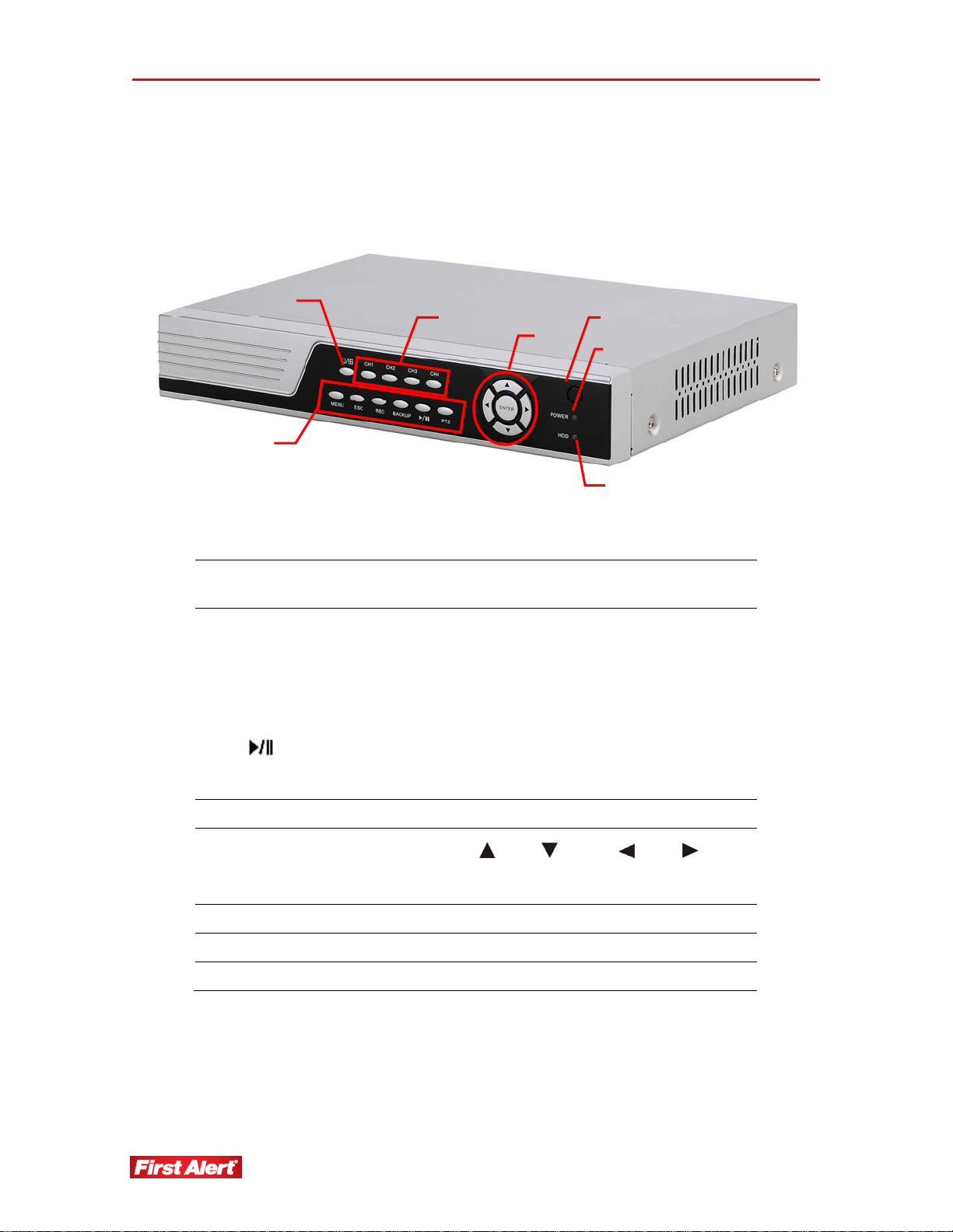
DVR FRONT PANEL
1
2
3
5
4
6
7
FULL/
1
QUAD
MENU Access main menu
ESC Exit the active window
REC Start/stop manual recording
2
BACKUP Open video search and backup menu
PTZ* Pan-Tilt-Zoom high-speed dome camera functions
3 CH1–CH4 Select channel
Navigation
buttons
4
ENTER Confirm/select operation
5 IR Window Infrared sensor for remote control
6 POWER Power LED
7 HDD HDD status LED
Select full-screen output video from Channel 1, 2, 3, or 4 or
all channels simultaneously (quad)
Play/Pause in playback mode; open video search and
playback menu
Cursor movement:
= up, = down, = left, = right
* Cameras supplied with 4800 system are not equipped with PTZ feature.
4
Page 11
Getting to Know Your 4800 DVR
Model 4800 User's Manual
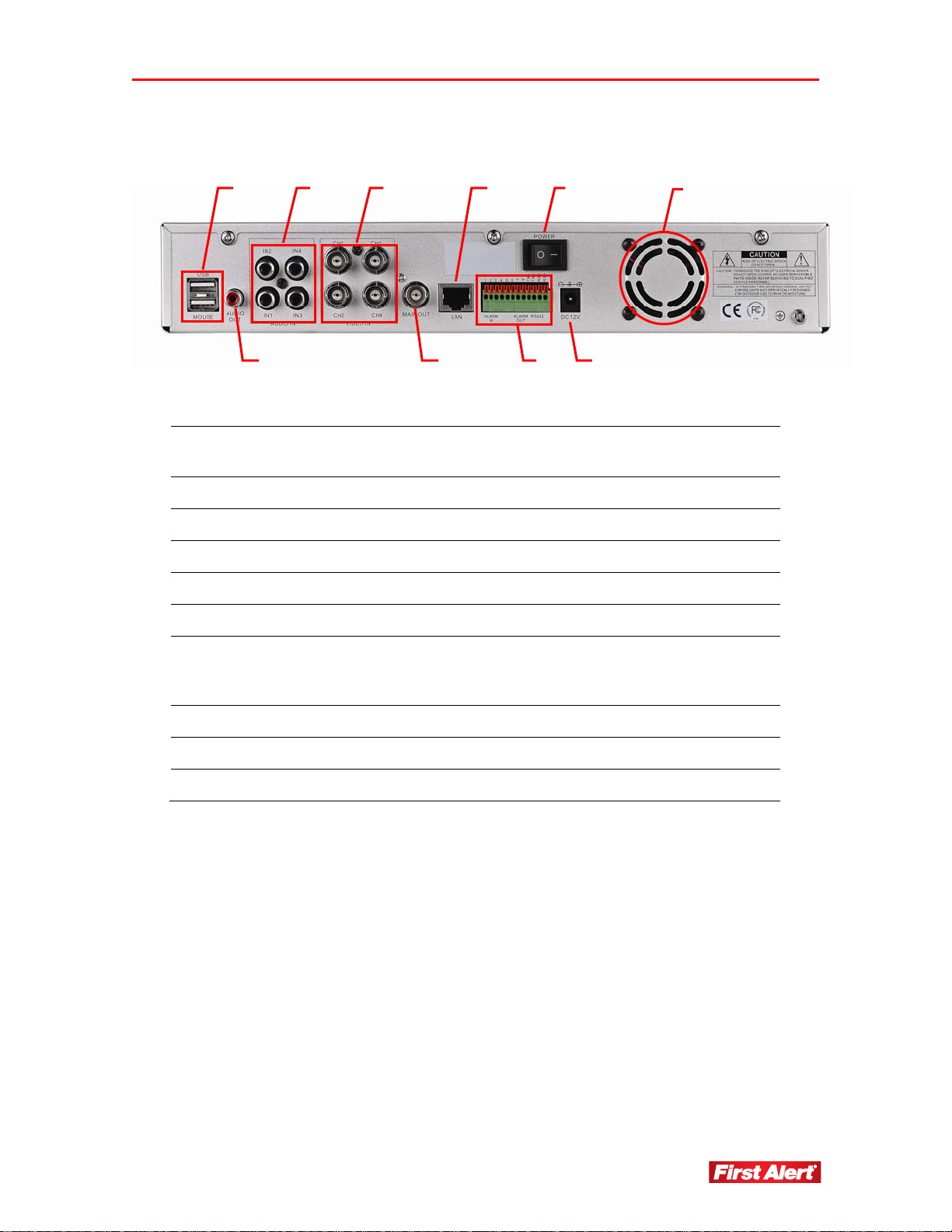
DVR REAR PANEL
1 3 4
2
6 8
5
7 9
1 USB Ports
2 Audio Output 1-channel audio output (2Vp-p, 600 )
3 Audio Input 4-channel audio input (2Vp-p, 600 )
4 Video Input 4-channel video input, BNC (1Vp-p, 75 )
5 Video Output Output to display monitor, BNC (1Vp-p, 75 )
6 Ethernet RJ-45 10/100 Base-T Ethernet port
USB ports for backup devices (flash drive, DVD recorder)
and mouse
10
ALARM IN
7
9 Power Power switch
9 DC 12V Power input
10 Fan Cooling fan air intake
ALARM OUT
RS-422/RS-485
Alarm input (1-4, 5-6, Ground) – external sensor devices
Alarm output (7-8) – external alarm devices
PTZ camera control (9-12)
Page 12
Getting to Know Your 4800 DVR
Model 4800 User's Manual
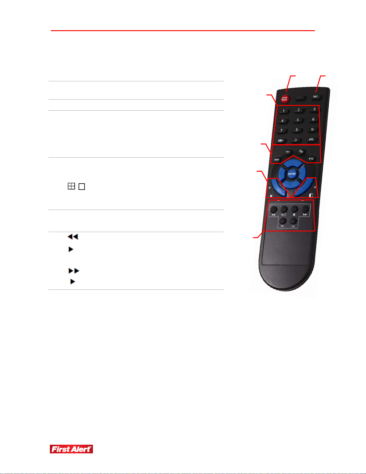
REMOTE CONTROL
1 Alarm Reset Clear the alarm input or alarm output
status
2 REC Start manual recording
Number/Channel
buttons
3
DEL
MENU
ESC
4
PTZ*
Enter values 0–9 in menus when in
live viewing
Select channel to view when in fullscreen
Delete
Open main menu
Return to previous menu
Switch between quad and split-screen
displays
Open PTZ control window
1 2
3
4
5
5
/||
6
|
|
Adjust brightness
Adjust contrast
Play in slow mode/rewind
Play/Pause
Stop
Fast forward
Go to next frame
6
* Cameras supplied with 4800 system are not equipped with PTZ feature.
6
Page 13
Chapter 3
Setting Up
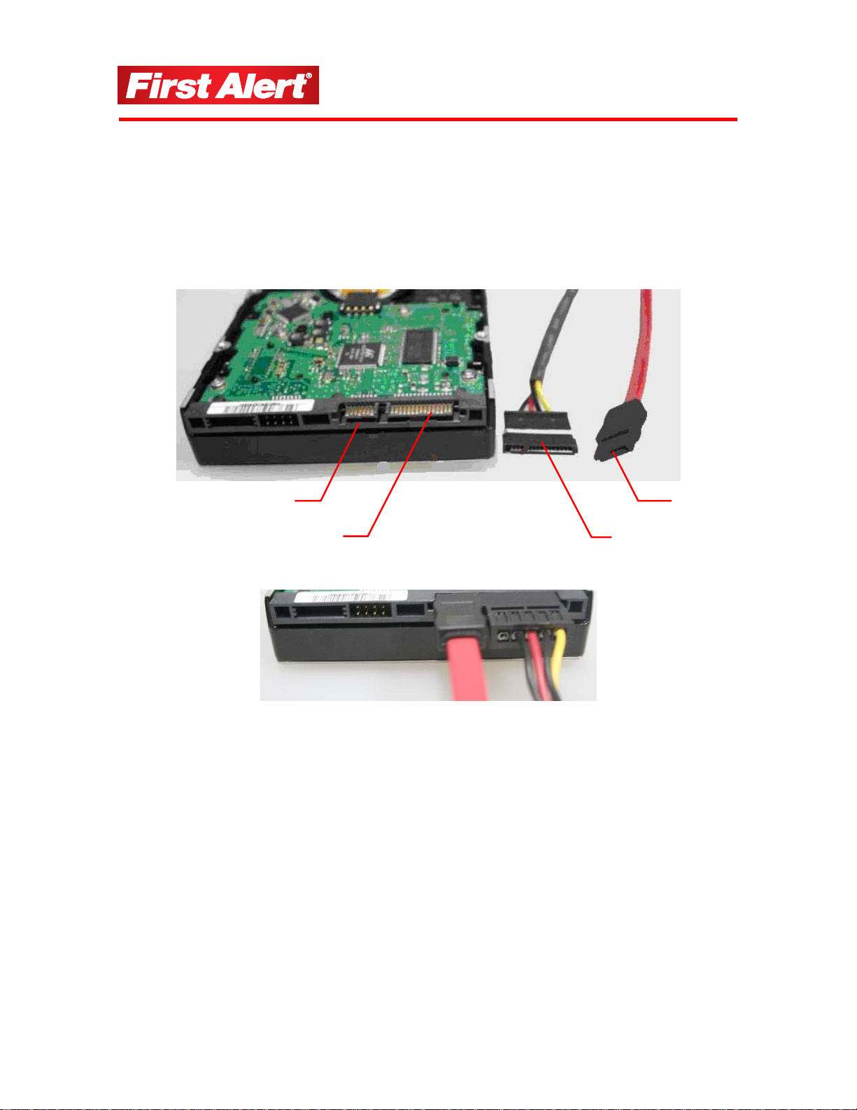
INST ALLING A HARD DISK DRIVE
1 Install a hard disk drive (HDD) in the DVR following the instructions provided by the
HDD manufacturer. Connect the data and power cables to the appropriate sockets.
data input
socket
power input
socket
power cable
data cable
connector
2 Format the HDD using the DVR before attempting to record because the standard PC
formatting is not compatible. Use the Maintenance tab on the Tool Bar Main Menu
(See Chapter 5).
Note: Depending on the size of the HDD, formatting can take several minutes.
7
Page 14

Setting Up
Model 4800 User's Manual
BASIC HARDWARE INSTALLATION
Cameras
Connect each camera output to the video input socket in the rear panel of the DVR
using appropriate cable. The video input interface is a standard BNC connector,
1Vp-p, 75 Ω. Keep the video signal cable away from strong electromagnetic and
electric interference.
Audio Connection
Connect the audio input to a standard RCA socket, 2Vp-p, 600 Ω. Keep the audio
signal cable away from strong electromagnetic and electric interference.
Note: Only the DVR has audio capability; the cameras do not have audio.
Monitor
Connect the main output connector to a TV input with a BNC-to-RCA cable.
Power
Use the 12V DC adapter supplied for connecting the DVR and the camera with the
power source.
Alarm Input/Output
Connect Alarm In 1-4 to N.O. (Normally Open) or N.C. (Normally Closed) alarm
connectors and one Ground connection. Connect Alarm Out to the corresponding
connections and Ground accordingly. (See Chapter 5, Alarm Input Type.)
Ethernet
Connect a standard RJ-45 twisted-pair Ethernet cable to the Ethernet connector for
remote access to the video images from the cameras via LAN or the Internet.
USB
Connect the mouse, USB flash drive, USB portable HDD, USB portable DVD
recorder to the DVR USB port. The DVR supports only FAT32 file USB devices.
PTZ CONTROL CONNECTIONS (OPTION)*
Connect the PTZ control jacks to the corresponding RS422/RS485 TX+ and TX-interfaces
on the rear panel of the DVR. See the PTZ camera manual for descriptions of protocols,
baud rates, and IDs.
* Cameras supplied with 4800 system are not equipped with PTZ feature.
8
Page 15
Setting Up
Model 4800 User's Manual
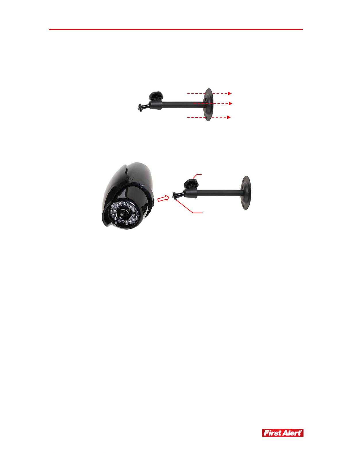
MOUNTING A CAMERA
1 Select the position for the camera and secure the camera stand. (Use an appropriate
screw type for the mounting surface.)
2 Screw the camera onto the stand. Tighten the lock nut.
thumb screw
lock nut
3 Adjust camera to the proper view angle. Make sure the lens is upright relative to the
subject. Tighten the thumb bolt.
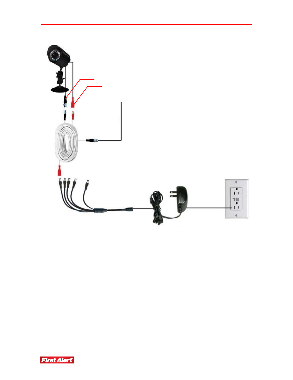
INSTALLING AND CONNECTING THE CAMERAS AND DVR
1 Connect the camera video connector into the BNC cable (supplied).
2 Connect the BNC connector on the other end of the cable to the video input on
the DVR.
3 Plug the camera power connector into the BNC cable.
4 Plug the other end of the camera power cable into one of the camera splitter
connectors.
5 Plug the power connector from the splitter to the power input on the rear panel of
the DVR.
6 Plug the 12V DC power supply adapter to the splitter.
7 Plug the power supply cord into an electrical outlet.
Page 16
Setting Up
Model 4800 User's Manual
BNC cable
video BNC connector
power connector
to DVR video input
to DVR DC input
splitter cable
12V DC power supply
10
Page 17
Chapter 4
Getting Started
This chapter provides information about the main operating menus and tool bar options. The
menus are used to configure the system and control the various functions of the DVR. The
user selects options from a series of menus and executes the actions using the DVR keypad,
the mouse or the remote control.
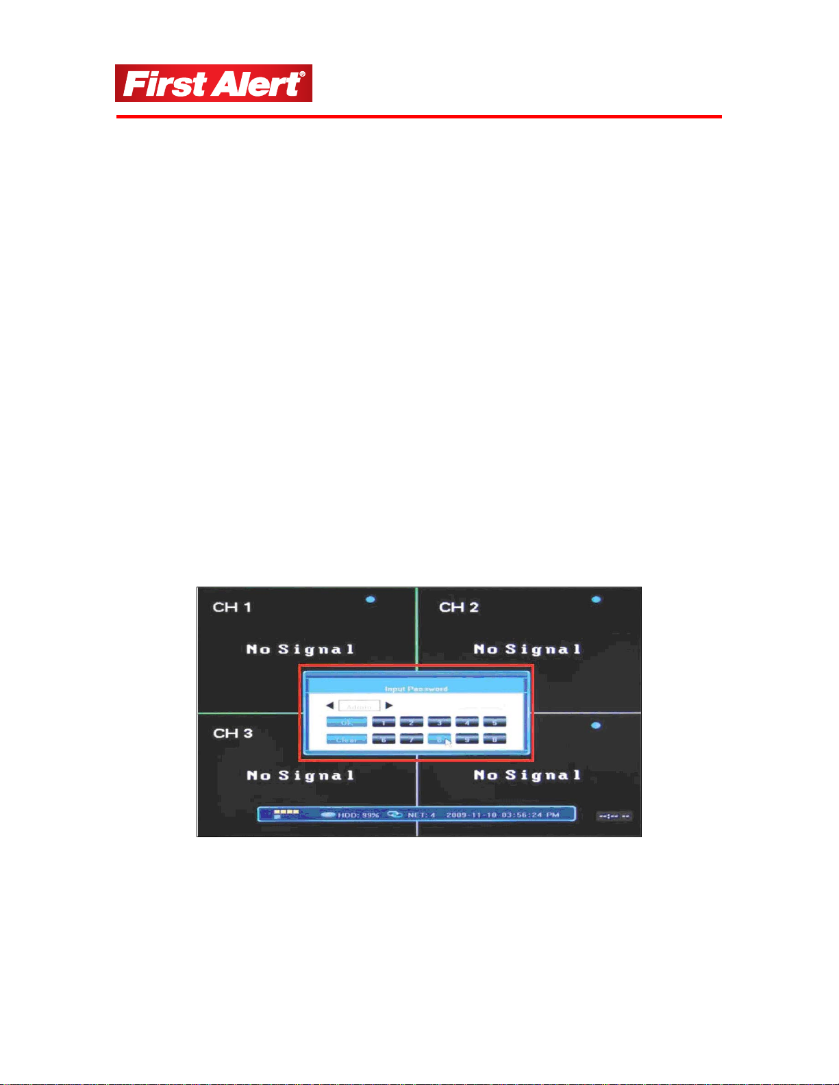
START UP
Power on the DVR and wait for the system to load.
Note: If you have not yet installed a hard disk drive in the DVR, a buzzer will sound
and a “No Hard Disk” message will appear on the screen. (See Chapter 3,
Setting Up.)
At log in, select your user account and enter your password. Choose the user account by
clicking arrow buttons on both sides of the account field (or using arrow keys on the
remote control) and enter the password using the numerical keypad in the lower part of the
Input Password window. Press OK to confirm or press CLEAR to clear the field and enter
another value.
By default, the system has two users: Admin and User with preset passwords. Only the
Admin (administrator) is able to change system settings.
Note: The default password for Admin is "888888"; User is "666666". Change your
password in the System Settings of the System Configuration Menu (see
Password Setting).
11
Page 18
Getting Started
Model 4800 User's Manual
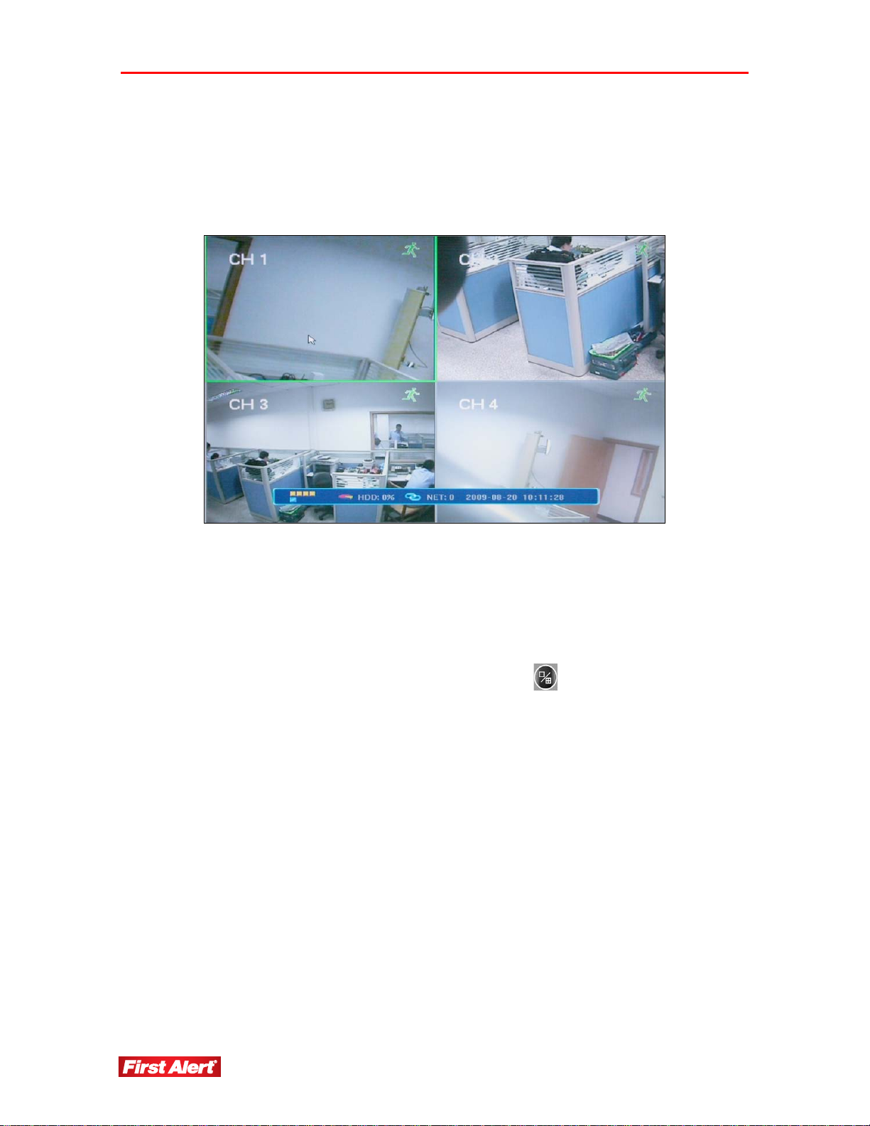
MAIN MENU
The Main Menu has four windows evenly distributed over the screen. Use the Main Menu
to access menu options and switch channel views, displaying either all channel feeds
simultaneously or a full-screen view of a selected channel.
DISPLAYING THE STATUS BAR, TOOL BAR, OR SINGLE CHANNEL VIEW
Right-click anywhere on the screen to display the Status Bar, Tool Bar, or neither.
To activate a single channel view from the multiple channel view, left-click twice on the
particular window or press the single/multiple view button
remote control. To return to the multi-screen view, double-click on the screen or press the
single/multiple view button on the DVR front panel or remote control.
on the DVR front panel or
12
Page 19
Getting Started
Model 4800 User's Manual
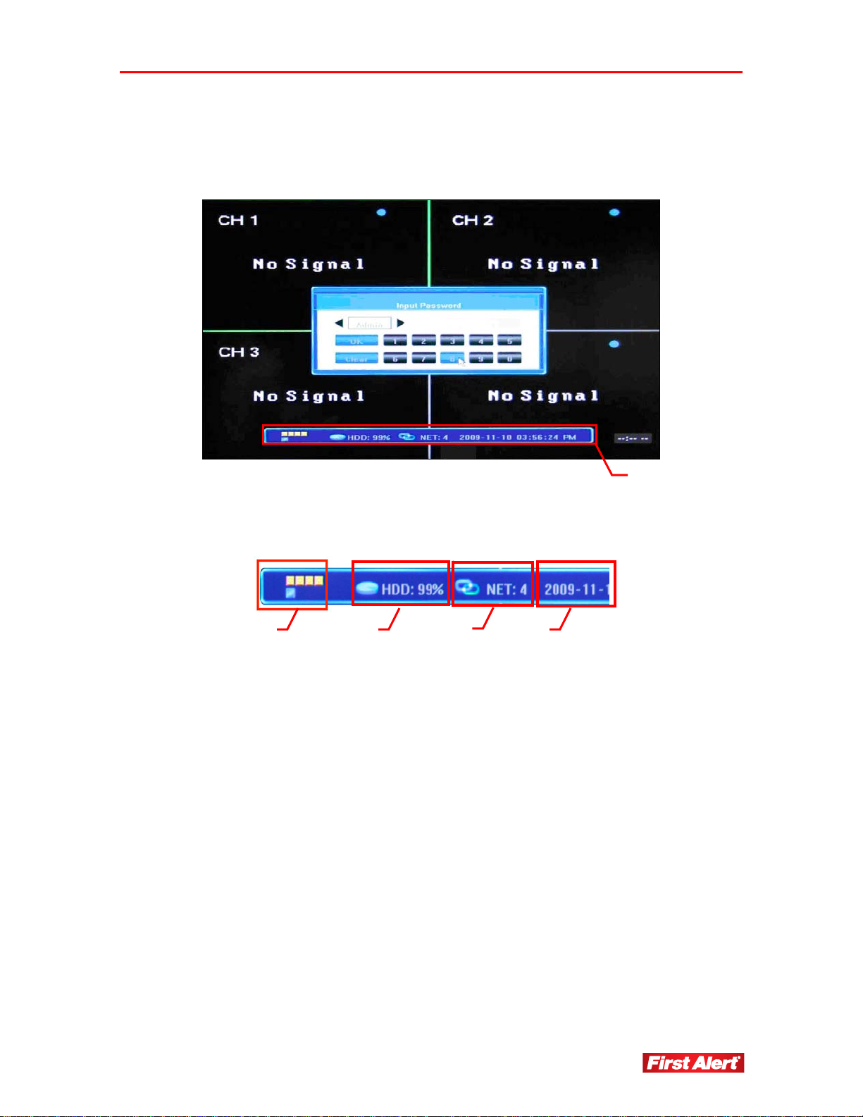
STATUS BAR
Click anywhere on the screen to display Status Bar at the bottom of the window.
Status Bar
On the far left of the bar, are five colored squares, indicating the alarm status:
1 2
3
4
1 Alarm input status for each of the four windows and indicates alarm output.
When alarm output is activated, color changes to red.
2 HDD usage (percentage).
3 Number of remote users accessing the system via the network/Internet (NET:X).
4 Current date/time in YYYY-MM-DD HH-MM-SS format.
Page 20
Getting Started
Model 4800 User's Manual
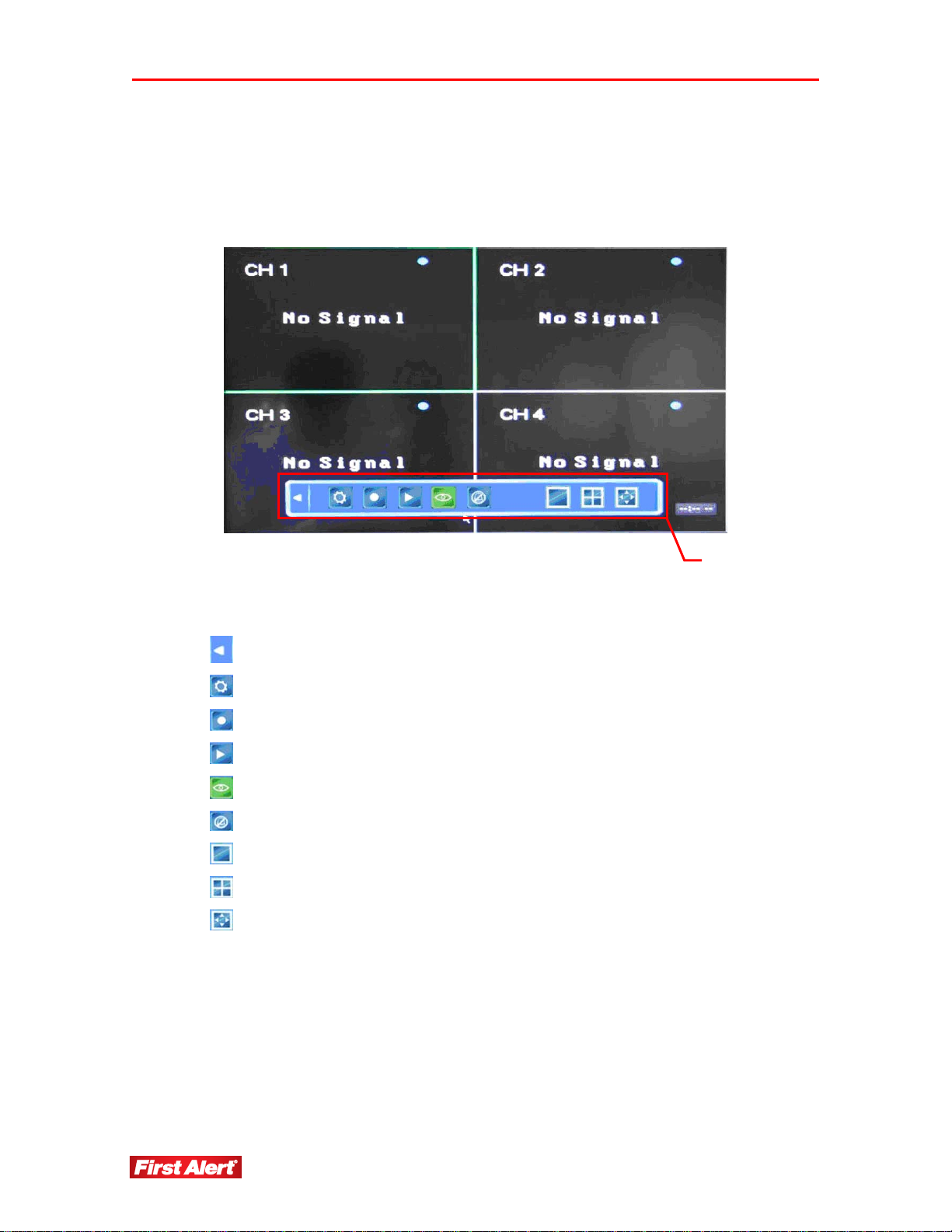
TOOL BAR
To display the Tool Bar, right-click the mouse anywhere on the screen, or press ENTER on the
front panel of the DVR or on the remote control.
The functions of the Tool Bar buttons are:
Hide the Tool Bar and return to the Status Bar
Access System Configuration menu
Start manual recording
Search, playback, and backup recorded files
Access PTZ menu*
Access current alarm information and cancel alarm notification
View single window
View quad window
Adjust window layout/position
Tool Bar
* Cameras supplied with 4800 system are not equipped with PTZ feature.
14
Page 21
Getting Started
Model 4800 User's Manual
TOOL BAR MENU OPTIONS
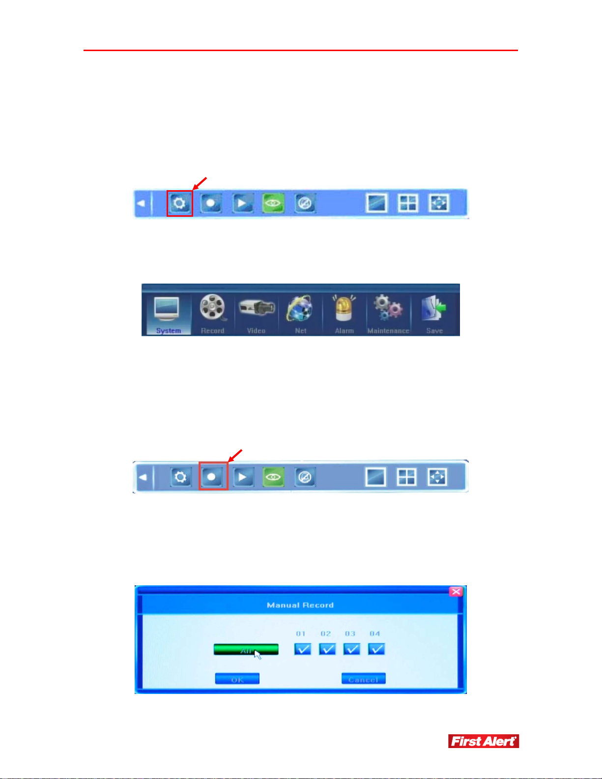
SYSTEM CONFIGURATION
To access the system configurations screen, click the System Configuration icon on the
Tool Bar.
Use the screen to adjust System, Record, Video, Net, Alarm, Maintenance, and Save
settings. See Chapter 5, DVR Settings for descriptions of the system configurations
settings.
MANUAL RECORDING
To record a video feed, click the Manual Record icon on the Tool Bar, or press REC on the
front panel of the DVR or on the remote control to access the Manual Record menu. Select
the channels you wish to record or choose record all to simultaneously record all four
channels. Press OK to confirm or press CANCEL to undo your choice.
There are three ways to record live video feed from the cameras: Manual, Scheduled, or
Alarm. If the recording schedule is in conflict with manual recording, the manual
recording will be processed first until stopped. Recording modes are displayed in the top
right corner of the menu. Manual recording mode is indicated onscreen with the grey icon.
See the Chapter 5, DVR Settings for descriptions of the record settings.
Page 22
Getting Started
Model 4800 User's Manual
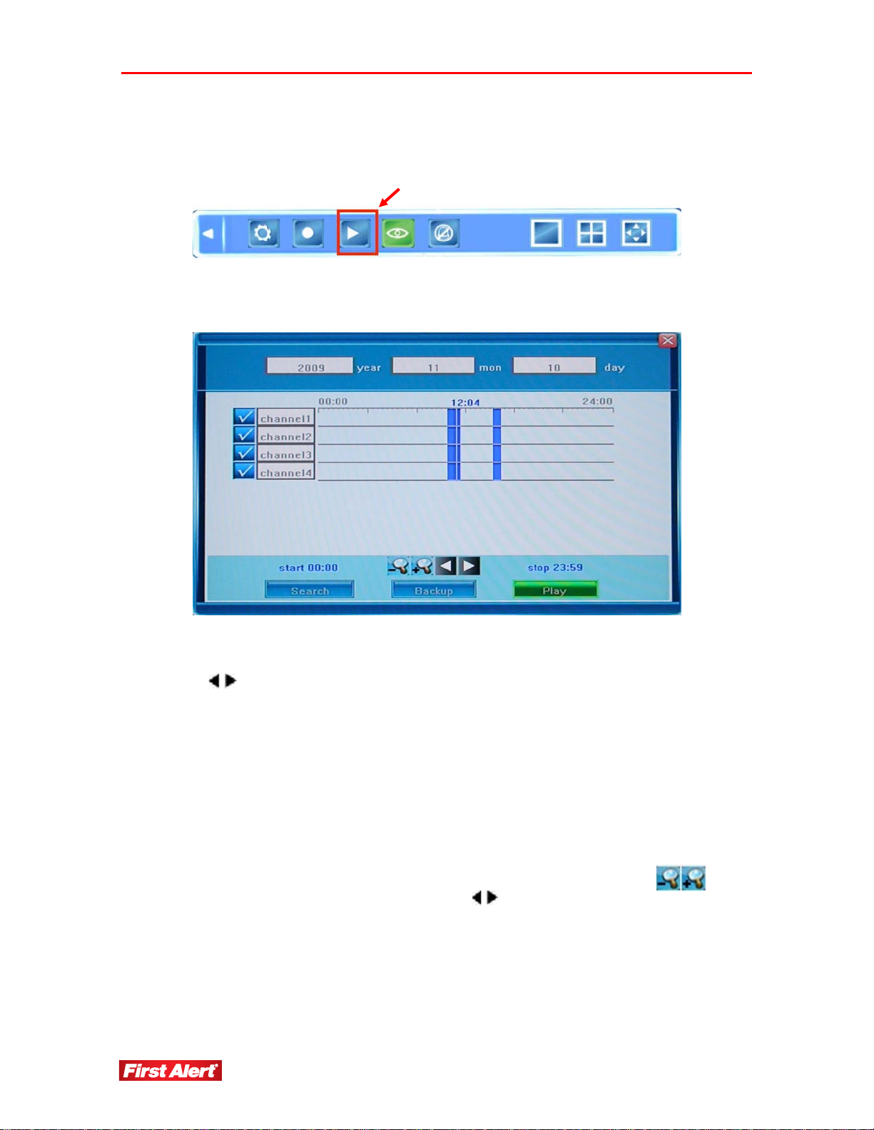
VIDEO PLAYBACK
To playback a recorded video, click the Record Search icon on the Tool Bar.
Use the Video Playback menu to select the date/time and channel you wish to view. See
Chapter 5, DVR Settings for descriptions of the playback settings.
To playback a certain video feed from a particular camera, indicate the time and camera
from which you want to receive information. If using the remote, navigate between fields
using the
buttons and modify the time using the ▲and ▼buttons. Press ENTER to
confirm your selection.
Using the mouse, position the cursor over the field and use the navigation buttons to
modify the values. After selecting the day, click SEARCH to locate the recordings from
that day.
Select the Start and Stop time on the time line positioned against the available channels
(choose the channel to view by selecting the checkbox next to each channel). Up to four
channels can be selected for playback. The start and stop times of the recording are
indicated by two vertical lines on the time line. If using the remote control, go to the
desired line using navigation buttons. To fine-tune the required time, use the
buttons to zoom in/out of the time line or use the
buttons to move along the time line.
Time values will display above the time line.
Using the mouse, left-click once to set up the start time, then left-click to indicate the stop
time. Right-click to cancel the marked time.
16
Page 23
Getting Started
Model 4800 User's Manual
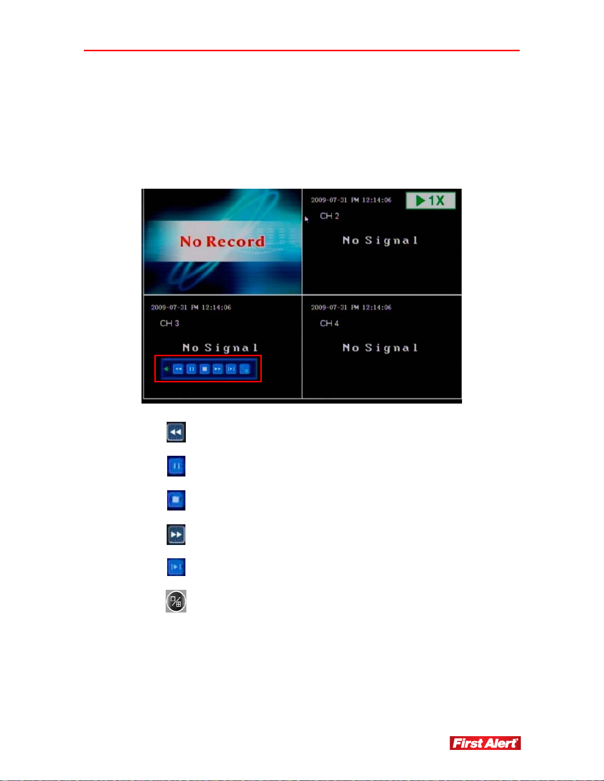
The available recordings will be represented by colored bars on the time line depending on
the type of recording (blue = common, green = motion detection triggered, red = alarm
triggered, and blue = manually made).
Click Play on the menu tool bar, or navigate to it and press ENTER on the front panel of
the DVR or remote control. The selected channels will playback in the view windows.
In Playback Mode, the playback control panel and the date/time of the played file display.
Fast rewind
Pause
Stop
Fast/Slow Forward (available speeds: 1x, 8x, 16x, 1/2x, 1/4x, and 1/8x)
Frame-by-frame view
Toggle single camera view and 4 camera view
Page 24
Getting Started
Model 4800 User's Manual
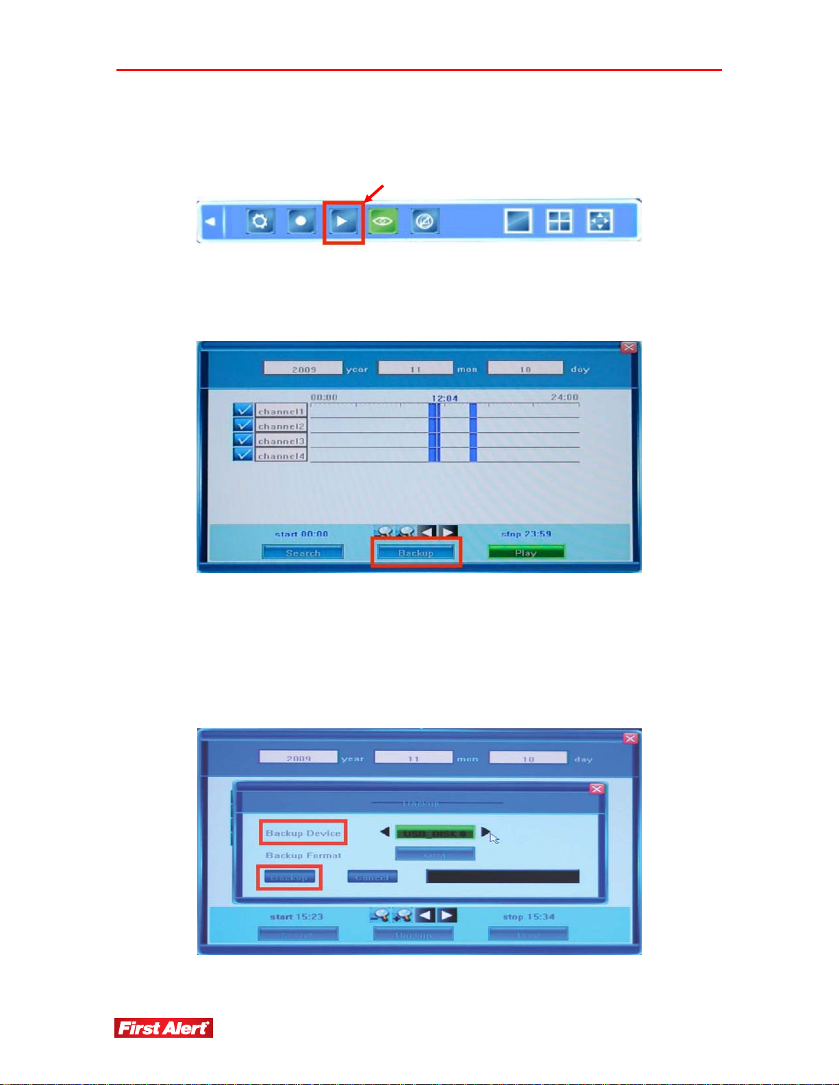
VIDEO BACKUP
To backup a video, click the Playback icon on the Tool Bar.
To backup the recorded footage, indicate which cameras and time interval you want to
save to an external source. Set the start and end time as described in Video Playback in this
chapter.
After setting the start and stop times, click the Backup button to access the Backup menu.
The system automatically detects all available backup devices and displays them in the
Backup Device field. Place the cursor over the field or use the arrow buttons view the
available choices. Press the arrows on each side of the field to toggle between options.
Note: If the system does not recognize connected devices or none are connected, a
warning message ("No Available Device") displays.
18
Page 25
Getting Started
Model 4800 User's Manual
Connect external media such as USB flash drives, portable USB HDDs, and USB DVD
recorders.
Note: The system supports the FAT32 file system for US B flash drives.
Choose either H.264 Raw, MP4, or AVI format for video backup.
H.264 Raw Format
Stored video files can be played by an H.264 player. Download an H.264 player
from http://www.videolan.org/vlc. Rename the stored video file from *.264 to
*.h264 and play the video on a VLC Media Player.
MP4 Format
The system automatically records special decoder components to USB flash
drives or DVD discs along with the video file. After installing this component on
a PC, use the Windows Media Player to play saved MP4 format video files. The
*.avi video files can be played by Windows Media Player.
To play backed up video on a PC:
1. Locate the compressed file WMP_MKiaFilter.rar on a USB flash drive or
CD/DVD where the video file was saved and decompress WMP_MKiaFilter.rar.
2. Execute InstallFilter.bat to install the decoder components.
3. Use the Windows Media Player to view the saved video.
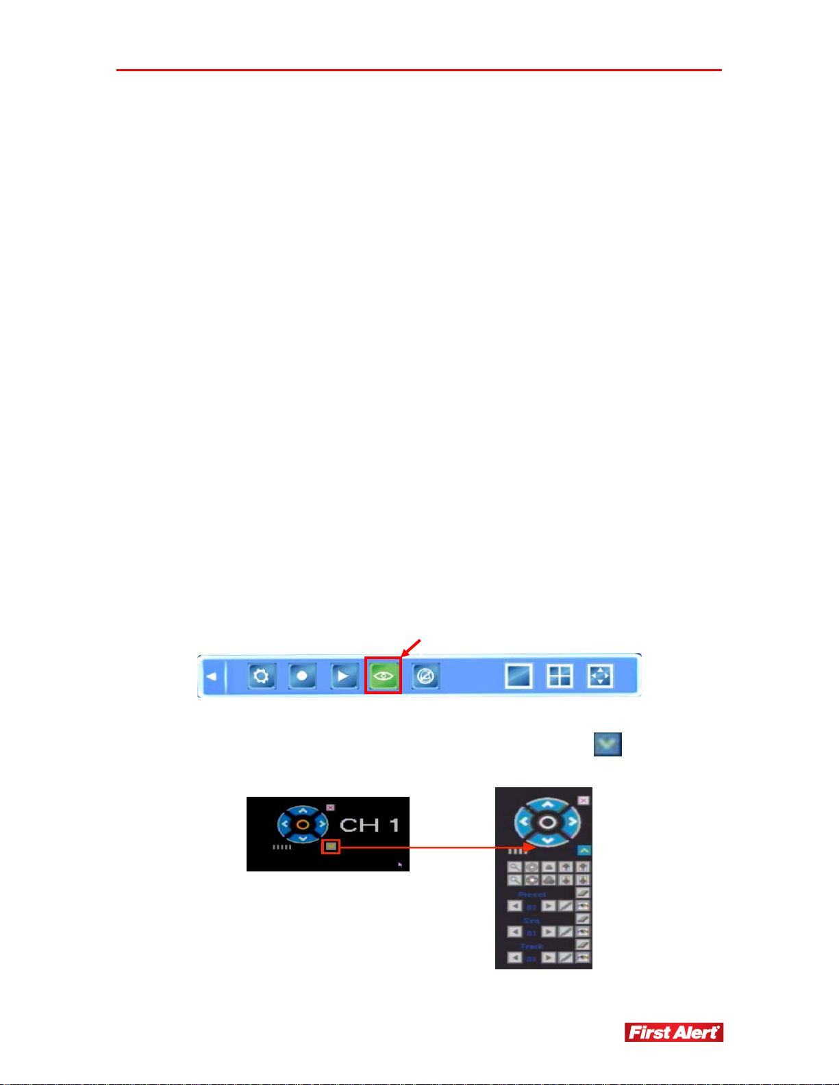
PTZ CONTROL (OPTION)*
PTZ control is available for cameras with the PTZ (Pan-Tilt-Zoom) option. Press the PTZ
control button to view the current video feed in single-screen mode.
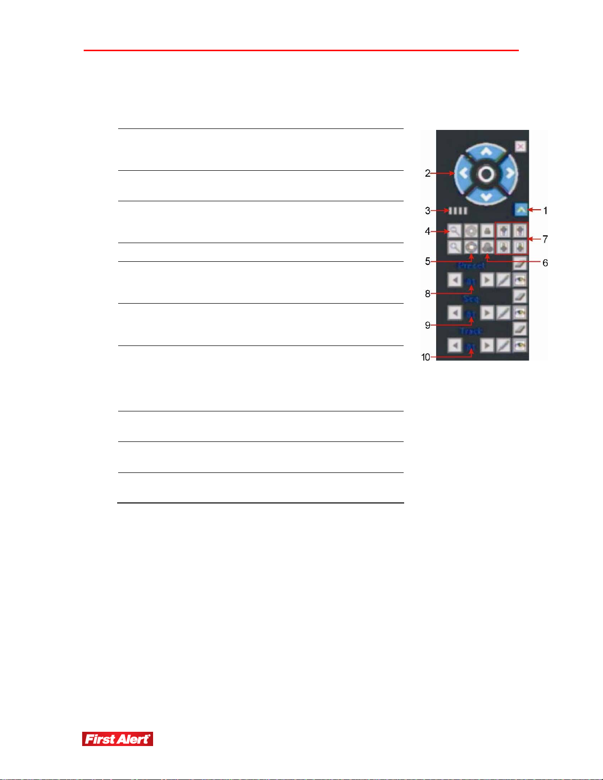
The PTZ menu displays in the top right corner of the screen. Use the navigation buttons to
determine the rotation of the camera. Click the drop-down menu button to display the
function panel.
* Cameras supplied with 4800 system are not equipped with PTZ feature.
Page 26
Getting Started
Model 4800 User's Manual
Menu functions may vary depending on the make and model of the PTZ camera used. For
a detailed description of available options, refer to the PTZ camera user's manual.
Toggle
Functional
1
Panel
Navigation
2
Buttons
3 Speed
4 Zoom Click to zoom in/out.
5 Iris
6 Focus
Toggle the panel view for the options
available on a PTZ camera.
Control the direction of the PTZ. (Refer
to the PTZ camera user's manual.)
Set the turning speed on a PTZ camera.
Use the mouse to click on the scale for
adjusting this setting.
Click to make the image brighter or
darker. (This function is disabled for
cameras with automatic iris adjustment.)
Click to focus in/out. (This function is
disabled for cameras with automatic
focus.)
7 Auxiliary
Preset
8
Point
9 Seq
10 Track
Preset Point Procedures
To set the pre-adjusted settings:
1. Select the preset number.
2. Adjust the camera as desired, including direction, focus, iris, and zoom values.
3. Click the Set button.
Click to open and to close auxiliaries.
Different functions respond to different
protocols. The auxiliaries include light,
wiper, power, etc. (Refer to the PTZ
camera user's manual.)
Preset camera position, focus, zoom, and
iris settings for easy access.
Sequence is a running route of the camera
that passes through multiple presets.
Track is a continuous running route of a
camera.
To call the pre-adjusted settings:
1. Select the preset number.
2. Click the Start button.
To clear/reset pre-adjusted settings:
20
Page 27

Getting Started
1. Select the preset number you want to clear or reset.
2. Click the Clear button.
Sequence Procedures
To set a sequence:
1. Select preset number.
2. Click the Set button.
3. Repeat steps 1 and 2 to add more presets if needed.
4. Click the Run button.
To clear a sequence:
1. Click the Clear button to clear sequence.
Track Procedures
To set a track:
Model 4800 User's Manual
1. Click on the track button
to start.
2. Move camera in the pattern you want it to run.
3. Click the track button again to finish the track setup.
4. Click the run button
5. Click the clear button
to run track. Click again to stop running.
to clear the track sequence.
SCREEN VIEW MODES
Use the screen view button on the Tool Bar to switch between single- and quad-screen
views.
Page 28
Getting Started
Model 4800 User's Manual
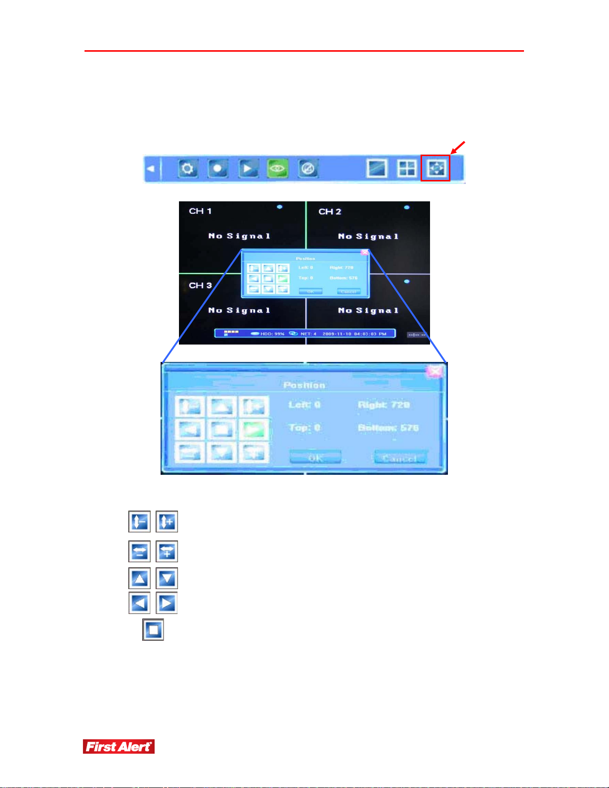
SCREEN LAYOUT ADJUSTMENT
Use the screen layout on the Tool Bar to access the Position screen.
Use the buttons to reposition the layout of a full image or a single-view.
Shrink/enlarge the window image vertically (creates a black margin at the
top and bottom).
Shrink/enlarge the window image horizontally (creates a black margin on
the left and right).
Move the window image up, down, left, right on the monitor (leaves black
margin on one side of the display).
Auto-stretch the window image centering it with equal circumference
OK
CANCEL
margins.
Confirm the adjusted position.
Cancel the current position.
22
Page 29

Getting Started
CHANNEL STATUS DISPLAY
Status icons display on the top-right corner of each channel image.
Channel has detected motion in motion detection mode.
Channel is in the scheduled recording mode.
Channel is in the motion-detection triggered recording mode.
Channel is in the alarm-triggered recording mode.
Channel is in the manual recording mode.
Model 4800 User's Manual
Page 30
Chapter 5
DVR Settings
This chapter provides an overview of the DVR system configuration menu and instructions for
setting operating parameters.
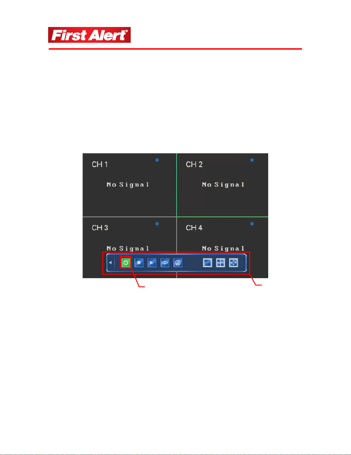
SYSTEM CONFIGURATION MENU
Click the System Configuration button on the Tool Bar to access the system configuration
menu (see the menu hierarchy on the next page). To display the Tool Bar, right-click
anywhere on the window or press ENTER on the front panel of the DVR or remote control.
System Configuration Button
24
Tool Bar
Page 31

DVR Settings
Model 4800 User's Manual
Language
Video Standard
Video Channel
Record Schedule
Record Quality
Record Rate
Record Source
OSD Setting
Rec Resolution
Advanced
Network
IP Address
Subnet Mask
Gateway
HTTP Port
Command Port
Media Port
Next Page
Tool Bar
Setting
Manual Record
Record Search
PTZ
Clear Alarm
1/4 CH
Position
VGA Setting
Time Format
Time Setting
Password
System
Advanced
Record
Camera Channel
PTZ Protocol
PTZ Baud Rate
PTZ ID
Color Setting
Motion Detection
Video
Mosaic
Advanced
Net
Alarm Input Ch
Alarm Input Type
Alarm
Maintenance
Save
Event Handling
Advanced
Log View
Upgrade
HDD Manage
HDD Capacity
Hardware Version
Save & Exit
Software Version
Exit
Release Date
Restore Defaults
Logout
Page 32

DVR Settings
Model 4800 User's Manual
SYSTEM
The System Configuration window provides access to seven sub-menus used to set the
DVR system. A section describing each sub-menu and their available options follows.
Language
Video Standard
VGA Setting
System
Time Format
Time Setting
Password
Add User
Advanced
Del User
Authority Manage
Click the System button on the System Configuration menu to access the System settings
sub-menu.
26
Page 33

DVR Settings
Model 4800 User's Manual
Select the general system settings for operating the DVR. Menu titles are on the left, and
the corresponding changeable/non-changeable values are in the fields to the right. A short
description of each setting displays when the cursor moves over the field name or, enter
the fields using the navigational buttons on the front panel of the DVR or the remote
control.
Use the arrow keys to the side of the field name to toggle through the available options.
Several tabs have options on more than one window. Press the Next Page or Advanced
Settings buttons to navigate between them.
LANGUAGE
Select the language for the DVR menu text and window displays. The change takes effect
immediately and does not require saving and exiting the menu.
VIDEO STANDARD
Select the system video standard (options: NTSC, SECAM, or PAL). The change takes
effect after saving and exiting the menu.
Note: Set the video standard to NTSC. If the system is set to PAL, the screen will
keep rolling and images will be unviewable.
VGA SETTING
NC
TIME FORMAT
Select the time format (options: 12-hour or 24-hour). The change takes effect after saving
and exiting.
Page 34

DVR Settings
Model 4800 User's Manual
TIME SETTING
Adjust the current date and time set on the DVR. Click the >> button to open a dialog box
and change the year, month, date, hours, minutes, and seconds. Click OK to confirm the
setting or click CANCEL to reject the change.
Note: To avoid possible confusion with the time stamps o n recorded and curr ently
recording files, stop all ongoing recording processes before altering the
system time and restart recording using the new settings.
28
Page 35

DVR Settings
Model 4800 User's Manual
PASSWORD SETTING
Modify the Administrator or User passwords. If logged in as Administrator, you can
change both passwords. If logged in as a User, you can only change the user password.
Enter the new password using the numerical keyboard. Click OK to confirm or click
CANCEL to reject the change.
Note: The default password for Admin is 888888. The default password for User is
666666. We recommend you select and enter a new password at system start
up. Keep a copy of the password in a secure location.
Page 36

DVR Settings
Model 4800 User's Manual
ADVANCED SETTINGS
The Advanced Settings menu (lower right-hand corner) has three options: Adduser,
Deluser, and Authority Manage.
DDUSER
A
Click Adduser to add a new user to the system. Use the keypad to input user information.
Click Enter to save.
ELUSER
D
Click Deluser to remove a user from the system. Highlight the user name and click Delete.
30
Page 37

DVR Settings
Model 4800 User's Manual
AUTHORITY MANAGE
Use the Authority Manage window to set a local and remote authority to access selected
system features. By default, only the administrator account is allowed to modify DVR
settings.
In the authority options window, click the box next to an option to issue that authority to
the user (check mark displays when selected). Click OK to confirm the setting or click
CANCEL to reject the change. Click the Common Setting button in the bottom-right
corner to return to the original window.
Page 38

DVR Settings
Model 4800 User's Manual
RECORD
The Record window provides access to eight sub-menus used to set the record parameters.
A section describing each sub-menu and their available options follows.
Video Channel
Record Schedule
Record Quality
Record
Record Frame Rate
Record Source
OSD Setting
Record Resolution
Sub CodeAdvanced Setting
Click the Record button on the System Configuration menu to access the Record Settings
sub-menu and adjust settings related to recording CCTV images to the HDD.
32
Page 39

DVR Settings
Model 4800 User's Manual
VIDEO CHANNEL
Use the arrow key to select the camera (channel) number whose settings you want to
modify (options: 1, 2, 3, 4, or All).
RECORD SCHEDULE
Create a schedule for recording tasks throughout the week so that only certain events are
recorded to the HDD. Select a color option button at the bottom of the screen and then
click on the hour in the graph or click and drag an area in any direction to highlight several
cells. Press OK to confirm the settings. The changes will take effect after saving and
exiting the menu.
For example, to set up the system to record non-stop during normal business hours, record
only alarm-triggered events during lunch time (recording will not occur unless an alarm
event happens) and then record only motion-triggered events at night time.
Note: Manual recording overrides all record settings until stopped by the user.
1
2
3
1 The current recording channel number being modification. The changes will be
applied to all available channels.
2 The weekly recording schedule for recording various kinds of events Sunday
through Saturday on a 24-hour basis. Weekdays are represented in the column
on the left and the hour line runs horizontally from 0 to 24 hours. One cell
equals one hour.
3 The recording type for each event/type is color-coded:
White: recording will not be performed during this time
Blue: recording full-time
Green: recording triggered by motion-detection
Red: recording triggered by an alarm
Page 40

DVR Settings
Model 4800 User's Manual
Yellow: recording triggered by an alarm or motion detection.
Select a color option button before highlighting time cells. Click on the hour in the graph
or click and drag an area in any direction to highlight several cells. Press OK to confirm
the settings. The changes will take effect after saving and exiting the menu.
Note: For motion detection recording, set both the motion detection sensitivity and
zone. See the Motion Detection Settings section below for details. For alarm
recording and alarm triggering settings, see the Event Handling section.
RECORD QUALITY
Select the quality level for recording audio/video. The options are:
Best (768 kbps)
High (640 kbps)
Mid (512 kbps)
Low (384 kbps)
Custom (user defined)
For the user defined option, click the >> button to access a numeric keypad. Enter the
record quality value (kBit/s). Click OK to accept the changes or click CLEAR to reset the
values.
RECORD FRAME RATE
Choose the recording frame rate (fps – frames per second). The lower the value, the less
life-like and more jerky the recorded movements will be. However, a lower frame rate uses
less HDD space. Make your choice depending on the precision with which you want to
follow the events being recorded.
The options are: Full (30/25 fps depending on whether it is NTSC/PAL), 15 fps, 7 fps,
3 fps, 1 fps, or custom (user defined).
To enter a specific record frame rate, click the >> button to access a dialog box and enter
the desired value using the numeric keypad. Click OK to accept the change or click
CLEAR to reset the entered values.
Note: Since the maximu m value for the fram e rate is either 30 or 25 fps depending
on the encoding system, your choice must be within the limits of 1 to 30/25 fps.
If you enter a higher value, the resulting frame rate will reset automatically to
the maximum allowed value.
34
Page 41

DVR Settings
Model 4800 User's Manual
RECORD SOURCE
Select whether the signal coming from the source will include audio. The options are:
Video and Video and Audio.
OSD SETTING
Define the information that will be recorded as the OSD (On-Screen Display) string. The
options are: Camera Name and Time stamp, Camera Name stamp, Time Stamp, or None.
Use the arrow buttons to select an option.
RECORD RESOLUTION
Select the record resolution (options: CIF, D1, and Half D1).
ADVANCED SETTING
The Advanced Setting (lower right-hand corner) has one menu – Sub Code. The DVR can
stream information for viewing both with IE Browser and a mobile phone. You can
enable/disable sub code (ON/OFF options) or create customized settings by pressing the
>> button at the right end of the field in the SUB CODE pop-up window and adjusting the
frame per second (fps) and bit rate (Kbit/s) values.
Position the mouse over the required field and use the arrows to increase/decrease the
values. In case of a limited upload bandwidth, optimize the Sub Code values for the IE
client viewer and mobile streaming.
Page 42

DVR Settings
Model 4800 User's Manual
VIDEO
The Video window provides access to eight sub-menus used to set the camera parameters.
A section describing each sub-menu and their available options follows.
Camera Channel
PTZ Protocol
PTZ Baud Rate
Video
PTZ ID
Color Setting
Motion Detection
Mosaic
Motion Handling
Advanced Setting
Vido Loss Handling
Channel Name Setting
Click the Video button on the System Configuration menu to access the Camera settings
options and customize the settings for PTZ*/standard cameras and set up quality, motion
detection, and privacy zones.
* Cameras supplied with 4800 system are not equipped with PTZ feature.
36
Page 43

DVR Settings
Model 4800 User's Manual
CAMERA CHANNEL
Select the camera (channel) number and click the arrow buttons to select channel 1, 2, 3, 4,
or All.
PTZ PROTOCOL*
Select the PTZ device protocol, and make sure it is consistent with the protocol of the
installed PTZ cameras (options include: Pelco-D, Pelco-P, Panasonic, Philips, Samsung,
Tiandy, et.al.). The changes take effect when you save and exit the menu.
Note: Before changing PTZ protocols, select the correct channel (camera) number
in the Camera Channel field.
PTZ BAUD RATE*
Select the PTZ device baud rate and make sure it is consistent with the baud rate of the
installed PTZ cameras (options: 1200, 2400, 4800, or 9600 bps). The changes take effect
when you save and exit the menu.
PTZ ID*
Select the PTZ device ID, and make sure it is consistent with the ID of the installed PTZ
cameras. Choose a number from 0 to 255. Press the arrow buttons to select a value. The
changes take effect when you save and exit the menu.
COLOR SETTING
Adjust camera color attributes (brightness, contrast, hue, and saturation) for the best image
rendition. By default, the values are set at 8 (average value). Make adjustments depending
on the conditions at the location where the camera is installed.
Press the >> button to display a full-screen image of the camera feed, with the four color
characteristics listed.
* Cameras supplied with 4800 system are not equipped with PTZ feature.
Page 44

DVR Settings
Model 4800 User's Manual
Place the cursor over a field and click the arrows to increase/decrease the values (1–16).
The live feed from the camera lets you view the adjustments. Right-click anywhere in the
window to return to the Camera Setting window.
MOTION DETECTION
Set up motion detection sensitivity and manually configure the zones for motion detection.
There are four motion sensitivity options: Highest, Normal, Low, or Disable.
It is possible to enable the motion detection feature in some zones of the camera view
while other zones do not have this functionality. This may be useful when a camera covers
the road and an adjoining open area. While you want motion detection working on the area
near the entrance to the building, you do not want it triggered every time a car or truck
passes on the nearby road.
Click the >> button to select the zone(s) in the camera view where the motion detection is
activated/disabled. To view a full-screen image of the camera feed with a superimposed
grid, left-click the mouse to select/unselect each cell or drag the cursor to select multiplecells. Select as many zones as needed.
Blue highlighted squares indicate zones where motion will be detected. Clear squares
indicate zones where motion will not be detected.
To return to the previous menu, right-click or press ESC on the DVR front panel or remote
control.
38
Page 45

DVR Settings
Model 4800 User's Manual
MOSAIC
Sometimes certain zones within the camera view should not be monitored for privacy
protection. For example, if the view shows the windows of an apartment building in the
monitored zone, choose to not record the apartment. The zone options are: ON or OFF.
When ON, you can manually set up privacy zones. Click the >> button to view a full
image of the camera feed. Left-click and drag to select zones to be grayed out on the live
feed. Select as many multiple isolated and/or overlapping zones as needed. Right-click on
the window to return to the Video menu. The changes take effect when you save and exit
the menu.
Page 46

DVR Settings
Model 4800 User's Manual
The following example shows a camera view with and without privacy zones.
Select OFF in the Mosaic field to remove a privacy zone(s) or cancel the option.
To undo a privacy area, click the >> button and right-click in the grayed-out zone (red
border if it is active) to remove the red border. Right-click anywhere outside the gray zone
to exit the menu and save the changes.
ADVANCED SETTINGS
The Advanced Settings menu (lower right-hand corner) has three options: Motion
Handling, Video Loss Handling, and Channel Name Setting, which define how the DVR
will respond to motion detection and video loss events.
M
OTION HANDLING
Motion handling defines how the DVR will behave if the selected camera detects motion.
Click the >> button to set the record, alarm out, buzzer, email, and upload options.
40
Page 47

DVR Settings
Model 4800 User's Manual
RECORD Select (checkmark) to trigger immediate motion detection
from the selected cameras.
ALARM OUT Select to enable the Alarm Output when motion is detected.
BUZZER Select to enable the internal buzzer when motion is detected.
EMAIL Select to send an email, when motion is detected, to the
indicated address(es), including a snapshot of the event. (See
information on setting up the list of email addresses.)
UPLOAD Select to send a message to the browser applet when motion is
detected. Message will display in the top right corner of the
browser window. (Requires an established remote connection
between the DVR and a PC via the Internet.)
V
IDEO LOSS HANDLING
Video loss defines the behavior of the DVR if the signal from a camera is lost. Click the
>> button to set the alarm out, buzzer, upload, and email options.
ALARM OUT Select to enable the Alarm Output when video loss is detected.
BUZZER Select to enable the internal buzzer when video loss is
detected.
UPLOAD Select to send a message to the browser applet when video
loss is detected. Message will display in the top right corner of
the browser window. (Requires an established remote
connection between the DVR and a PC via the Internet.)
EMAIL Select to send an email, when video loss is detected, to the
indicated address(es), including a snapshot of the event. (See
information on setting up the list of email addresses.)
Page 48

DVR Settings
Model 4800 User's Manual
Note: These options only apply to previously selected camera channels (listed by the
column of check boxes).
HANNEL NAME SETTINGS
C
Click the >> button to display the channel name. Enter or change the channel name using
the keypad. Click OK to save the new name.
42
Page 49

DVR Settings
Model 4800 User's Manual
NET
The Net window provides access to eight sub-menus used to set the network and web
parameters. A section describing each sub-menu and their available options follows.
Network
IP Address
Subnet Mask
Gateway
Net
HTTP Port
Command Port
Media Port
PPPoE Setting
PPPoE IP
DNS Address
DDNS
Auto Register
File Sharing
Mobile Port
Next Page
Email Setting
Click the Net button on the System Configuration menu to access the Network settings
sub-menu and view/select network preferences.
Page 50

DVR Settings
Model 4800 User's Manual
NETWORK
The DVR supports several two options for online viewing after an IP address is set:
DHCP (automatic mode). Acquire the IP address using the DHCP client model.
Static IP (manual mode). Indicate the IP address using the Static IP model (enter
data for IP Address, Subnet Mask, and Gateway fields).
Note: Contact your network administrator or Internet service p rovider for
information specific to your network and an explanation of network settings.
HTTP PORT
The HTTP port connects to the DVR web server. By default, the value is 80. You can
specify a different port number, if needed.
COMMAND PORT
The command port controls the DVR. By default, the value is 5050. You can specify a
different port number, if needed.
MEDIA PORT
The media port is used for audio and video streaming. By default, the value is 6050. You can
specify a different port number, if needed.
Note: If the DVR is installed behind a firewall server, the values of th e network ports
must be set as follows in order to upload to a WAN interface:
HTTP port: 80
Command Port: 5050
Media Port: 6050
Mobile Surveillance Port: 7050
If the DVR is installed behind a router to share a single public IP address,
configure the Port Forwarding or Virtual Server for the HTTP, Command, and
Media ports:
HTTP port: 80
Command Port: 5050
Media Port: 6050
Mobile Surveillance Port: 7050
44
Page 51

DVR Settings
Model 4800 User's Manual
NEXT PAGE
The Next Page menu (lower right-hand corner) has eight sub-menus: PPPoE Setting,
PPPoE IP, ONS Address, DDNS, Auto Register, File Sharing, Mobile Port and Email
Setting.
PPP
OE SETTING
Use the arrow keys to activate/deactivate (ON/OFF) the PPPoE setting. The changes take
effect when you save.
Click the >> button to access the PPPoE Setting window. Using the keypad, enter the user
account name and password. Get this data from your Internet Service Provider.
Page 52

DVR Settings
Model 4800 User's Manual
PPP
OE IP
PPPoE IP values are based on your Internet account. Contact your Internet Service
Provider for details.
ADDRESS
DNS
Place the cursor over a value and use the pop-up keypad to enter your DNS address.
46
Page 53

DVR Settings
Model 4800 User's Manual
DDNS
Click the arrow to turn the DDNS option ON or OFF. When ON, click the >> button
access the DDNS settings window and set the DDNS Server, User Name and Password.
Contact your Internet Service Provider for details.
UTO REGISTER
A
Click the arrow to turn the Auto Register option ON or OFF. When ON, click the >>
button access the Auto Register settings window and set the Server IP, Server Port and
Interval. Contact your Internet Service Provider for details.
Page 54

DVR Settings
Model 4800 User's Manual
ILE SHARING
F
Access live video feed or shared video files via a network or the Internet. To activate this
feature, click the checkbox. To prevent file sharing, click the checkbox again to turn this
option off.
To use the file sharing feature, type the DVR IP address in the browser address field to
access the login page. Enter the Admin name and password. The shared files can be
accessed in the Video Out folder. The available options are described in Chapter 6, Web
Browser Operation.
OBILE PORT
M
The DVR allows remote access from a mobile phone. The port the mobile phone uses is
indicated (default is 7050). For information on accessing DVR functions from mobile
phones, see Chapter 7, Mobile Phone Support.
MAIL SETTING
E
Note: To activate alarm-triggered email notifications, the functions must be set in
the Alarm menu. See the following section for a description of the Alarm
function.
Click the >> button to access the Email Setting window. Use the keypad to enter the email
addresses for persons who need to receive alarm notifications when an alarm is triggered.
Enter the User name and Password of the email account to which notification emails will
be sent and indicate the Server and Port details. Make sure the email account exists and is
active.
48
Page 55

DVR Settings
Model 4800 User's Manual
Note: Some systems have a default email account from which notification emails will
be sent. Make sure the default email address is in the Email Address Book or
it will be treated as spam.
Enter the email address for the person who needs to receive the email. Enter the server
email address from which the email will be sent.
Click the View button to access the list of email addresses who will receive the email.
Click the DEL button to remove an address from the list. Click DEL ALL to remove all
addresses from the list. Click OK to save the changes. Click CANCEL to exit the window
without saving.
Page 56

DVR Settings
Model 4800 User's Manual
ALARM
The Alarm window provides access to four sub-menus used to set the alarm functions. A
section describing each sub-menu and their available options follows.
Alarm Input Channel
Alarm Input Type
Alarm
Event Handling
Advanced Setting
Click the Alarm button on the System Configuration menu to access the Alarm Settings
sub-menu. The administrator uses this window to define how the DVR will respond to
various alarms based on the alarm inputs and adjust alarm input/output settings.
Event Handling
Alarm Setting
Alarm Zoom Out
50
Page 57

DVR Settings
Model 4800 User's Manual
ALARM INPUT CHANNEL
Click the arrow button to select an alarm input channel, view/change the alarm
configurations and set up each or all cameras (options: 01, 02, 03, 04, or ALL).
ALARM INPUT TYPE
Select the type of alarm input for the previously selected channel (options: N.O—Normally
Open and N.C. —Normally Closed).
N.O. Normally Open – in the normal state, the sensor device is kept under constant
low voltage. If output voltage changes from low to high, an alarm is triggered.
N.C. Normally Closed – in the normal state, the sensor device is under constant high
voltage (maximum 5V DC). If output voltage changes from high to low, an
alarm is triggered.
EVENT HANDLING
The Event Handling options are:
RECORD Select the channel(s) that will start recording when an alarm is triggered.
PTZ PRESET* Select the PTZ behavior for the channels when an alarm is triggered. Only
preset point 1 can be triggered (Multiple channels can be selected.)
ALARM OUT
BUZZER Set the internal buzzer behavior when an alarm is triggered (ON or OFF).
UPLOAD Set the option for sending information about an alarm.
Set the triggered alarm output (ON or OFF).
Note 1: Set up the record schedule in Re cord Schedule before setting the alarm
triggered record.
Note 2: For alarm triggered PTZ, make sure the preset point is set and the correct
PTZ channel number is selected.*
* Cameras supplied with 4800 system are not equipped with PTZ feature.
Page 58

DVR Settings
Model 4800 User's Manual
ADVANCED SETTINGS
The Advanced Settings menu has three options: Event Handling, Alarm Setting, and Alarm Zoom
Out.
VENT HANDLING
E
Select to send email (checkbox) when an alarm is triggered.
LARM SETTING
A
Click the arrow key to turn the Alarm Setting ON or OFF. Alarm Setting allows for
manual setup of an alarm schedule.
52
Page 59

DVR Settings
Model 4800 User's Manual
Click the >> button to access the Alarm Schedule window. The cells represent the days of
the week from Sunday to Saturday (vertically) and the hours of the day from 0 to 24
(horizontally).
Click on individual cells or click and drag multiple cells to highlight the time span. Click
the day of the week to highlight a 24-hour time span for that day (white = time when alarm
is disabled; red = alarm is enabled). Click OK to save the changes. Click CANCEL to
ignore the changes.
LARM ZOOM OUT
A
Click the arrow key to select the Alarm Zoom Out (options: 1–10 or OFF).
Page 60

DVR Settings
Model 4800 User's Manual
MAINTENANCE
The Maintenance window provides access to seven sub-menus used to set the maintenance
functions. A section describing each sub-menu and their available options follows.
Log View
Upgrade
HDD Manage
Maintenance
HDD Capacity
Hardware Versi on
Software Version
Release Date
Click the Maintenance button on the System Configuration menu to access the
Maintenance sub-menu to view system and event logs, versions of software and hardware,
and to work with the HDD settings.
54
Page 61

DVR Settings
Model 4800 User's Manual
LOG VIEW
Click the >> button to open the Log window. In the Type field (options: All, Operation,
Exception, and Alarm). In the Search Time field, enter the search date and time for the log.
Click the SEARCH button to display the desired log(s). It may take several minutes to
populate the list depending on the size and number of logs. The first column is the start
time of an event in the YYYYMMDD HHMMSS format. The second column is the
description of the events.
If multiple logs do not fit on one window, click the PREV (Previous) or NEXT button at
the bottom of the window to move between windows.
Note: The maximum number of entries currently supported is 3000. When the
database is full, the overwrite function activates and the earliest entry is
replaced with the newest one.
UPGRADE
Click the >> button to view the upgrade(s) available for the DVR software. Upgrades are
received from a USB drive and IE Remote Software. Before upgrading, make sure the USB
device is connected properly and the upgrade application has been copied into the USB
drive root directory (i.e., F:\XXXXX.tar.gz). If no USB connection is found, a pop-up
window indicates that a device is not available.
Follow the prompts to upgrade the software. After completing the upgrade, click
CONFIRM to restart the system.
Page 62

DVR Settings
Model 4800 User's Manual
HDD MANAGE
Click the >> button to view the HDD Manage window used to format and set up the DVR
hard-disk drive (HDD).
Note: Before recording video and audio feeds, the HDD must be formatted using the
DVR. You must be logged in as Administrator to format the HDD.
Click the >> button in the HDD Manage field. If the DVR successfully detects the HDD,
the information will display in a pop-up window: Number, Type, Total Memory, Available
Memory, and State. These fields provide reference information and are not changeable.
To format the HDD, click the FORMATTING button. The status of the formatting process
displays on the progress bar. Depending on the size of the HDD, formatting can take a long
time. Click QUIT to stop the formatting process.
56
Page 63

DVR Settings
Model 4800 User's Manual
HDD CAPACITY
This field shows Total/Available HDD storage capacity. Discrepancies may exist due to
system usage of the HDD.
HARDWARE VERSION
This field shows the current hardware version of the DVR.
SOFTWARE VERSION
This field shows the current software version of the DVR.
SOFTWARE RELEASE DATE
This field shows the release date of the current software version.
Page 64

DVR Settings
Model 4800 User's Manual
SAVE
The Save window provides access to four options. A section describing each sub-menu and
their available options follows.
Save & Exit
Exit
Save
Restore Defaults
Logout
Click the Save Settings button on the System Configuration menu to access the Save
Settings sub-menu.
SAVE & EXIT
Click this button to save all settings and exit the Save & Exit menu.
EXIT
Click the EXIT button to exit the menu without saving any changes.
58
Page 65

DVR Settings
Model 4800 User's Manual
RESTORE DEFAULTS
Click the RESTORE DEFAULTS button to reset all configurations to factory defaults. All
user-entered, customized configuration settings (system language, time, camera,
PAL/NTSC system, and network settings) will be overridden by the factory default
settings.
LOGOUT
Click the LOGOUT button to log out of the system. Log in again (user name and
password) to operate the DVR.
Page 66

Chapter 6
Web Browser Operation
This chapter provides information on using a web browser to monitor and configure the DVR
remotely.
ENABLING DOWNLOAD OF AN UNSIGNED ACTIVEX CONTROL
The Model 4800 is designed to operate with Internet Explorer (IE). To access the DVR via
a web browser. You will need to install a special ActiveX component for web access. If the
IE settings prohibit downloading unsigned ActiveX components, enable this function
manually as described below. The process may vary depending on the version of IE.
Open IE, access Tools Menu > Internet Options > Security. Click the Custom Level button
and select Enable (or Prompt) in the “Download unsigned ActiveX controls”. Also, select
Enable (or Prompt) in the “Initialize and script ActiveX controls not marked as safe for
scripting” option.
60
Page 67

Web Browser Operation
Model 4800 User's Manual
WEB BROWSER LOGIN SCREEN
Open IE and input the IP address of the DVR in the address field. If the IP is correct and
remote access is enabled on the DVR, the Login window will display.
Enter User Name and Password. Check the “Automatically Open All Previews” option to
view all cameras after Login. Press RESET to reset entered values. Press LOGIN to
display the main remote access window.
WEB BROWSER MAIN WINDOW
6
5
2 3
1
7
4
Page 68

Web Browser Operation
Model 4800 User's Manual
1 The central position of the window is the camera view. If you selected
“Automatically Open All Previews” at Login, all available camera feeds display.
A one-camera view displays by default with live feed. (There may be up to a two
second delay from actual live events depending on the connection.) Recorded
information can be accessed from the Playback menu.
2 In the bottom left corner of each individual camera view, is the status (e.g.,
previewing or idle). In the example, the camera is in preview mode.
3 The right bottom corner of each channel view has the camera view tools.
Increase/decrease image contrast.
Increase/decrease brightness.
Start/stop voice monitoring (icon turns green when recording).
Start/stop recording (icon turns green when recording and opens a dialog for
local storage).
Take snapshot of the displayed image.
Close the window view (click on a channel in the channel list on the left to
reopen the window).
The status of camera views with no video feed is indicated as idle.
4
5 Available Cameras list. Click on a channel to display this camera view. Press the
buttons at the bottom of the camera list to Open All or Close All camera views.
6 Use the Tool Bar to adjust settings for remote access to the DVR.
Parameters: A comprehensive menu for adjusting most parameters, similar to the
Main Menu on the DVR.
Talkback: Talk with anyone at the location of the DVR using the PC microphone
and speakers.
Playback: Search and playback recorded files.
Device Log: View and export logs.
Local Storage: Set storage parameters.
62
Page 69

Web Browser Operation
Model 4800 User's Manual
Note: If the network connection is interrupted or abnormal, the message
“Hear beat lost, please check the network” displays in the top right
corner of the main window. After the network connection is recovered,
the preview mode displays automatically.
7
PTZ Control.*
TOOLS BAR
DVR PARAMETERS
Click PARAMETERS on the Tool Bar to open the Device Parameters sub-menu.
These settings are similar to those on the DVR, although the menu layout and logic better
suit the PC configuration. (See Chapter 5, System Settings for information on the DVR
parameters.) If a field is grayed, it is not changeable and is for reference only. If the field
is bluish-green, you can adjust the value or choose the value from a drop-down menu.
ERVER
S
Click the Server tab to open the Server menu to adjust network settings. Most settings are
self-explanatory and correlate to the settings on the DVR.
* Cameras supplied with 4800 system are not equipped with PTZ feature.
Page 70

Web Browser Operation
Model 4800 User's Manual
There are four subsections in the Server menu:
Device Configuration: Enter the device name and choose the Signal Standard
(NTSC/PAL/SECAM). Values for Channel Count, Alarm Input, Device Serial
Number, Device Type, Hard Disk Count and Alarm Output are not changeable and
provide reference information about the DVR.
Net Configuration: Enter network configuration parameters. Enable PPPoE has
two options: Enable and Disable. If you enable this function, the related fields
(PPPoE Address, PPPoE User Name, and PPPoE Password) are active. Checking
the Domain Name (DDNS) option activates related fields: Domain Name (dropdown window with a list of available DDNS services), User Name, and Password.
HTTP Port and Mobile Port are changeable and their default values are 80 and
7050 respectively.
Manage Host: Check Enable Host to activate related fields: Host IP, Manage Host
Port, and Register Interval.
Version Info: Non-changeable information fields: Software, Hardware, and DSP
Software versions.
64
Page 71

Web Browser Operation
Model 4800 User's Manual
Click CONFIRM to save changes and exit. Click CANCEL to exit without saving changes.
Click RESTORE DEFAULT to reset values to parameters before changes were made.
Click SAVE PARAMETERS to save change. Click EXIT to close the window without
saving changes.
HANNEL
C
Click the CHANNEL tab to open the Channel menu and adjust settings for each individual
channel.
Select a channel to review/change settings in the Channel Index option drop-down menu
(channels 1 to 4). In the Channel Name field, type a custom name for each channel (e.g.,
“Front Door”).
Page 72

Web Browser Operation
Model 4800 User's Manual
FONT
Click FONT to display a dialog window and modify the font size.
Check the Motion Detect box to initiate the motion detection feature on the DVR
for the selected camera. Use the Setup and Action buttons to adjust the motion
detection zone and the alarm type.
S
ETUP
Click SETUP to open a live feed window and indicate cells to be included for
motion detection. Use the two checkboxes (Display Area and Setup Area) to view
the video feed and indicate cells for motion detection. Adjust the sensitivity level
using the three position slide scale (-/ mid / +).
66
Page 73

Web Browser Operation
Model 4800 User's Manual
A
CTION
Click ACTION to open a pop-up window with method options when motion is
detected: Sound Alarm, Send to Center, Email Notify. Check the Trigger Alarm
Output to display the Output 1 checkbox. To choose which channel will start
recording an alarm, check the appropriate boxes on the list under the Trigger
Record option.
Page 74

Web Browser Operation
Model 4800 User's Manual
When the motion detection alarm is triggered, and the remote notification is
activated, a message displays at the top right corner of the window with
information such as: “Device Alarm: Motion Detection, Channel 1.”
Check the Mosaic/Privacy Mask box and use the Setup button to access the Setup
Area window.
Check the Video Loss Alarm box to manage alarm options on Video Loss. Click
SETUP to display the Alarm for the Video Loss window and modify the settings.
Choose the Alarm Method for Video Loss: Sound Alarm, Send to Center, Email
Notify or Trigger Alarm Output (enables Output 1).
68
Page 75

Web Browser Operation
Model 4800 User's Manual
Kind: Works with Enable Subcode, and when activated, has two options: Main
Bitrate and Subbitstream. Use this function to allow a lower network bit stream for
slower network connections or computers.
Signal Type: Dropdown menu (options: Video Stream and Multiplex Stream).
Encode Mode: Dropdown menu (option: Advance H.264).
Video Bitrate: Dropdown menu (options: Best, Good, Better, Normal, and
Customize). If you choose Customize, enter the desired value in Kbps in the field
to the right.
Frame Ratio: Dropdown menu (options: FULL and 1 to 25).
Resolution: Dropdown menu (options: DI, HDI, and CIF).
Brightness, Hue, Contrast, and Saturation: Adjust values on sliding scales
ranging from 1 to 16 (by default each of these values is set to 8).
The Channel window has a table for setting an event-driven scheduled recording (similar
to the Record Schedule function on the Record Tab of the DVR Main Menu). This is a
weekly recording schedule for various kinds of events Sunday through Saturday on a
24-hour basis. Week days are represented vertically and the hour line runs horizontally
from zero to 24 hours. One cell stands for one hour. Color-coded values denote situations
where the DVR will start recording:
Blue Constant recording Recording full-time
Green Motion Record Recording triggered by motion detection
Red Alarm record Recording triggered by an alarm
Yellow Motion or alarm Recording triggered by both alarm and motion detection
White No recording No recording performed during this time
Page 76

Web Browser Operation
Model 4800 User's Manual
Use Copy To options to select All Channels, or Channels 1 through 4 individually. Click
COPY to copy settings from the current channel to All or specified channel(s).
Click CONFIRM to save changes and exit. Click CANCEL to exit without saving changes.
Click RESTORE DEFAULT to reset values to parameters before changes were made.
Click SAVE PARAMETERS to save change. Click EXIT to close the window without
saving changes.
ERIAL
S
Click the SERIAL tab to open the Serial menu to adjust settings related to any serial
devices connected to the DVR (e.g., PTZ Cameras).
The RS485 Configuration settings are:
Channel: Dropdown menu (options: All Channels or Channels 1 to 4).
Baud Rate: Dropdown menu (options: 1200, 2400, 4800, or 9600).
Parity: Dropdown menu (options: None, Odd, or Even).
Decoder: Dropdown menu (options: Samsung, Panasonic, PelcoD, PelcoP, etc).
Data Bit: Dropdown menu (options: 4 to 8).
Flow Control: Currently inactive field with the default value None
Decoder Address: Enter the PTZ address (default value: 1)
Stop Bit: Dropdown menu (options: 1, 1.5, or 2).
Copy To: Dropdown menu (options: All Channels or Channels 1 to 4).
Click COPY button to copy settings from current channel to All or specified channels.
Click CONFIRM to save changes and exit. Click CANCEL to exit without saving changes.
Click RESTORE DEFAULT to reset values to parameters before changes were made.
Click SAVE PARAMETERS to save change. Click EXIT to close the window without
saving changes.
70
Page 77

Web Browser Operation
Model 4800 User's Manual
ALARM
Click the ALARM tab to open the Alarm menu to adjust input/output settings for each
channel.
Alarm Input: Dropdown menu (options: Alarm Input 1 to 4).
Alarm Type: Dropdown menu (options: Open and Close, referring to N.O./N.C.).
Enable: Check the box to enable the Alarm Schedule. Click ALARM SCHEDULE
to display a schedule window.
Page 78

Web Browser Operation
Model 4800 User's Manual
Use the Alarm Schedule window to enable/disable alarm output on a weekly basis.
The table represents days of the week (Sunday to Saturday vertically) and hours of
the day (0 to 24 horizontally). Color encoding has two options: white = alarm is
disabled, and red = enabled alarm.
To mark the time cells, click on them individually or click and drag to highlight a
larger time span. Click OK to save the changes. Click CANCEL to ignore the
changes.
Sound Alarm: Check the box to sound an alarm when an alarm is triggered.
Send to Center: Check the box to send an alarm notification with the alarm input
number, such as “Device alarm: IO alarm, IO input X” when an alarm is triggered
on the DVR.
72
Page 79

Web Browser Operation
Model 4800 User's Manual
Trigger Alarm Output: Check to display Output 1 checkbox.
Trigger Record: Choose which channels will start recording after an alarm is
initiated (options: Channels 1 to 4, All, or None).
Joint Channel: Check the box to activate a PTZ camera* (if a channel is
connected to a PTZ camera) upon alarm (options: All Channels or Channels 1 to
4).
Preset Point: Check the box to move associated PTZ camera* to Preset Point,
using a dropdown menu with preset points.
Copy To: Dropdown menu (options: All Alarm Input, and Alarm Input 1
through 4). Press COPY to copy settings from current alarm to All or a specified
alarm input.
Click CONFIRM to save changes and exit. Click CANCEL to exit without saving changes.
Click RESTORE DEFAULT to reset values to parameters before changes were made.
Click SAVE PARAMETERS to save change. Click EXIT to close the window without
saving changes.
SER
U
Click the USER tab to open the User menu to adjust user account and authority settings.
* Cameras supplied with 4800 system are not equipped with PTZ feature.
Page 80

Web Browser Operation
Model 4800 User's Manual
List: List of available users.
User Name: User name.
Binding IP: Indicates Binding IP (static IP) or Binding MAC to restrict access to
the DVR from remote locations. The user can connect to the DVR only from a
specific IP address or PC, and not from any other IP or PC.
Password, Confirm Password: Use to change user/administrator passwords.
Options: List of options available to a specific user. Some options are changeable
(i.e., may be marked as accessible or given a restricted access), and some are preset
and cannot be changed (Admin may restrict access to certain features by the user).
Rights: The list of rights includes Local and Remote sub-sections. These functions
are either on a local PC or on the remote DVR. Both sub-sections contain identical
items, so a feature may be allowed on the DVR but inaccessible on the local PC.
Features: The features are PTZ Control*, Manual (Recording), Playback, System
Setup, Clear Alarm, Shut down, and Preview (Live Viewing). Each item is color
coded, showing functions available to a specific user. The codes are explained in
the legend on the right: green = Preview for all channels, and red = Preview for no
channel.
Accredit: Check box allows the Administrator to permit a user specific functions
(enabled is marked in green) or not to permit (disable marked in red). If a box is
not checked, the function is inactive.
Click CONFIRM to save changes and exit. Click CANCEL to exit without saving changes.
Click RESTORE DEFAULT to reset values to parameters before changes were made.
Click SAVE PARAMETERS to save change. Click EXIT to close the window without
saving changes.
* Cameras supplied with 4800 system are not equipped with PTZ feature.
74
Page 81

Web Browser Operation
Model 4800 User's Manual
DEVICE
Click the Device tab to open the Device Parameters menu for firmware upgrades and time
synchronization.
PGRADE
U
The Upgrade subsection offers options for finding a file to upload. Click BROWSE
to display an “Open File” window. Select the file and click START UPGRADE
(click STOP UPGRADE to stop). The State field shows the status of the upgrade
(Idle if not upgrading). The Progress Bar shows the current upgrade process.
Time Synchronization adjusts the system time in the YYYY-M(M)-D(D)
HH:MM:SS format. Click SYNCHRONIZE to sync the system time to local PC
time.
Page 82

Web Browser Operation
Model 4800 User's Manual
EMAIL NOTIFICATION
Email Notify is similar to that present in the Net tab of the DVR settings (see
Chapter 5, Email Settings). You can indicate multiple email addresses of the people
who should be notified in case of an alarm, and the sender’s details. Indicate
Server Address and Server Port, as well as User Name, Password and Email
Address of the Addresser (Sender).
The list of Addressees (Recipients) can be populated and altered using the Add,
Modify, and Delete buttons.
Click CONFIRM to save changes and exit. Click CANCEL to exit without saving
changes. Click RESTORE DEFAULT to reset values to parameters before changes
were made. Click SAVE PARAMETERS to save change. Click EXIT to close the
window without saving changes.
S
TATE
Click the State tab to view system information. All items are for reference only.
Hard Disk State: Information on the number of available HDDs, their capacity,
available space and state (idle, writing, etc.).
Channel State: Information for each active channel (recording state, signal, main
bit rate value, sub stream state for the channel and sub bit rate value).
76
Page 83

Web Browser Operation
Model 4800 User's Manual
Automatic Refresh: Check box to keep current with changing values; data is
refreshed every 5 seconds. Alternatively, click REFRESH to renew data and view
the latest information.
Click RESTORE DEFAULT to reset values to parameters before changes were made.
Click SAVE PARAMETERS to save change. Click EXIT to close the window without
saving changes.
TALKBACK
Click the TALK-BACK tab on the Tool Bar to have a live audio conversation with anyone
at the location of the DVR using the PC microphone and speakers.
PLAYBACK
Click the PLAYBACK tab on the Tool Bar to view recorded files stored on the PC or on
the DVR.
On the Playback window, the left half contains the controls, and the right half provides
options for working with recorded files.
Page 84

Web Browser Operation
Model 4800 User's Manual
Target: Dropdown menu (options: Remote Device (DVR) and Local Host (PC)).
Channel: Dropdown menu (options: Channels 1 to 4).
Kind: Dropdown menu (options: All Records, Normal Record, Triggered by Alarm
and Motion Detection).
Begin: Dropdown menu for recording start time (format: YYYY-MM-DD
HH:MM:SS).
End: Dropdown menu for recording end time of recording (format: YYYY-MM-
DD HH:MM:SS).
EARCH
S
Click SEARCH to perform a query. (It may take a while depending on the number of
records and type of connection requested.)
Click
No. Number of the files in order.
Kind Description of the file (Normal Record, Alarm-Triggered, Motion Detection).
Begin Time Time when the event started.
End Time Time when the event finished.
Size (KB) Size of the recorded file.
to choose the destination in the Save To field.
78
Page 85

Web Browser Operation
DOWNLOAD
Click DOWNLOAD to save selected files.
Model 4800 User's Manual
The download progress for the file being saved displays on the No.X progress bar. The
number is shown on the left of the bar and the time elapsed displays on the right. The Total
Progress bar shows the overall download status when saving more than one file. Click
STOP to stop the download.
To play a file, check the box in the No. column, or select all files by pressing the Select
All button under the list of files. Reverse the selection by pressing the Reverse button.
Click PLAY to play the selected files in order on the left half of the window. A time line
shows the elapsed time and the total time of the file.
Use the menu bar to control the playback of selected files.
Play
Pause
Stop
Frame by frame step (press Play to resume)
Fast forward (2X, 4X, 8X, 16X). From 16X gradually reduce
Page 86

Web Browser Operation
Model 4800 User's Manual
speed using the Fast Rewind button.
Rewind (Normal, 1/2, 1/4, 1/8, 1/16). You cannot directly go
back to Normal fast rewind. Use the Fast Forward button to
return to Normal speed.
Decrease/increase contrast.
Decrease/increase brightness.
Mute sound.
Go to next/previous file in the playback list (available only
when multiple files are selected).
Snapshot displays the local storage window under the control
panel to view information about current file:
Target: IP address of the source file
Channel: channel number from which the file was recorded
Time: time frame for the current file (Start/End) in YYYY-
MM-DD HH:MM:SS format
Play speed: 2X, 4X, 8X, 16X
DEVICE LOG
Click the DEVICE LOG tab on the Tool Bar to view a log of recorded files.
80
Page 87

Web Browser Operation
Model 4800 User's Manual
Select the event logs you would like to view.
Query Kind: Dropdown menu (options: All, By Time, By Type, or By Time, and
Type).
Channel: Dropdown menu (options: All or Channels 1 to 4).
LL QUERY KINDS
A
If you choose to view All logs from all channels or one channel, all other options (Type,
Sub-Type, Begin Time, and End Time) are inactive.
UERY KIND BY TIME
Q
Select Query Kind by Time to view logs according to Time. The Begin Time and End
Time fields are active, and the Type and Sub-Type fields are inactive.
Time is expressed in the YYYY-MM-DD HH:MM:SS format. When selecting the time
frame for the desired logs, set up the start and end time by highlighting the element and
changing it using the keyboard (or select the date and time from a drop-down calendar).
Q
UERY KIND BY TYPE
Select Query Kind By Type to activate view logs according to type. Depending on the
selection, you can also modify the Sub Type values.
Page 88

Web Browser Operation
Model 4800 User's Manual
Four types are available: All, Operation, Exception, and Alarm.
All
The subtype field is inactive.
Operation
There are 32 subtype field options available.
82
Page 89

Web Browser Operation
Model 4800 User's Manual
Exception
There are 7 subtype field options available.
Alarm
There are 7 subtype field options available.
QUERY KIND BY TIME AND TYPE
This query combines Time and Type with the Begin and End Time.
Click QUERY to submit a request and view the log. (It may take several minutes
depending on the number of entries and the connection.)
Page 90

Web Browser Operation
Model 4800 User's Manual
The resulting log list provides this information:
No.: In order of appearance
Type: Alarm/Operation
Sub Type: Motion Detection Alarm Begin / Motion Detection Alarm End /
Remote PTZ Control
Detail: None / Local Time Set / Local Graph Color / Local Encode Set / Local
PTZ* Set / Local Common Set / Remote Net Set
Channel: 1 through 4
Time: Start time in YYYY-MM-DD HH:MM:SS format
Operator: Name of User logged in when an event happened
Host: IP address
Click EXPORT to export logs in the HTML format. A dialog prompts for the destination to
save the file.
LOCAL STORAGE
Click the LOCAL STORAGE tab on the Tool Bar to open a dialog window to define the
PC storage location for saving live feed video files and captured photos.
Dropdown menu to select local storage on the PC (options: Yes/No)
Dropdown menu to indicate the recorded file time (options: 5, 10, 15, 30, or
60 minutes)
Set local storage drive (State, Label (disc or hard drive), Capacity, and Free
Space )
* Cameras supplied with 4800 system are not equipped with PTZ feature.
84
Page 91

Web Browser Operation
Model 4800 User's Manual
SCREEN VIEW BUTTONS
Click to stretch one-camera view over the whole scree n of the browser
window; all control bars will be hidden
Highlight a screen and click to enlarge to s ingle-vie w; all the menus
will remain.
Click to display quad camera views; click in full screen mode (menus
hidden) and the camera image will be 4 wind ows (menus sho wn).
Double-click any window to view full-screen or hide/show menu modes.
PTZ CONTROL PANEL*
The PTZ control panel is located on the right of the browser window. Generally, the
functions are the same as on the DVR and depend on the model of the PTZ camera used
(refer to the PTZ user manual for more information.) See the table below for a general
description of common features.
* Cameras supplied with 4800 system are not equipped with PTZ feature.
Page 92

Web Browser Operation
Model 4800 User's Manual
Navigation
1
Buttons
2 Speed Set the turning speed of PTZ camera.
3 Zoom Click to zoom in/out.
4 Iris
5 Focus
6 Auxiliary
Preset
7
Point
8 Cruise
9 Track
Control the direction of the PTZ movement (see PTZ
manual for scanning mode information).
Click to make the image brighter or darker (disabled if
camera has automatic iris adjustment).
Click to focus-in/out (disabled if camera has automatic
focus).
Click to open/close auxiliaries including light, wiper,
power, etc. (see PTZ user's manual for more
information).
Set preset camera position, focus, zoom, and iris; assign
numbers for easy access to the presets.
To set point:
1. Select the preset number.
2. Adjust the camera direction, focus, iris, and zoom
values.
3. Click the Set button.
To call presets:
1. Select the preset number you want to call.
2. Click the Start button.
Cruise is a running route of camera that passes through
multiple presets.
To set cruise:
1. Select preset number.
2. Click Set button.
3. Repeat steps 1 and 2 to add presets until all presets
are complete.
4. Click Run button.
To clear cruise:
1. Click the clear button.
Track is a continuous running route of camera.
To set a track:
1. Click the track button.
2. Move camera in the pattern you want it to run.
3. Click the track button again to finish setup.
4. Click the track button to run track and click again to
stop running.
86
Page 93

Chapter 7
Mobile Phone Support
The Model 4800 DVR can transmit live feed from CCTV cameras to a mobile phone, so that
you can access your surveillance system from virtually anywhere in the worl d. Currently, this
feature is supported for phones with Windows CE Mobile, Symbian S60 3rd Edition OS, and
the Apple iPhone.
WINDOWS MOBILE
Install xxx.cab file from the installation CD on a Windows-based mobile phone. (See you
phone user's manual for information on installing applications.)
Note: Prior to using the mobile phone feature, apply for Internet service for your
mobile phone (e.g., 3G or 3.5G). Contact your mobile provider for details.
Find and execute the program QQEYE. Click SETTING to set up the IP address on the
DVR (Server).
Input the value for the Port (default 7050) and choose the channel for streaming data from
the dropdown menu. Click OK to save the settings. The main window of the Mobile Phone
application offers a choice of channels, connect, and settings buttons.
87
Page 94

Mobile Phone Support
Model 4800 User's Manual
Only one live feed channel can be viewed at a time on a mobile phone.
Note: Split mode and playback of recorded files is not yet available.
On-screen data provides information about current time (YYYY-MM-DD HH:MM:SS
format), channel number, bit rate (Kbps), frame rate (fps), resolution, and status of the
camera.
Channel
Connect
Select the camera channel.
Click to connect to the system and watch the live feed from a CCTV
camera.
Setting
Click to modify settings.
Control the direction of a PTZ camera view*
Zoom in/out
Iris control
Focus control
Snapshot
* Cameras supplied with 4800 system are not equipped with PTZ feature.
88
Page 95

Mobile Phone Support
Model 4800 User's Manual
SYMBIAN S60 3RD PHONE
Install xxx.sisx file from the installation CD onto a Symbian S60 3rd Edition mobile phone.
(Compatible mobile phones are listed in the next section.) For instructions on installing
software on your mobile phone, refer to the mobile phone user's manual.
Note: Before using this feature, apply for Internet service (e.g., 3G or 3.5G) for your
mobile phone. Contact your mobile service provider for details.
SAMPLE INSTALLATION PROCESS
Page 96

Mobile Phone Support
Model 4800 User's Manual
After installation is complete, click the QQEye icon in the applications list on the mobile
phone to open the menu window. To move between the buttons, use the navigation keys on
the mobile phone.
MENU BUTTONS AND PROGRAM INTERFACE
Status Information
Line
Channel Control
Buttons
PTZ Camera Control
Buttons*
PTZ Camera Control
Buttons*
Function Buttons Play/Stop
Full Mode Button Display the camera feed in full-screen
Snap Button Take a snapshot of the camera view.
Setting Button Bring up the connectivity setup
Name of the selected button
(e.g., “Stop”) and status of the
program (e.g., “Playing”).
Select channels 1 to 4
PTZ camera direction
Zoom, focus, and iris controls in/out.
mode. All menus and buttons are
hidden.
screen.
Exit Function Button Exit QQEye
* Cameras supplied with 4800 system are not equipped with PTZ feature.
90
Page 97

Mobile Phone Support
Model 4800 User's Manual
SETUP
The Symbian mobile phone must be configured for CCTV feed. Click the Setting icon and
enter the preferred network access point, server address, server port, and user name.
Default Access Point
Enter the network through which you connect to the Internet.
Options: None, WAP over GPRS, and mobile service providers
Note: If you choose None, you will be offered a list of available
Server Address
Server Port
Username
Password
networks to choose from when you click
DVR IP address
7050
Admin
Default Admin password 888888
.
Click DONE to save and return to the main window. Click CANCEL to discard the
changes.
Page 98

Mobile Phone Support
Model 4800 User's Manual
SYMBIAN SUPPORTED MOBILE PHONES
Symbian mobile phones tested for remote access compatibility with Model 4800 DVR.
LG KT610 S60 3rd_FP1 10-Feb-08
LG KS10 S60 3rd_FP1 09-Oct-06
LG KT615 S60 3rd_FP1 30-Oct-08
Nokia 3250 S60 3rd_INIT 13-Sep-05
Nokia 5320 XpressMusic S60 3rd_FP2 22-Apr-08
Nokia 5500 Sport S60 3rd_INIT 09-May-06
Nokia 5630 XpressMusic S60 3rd_FP2 10-Feb-09
Nokia 5700 S60 3rd_FP1 29-Mar-07
Nokia 5730 XpressMusic S60 3rd_FP2 11-Mar-09
Nokia 6110 Navigator S60 3rd_FP1 08-Feb-07
Nokia 6120 S60 3rd_FP1 17-Apr-07
Nokia 6121 S60 3rd_FP1 18-Jun-07
Nokia 6210 Navigator S60 3rd_FP2 11-Feb-08
Nokia 6220 S60 3rd_FP2 11-Feb-08
Nokia 6290 S60 3rd_FP1 28-Nov-06
Nokia 6710 Navigator S60 3rd_FP2 16-Feb-09
Nokia 6720 Classic S60 3rd_FP2 16-Feb-09
Nokia E51 S60 3rd_FP1 18-Sep-07
Nokia E55 S60 3rd_FP2 16-Feb-09
Nokia E60 S60 3rd_INIT 09-Oct-05
Nokia E61 S60 3rd_INIT 09-Oct-05
Nokia E61i S60 3rd_INIT 10-Feb-07
Nokia E62 S60 3rd_INIT 09-Sep-06
Nokia E63 S60 3rd_FP1 12-Nov-08
Nokia E65 S60 3rd_INIT 09-Feb-07
Nokia E66 S60 3rd_FP1 16-Jun-08
Nokia E70 S60 3rd_INIT 09-Oct-05
Nokia E71 S60 3rd_FP1 16-Jun-08
Nokia E75 S60 3rd_FP2 16-Feb-09
Nokia E90 S60 3rd_FP1 11-Feb-07
Nokia N71 S60 3rd_INIT 09-Nov-05
92
Page 99

Mobile Phone Support
Model 4800 User's Manual
Nokia N73 S60 3rd_INIT 09-Apr-06
Nokia N75 S60 3rd_INIT 27-Sep-06
Nokia N76 S60 3rd_FP1 08-Jan-07
Nokia N77 S60 3rd_INIT 12-Feb-07
Nokia N78 S60 3rd_FP2 11-Feb-08
Nokia N79 S60 3rd_FP2 21-Aug-08
Nokia N80 S60 3rd_INIT 09-Nov-05
Nokia N81 S60 3rd_FP1 29-Aug-07
Nokia N81 8GB S60 3rd_FP1 29-Aug-07
Nokia N82 S60 3rd_FP1 14-Nov-07
Nokia N85 S60 3rd_FP2 21-Aug-08
Nokia N86 8MP S60 3rd_FP2 17-Feb-09
Nokia N91 S60 3rd_INIT 14-Apr-05
Nokia N92 S60 3rd_INIT 09-Nov-05
Nokia N93 S60 3rd_INIT 09-Apr-06
Nokia N93i S60 3rd_INIT 08-Jan-07
Nokia N95 S60 3rd_FP1 26-Sep-06
Nokia N95 8GB S60 3rd_FP1 29-Aug-07
Nokia N96 S60 3rd_FP2 11-Feb-08
Samsung I7110 S60 3rd_FP2 20-Oct-08
Samsung INNOV8 S60 3rd_FP2 25-Jul-08
Samsung SGH-G810 S60 3rd_FP1 11-Feb-08
Samsung SGH-i400 S60 3rd_FP1 26-Apr-07
Samsung SGH-i450 S60 3rd_FP1 14-Oct-07
Samsung SGH-i520 S60 3rd_FP1 09-Oct-06
Samsung SGH-i550 S60 3rd_FP1 15-Oct-07
Samsung SGH-i560 S60 3rd_FP1 16-Oct-07
Samsung SGH-L870 S60 3rd_FP2 28-May-08
Page 100

Mobile Phone Support
Model 4800 User's Manual
APPLE IPHONE
The Apple iPhone application needs to be downloaded from the iPhone AppStore.
To download the Apple iPhone program:
1. Open Apple iTunes.
2. Search for “aplayer” which is offered by company “Longterm,” our third party
supplier. It is a free application.
3. Download and install onto the iPhone per iPhone installation procedures.
4. Click the application icon
to open the main application screen.
Play button - press to connect to
DVR and view live feed
Switch between channels
Control PTZ camera direction*
Set PTZ*, Focus, and Iris
Setting menu to connect to
DVR
Take a photo snapshot
* Cameras supplied with 4800 system are not equipped with PTZ feature.
94
 Loading...