

Page 1

1
FIRŠT-ROTOTEHNIKA, s.p., Radegunda 54, SI-3330 Mozirje, Slovenija
tel. +386 3 898 35 00, fax. +386 3 898 35 35, e-mail: [email protected], http://www.rototehnika-sp.si
DTC 200
DTC 200 is a double differential thermostat used
for domestic hot water heating.
INSTALLATION INSTRUCTIONS
P7-3703-08-DTC200-english-montaza
INFORMATION FOR ORDER: CODE
DTC200/4 .................................................................... 13020
The set consists of:
Differential thermostat DTC 200, 2 x sensor BSF1, 2 x sensor
KF, 2 x mounting kit, installation instructions and instruction for
use
DTC200 ....................................................................... 13018
The set consist of:
Differential thermostat DTC 200, installation instructions and
instruction for use
Sensor BSF1 .............................................................. 27072
KTY 10-6 PVC (1,5m), max 70°C
Sensor KF .................................................................. 27073
KTY 10-6 SILICON (2m), max 180°C
Mounting kit ................................................................ 27089
Tube TV2 ..................................................................... 27080
(1/2", l=100mm, inner diameter 14mm)
INDEX:
Technical data ---------------------------------------------------------- 2
Testing sensors
Mounting the thermostat
Cables connection
Choosing the working regime --------------------------------------3
Sensors installation
1. DTC 200 (2 sensors) ---------------------------------------------- 4
1.1 Basics
1.2 Operation
1.3 Electrical connection
1.4 Examples of use
2. DTC 200 (3 sensors) ---------------------------------------------- 5
2.1 Basics
2.2 Operation
2.3 Electrical connection
2.4 Examples of useji
3. DTC 200 (4 tipala) -------------------------------------------------- 7
3.1 Basics
3.2 Operation
3.3 Electrical connection
3.4 Examples of use
WARNING!
Installation instructions are meant for specialist. All examples
listed in the instructions are merely indicative. The manufacturer accepts no responsibility for incorrect hydraulic connection of machine parts of installations should comply with all
safety regulations defined by law and the rules. Carefully read
the instructions to make good use of the product.
We reserve the right to modify the instructions and the technical
data of the product without prior notice.
WITH DIFFERENTIAL THERMOSTAT ARE THREE
POSSIBLE WAY OF USE:
SYSTEM 1 (two sensors)
Heating the domestic hot water from one heating source (solar
collectors, boilers, heat pump...) with controlling the heating
source (burner).
SYSTEM 2 (three sensors)
Heating the domestic hot water from one heating source (solar
collectors, boilers, heat pump...) in:
- two water tank
- one hot water tank with two exchanger
- water tank and swimming pool
SYSTEM 3 (four sensors)
Heating the domestic hot water from two heating sources (collector, boiler, …) in one water tank.
Page 2

FIRŠT-ROTOTEHNIKA, s.p., Radegunda 54, SI-3330 Mozirje, Slovenija
tel. +386 3 898 35 00, fax. +386 3 898 35 35, e-mail: [email protected], http://www.rototehnika-sp.si
2
DTC 200
SENSORS TESTING:
For testing purposes of working of differential thermostat sensors are simulated with resistors. Values of the resistors are
stated in the following table:
SENSOR DIMENSIONS:
l
l=1,5m sensor BSF1, PVC, (grey cable) - DHWT
l=2m sensor KF, silicon (red cable) - collector, boiler
Technical data: DTC 200
Dimensions: 80x150x42 mm
Weight: 0,43 kg
Protection degree: IP 40/ DIN 40050
Heat class: B
Type of thermostat: P
Range of measuring temperature: -40°C ... +120°C
Limitation of temperature (depends of working regime):
Tmax: 10°C ... 90°C
Temperature difference setting for primary heating circuit:
0K ... 15K
Temperature difference setting for secondary heating circuit:
0K ... 15K
Hysteresis of thermostat: 1K-2K
Temperature of ambient: 0°C ... 40°C
Outputs: 2 relay outputs: 230V, 50Hz, 6(1)A, Working contact SPST :
- controlling the electric motor actuated ball valve and pump
Inputs: 4 - sensors
- BSF1- PVC cable (1,5m long) - DHWT sensor
- KF - silicon cable (2m long) - collector’s and boiler’s
sensors
Supply voltage: 230V , 50Hz
Power consumption: 4VA
Humidity: 5% - 70% (without condense)
Storage temperature: 0°C-70°C
For housing is used material with resistance PTI=175>250
Mounting: on the wall
Recommendable cables:
sensors cables: J-Y (St) 1X 2X0,6
pump or electric motors ball valve's cables: H03VV-F 3x0,75
Do nepravilnega delovanja termostata
pride v primerih, ko pride kratkega stika
ali prekinitve kabla tipal (glej tabelo
možnih okvar v navodilih za
uporabnika).
INSTALLATION OF THERMOSTAT
2.) Remove the thermostat’s cover.
Installation of housing bottom on the wall
1.) Unscrew the screw from bottom part of thermostat’s
housing.
With the printable template on the packaging drill two holes
(∅6mm) on the wall.
Put the enclosed two wall inserts into drilled holes (∅6mm)
and with two screws mount the housing bottom on the wall.
Do not mount the thermostat under water dropping.
Page 3

3
DTC 200
FIRŠT-ROTOTEHNIKA, s.p., Radegunda 54, SI-3330 Mozirje, Slovenija
tel. +386 3 898 35 00, fax. +386 3 898 35 35, e-mail: [email protected], http://www.rototehnika-sp.si
CHOOSING WORKING REGIME
Choosing working regime
Before first of use, the working regime must be selected. It is set
by jumpers in the electronic circuit. For each application is specific jumper position.
In further by every example is stated jumper's position.
Possible jumper’s settings:
for example:
2. On-wall connection
a) Lead cables into the thermostat housing like as shown on
the picture. On one side lead the sensor cables and on the
other the rest. With two discharger screw the cables very tight to
prevent the extraction.
a)
b)
c)
ELECTRICAL CONNECTION:
Non-isolated part of the conductor must be in the terminal
housing!
Before each interventions in the thermostat first disconnect the main power!
d)
b) If it's not enough space for cables, use the knife and widen
the lead.
c) Cut the holes for cables lead on the housing cover
d) Use the knife and cut on spots 1 and 2 and brake remain.
ELECTRICAL CABLES CONNECTION
1. Flush mounted connection
Cables in the wall case lead through the holes at the bottom
of thermostat.
Page 4
FIRŠT-ROTOTEHNIKA, s.p., Radegunda 54, SI-3330 Mozirje, Slovenija
tel. +386 3 898 35 00, fax. +386 3 898 35 35, e-mail: [email protected], http://www.rototehnika-sp.si
4
DTC 200
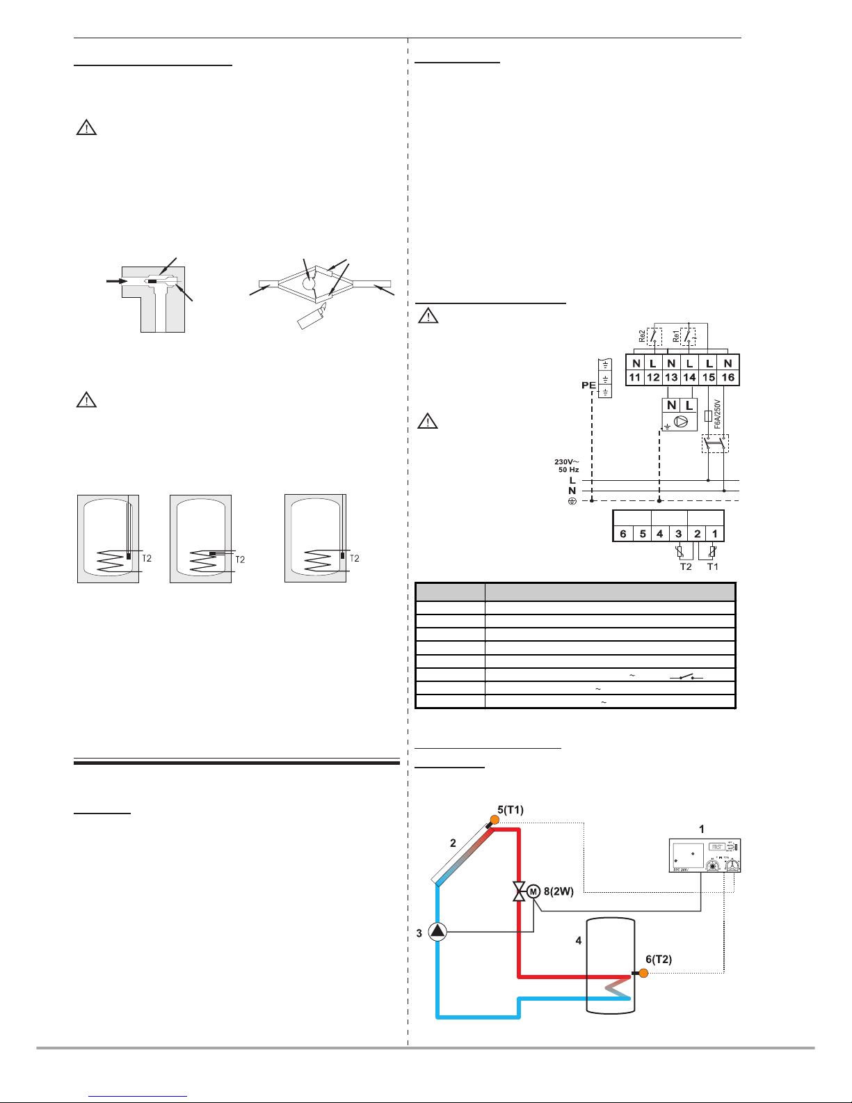
TERMINAL CONNECTION
1,2 sensorT1 – heating source (collector, boiler, …)
2,3 sensor T2 – hot water tank
11 N – not in use
12 L - not in use
13 N - neutral
14 L - phase - pump 6(1)A, 250V , 50Hz
15 L – phase mains 230V , 50Hz
16 N – neutral mains 230V , 50Hz
1.5 EXAMPLES OF USE
example: 1
Heating sanitary water with solar collectors.
6(1)A, 250V
Grounding wires should
be connected to special
terminal pins situated on
left side of terminal strips.
The thermostat is
designed for fixed
installation. When performing electric installation, an element should be
inserted which enables at
least 3 mm separation of
thermostat from the mains
(switch or socket). Prior to
each intervention in the
thermostat, first disconnect
it from the mains.
ELECTRIC CONNECTION
Before each intervention in the thermostat first discon-
nect the main power!
DTC 200/ (2 sensors)
1. Heating the domestic hot water from one heating source
(solar collectors, boilers, heat pump...) .
1.1 Basic
Differential thermostat controls the electric motor actuated ball
valve (EMV 110..) and the circulation pump.
The thermostat enables setting of two parameters:
1. Regulation of maximum temperature in hot water tank from
10° to 90°C.
This temperature is defined by T2 sensor witch is generally
mounted in upper third of heat exchanger.
2. Regulation of difference for exchanger from 0K to 15K.
With these regulation you define how much the value of the
source temperature (collector, boiler,...) should exceed the temperature of water around the exchanger in hot water tank, that
the thermostat opens the valve and activates the pump.
The difference is set in relation to the volume of heat losses of
the system which depend on lengths of pipelines from source
to hot water tank and on pipeline insulation.
SENSORS INSTALLATION
T1 AND T3 SENSORS INSTALLATION IN TO SOLAR
COLLECTOR OR BOILER:
Use KF sensors with silicon cable insulation (RED
colour)!
Install it as immersion sensor in collecting pipe at the top of the
collectors or boiler in provided sleeve. Connect sensors on the
terminals 1 and 2. Use sensors KF with red silicon cable and
use cable type J-Y (St) 1X 2X0,6 for connection.
For cables longer than 15m we recommend over-voltage protection with VDR resistor. For over voltage protection is recommended use of armoured cable and it must be earthed.
flow direction
T-piece 1/2”
pipe1/2”
VDR resistor
thermo-shrinkable
tubes
sensor kable
extension cable
T2 AND T4 SENSORS INSTALLATION IN DOMESTIC HOT WATER TANK (DHWT):
Use BSF1 sensors with PVC cable insulation (GRAY
colour)!
Install T2 sensor to provided place in hot water tank or on hot water
tank wall under isolation as contact sensor in upper part of exchanger. When sensor is mounted as contact one we recommend
to coat it with heat conducting paste or liquid metal. Use sensors
BSF1 with PVC cable.
In special purpose vertical or horizontal
tube (sensor should be protected against
accidental extraction).
On hot water tank with clip, wire and
spring strip (use paste for better heat
transmission).
WARNING!
At mounting protect sensors against ambient influence and
assure suitabile mechanical protection.
1.2 Operation
DTC 200 works as single differential thermostat, which measures the temperature of heating source (collectors, boiler, ...)
and in user (hot water tank).
Heating effect is provided, when heating source temperature is
higher than the temperature of the user (water in hot water
tank). Consequently minimum difference should be 3K-5K. Recommendable minimal value is 5K.
When the temperature of the source exceeds the temperature
around the user for pre-set difference opens the electric motor
actuated ball valve and switches the pump.
The thermostat switches off the pump if pre-set temperature is
reached in hot water tank (adjustable from 10° to 90°C).
Page 5
5
DTC 200
FIRŠT-ROTOTEHNIKA, s.p., Radegunda 54, SI-3330 Mozirje, Slovenija
tel. +386 3 898 35 00, fax. +386 3 898 35 35, e-mail: [email protected], http://www.rototehnika-sp.si
DTC 200 (3 sensors)
2. Heating the domestic hot water from one heating source
(solar collectors, boilers, heat pump...) in two water tanks - DTC
200/ (3 sensors).
2.1 Basic
In this case of use is DTC200 in function of double differential
thermostat. It is used for heating the domestic hot water in two
water tanks from one heating source. This is convenient in cases
when one water tank cannot accumulate whole energy from
solar collectors. At weakly sunny days is assured enough heated
water. Differential thermostat controls circulation pump and
changeover motor valve for diverting or two motorised ball valves
and two pumps for each water tank.
The thermostat enables setting two parameters:
1. Regulation of maximum temperature in hot water tanks from
10° to 90°C.
This temperature is defined by T2 and T4 sensors witch are
generally mounted in upper third of heat exchangers.
2. Regulation of temperature difference between heating source
(T1) and exchanger (T2) from 0K to 15K.
With these regulation you define how much the value of the
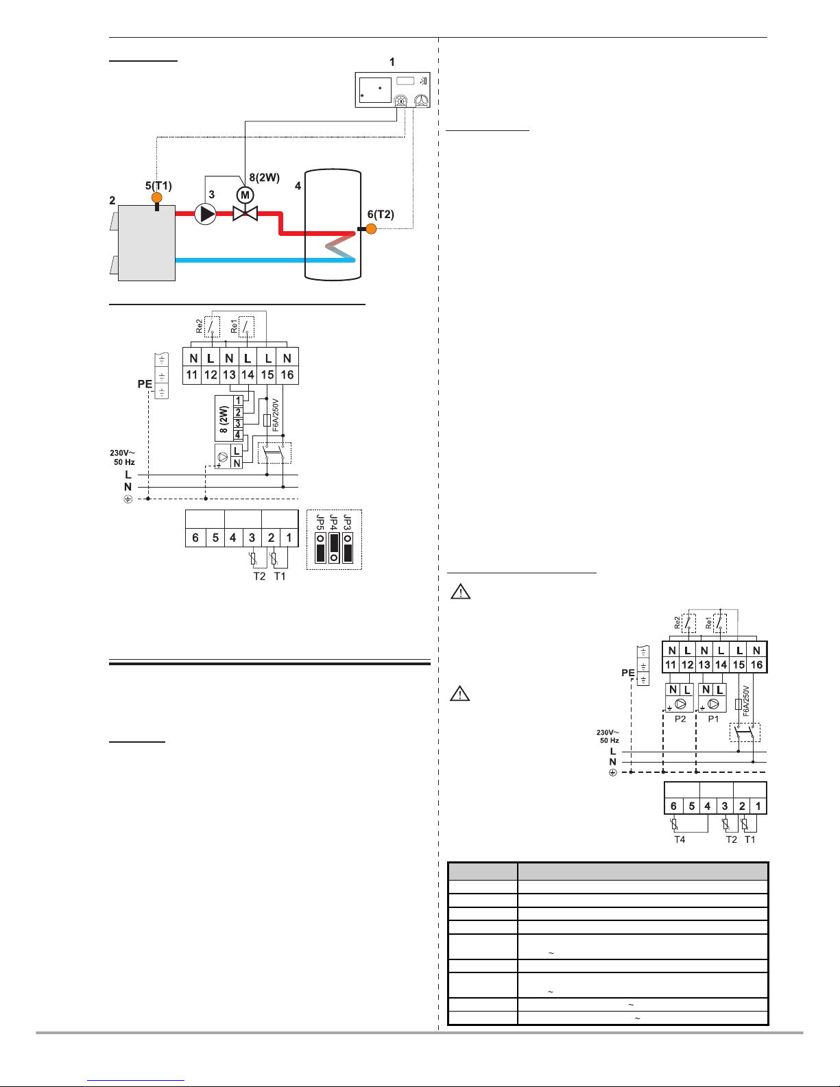
source temperature (collector, boiler,...) should exceed the temperature of water around the exchanger in hot water tank, that
Electric connection for examples 1 and 2
8 (2W) - Electric motor actuated ball valve
EMV 110..series 602, 502
6(1)A, 250V
Grounding wires should
be connected to special
terminal pins situated on
left side of terminal strips.
The thermostat is
designed for fixed
installation. When performing electric installation, an element should be
inserted which enables at
least 3 mm separation of
thermostat from the mains
(switch or socket). Prior to
each intervention in the
thermostat, first disconnect
it from the mains.
Before each intervention in the thermostat first discon-
nect the main power!
ELECTRIC CONNECTION
the thermostat opens the valve and activates the pump.
The difference is set in relation to the volume of heat losses of
the system which depend on lengths of pipelines from source
to hot water tank and on pipeline insulation.
2.2 Operation
DTC 200 double differential thermostat measures the temperature of heating source (collectors, boiler, ...) and in two users
(hot water tank).
One of users has priority. Usually is smaller water tank or upper
exchanger.
When the temperature is achieved, differential thermostat
changeover heating to second user - second water tank, lower
exchanger, swimming pool …
Differential makes changeover also in following cases:
1. Temperature of water in first water tank is achieved
2. Temperature of water in second water tank is lower than
preset temperature
When the temperature in both water tanks is achieved, the pump
is switch off.
The thermostat switches off the pump if pre-set temperature is
reached in both hot water tanks (adjustable from 10° to 90°C).
For this way of use you need three sensors (T1, T2 and T4). One
is mounted in solar collector other two in upper third of individual exchangers in hot water tanks.
Sensors T1 and T2 are designed for controlling first heating
circuit, which heats water in smaller water tank.
Sensors T1 and T4 are designed for controlling secondary heating circuit, which heats water in larger water tank or swimming
pool.
Sensor T1 is collector's sensor.
example: 2
Heating sanitary water with solid fuel boiler.
6(1)A, 250V
TERMINAL CONNECTION
1,2 sensorT1 – heating source (collector, boiler, …)
2,3 sensor T2 – primary hot water tank
4,6 sensor T4 – secondary hot water tank
11 N - neutral
12
L - phase – secondary heating circuit 6(1)A,
250V , 50Hz
13 N - neutral
14
L - phase – primary heating circuit 6(1)A,
250V , 50Hz
15 L – phase mains 230V , 50Hz
16 N – neutral mains 230V , 50Hz
Page 6
FIRŠT-ROTOTEHNIKA, s.p., Radegunda 54, SI-3330 Mozirje, Slovenija
tel. +386 3 898 35 00, fax. +386 3 898 35 35, e-mail: [email protected], http://www.rototehnika-sp.si
6
DTC 200
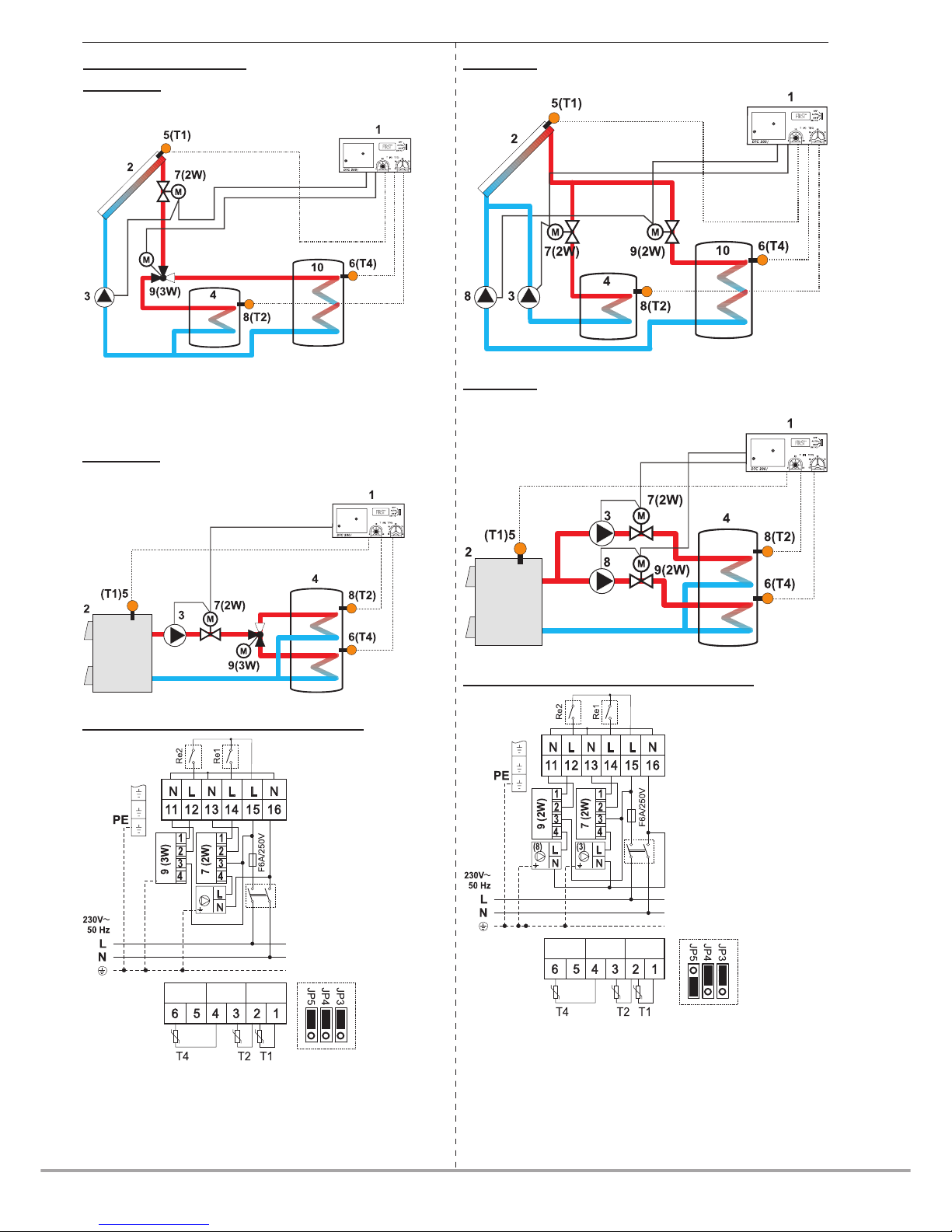
Electric connection for examples 5 and 6
7 (2W) - Electric motor actuated ball valve
EMV 110 series 602, 502
9 (2W) - Electric motor actuated ball valve
EMV 110 series 602, 502
Instead of the electric motor actuated ball valves 7 and 9 you
can use non-return valves. In this case connect pumps directly
on terminals 11-12 and 13-14.
6(1)A, 250V
example: 4
Heating sanitary water with solid fuel boiler into one hot water
tank with two exchangers.
Example 5
Heating hot water in two water tanks with solar collectors.
Example 6
Heating sanitary water with solid fuel boiler into one hot water
tank with two exchangers.
Electri connection for examples 3 and 4
7 (2W) - Electric motor actuated ball valve
EMV 110 series 602, 502
9 (3W) - Electric motor diverter valve
EMV 110 316
ROTODIVERT
Instead of the electric
motor actuated ball valve
you can use non-return
valve. In this case
connect pump directly on
terminals 13 and 14.
6(1)A, 250V
2.4 EXAMPLES OF USE
example: 3
Heating sanitary water with solar collectors into two hot water
tanks.
Acu. water tank
or swimming pool
Acu. water tank
or swimming pool
Page 7
7
DTC 200
FIRŠT-ROTOTEHNIKA, s.p., Radegunda 54, SI-3330 Mozirje, Slovenija
tel. +386 3 898 35 00, fax. +386 3 898 35 35, e-mail: [email protected], http://www.rototehnika-sp.si
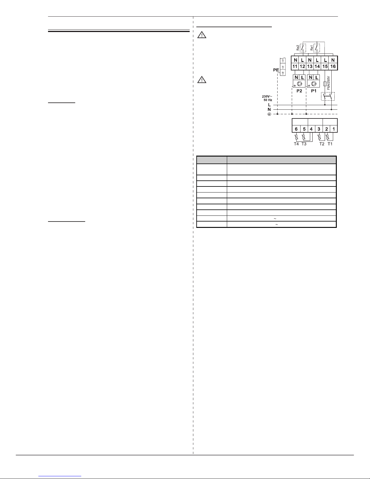
3.3 ELECTRIC CONNECTION
6(1)A, 250V
DTC 200 (4 sensors)
3. Heating the domestic hot water from two heating sources
(solar collectors, boilers, heat pump...) in one water tank - DTC
200 (4 sensors).
In this case of use is DTC200 in function of double differential
thermostat. It is used for heating the domestic hot water in one
water tanks from two heating sources (collector-boiler or collectors east-west). Differential thermostat controls motorised
ball valves and pump for each heating circuit.
3.1 Basics
The thermostat enables setting two parameters:
1. Regulation of maximum temperature in hot water tanks from
10° to 90°C.
This temperature is defined by T2 and T4 sensors witch are
generally mounted in upper third of heat exchangers.
2. Regulation of temperature difference between primary heating source (T1) and exchanger (T2) from 0K to 15K.
3. Regulation of temperature difference between secondary
heating source (T3) and exchanger (T4) from 0K to 15K.
With these regulations you define how much the value of the
source temperature (collector, boiler...) should exceed the temperature of water around the exchanger in hot water tank, that
the thermostat opens the valve and activates the pump.
The difference is set in relation to the volume of heat losses of
the system that depend on lengths of pipelines from source to
hot water tank and on pipeline insulation.
3.2 Operation
DTC 200 is double differential thermostat measures the temperature of two heating sources (collectors, boilers,…) and of
two spots in user (hot water tank). Heating effect is provided,
when heating unit(heating element in hot water tank) exceeds
the temperature of the user for set difference.
When the temperature of the source exceeds the temperature
around the exchanger for set difference, the thermostat opens
the valve (EMV110..) and activates the pump.
Thermostat closes the valve and switch of pump, when temperature difference is lower than pre-set value. Thermostat also
switches off a pump if pre-set temperature is reached in hot
water tank.
When pump operates for primary heating circuit (collectors),
operation of after-heating circuit is prevented. This assures
maximum energy savings during seasons and this also the
main role of solar systems.
For those applications you need four sensors. Two of them are
mounted into individual heating sources and two into upper
half of individual exchangers in hot water tank. T1 and T2 are
designed for primary (main) heating circuit which heats entire
quantity of water in hot water tank (lower exchanger), where T1
is a sensor of heating source (generally collectors) and T2 is a
sensor in lower part of hot water tank. T3 and T4 are designed
for additional, i.e. after-heating circuit which additionally heats
water in hot water tank (upper exchanger). T3 is a sensor of
heating source (generally boiler) and T4 is a sensor in upper
part of hot water tank.
Grounding wires should
be connected to special
terminal pins situated on
left side of terminal strips.
The thermostat is
designed for fixed
installation. When performing electric installation, an element should be
inserted which enables at
least 3 mm separation of
thermostat from the mains
(switch or socket). Prior to
each intervention in the
thermostat, first disconnect
it from the mains.
Before each intervention in the thermostat first discon-
nect the main power!
TERMINAL CONNECTION
1,2
sensorT1 – primary heating source (collector, solid
fuel boiler, …)
2,3 sensor T2 –hot water tank
4,5 Sensor T3 – secondary heating source (boiler,…)
4,6 sensor T4 – secondary hot water tank
11 N - neutral
12 L - phase – pump for primary circuit
13 N - neutral
14 L - phase – pump for secondary circuit
15 L – phase mains 230V , 50Hz
16 N – neutral mains 230V , 50Hz
Page 8
FIRŠT-ROTOTEHNIKA, s.p., Radegunda 54, SI-3330 Mozirje, Slovenija
tel. +386 3 898 35 00, fax. +386 3 898 35 35, e-mail: [email protected], http://www.rototehnika-sp.si
8
DTC 200
3.4 Examples of use
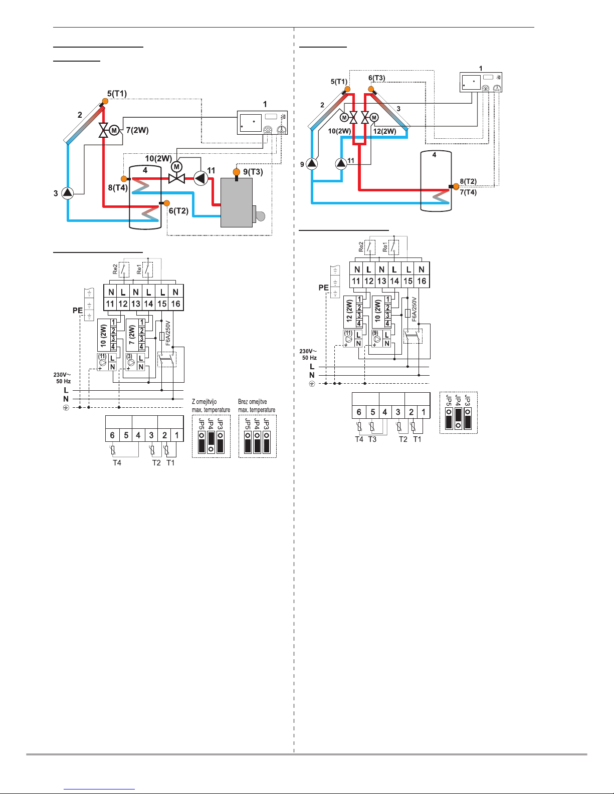
example 7
Heating sanitary water in one water tank with two exchangers
with solar collectors and boiler.
example 8
Heating sanitary water with collectors (east - west)
Electric connection:
10 (2W) - Electric motor actuated ball valve
EMV 110 series 602, 502
12 (2W) - Electric motor actuated ball valve
EMV 110 series 602, 502
Instead of the electric motor actuated ball valves 10 and 12 you
can use non-return valves. In this case connect pumps directly
on terminals 11-12 and 13-14.
6(1)A, 250VElectric connection:
7 (2W) - Electric motor actuated ball valve
EMV 110 series 602, 502
10 (2W) Electric motor actuated ball valve
EMV 110 series 602, 502
Instead of the electric motor actuated ball valves 7 and 10 you
can use non-return valves. In this case connect pumps directly
on terminals 11-12 and 13-14.
6(1)A, 250V
 Loading...