


®
®
Aquatherm
INSTALLATION AND APPLICATION MANUAL
FOR
AQUATHERM
COMBO HEATERS
®
FIRST CO. - P.O. BOX 270969 - DALLAS, TEXAS 75227 - Ph. (214) 388-5751 - Fax (214) 388-2255 - www.firstco.com
1

Page
Introduction 3
Table of Contents
Sequence of Operation
General Description:
Air handler cabinet 3
Heating and cooling coils 3
Add-on hot water coil 3
Circulating pump 3
Flow control module 3
Check valve 3
Air purge valve 4
Blower door safety switch 4
Water heater 4
Boiler 4
Accessories:
Thermostat 4
Freeze protector 4
Equipment Sizing:
Condensing unit 4
Air handler 4
Water heater 5
3
Installation:
Duct work 5
Electrical 5
Water piping 6
1. Material 6
2. Solder connections 6
3. Insulation 6
4. Length 6
5. Shut-off valves 6
6. Piping connections 6,8-10
Air handler 6
Flow control module 6
Water heater 6
Multiple water heaters 7
Anti-scald valve 7
Start-up Procedure (heating cycle)
Troubleshooting 12
7
2

The Aquatherm® is a First Co. air handler that
converts a properly sized gas or oil-fired water heater
into a highly efficient, dual - purpose appliance that
can heat your home as well as provide hot water for
domestic purposes.
Any properly sized water heater (for heating) and
split system type condensing unit (for cooling) will
work with First Co. Aquatherm® air handlers and
are to be supplied by others. NO SPECIAL WATER
HEATER IS REQUIRED!
Aquatherm® air handlers are even compatible
with boiler systems.
Aquatherm® air handlers include a fan motor for
air circulation, hot water circulating pump, hot water
heating coil, air purge valve, check valve, components for low voltage control and most include a
cooling coil for air conditioning. All components in the
water piping meet NSF61 and/or california AB1953
requirements.
SEQUENCE OF OPERATION
(Heating mode)
When space heating is needed, the wall thermostat
energizes a small pump which circulates hot water
(135 to 140 degrees ) from the water heater to the hot
water coil in the air handler. As the fan motor forces
the cool return air from the home over the hot water
coil, the air absorbs heat from the hot water and this
warm air (about 105 to 110 degrees) is then circulated
throughout the duct system and into the home.
IMPORTANT. . . . . in most applications the water will
lose only 15 to 25 degrees in temperature while circulating through the hot water coil and will RETURN
to the water heater at about 115 to 125 degrees to
be reheated.
Add - on hot water coil: First Co. HWC series add-on
hot water coils are designed to be installed in either
existing or new duct work and operate in conjunction
with the existing fan motor to provide complete or
supplemental space heating from a gas or oil - fired
water heater. These coils are completely cased and
utilize the separate “flow control module” which can
be installed at the water heater for easy access and
service (see “flow control module”).
Circulating pump: All circulating pumps circulate
water at a rate of 3 to 6 gallons per minute and are
either factory installed or included as part of the field
installed “flow control module”. These pumps are
designed to circulate a precise amount of hot water
between the water heater and air handler or add - on
coil.
Flow control module: This U.L. Listed device con
sists of the circulating pump, check valve, air purge
valve, 6' plug - in line cord and pump relay. The
module is sold & shipped separately with HWC add
- on hot water coils. The module can be field installed
anywhere in the hot water heating loop between the
water heater and hot water coil and offers the advantage of being able to install the pump assembly in
the most appropriate location for service and maintenance. Modules must be installed with the motor
in a horizontal position. Junction box should not be
located underneath the pump.
FLOW CONTROL MODULE - WIRING DIAGRAM
-
GENERAL DESCRIPTION
Air handler cabinet: Air handlers with cabinets are
made of galvanized steel and fully insulated to reduce
noise and maximize efficiency. Throwaway filters are
factory installed in most air handlers.
Heating and cooling coils: All heating and cooling
coils are made of copper tubes with mechanically
bonded aluminum fins for maximum heat transfer.
Manual air vents are included on all hot water coils.
Cooling coils have either piston - type metering de
vices or field installed expansion valves. Primary
and secondary condensate drain connections are
provided on each cooling coil. All primary connections
are 3/4 inch MPT.
-
Check valve: A check valve is factory installed in
the hot water loop to eliminate any thermosyphoning
(hot water circulating through the heating coil) while
operating in the cooling mode. The check valve is
installed within the air handler or as part of the “flow
3

control module”.
Air purge valve: All air handlers and / or “flow control
modules” include a large manual air purge valve to
facilitate air removal from the heating loop prior to
system start - up. When the air handler and water
heater are piped according to First Co. instructions,
the air in the hot water coil and piping will only need
to be removed before initial start - up or after air has
gotten into the system because of a plumbing leak
or break in a water main. This can be accomplished
by using the 2 - step process described under “start
-up procedure”.
Blower delay relay: FWA-HW,HBXB-HW,HBQB,UCHW and UCQB series air handlers include a blower
delay relay that allows the circulating pump to operate
on a call for heat for 20 to 45 seconds
motor comes on to deliver warm air quicker when the
heating system starts. This relay also keeps the fan
motor on for 20 to 45 seconds after the thermostat
is satisfied in the heating cycle to maximize the efficiency of the heating coil.
before the fan
All other air handlers require a 24 volt thermostat
that energizes the fan motor on a requirement for cool
ing and heating. This is commonly called an "electric
heat" thermostat. CAUTION . . . . . a gas furnace
thermostat will NOT work with these units because
the fan motor will not come on when the thermostat
calls for heat.
Normal heat anticipator setting should be 0.3 to 0.4.
If a set-back thermostat is used, allow extra time for
recovery in the morning.
Freeze protector: Kit number 941-1 can be field
installed on any Aquatherm® air handler or add -on
coil and is highly recommended when the air handler
or hot water coil is installed in a space that may be
subjected to freezing temperatures such as in an attic
or crawl space. The sensor attaches to the hot water
coil and is wired to R and W in the low voltage circuit.
If for any reason the temperature of the hot water coil
falls below 38 degrees the sensor will bring on the
pump to circulate hot water. This will occur even if
the thermostat is in the "off" position.
-
Flue gas safety switch: All "Q" type air handlers,
as well as FWA-xx series air handlers, include a
factory installed flue gas safety switch (except 5 ton
models). When the blower door is removed for any
reason the air handler fan motor will not operate.
This is especially important when the water heater
is in the same closet as the air handler because
products of combustion from the water heater flue
pipe could be circulated throughout the duct system
if the air handler were allowed to operate without the
door in place.
Water Heater: Any properly sized gas or oil - fired
water heater will work ( even direct vent or powered
vent types ). Electric water heaters are not recom
mended because of their slow recovery rate. Water
heater warranties are not affected by this system
since no modification of the water heater is necessary.
Selection of higher efficiency water heaters will result
in even greater savings.
Boiler: Most First Co.
and add - on hot water coils are also compatible with
boilers and instantaneous water heaters. Please contact the factory for assistance in selecting the proper
equipment for these applications. (See Page 10 for
wiring diagram of multiple air handlers.)
Aquatherm® air handlers
EQUIPMENT SIZING
Condensing unit: The condensing unit should be
sized to meet the calculated heat gain according to
an approved heat gain formula.
Air handler: Select an air handler with a heating
BTUH that exceeds the structure's calculated heat
loss and a cooling coil matched to the tonnage size
of the outdoor condensing unit.
Special note . . . . . the actual heating output of the
air handler (BTUH) will not be greater than the heating
output of the water heater (water heater BTUH input
multiplied by it's recovery efficiency) regardless of the
listed heating BTUH of the air handler.
-
ACCESSORIES
Thermostat: All "Q" type air handlers will operate
with any standard 24 volt heat / cool or heat pump
thermostat.
Water heater: Add 10 to 20% to the structure's heat
loss to obtain the minimum output of the required
water heater (output = input x recovery efficiency).
A minimum 40 gallon high recovery and / or high efficiency gas or oil-fired water heater is recommended.
In addition to the above formula, the following vol-
4

ume sizing guide is satisfactory in most parts of the
country: (minimum requirements)
1.5 and 2 ton air handlers = minimum 40 gallon
2.5 and 3 ton air handlers = minimum 50 gallon
3.5 and 4 ton air handlers = either two 40 gallon water heaters piped together, one high input (63,000 to
75,000 BTUH) 50 gallon or one 72 to 75 gallon.
5.0 ton air handlers = multiple water heaters or boiler
with at least 105,000 BTUH output.
For additional assistance in water heater sizing,
contact the factory or a qualified profession engineer.
INSTALLATION
The installer must adhere strictly to all local and
national code requirements pertaining to the installation of this equipment.
Detailed installation instructions are shipped with
each component of the system and should also be
followed in detail.
Duct work: The return air duct must have the same
free area as the opening provided on the air handler.
If there is no ducted return, applicable installation
codes may limit the unit to installation only in a single
story residence.
Electrical: Units are provided with wiring diagrams
and nameplate data to provide information required
for necessary field wiring. Knockouts are provided in
the cabinet for connection of power supply. See “ac
cessories” for thermostat information. All air handlers
operate on 115 volt - 1phase - 60 cycle line voltage
and 24 volt control.
-
5
(See figures 3, 4, 5, 14 and 15 for typical wiring
diagrams.)
Water piping:
1. Material: It is recommended that all piping be-
tween the water heater and hot water coil be
3/4 inch nominal (7/8 O.D.) copper except the
60HBQB and 60HBXB-HW is 1" nominal (1-1/8"O.
D.). Other material approved for potable hot water
systems may also be used if approved by local
code authorities.
2. Solder connections: All copper joints in the water
lines must be made with low temperature, non
lead solder!
3. Insulation: It is recommended that all piping
be adequately insulated to prevent freezing and
“freeze protector” ( see “accessories” ) be installed
on the hot water coil to prevent freezing when
piping is run in a space subjected to freezing
temperatures.
4. Length: Piping should not exceed 200 total feet of
length. Air handlers should not be installed more
than 40 feet above the water heater.
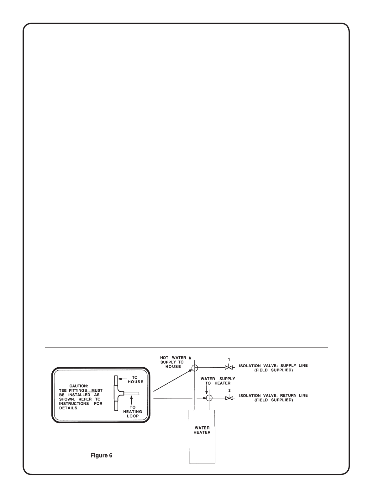
5. Shut - off valves: In addition to the main cold
water valve supplying the water heater, it is recommended that one shut - off valve be installed
on the hot water supply line to the air handler and
one on the return line from the air handler (or hot
water coil). These valves will facilitate air purging
during start - up ( see “start - up” ) and allow unit
isolation for repair.
6. Piping connections: On all cased type air handlers the water inlet or “supply” connection to the
hot water coil is the one on the right as you face
the the air handler and will be marked accordingly.
Air handlers with internally installed circulating
pumps will not circulate water if piped backwards. Water lines to and from the air handler
must be connected to the horizontal connection
of the “T” fittings in the vertical hot and cold water
supply lines at the water heater. (See figure 6).
This insures that any air in the water heater will
bypass the heating loop and then be purged each
time hot water is used in the dwelling. If this piping procedure is not followed the pump may “air
lock” and fail to pump hot water. Any other piping
procedure must address the elimination of air in
the heating loop. See figures 8 through 9 for approved piping variations. Contact the factory for
assistance with alternate piping procedures.
Air handler: Holes should
handler or coil cabinets (except through duct flanges)
since damage to the coils could result. Multiple air
handlers may be installed on one water heater provided the water heater and piping are sized properly.
Piping should be similar to that required for individual
air handler.
Flow control module (if required): The flow control
module can be installed anywhere in the hot water
loop to or from the air handler (between the water
heater and air handler). Modules must be installed
with the motor in a horizontal position. Junction box
should not be installed underneath the pump. Water
should flow from the outlet (hot) side of the water
heater to the air handler and then back to the supply
(cold ) side of the water heater. Arrow on bottom of
pump indicates the direction of flow when pump is
energized. The module is furnished with a 6 foot cord
and plug for convenient connection to a wall outlet.
For those areas where local codes require “hard”
wiring, discard the cord assembly and wire directly to
the connections within the 4 x 4 box using acceptable
wiring materials.
Water heater: Water heaters should be installed ac
cording to the manufacturer’s installation instructions.
If a “back flow preventer” is required by code,
the T & P valve on the water heater may tend to
drip water because of pressure build-up in the water
not be drilled into the air
-
6

heater. This problem is a direct result of the back
flow preventer . . . . . not the heating system. An
expansion tank may need to be installed to solve this
problem. Most water heaters are now labeled with
this information.
Multiple water heaters: When sizing requirements
call for more than one water heater per air handler,
water heaters may be connected together according
to the water heater manufacturer’s instructions. (See
figure 10 page 9)
Anti-scald valve: A water heater is designed to
produce hot water. Hot water represents a serious
safety hazard due to the potential of scalding. The
temperature of water normally required to provide
space heating (135 to 140 degrees) may be hotter
than certain codes allow for domestic hot water. An
“anti-scald valve” can be installed in the hot water
piping that would allow the domestic water to be sup
plied at a lower temperature than the space heating
water. These can be obtained locally and should be
installed according to the manufacturer’s installation
instructions. (See figure 12)
START - UP PROCEDURE
(Heating cycle)
1. Open the main shut - off valve to the water heater
and the two shut - off valves to and from the air
handler or hot water coil.
2. Fill the water heater. Open a hot water faucet
somewhere in the house while filling the water
heater in order to vent the air. When the tank is
full and all the air is purged, close the faucet.
3. Ignite the water heater according to the manufacturer’s instructions and allow it to come up to
temperature (about 45 minutes). DO NOT IGNITE
THE WATER HEATER WITHOUT WATER IN
THE TANK!
4. Purge the air handler’s hot water coil and lines: The
following procedure allows the use of city water
pressure to purge the air handler hot water coil and
lines even when the air handler is located higher
than the water heater. Once the air is completely
removed upon start - up, the circulating pump
will circulate the required amount of hot water
through the heating loop.
Note: It may require purging several gallons of water
so either have a bucket available or connect a garden hose to the purge valve and route to a drain.
Close valve number 2 and open valve number 3
(See figure 7). Next , open the air purge valve
located either on the flow control module or inside
the air handler. When all the air is purged, close
valve number 3 and open valve number 2. When
all the air is purged, open both valves and close
the air purge valve.
-
5. On Grundfos pumps, vent the air from the pump
chamber by loosening the large screw plug on
top of the pump motor until water appears. Then
retighten the plug.
6. Switch the room thermostat to “heat” and set it high
enough to energize the fan motor and pump. It
may be necessary to “feel” the pump to determine
if it is operating. If the pump is operating properly
and the water temperature in the water heater has
reached the set point, the hot water line going into
the air handler will begin to get hot. If the pump
is running but hot water is not circulating, refer to
"troubleshooting”.
7. Adjust the water heater thermostat so that the water
entering the hot water coil is 135 to 140 degrees
with the system energized and operating long
enough for all temperatures to stabilize.
7

Conventional Piping Diagram
Side Tap (4 Pipe) Water Heater Piping
FIGURE 8
FIGURE 9
8
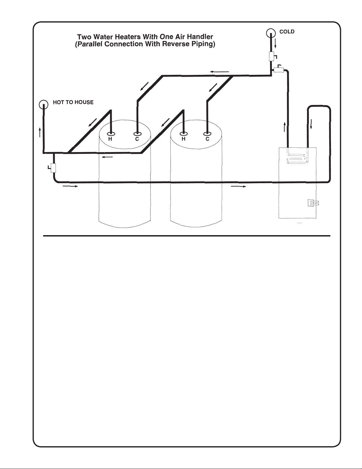
FIGURE 10
9
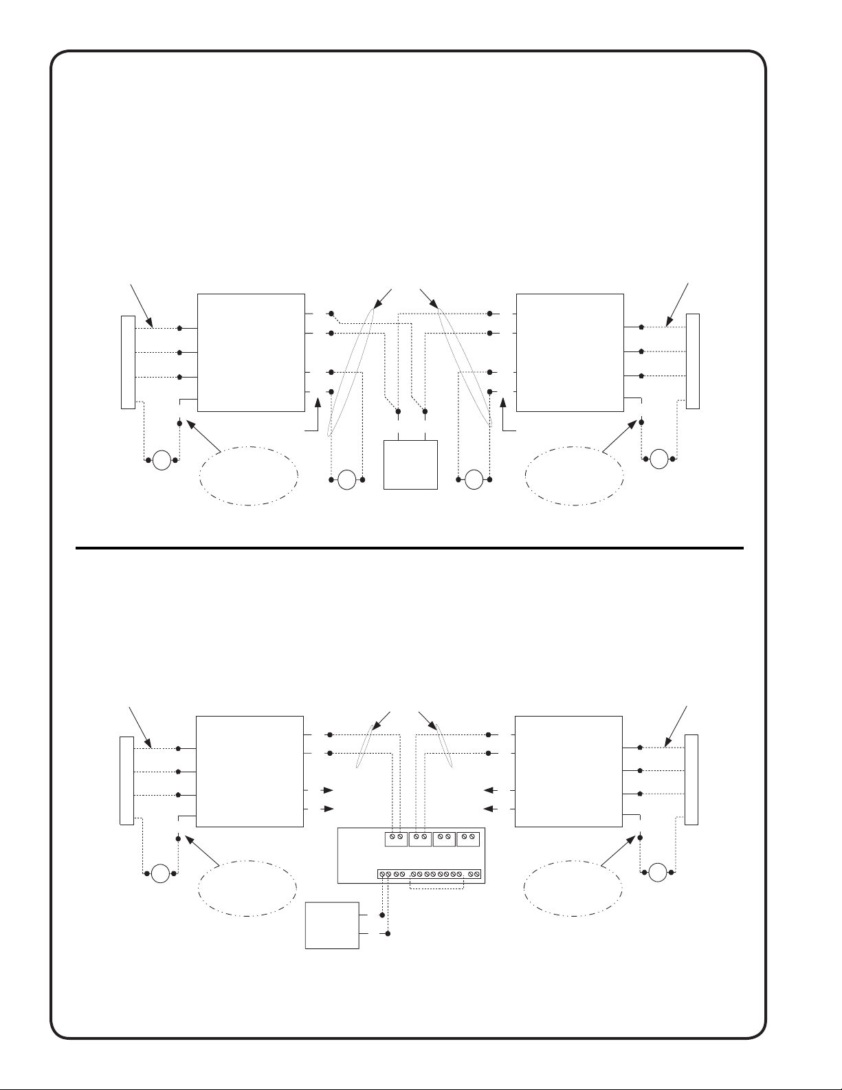
Zone Valves Install a motorized valve with each air handler to control flow to that zone as
BOILER
CLASS 2 WIRING
24 VOLT
CLASS 2 WIRING
24 VOLT
CLASS 2 WIRING
CONDENSER
CONTACTOR
CONDENSER
CONTACTOR
24V REMOTE
THERMOSTAT
24V REMOTE
THERMOSTAT
NOTE: CAP OFF
BROWN IF NO
CONDENSING UNIT
IS USED
NOTE: CAP OFF
BROWN IF NO
CONDENSING UNIT
IS USED
TACO
SR 504
SWITCHING
RELAY
ZONE 1
ZONE 3
ZONE 2
ZONE 4
X
X
120V CIRCULATOR
CONNECTIONS
T
T
G
W
R
Y
HBXB-HW
FAN COIL
24V
T
T
24V
BRN
HBXB-HW
FAN COIL
G
W
R
C
G
W
R
Y
24V
T
T
24V
BRN
G
W
R
C
MV
MV
BOILER
T
T
4 CONDUCTOR
CLASS 2 WIRING
24 VOLT
CLASS 2 WIRING
24 VOLT
CLASS 2 WIRING
PIGTAIL LEADS FOR
MOTORIZED VALVE
PIGTAIL LEADS FO
R
MOTORIZED VALVE
24V MOTORIZED
ZONE VALVE
24V MOTORIZED
ZONE VALVE
CONDENSER
CONTACTOR
CONDENSER
CONTACTOR
24V REMOTE
THERMOSTAT
24V REMOTE
THERMOSTAT
NOTE: CAP OFF
BROWN IF NO
CONDENSING UNIT
IS USED
NOTE: CAP OFF
BROWN IF NO
CONDENSING UNIT
IS USED
G
W
R
Y
HBXB-HW
FAN COIL
G
W
R
C
24V
T
T
24V
BRN
HBXB-HW
FAN COIL
G
W
R
C
G
W
R
Y
24V
T
T
24V
BRN
required.
FIGURE 11
TYPICAL WIRING SCHEMATIC
FOR MULTIPLE ZONE CONNECTIONS
WITH ZONE VALVES
TYPICAL WIRING SCHEMATIC
FOR MULTIPLE ZONE CONNECTIONS TO
TACO SR-504/506 SWITCHING RELAY
10

TROUBLESHOOTING
(Most likely problems and cause)
Important: For system to operate properly power
should be turned ON and all shut - off valves should
be OPEN.
Pump does not run: These pumps may sometimes
“stick” due to non - use and fail to start. Before replacing
pump:
1. Turn off power. On Grundfos pumps remove large
screw plug in end of pump motor and turn shaft several times with a small screwdriver. Replace plug and
start system. Pump should start.
2. If pump has to be replaced, first shut off all isolation
valves between the water heater and air handler
and relieve the city water pressure by opening the
air purge valve. Then remove the four screws that
attach the pump motor to the pump volute rather than
un-soldering the entire pump assembly.
Fan motor runs on cooling but not on heating:
Thermostat is wrong type (a gas furnace type ther-
mostat will not bring on the fan motor in the heating
cycle on certain air handlers). For correct type of
thermostat, see “accessories”.
Note: FWA-HW air handler has a blower delay.
Pump is noisy:
Air may still be in the heating loop. Re-purge the
system as described under “start - up procedure".
Water heater T & P valve “weeping”:
This situation usually occurs in those systems located
in areas where local codes require the installation of
a “backflow preventer” in the cold water supply line
to the water heater. This situation is caused by the
expansion of the water when heated. An expansion
tank may be required to solve this problem. Contact
local plumbing authorities for assistance.
Insufficient or no heat:
1. Air still in heating loop. Re-purge system.
2. Inlet and oulet piping connections at the air handler
may be piped backwards. (See "Piping connections").
3. Water heater thermostat not turned up high
enough.
4. Water heater thermostat not calibrated properly.
5. Restricted or improperly installed dip tube in water
heater.
6. Restriction somewhere in heating loop. Confirm
that no other check valves or devices have been
installed in the heating loop except as supplied by
First Co.
Note: Some water heaters come with a normally
closed spring-loaded check valve factory installed
on one of the space heating connections. Since
the circulating pump in the Aquatherm® system
may not be able to open this valve in addition to
the Aquatherm® check valve, this valve should
be removed before installation.
7. Air handler or hot water coil not large enough.
8. Water heater not large enough.
Hot water circulates through hot water coil during
cooling cycle:
1. Check valve may be stuck open allowing "thermosyphoning" (circulation) of hot water. This occurs
when the hot water pipes are not capped-off during installation, allowing foreign debris such as
solder, insulation, and other building materials to
enter the piping. If not completely purged from the
system, this "debris" can lodge under the check
valve seat and allow hot water to flow through the
hot water coil even in the summer. To solve this
problem, flush the heating loop several times as
indicated in the "start-up procedure" on Page 7.
note: Check valve in models made after year 1999
are located in the pump itself.
CONCLUSION
Always leave the appropriate literature and / or
manual with the homeowner and whenever possible
take the time to explain the operation and advantages
of the system.
11
All technical specifications subject
to change without notice.

Catalog No. IAM1010 (Replaces IAM309)
12
 Loading...