

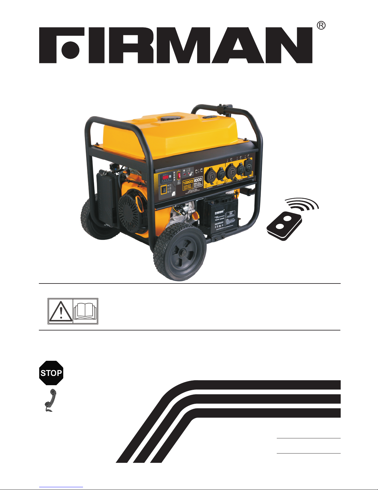
Firman P08003, P05701, PO3603, P03612 Owner's Manual
P/N:380745452 Rev:00
OWNER’S MANUAL
Read all safety precautions and instructions carefully
before operating equipment.
Ensure engine is stopped and level before performing
any maintenance or service.
IMPORTANT:
Record product information to reference when ordering parts or
obtaining warranty coverage.
Serial Number:
PORTABLE GENERATOR
MODEL NUMBER
P 0 8 0 0 3
Rev Level:00
DO NOT RETURN TO
STORE!
CALL US FIRST!
CUSTOMER HOTLINE
1-844-347-6261
FOR QUESTIONS OR SERVICE
INFORMATION
Purchase Date:

Table of Contents
. . . . . . . . . . . . . . . . . . . . . . . . . . . .1
Safety Precautions . . . . . . . . . . . . . . . . . . . . .2
Unpacking the Generator. . . . . . . . . . . . . . . .6
Parts Included. . . . . . . . . . . . . . . . . . . . . . . .6
Assembly . . . . . . . . . . . . . .. . . . . . . . . . . . . . . 7
Install the Wheel Kit . . . . . . . . . . . . . . . . . . 7
Install the Support Leg. . . . . . . . . . . . . . . . 7
Install the Handle. . . . . .. . . . . . . . . . . . . . . 7
. . . . . . . . . . . . . .8
Controls and Features. . . . . . . . . . . . . . . . . 9
Generator. . . . . . . . . . . . .. . . . . . . . . . . . . .9
Control Panel. . . . . . . . . . . . . . . . . . . . . . . 10
Remote Start. . . . . . . . . . . . . . . . . . . . . . . 11
Remote Control Programming . . . . . . . . 12
Specifications. . . . . . . . . . . . . . . . . . . . . . . . 13
Add Engine Oil . . . . . . . . . . . . . . . . . . . . . .14
Low Oil Shutdown . . . . . . . . . . . . . . . . . . .14
Add Fuel . . . . . . . . . . . . . . . . . . . . . . . . . . . 15
Operation at High Altitude . . . . . . . . . . .15
Grounding. . . . .. . . . . . . . . . . . . . . .. . . . . .16
System.. . . . . . . . . . . . . . . . . . . . . . .. . . . . .16
Operation . . . . . . . . . . . . . . . . . . . . . . . . .. . . . 17
Generator Location . . . . . . . . . . . . . . . . . . 17
Surge Protection . . . . . . . . . . . . .. . . . . . . .17
Starting the Generator (Recoil Start) . . 18
Starting the Generator (Electric Start) .. 19
Starting the Generator (Remote Start) . 20
Connecting Electrical Loads . . . . . . . .. . . 21
Stopping the Engine . . . . . . . . . . . . . . . . . 21
Low Oil Shutdown . . . . . . . . . . . . . . . . . . 22
Do Not Overload Generator . . . . . . . . . . . 22
Introduction
Battery Cable Connection
Connecting to a Building’s Electrical
Maintenance And Storage. . . . . . . . . . . . . . 23
Maintenance Schedule . . . . . . . . . . . . . 23
Engine Maintenance .. . . . . . . . . . . .. . . . 24
Change Engine Oil . . .. . . . . . . . . . . . . . 24
Air Filter Maintenance. . . . . . . . . . . . . .24
Spark Plug Maintenance. . . . . . . . . . . . 25
Cleaning Fuel Strainer . . . . . . . . . . . . 25
. . . 25
Generator Maintenance . . . . . . . . . . . . . . 26
. . . . . . . . . . . . . . . 26
Service and Storage . . . . . . . . . . . . . . . .. 27
Trouble Shooting . . . . . . . . . . . . . . . . . . . . .28
Parts Diagram and Parts List . . . . . . . . . . 29
Generator Parts Diagram . . . . . . . . . . . . 29
Engine Parts Diagram . . . . . . . . . .. . . . . 30
Parts List . . . . . . . . . . . . . . . . . . . . . . . . . 31
Service Information . . . . . . . . . . . . . .. . . . . 33
Warranty. . . . . . . . . . . . . . . . . . . . . . . . . . . . . 33
Inspect Muffler and Spark Arrester
Battery Replacement
English Customer Service: 1-844-FIRMAN1

Thank you for purchasing a FIRMAN generator.
This manual covers operation and maintenance of the FIRMAN generators. All information in this
publication is based on the latest production information available at the time of approval for printing.
The manufacturer reserves the right to change, alter or other wise improve the generator and this
documentation at any time without prior change.
Page 01
This manual contains safety information to make you aware of the hazards and risks associated
with generator products and how to avoid them. This generator is designed and intended only
for supplying electrical power for operating compatible electrical lighting, appliances, tools and
motor loads, and is not intended for any other purpose. It is important that you read and
understand these instructions thoroughly before attempting to start or operate this equipment.
Save these original instructions for future reference.
Important Safety Information
The manufacturer cannot possibly anticipate every possible circumstance that might involve a
hazard. The warnings in this manual and the tags and decals affixed to the unit are therefore not
all-inclusive. If you use a procedure, work method or operating technique that the manufacturer
does not specifically recommend you must satisfy yourself that it is safe for you and others. You
must also make sure that the procedure work method or operating technique that you choose
does not render the generator unsafe.
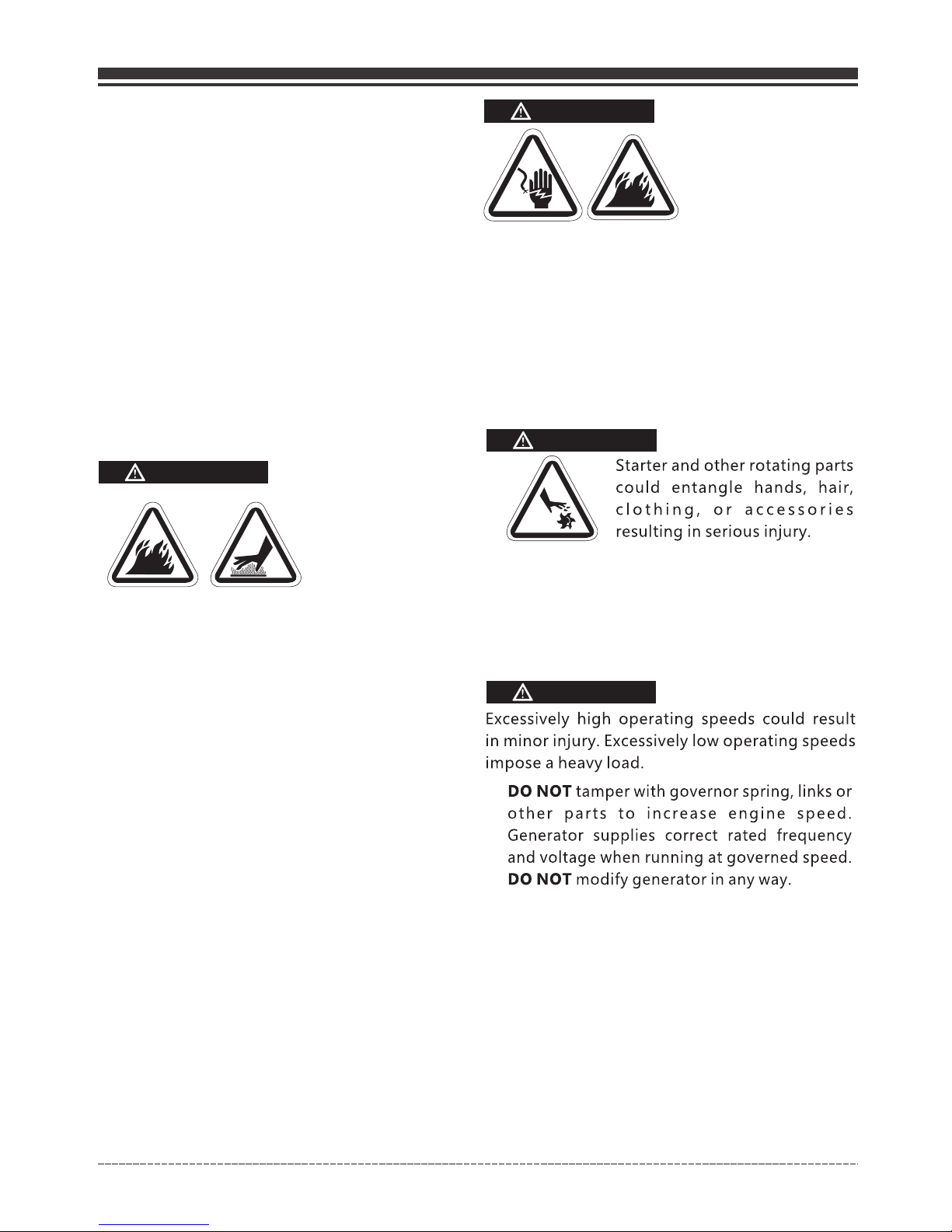
SAFETY INFORMATION
DANGER WARNING CAUTION
DANGER indicates a
potentially hazardous
situation which, if not
avoided. WILL result in
death or serious injury.
WARNING indicates a
potentially hazardous
situation which, if not
avoided, could result in
death or serious injury.
CAUTION indicates a
potentially hazardous
situation which, if not
avoided, may result in minor
or moderate personal injury,
or property damage.
Toxic Fumes
Fire Hazard
Hot Surface.
Do Not Touch the Surface.
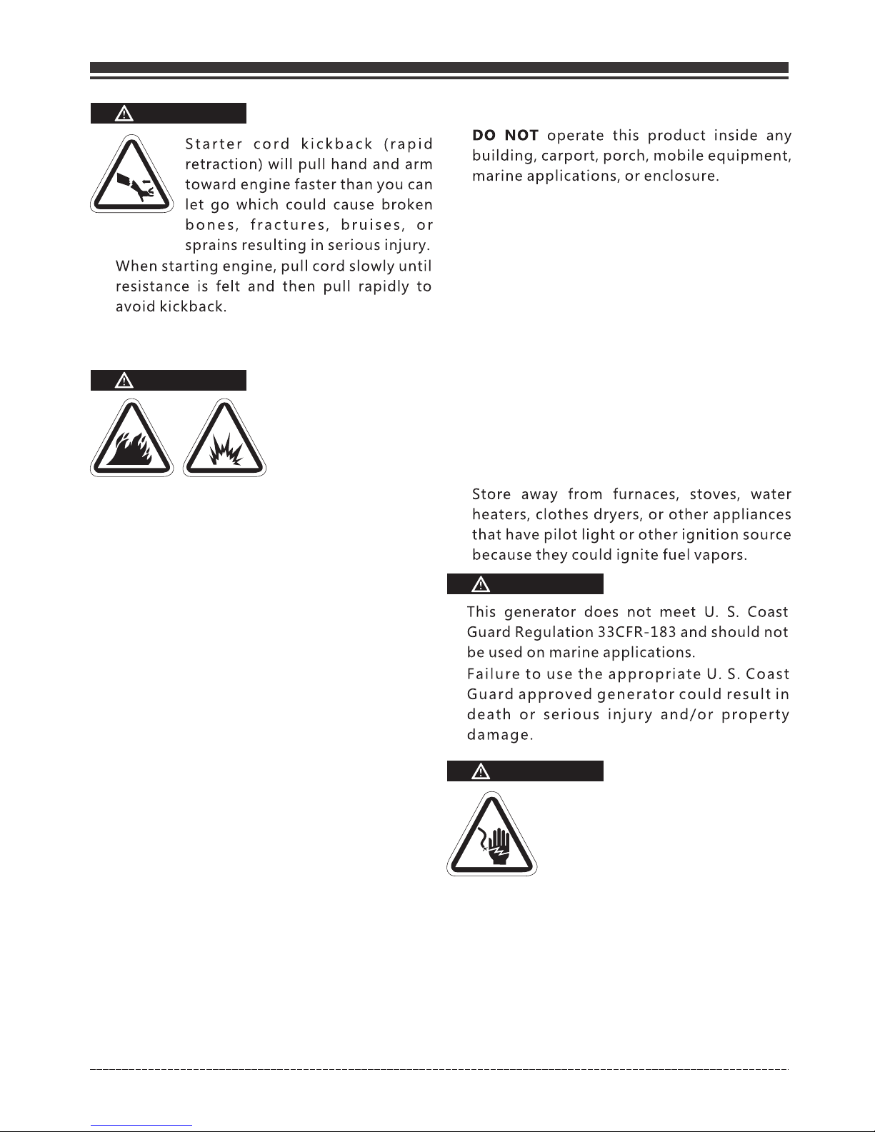
Kickback
Risk of Electric Shock
Explosion Hazard
Rotating Parts Entanglement
Hazard
Operator’s Manual
INTRODUCTION
English Customer Service: 1-844-FIRMAN1
SAFETY PRECAUTIONS
Page 02
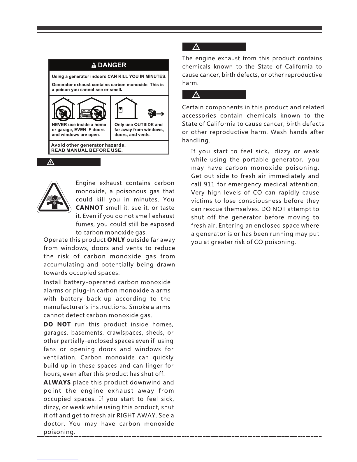
WARNING
POISONOUS GAS HAZARD.
•
•
•
•
WARNING
WARNING
•
English Customer Service: 1-844-FIRMAN1
Page 03
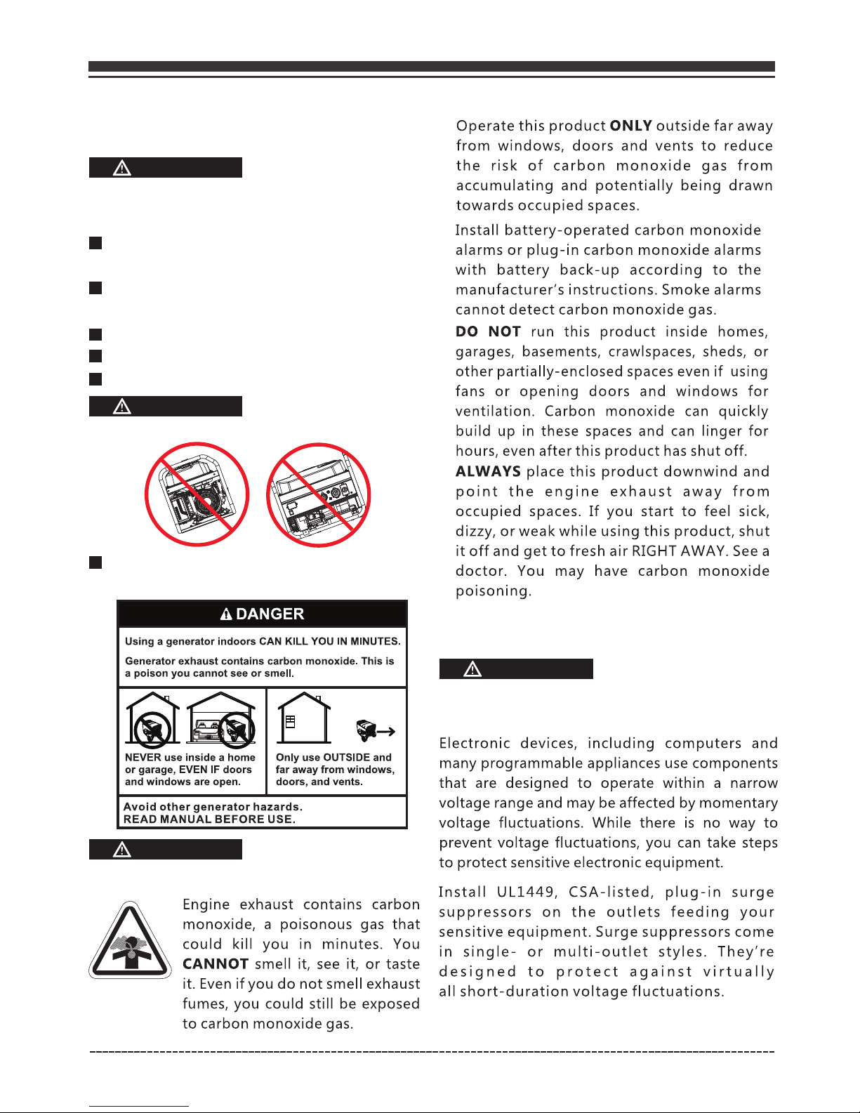
CORRECT USAGE
Example location to reduce risk of carbon monoxide poisoning
•
ONLY use outside and downwind, far away from windows, doors and vents.
•
Direct exhaust away from occupied spaces.
INCORRECT USAGE
Do not operate in any of the following locations:
Near any door, window or vent
Garage
Basement
Crawl Space
Living Area
Attic
Entry Way
Porch
Mudroom
English Customer Service: 1-844-FIRMAN1
Page 04
WHEN OPERATING EQUIPMENT
•
DO NOT tip engine or equipment at angle
which causes fuel to spill.
DO NOT stop engine by moving choke
control to “Start” position.
•
•
WHEN TRANSPORTING, MOVING
OR REPAIRING EQUIPMENT
Transport/move/repair with fuel tank
EMPTY or with fuel shutoff valve OFF.
•
•
DO NOT tip engine or equipment at angle
which causes fuel to spill.
Disconnect spark plug wire.
•
WHEN STORING FUEL OR EQUIPMENT
WITH FUEL IN TANK
•
WARNING
•
•
WARNING
Generator voltage could cause
electrical shock or burn resulting
in death or serious injury.
•
WARNING
•
•
NEVER start or stop engine with electrical
devices plugged in and turned on.
WARNING
Fuel and its vapors are extremely flammable
and explosive which could cause burns, fire,
or explosion resulting in death or serious
injury and/or property damage.
WHEN ADDING OR DRAINING FUEL
Turn generator engine OFF and let it cool at
least 2 minutes before removing fuel cap.
Loosen cap slowly to relieve pressure in tank.
Fill or drain fuel tank outdoors.
•
•
DO NOT overfill tank. Allow space for fuel
expansion.
If fuel spills, wait until it evaporates before
starting engine.
•
Keep fuel away from sparks, open flames,
pilot lights, heat, and other ignition sources.
Check fuel lines, tank, cap, and fittings
frequently for cracks or leaks. Replace if
necessary.
DO NOT light a cigarette or smoke.
•
•
•
•
WHEN STARTING EQUIPMENT
Ensure spark plug, muffler, fuel cap, and air
cleaner are in place.
•
DO NOT crank engine with spark plug
removed.
•
Use approved transfer equipment, suitable
for the intended use, to prevent backfeed by
isolating generator from electric utility
workers.
English Customer Service: 1-844-FIRMAN1
Page 05
WARNING
Unintentional sparking
could cause fire or
electric shock resulting
in death or serious
injury.
WHEN ADJUSTING OR MAKING REPAIRS TO
YOUR GENERATOR
Disconnect the spark plug wire from the
spark plug and place the wire where it cannot
contact spark plug.
•
WHEN TESTING FOR ENGINE SPARK
Use approved spark plug tester.
•
DO NOT check for spark with spark plug
removed.
•
WARNING
NEVER operate generator without protective
housing or covers.
DO NOT wear loose clothing, jewelry or
anything that could be caught in the starter
or other rotating parts.
Tie up long hair and remove jewelry.
•
•
•
•
•
DO NOT exceed the generator’s wattage
amperage capacity.
Start generator and let engine stabilize
before connecting electrical loads.
NOTE:
•
•
•
•
CAUTION
Exceeding generators wattage/amperage capacity
could damage generator and/or electrical devices
connected to it.
Connect electrical loads in OFF position,
then turn ON for operation.
Turn electrical loads OFF and disconnect
from generator before stopping generator.
•
•
•
DO NOT use generator with electrical cords
which are worn, frayed, bare or otherwise
damaged.
DO NOT operate generator in the rain or
wet weather.
DO NOT handle generator or electrical
cords while standing in water, while
barefoot, or while hands or feet are wet.
DO NOT allow unqualified persons or
children to operate or service generator.
•
WARNING
Exhaust heat/gases could ignite combustibles,
structures or damage fuel tank causing a fire,
resulting in death or serious injury and/or
property damage.
Contact with muffler area could cause burns
resulting in serious injury.
DO NOT touch hot parts and AVOID hot
exhaust gases.
Allow equipment to cool before touching.
It is a violation of California Public Resource
Code, Section 4442, to use or operate the
engine on any forest-covered, brush-covered,
or grass-covered land unless the exhaust
system is equipped with a spark arrester, as
defined in Section 4442, maintained in
effective working order. Other states or
federal jurisdictions may have similar laws.
Contact the original equipment manufacturer,
retailer, or dealer to obtain a spark arrester
designed for the exhaust system installed on
this engine.
Replacement parts must be the same and
installed in the same position as the original
parts.
•
•
•
•
When using generator for backup power,
notify utility company.
Use a ground fault circuit interrupter (GFCI)
in any damp or highly conductive area,
such as metal decking or steel work.
DO NOT touch bare wires or receptacles.
•
•
•
English Customer Service: 1-844-FIRMAN1
Page 06
•
•
•
•
•
Use generator only for intended uses.
If you have questions about intended use,
ask dealer or contact local service center.
Operate generator only on level surfaces.
DO NOT expose generator to excessive
moisture, dust, dirt, or corrosive vapors.
DO NOT insert any objects through cooling
slots.
If connected devices overheat, turn them off
and disconnect them from generator.
Shut off generator if:
-Electrical output is lost.
-Equipment sparks, smokes, or emits flames.
-Unit vibrates excessively.
•
•
WARNING
Medical and Life Support Uses.
In case of emergency, call 911 immediately.
NEVER use this product to power life support
devices or life support appliances.
NEVER use this product to power medical
devices or medical appliances.
Inform your electricity provider immediately
if you or anyone in your household depends
on electrical equipment to live.
Inform your electrical provider immediately
if a loss of power would cause you or anyone
in your household to experience a medical
emergency.
•
•
•
•
•
NOTE:
Improper treatment of generator could damage
it and shorten its life.
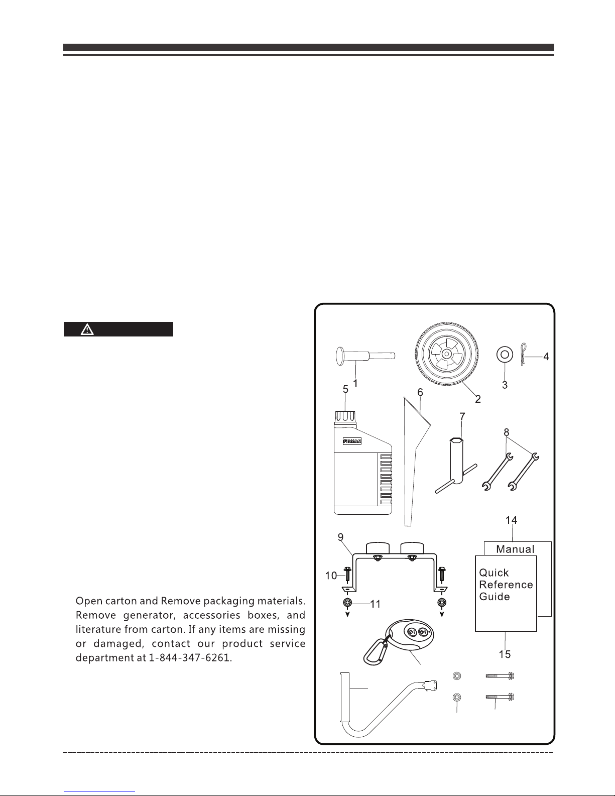
UNPACKING THE GENERATOR
•
•
Parts Included
Your gasoline powered generator ships with
the following parts:
1. Axle pin . . .. . . . . . . . . . . . . . . . . . . . . . . . . . . . . .2
2. 10.0" in. Wheel . . . . . . . . . . . . . . . . . . . . . . . . . 2
3. Flat Washer. . . . . . . . . . . . . . . .. . . . . . . . . . . . . .2
4. Cotter pin. . . . . . . . . . . . . . . . . .. . . . . . . . . . . . . .2
5. Engine Oil(Bottle) . . . .. . . . . . . . . . . . . . . . . . . .1
6. Oil Funnel . . . . .. . . . . . . . . . . . . . . . . . . . . . . . . . 1
7. Wrench for Spark plug . . . . . . . . . . . . . . . . . . . . 1
8. Double Open wrench (10mm & 12mm). . . . 2
9. Support Leg with Vibration Mounts . . . . . . 1
10. Flange Bolt (M8x16 for Support Leg) . . . . . 2
11. Flange Lock Nut (M8) . . . . . . . . . . . . . . . . . . . 4
12. Handle . . . . . . . . . . . . . . . . . . . . . . . . . . . . .. . . . 1
13. Flange Bolt (M8x50 for Handle) . . . . . . . . . 2
14. Manual. . . . . . . . . . . . . . . . . . . . . . . . . . . . . . 1
15. Quick Reference Guide . . . . . . . . . . . . . . . . . 1
16. Remote . . . . . . . . . . . . . . . . . . . . . . . . . . . . . . 1
16
English Customer Service: 1-844-FIRMAN1
12
11
13
Page 07
English Customer Service: 1-844-FIRMAN1
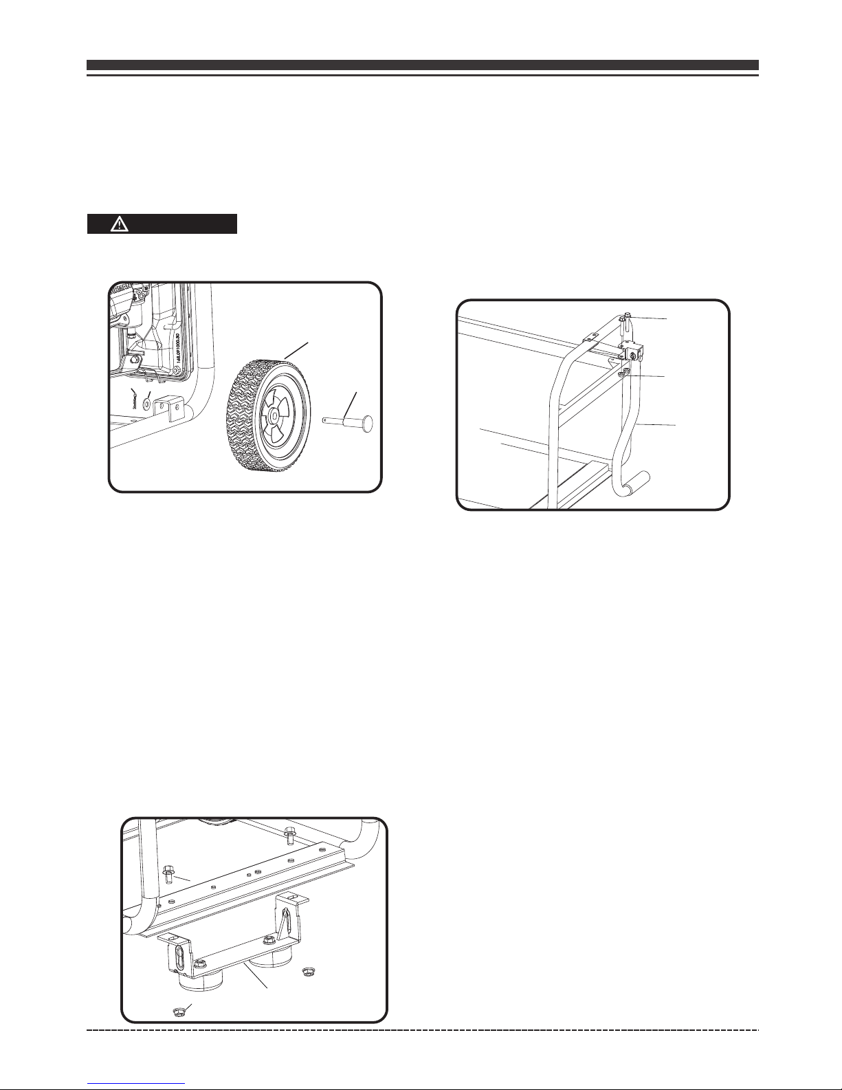
Install the Wheel Kit
The wheel kit is not intended for over-the-road
use.
Install the Support Leg
ASSEMBLY
Install the Handle
1. Place the handle K over the mounting channel
on the frame.
2. Secure the handle to the frame using the two
handle flange bolts H(M8x50).
3. Place a flange nut F (M8) on the end of each
bolt and fasten securely with provided
wrenches.
DO NOT over tighten the flange nuts.
A
B
C
F
The generator requires some assembly prior to
usage. If problems arise when assembling the
generator, call 1-844-347-6261.
F
E
G
H
K
1. Before adding wheels, tip the generator on
its side.
2. Slide the axle pin A through the wheel B.
3. Slide the axle pin A through the mount point
on the frame and flat washer D.
4. Secure the wheel and axle pin with the cotter
pin C.
5. Repeat steps 2-4 to attach another wheel.
1. Attach the support leg G to the generator
frame with flange bolts E (M8x16) and flange
lock nuts F(M8).
2. Tip the generator slowly so that it rests
on the wheels and support leg.
3.Tighten bolt E and nut F with provide
wrenches.
CAUTION
D
Page 08
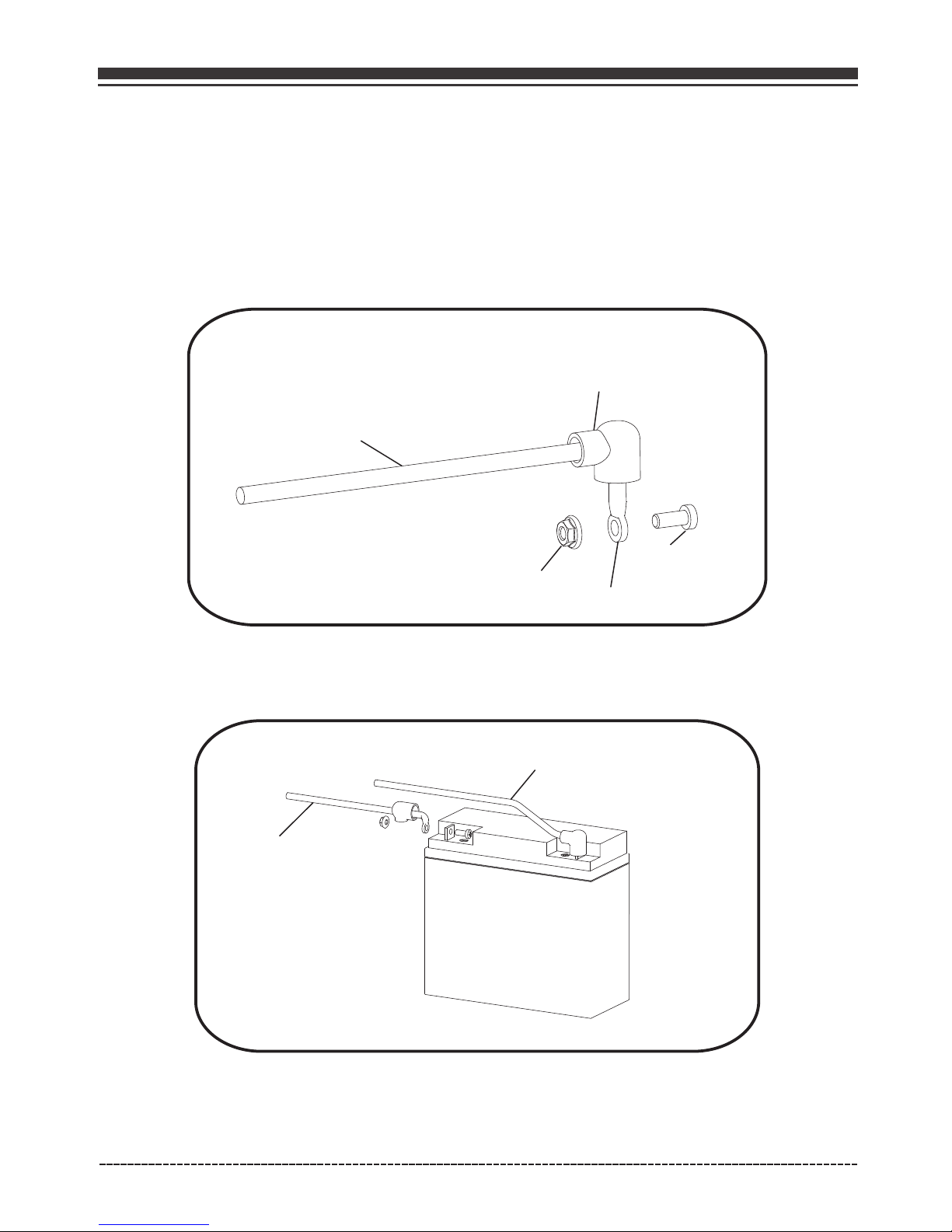
Battery Cable Connection
You will need to use 8mm box wrenches to connect the battery cables to battery.
NOTE:
The generator comes equiped with the positive red cable(red cable) already attached.
1. Verify the positive (+) battery cable (red boot) is securely tightened to the positive (+) battery
post. Make sure boot is over battery post.
2. Remove bolt M5X12 and M5 nut from black cable ring.
English Customer Service: 1-844-FIRMAN1
3. Remove vinyl cap from the negative(-) battery post. Locate negative (-) black cable and route
to the negative(-) battery post. Tight the cable with bolt M5X12 and M5 nut. Cover the post with
black boot.
M5X12
M5
Black Cable
Ring
Black Boot
Red Cable(+)
Black Cable(-)
-
+
Page 09
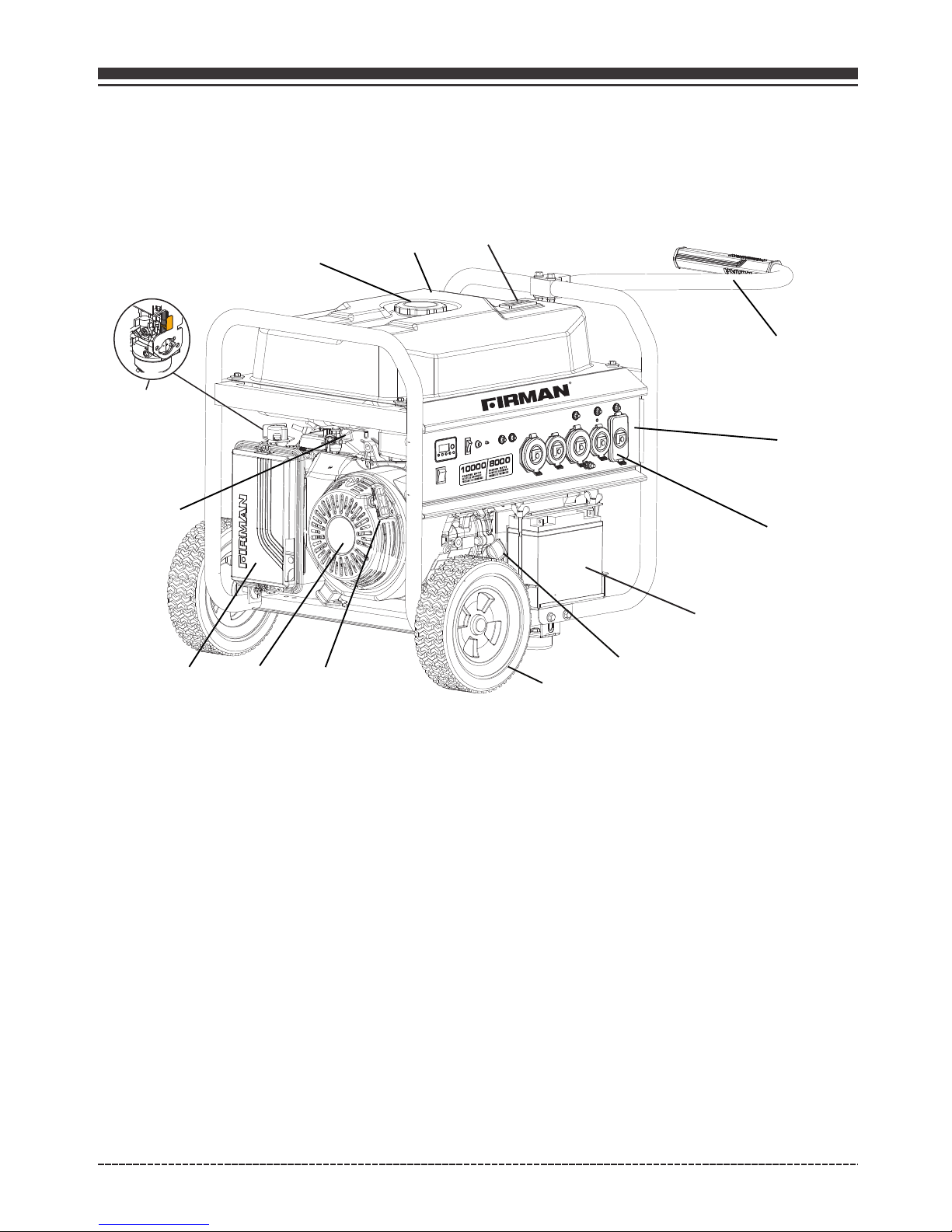
CONTROLS AND FEATURES
Generator
1- Fuel Gauge
2- 8.0 Gallon Capacity Fuel Tank
3- Fuel Cap
4- Choke Lever
5- Fuel Valve
6- Air Filter
7- 439cc FIRMAN OHV Engine
8- Recoil Starter
(behind air filter box)
9- 10.0" Flat Free Wheel
10- Oil Filler Cap
11- Outlet Cover
12- Control Panel
13- Handle
14- Battery
English Customer Service: 1-844-FIRMAN1
*We are always working to improve our products. Therefore, the enclosed product may differ
slightly from the image on this page.
1
①
②
③
④
⑤
⑥
⑦
⑧
⑨
⑩
⑪
⑫
⑬
⑭
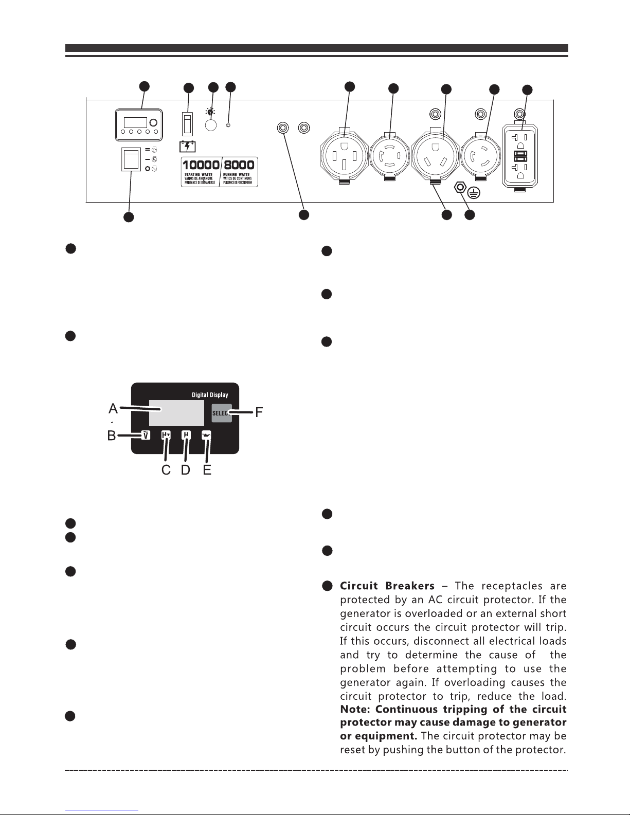
1
2
4-1 Data-Minder(Multi-Meter) – Push the
SELECT button to show the Voltage, Hertz and
running hours. If the low oil indicator is lit,
check the oil level.
3
4
5
8
Ground Terminal – Consult an electrician
for local grounding regulations.
Battery Switch – Power the electric starter.
10
11
Outlet Cover - Protect the receptacles from
dust and debris.
12
13
Page 10
NOTE:
Total power drawn from all receptacles must not exceed the name plate rating.
Engine Start Switch – Used to start engine
from the starter motor(Electric start model
only). To start engine, press and hold the
switch in the “START”(ll) position, the
engine will crank and attempt to start. When
the engine starts, release the switch to the
“RUN”(l) position.
Control Panel
A - Digital display
B - AC voltage indicator
C - Frequency indicator
D - Hour indicator
E - Low oil indicator
F - Select button
English Customer Service: 1-844-FIRMAN1
2
3
4
5
9
10
11
1
6
120V, 30A RV (NEMA TT-30R) -
120/240V, 50A – (NEMA 14-50R)
Ground Fault Circuit Interrupter conforms to UL 943,
and NEC requirements. This device protects
you against hazardous electrical shock that may be
caused if your body becomes a path through which
electricity travels to reach ground. This could happen
when you touch an appliance or cord that is “ live “
through faulty mechanism, damp or worn insulation, etc.
120V, 20A Duplex GFCI (Ground Fault
Circuit Interrupter) – (NEMA 5-20R)
Maximum 30 Amp current may be drawn from this 120
Volt receptacle.
This receptacle is rated so that a total of 20 amps
may be drawn regardless of whether both halves or
just one receptacle is used.
6
7
8
1213
120V, 30A Twist-Lock (NEMA L5-30R) -
9
Remote Start Program Button - Use this
button along with the remote control to program
the generator to be started remotely. Your remote
control is already programmed in factory for your
convenience. You might need programming when
using new remote control.
Supplies electrical power for the operation of
120/240 Volt AC, 50Amp, single phase. Maximum
full load current may be drawn from this receptacle.
If other receptacles are used at the same time, total
power used must be kept within nameplate.
7
120/240V, 30A Twist-Lock – (NEMA L14-30R)
Maximum 30 Amp current maybe drawn from this
120/240 Volt receptacle.
Remote Start Indicator Light - The light
will light or flash depending on the status of
the remote start system.
Maximum 30 Amp current may be drawn from this 120
Volt receptacle.
Page 11
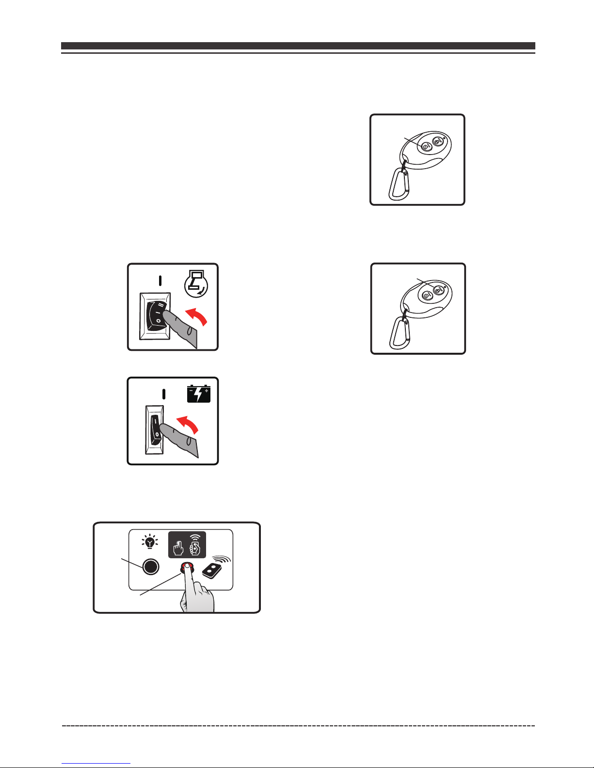
Remote Start
This generator is equipped with a wireless remote
start system for starting and stopping.
The Remote Start functions are enabled when:
1.The Engine Switch is in the “RUN”(l) position, AND
2.The Battery Switch is in the “ON”(l) position.
The Remote Start functions are disabled if either
of the above conditions is not met.
Remote Control Power Consumption
While the Engine Switch is in the “RUN”(l)
position and Battery Switch is in the “ON”(l)
position, the remote module is active and
waiting for a remote signal. This function
requires electrical current from the battery.
If the Battery Switch is left in the “ON”(l)
position for extended periods the battery can
be completely drained.
THE BATTERY SWITCH ALWAYS SHOULD BE IN
"OFF"(O) POSITION AT THE END OF USE TO
PREVENT BATTERY DRAIN.
NOTE:
English Customer Service: 1-844-FIRMAN1
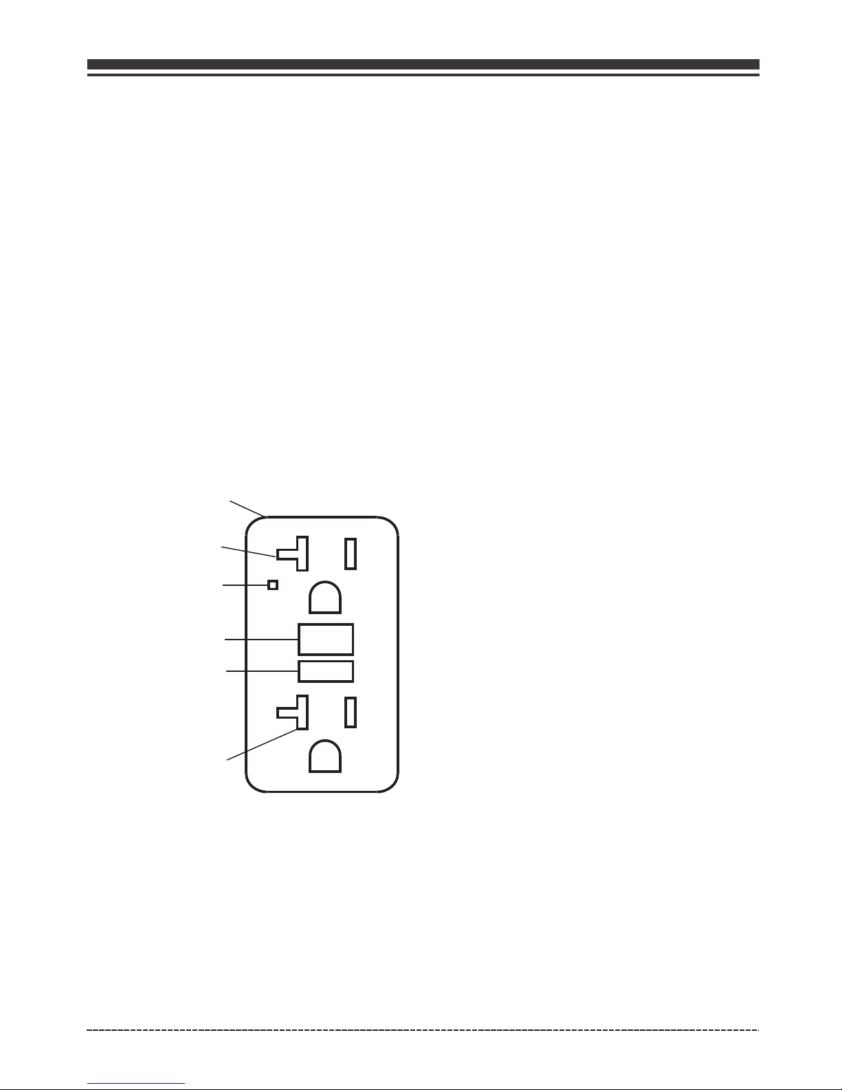
120VAC, 20AMP GFCI RECEPTACLE
This unit is equipped with a ground fault circuit
interrupter (GFCI). This device meets applicable
federal, state and local codes .
A GFCI receptacle does NOT protect against
circuit overloads, short circuits, or shocks. For
example, electric shock can still occur if a person
touches charged electrical wires while standing
on a non-conducting surface, such as a wood floor.
Definition: Instead of following its normal safe
path, electricity passes through a persons body
to reach the ground. For example, a defective
appliance can cause a ground fault.
A GFCI receptacle is different from conventional
receptacles. In the event of a ground fault, a GFCI
will trip and quickly stop the flow of electricity to
prevent serious injury.
1. Plug a test lamp into the receptacle.
2. Start the generator, the test lamp should be on.
3. Press the “Test” button located on the front
of the receptacle to trip the device.
4. This should stop the flow of electricity making
the lamp shut off. The GFCI’s indicator light comes
off.
RESET
TEST
TEST MONTHLY
FOLLOW DIRECTIONS
RESET BUTTON
Receptacle
Outlet
LED Indicator Light
TEST BUTTON
Outlet
5. To restore the flow of electricity, press the
“RESET” button on the front of the receptacle.
If the GFCI does not perform in this manner, do
not use the receptacle. Contact a local service
dealer or costumer service.
6. This outlet is protected against overload by
a 20A push-to-reset circuit breaker. Use the
outlet to power 120V AC, single-phase, 60 Hz,
electrical loads requiring up to a combined
2400 watts (2.4 kW) or 20 amps of current.
Testing the GFCI: Test the GFCI outlet every
month as follows:
SELF-TEST OPERATION
A Self-Test GFCI receptacle has all the features
of a conventional GFCI receptacle. In addition,
this receptacle tests itself periodically to confirm
the GFCI electronics are functional. The Indicator
Light will be solid green when the GFCI is powered
from Line side and working correctly.
Self-Test Indications: If the Indicator Light is solid
orange or flashing red a problem may exist.
Press the TEST button to trip the GFCI. If unable to
Reset, replace the GFCI.
Page 12
Remote Control Programming
1. Flip the engine switch to the "RUN"(l) position.
2. Flip the battery switch to the "ON"(l) position.
3. Push and hold the program button on the
control panel for approximately 3 seconds. The
remote start indicator light will light.
4. Push and release the ''STOP'' button on the
remote control. The indicator light will flash
once to erase the remote program.
STOP
5. Push and release the ''START'' button. The
indicator light will flash once to program the
remote.
START
6. Push and hold the program button approximately
3 seconds until the indicator light turn off. The
generator is now programmed to start remotely.
NOTE:
YOUR REMOTE CONTROL IS ALREADY PROGRAMMED IN
FACTORY FOR YOUR CONVENIENCE. AND IT IS READY TO
START THE GENERATOR.
English Customer Service: 1-844-FIRMAN1
Before the generator can be started , an initial
start-up procedure must be performed so the
generator and the remote control recognize
each other.
If the remote control is replaced then you will
need to go through following procedure with
new remote control.
Indicator
Light
Program Button
Page 13
SPECIFICATIONS
AN IMPORTANT MESSAGE ABOUT TEMPERATURE:
When operated above 77°F(25°C) there may be a decrease in power.
Maximum wattage and current are subject to and limited by such factors as fuel BTU content
ambient temperature, altitude, engine condition and etc. Maximum power decreases about
3.5% for each 1,000 feet above sea level; and will also decrease about 1% for each 10°F(-12.2°C)
above 60°F(16°C) ambient temperature.
•
•
English Customer Service: 1-844-FIRMAN1
Model
Rated AC Voltage
Phase
Power Factor
Voltage Regulator
Alternator Type
Running Watts
Starting Watts
Engine
Engine Type
Displacement
Low Oil Shutdown
Ignition System
Starting System
Fuel
Capacity Fuel Tank
Lubricating Oil Capacity
Carburetor Type
Air Cleaner
P.T.O. Shaft Rotation
120/240V
P08003
8000
AVR
Single
1
Single Cylinder, 4-Stroke OHV Air Cooled
439cc
Breakless Ignition Type, Flywheel Magneto
Unleaded Automotive Gasoline
8.0 Gallon
37.2 oz(1.1L)
Counter Clockwise (Facing P.T.O.)
Float
Brushed
Polyurethane Type
Yes
10000
FIRMAN
Rated Fequency
60Hz
Oil Type
See “Add Engine Oil” Section
Spark Plug
TORCH F6RTC/NGK BPR6ES/CHAMPION RN9YC
Recoil/Electric Start/Remote Start
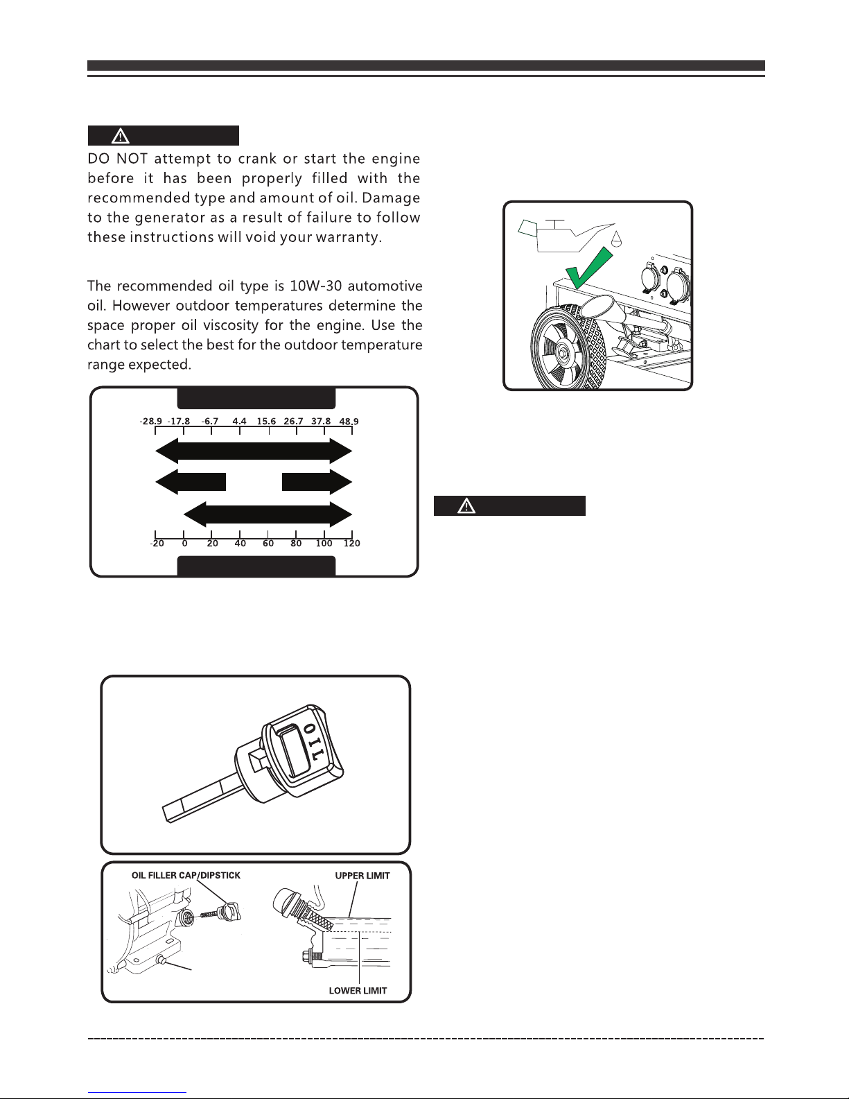
ADD ENGINE OIL
Page 14
1.Place generator on a flat, level surface.
2.Clean area around oil fill and remove yellow
oil fill cap/dipstick.
3.Wipe dipstick clean.
NOTE:
The engine is equipped with a low oil shut-off and
will stop when the oil level in the crankcase falls
below the threshold level.
NOTE:
We consider the first 5 hours of run time to be
the break-in period for the unit. During the break
in period stay at or below 50% of the running
watt rating and vary the load occasionally to allow
stator windings to heat and cool. Adjusting the
load will also cause engine speed to vary and help
seat piston rings.
CAUTION
The unit is equipped with a low oil shutdown.If
the oil level becomes lower than required,the
sensor will activate a warning device or stop the
engine.
If generator shuts off and the oil level is within
specifications, check to see if generator is sitting
at an angle that forces oil to shift. Place on an
even surface to correct this. If engine fails to
start, the oil level may not be sufficient to
deactivate low oil level switch. Make sure the
sump is completely full of oil.
(H)
DRA IN PLUG
(L)
5.Replace oil fill cap/dipstick and fully tighten.
6.Oil level should be checked prior to each use
or at least every 8 hours of operation. Keep oil
level maintained.
4.Using oil funnel, slowly pour contents of
provided oil bottle into oil fill opening to the
"H" mark on dipstick. Be careful do not
overfill. Overfilling with oil could cause the
engine to not start or hard starting.
Low Oil Shutdown
Degrees Celsiusº(Outside)
Full Synthetic 5W-30
Degrees Fahrenheitº(Outside)
5W-30 10W-40
10W-30
CAUTION
H
L
English Customer Service: 1-844-FIRMAN1
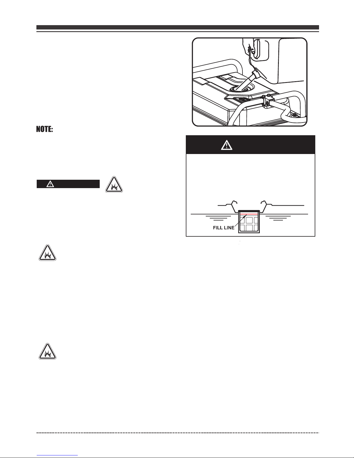
ADD FUEL
Page 15
Fuel must meet these requirements:
•
Clean, fresh, unleaded gasoline.
Use regular UNLEADED gasoline with the
generator engine with a minimum 87 octane
/ 87 AKI (91 RON).
For high altitude use, see "Operation at High
Altitude".
Do not use gasoline with more than 10%
alcohol such as E85 or ethanol.
•
•
Failure to follow Operator's Manual for fuel
recommendations voids warranty.
Avoid generator damage.
DO NOT use unapproved gasoline such as E85.
DO NOT mix oil in gasoline.
DO NOT modify engine to run on alternate fuels.
•
•
•
WARNING
Fuel and its vapors are extremely flammable
and explosive which could cause burns, fire or
explosion resulting in death, serious injury
and/or property damage.
WHEN ADDING FUEL
Fill fuel tank outdoors.
DO NOT overfill tank. Allow space for fuel
expansion. If the tank is overfilled, fuel
can overflow onto a hot engine and cause fire
or explosion. Wipe up any spilled fuel
immediately.
If fuel spills, wait until it evaporates before
starting engine.
Keep fuel away from sparks, open flames,
pilot lights, heat, and other ignition sources.
Check fuel lines, tank, cap and fittings
frequently for cracks or leaks. Replace if
necessary.
DO NOT light a cigarette or smoke when
filling the fuel tank.
•
•
•
•
1.Clean area around fuel fill cap, remove cap.
2.Slowly add unleaded fuel to fuel tank. Be
careful not to fill above the red fuel level
indicator . This allows adequate space for
fuel expansion.
3.Install fuel cap and let any spilled fuel
evaporate before starting engine or wipe up
any spilled gasoline.
CAUTION
Slowly add unleaded gasoline to fuel tank.
Do not overfill tank.
Do not fill above top of fuel screen. This
will all expansion in hot weather and
prevent overflow.
•
•
•
Operation at High Altitude
At altitudes over 5,000 feet(1524 meters), a
minimum 85 octane / 85 AKI (89 RON) gasoline
is acceptable.
The density of air at high altitude is lower
than at sea level. Engine power is reduced
as the air mass and air-fuel ratio decrease.
Engine power and generator output will be
reduced approximately 3.5% for every 1000 feet
of elevation above sea level. This is a
natural trend and cannot be changed by
adjusting the engine. At high altitudes
increased exhaust emissions can also result
due to the increased enrichment of the air
fuel ratio.
Other high altitude issues can include hard
starting, increased fuel consumption and
spark plug fouling. To alleviate high
altitude issues other than the natural
power loss, FIRMAN can provide a high
altitude carburetor main jet. The alternative
English Customer Service: 1-844-FIRMAN1
Page 16
Altitude main jet 1
Altitude main jet 2
439cc
380717002
380717003
Altitude
3000-6000Feet
6000-8000Feet
OPEN
WARNING
Grounding
The National Electric Code requires your generator
must be properly connected to an appropriate
ground to help prevent electric shock.
Failure to properly ground the
generator can result in electric
shock.
WARNING
THERE IS A PERMANENT CONDUCTOR BETWEEN
THE GENERATOR (STATOR WINDING) AND THE
FRAME.
Use approved transfer equipment to prevent
backfeed by isolating generator from electric
utility workers.
When using generator for backup power, notify
utility company.
Use a ground fault circuit interrupter (GFCI) in
any damp or highly conductive area, such as
metal decking or steel work.
DO NOT touch bare wires or receptacles.
DO NOT use generator with electrical cords
which are worn,frayed, bare or otherwise
damaged.
DO NOT operate generator in the rain or wet
weather.
DO NOT handle generator or electrical cords
while standing in water, while barefoot, or
while hands or feet are wet.
DO NOT allow unqualified persons or children
to operate or service generator.
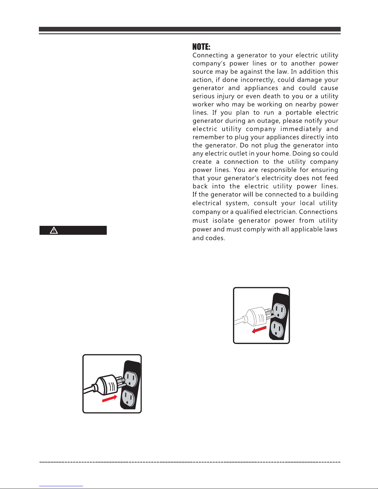
Connecting to a Building's Electrical System
WARNING
Generator voltage could cause
electrical shock or burn resulting
in death or serious injury.
•
•
•
•
•
•
•
•
The part number and recommended minimum
altitude for the application of the high
altitude carburetor main jet is listed in the
table below.
main jet and installation instructions can be
obtained by contacting Customer Support.
Installation instructions are also available in the
Technical Bulletin area of the FIRMAN internet site.
English Customer Service: 1-844-FIRMAN1
5. OPERATION
Page 17
Generator Location
Make sure you review each warning in order to
prevent fire hazard.
Keep area clear of inflammables or other
hazardous materials.
Select a site that is dry, well ventilated and
protected from the weather.
Keep exhaust pipe clear of foreign objects.
Keep generator away from open flame.
Keep generator on a stable and level surface.
WARNING
Surge Protection
Voltage fluctuation may impair the proper
functioning of sensitive electronic equipment.
WARNING
POISONOUS GAS HAZARD.
•
•
•
•
Do not block generator air vents with paper or
other material.
CAUTION
Tilting can cause fuel spillage.
CAUTION
English Customer Service: 1-844-FIRMAN1
Page 18
Starting the Generator (Recoil Start)
1. Before starting the generator, check for loose
or missing parts and for any damage which
may have occurred during shipment.
2. Check oil level and fuel.
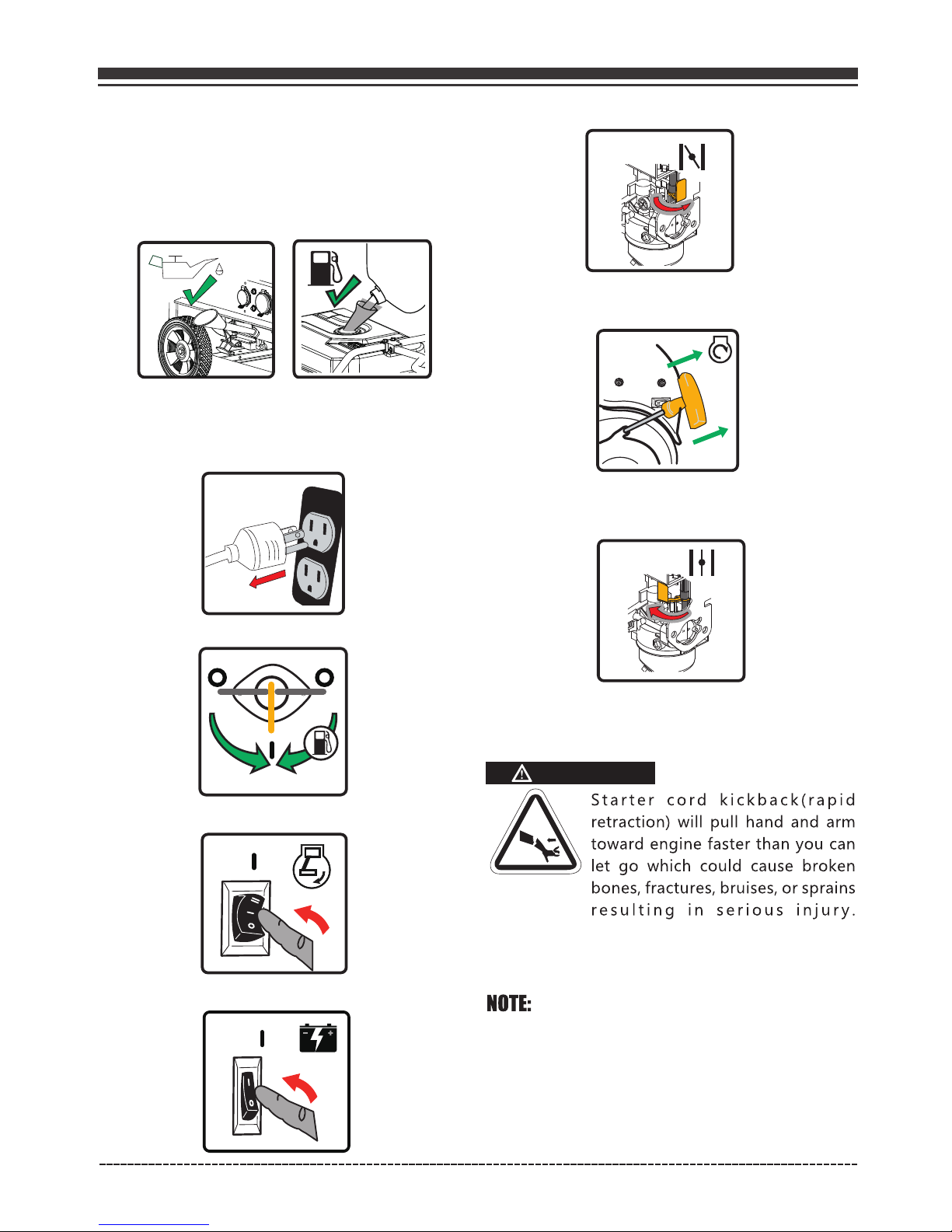
7. Move the choke lever to the “START” position.
5. Flip the engine switch to the “RUN(l)” position.
9. Do not over-choke. As soon as engine starts
and warms up, move the choke lever to the
“RUN” position.
10. Allow generator to run at no load for few
minutes upon each initial start-up to permit
engine and generator to stablize.
WARNING
When starting engine, pull cord slowly until
resistance is felt and then pull rapidly to avoid
kickback.
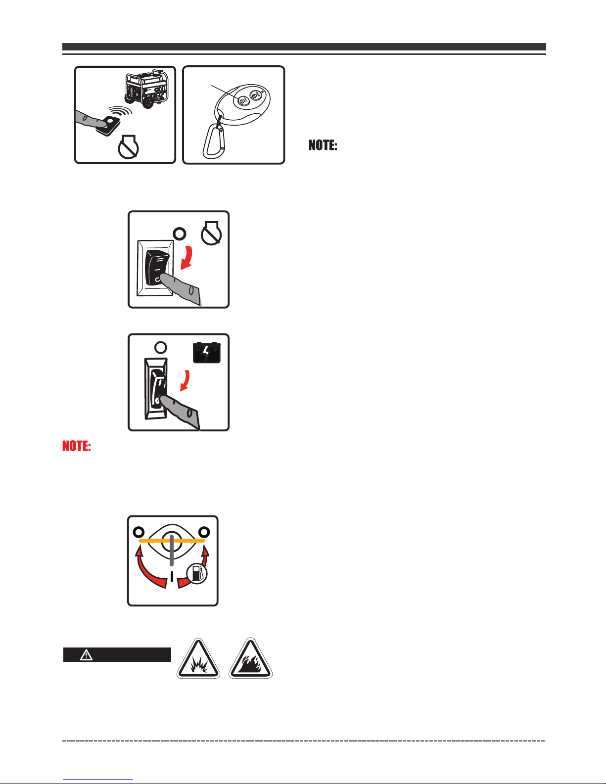
4. Turn the fuel valve to the “ON” (l)position.
8. Pull the starter cord slowly until resistance is
felt and then pull rapidly.
3. Disconnect all electrical loads from the
generator. Never start or stop the generator
with electrical devices plugged in or turned
on.
English Customer Service: 1-844-FIRMAN1
Keep choke lever in “START” position for only 1
pull of the recoil starter. After first pull, move
choke lever to the “RUN” position for up to the
next 3 pulls of the recoil starter. Too much
cho ke leads to sparkplug fou ling/engine
flooding due to the lack of incoming air. This
will cause the engine not to start.
6. Flip the battery switch to the "ON"(l) position.
Page 19
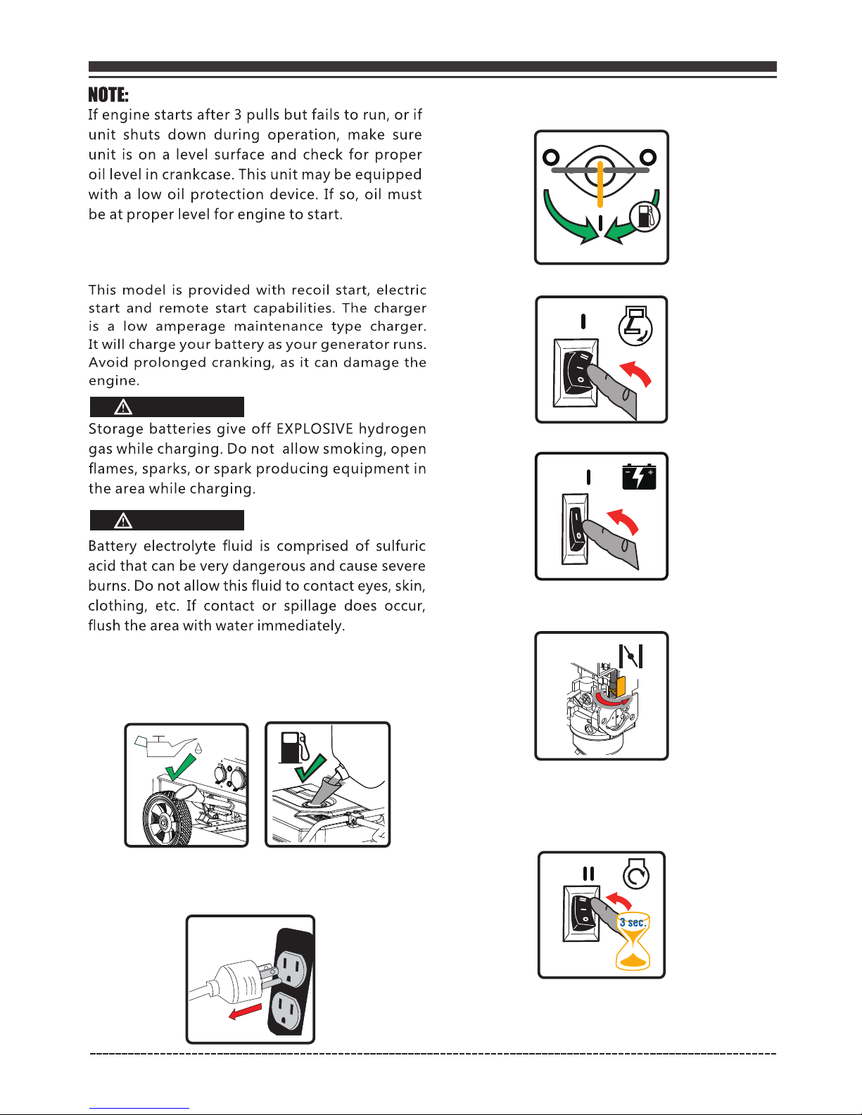
Starting the Generator (Electric Start)
Electric Start and Remote Start Operations
WARNING
WARNING
1. Before starting the generator, check for loose
or missing parts and for any damage which
may have occurred during shipment.
2. Check oil level and fuel.
3. Disconnect all electrical loads from the
generator. Never start or stop the generator
with electrical devices plugged in or turned on.
4. Turn the fuel valve to the “ON” (l)position.
5. Flip the engine switch to the "RUN"(l) position.
6. Flip the battery switch to the "ON"(l) position.
7. Move the choke lever to the “START” position.
8. Press and hold the engine switch in the "START"(ll)
position for few seconds and release the switch to the
"RUN"(l) position.
English Customer Service: 1-844-FIRMAN1

Page 20
9. Do not over-choke. As soon as engine starts
and warms up, move the choke lever to the
“RUN” position.
10. Allow generator to run at no load for few
minutes upon each initial start-up to permit
engine and generator to stablize.
1. Before starting the generator, check for loose
or missing parts and for any damage which
may have occurred during shipment.
2. Check oil level and fuel.
English Customer Service: 1-844-FIRMAN1
Starting the Generator (Remote Start)
NOTE:
YOUR REMOTE CONTROL IS ALREADY PROGRAMMED IN
FACTORY FOR YOUR CONVENIENCE. AND IT IS READY TO
START THE GENERATOR.
If the remote control is replaced, then you will
need to go through programming procedure in
"Remote Control Programming" section.
3. Disconnect all electrical loads from the
generator. Never start or stop the generator
with electrical devices plugged in or turned
on.
5. Flip the engine switch to the “RUN”(l) position.
4. Turn the fuel valve to the “ON” (l)position.
6. Flip the battery switch to the "ON"(l) position.
7. Push and release the ''START'' button on the
remote control.
The generator will turn over for 3 to 5 seconds
and start.
.
START
An engine warmup delay is programmed into
the remote start cycle. After the generator is
running, there will be a delay of electrical
output for 15 seconds.
Page 21
If the generator fails to start after a total of six
attempts, the start button on the remote control
must be pushed again to begin another cycle of
six start attempts.
8. Allow generator to run at no load for few
minutes upon each initial start-up to permit
engine and generator to stablize.
Connecting Electrical Loads
1.Let engine stabilize and warm up for a few
minutes after starting.
2.Ensure circuit breaker on control panel is in
on position.
3.Plug in and turn on the desired 120 or 240 Volt
AC, single phase, 60Hz electrical loads. It is
better to attach the item with largest load first.
This unit has been pretested and adjusted to
handle its full capacity. Before starting the
generator, disconnect all load. Apply load only
after generator is running. Voltage is regulated
via the engine speed adjusted at the factory for
correct output. Readjusting will void warranty.
CAUTION
When applying a load, do not exceed the maximum
wattage rating of the generator when using one or
more receptacles. Also, do not exceed the amperage
rating of any one receptacle.
Do not apply heavy electrical load during break-in
period (the first five hours of operations).
If the engine fails to start within 3 to 5 seconds,
the engine will attempt to start five additional
times. If the generator failed to start, the remote
start indicator light will flash.
English Customer Service: 1-844-FIRMAN1
Stopping the Engine
1. Turn off and remove entire electrical loads.
Never start or stop the generator with
electrical devices plugged in or turned on.
Let the generator run at no-load for two
minutes to stabilize internal temperatures
of the engine and generator.
2. Remote Start Operation
Push and release the "STOP" button on the
remote control. The generator will run for an
additional 15 seconds as it goes through a
cool down cycle before shutting off.
Note: Skip this step and go to step 3, if you are
not using Remote Start to shutdown the engine.
Page 22
WARNING
If a cover is used, do not install until unit has cooled.
Fuel and its vapors are extremely flammable and
explosive which could cause burns, fire or
explosion resulting in death, serious injury
and/or property damage.
Flip the engine switch to“OFF”(O) position.
5. Turn the fuel valve to the “OFF”(O) position.
STOP
3. Electric Start and Recoil Start Operations
4. Flip the battery switch on "OFF"(O) position.
STOP
THE BATTERY SWITCH ALWAYS SHOULD BE IN
"OFF"(O) POSITION AT THE END OF USE TO
PREVENT BATTERY DRAIN.
English Customer Service: 1-844-FIRMAN1
DO NOT stop engine by moving choke control
to “START” position.
Important: Always ensure that the Fuel Valve
and the Engine Switch are in the “OFF” position
when the engine is not in use.
If the engine will not be used for a period of two
weeks or longer, please see the Storage section
for proper engine and fuel storage.
Low Oil Shutdown
If the engine oil drops below a preset level, an
oil switch will stop the engine. Check oil level
with dipstick.
If oil level is between LOW and HIGH mark on
dipstick:
1.DO NOT try to restart the engine.
2.Contact an Authorized FIRMAN Service Dealer.
3.DO NOT operate engine until oil level is
corrected.
If oil level is below LOW mark on dipstick:
1.Add oil to bring level to HIGH mark.
2.Restart engine and if the engine stops again
a low oil condition may still exist. DO NOT try
to restart the engine.
3.Contact an Authorized FIRMAN Service Dealer.
4.DO NOT operate engine until oil level is
corrected.
Do Not Overload Generator
Overloading a generator in excess of its rated
wattage capacity can result in damage to the
generator and to connected electrical devices.
To prolong the life of your generator and
attached devices, follow these steps to add
electrical load:
1. Start the generator with no electrical load
attached.
2. Allow the engine to run for several minutes
to stabilize.
3. Plug in and turn on the first item. It is best to
attach the item with the largest load first.
4. Allow the engine to stabilize.
5. Plug in and turn on the next item.
6. Allow the engine to stabilize.
7. Repeat steps 5-6 for each additional item.
 Loading...