

Page 1
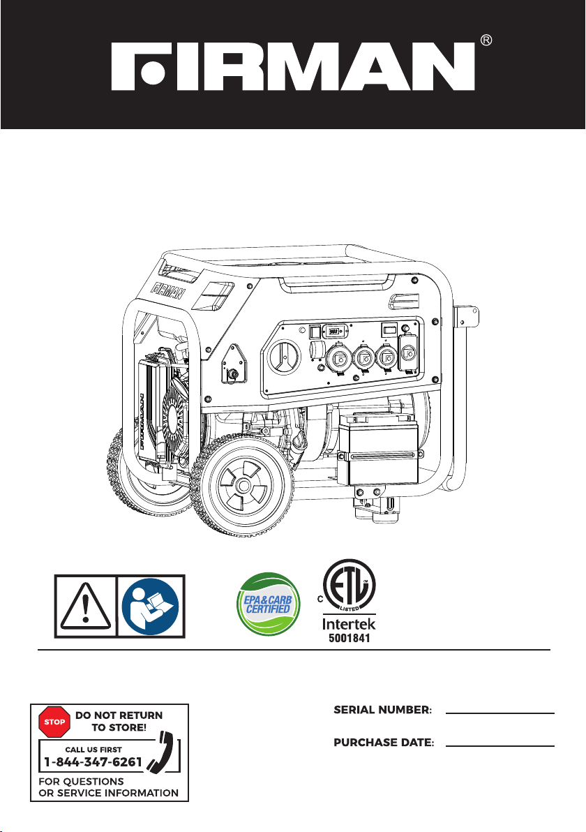
OPERATOR’S MANUAL
DUAL FUEL PORTABLE GENERATOR
MODEL NUMBER
H08052
Rev Level:00
Record product information to reference when ordering parts or
obtaining warranty coverage.
P/N:38074 7010 Re v:01
Page 2
INTRODUCTION
Table of Contents
Introduction . . . . . . . . . . . . . . . . . . . . . . . . . . . . . . . . . . . . . . . . . . . . . . . . . . . . . . . . . . . . . . . . .. . . . .1
Features and Controls . . . . . . . . . . . . . . . . . . . . . . . . . . . . . . . . . . . . . . . . . . . . . . . . . . . . . . . . . . . 5
Operation . . . . . . . . . . . . . . . . . . . . . . . . . . . . . . . . . . . . . . . . . . . . . . . . . . . . . . . . . . . . . . . . . . . . . . 10
Maintenance - Storage. . . . . . . . . . . . . . . . . . . . . . . . . . . . . . . . . . . . . . . . . . . . . . . . . . . . . . . . . . 25
Troubleshooting- Specifications . . . . . . . . . . . . . . . . . . . . . . . . . . . . . . . . . . . . . . . . . . . . . . . . 32
Parts Diagrams - Parts Lists - Wiring Diagram . . . . . . . . . . . . . . . . . . . . . . . . . . . . . . . . . . . . 34
Service - Warranty. . . . . . . . . . . . . . . . . . . . . . . . . . . . . . . . . . . . . . . . . . . . . . . . . . . . . . . . . . . . . .40
REGISTER YOUR PRODUCT
Register your product using the QR code provided or at
www.firmanpowerequipment.com .
INTRODUCTION
Thank you for purchasing a FIRMAN generator. You have selected a high-quality, precision engineered
generator set designed and tested to give you years of satisfactory service. This generator is Dual Fuel
and capable of running on gasoline and liquid petroleum gas (LPG). This generator is not intended to
be run unattended or to supply power to life safety support.
This man ual contains sa fety informa tion to make you aware of the h azards and risk s associated
with generator products and ho w to avoid the m. This generator is de signed an d inten ded only
for suppl ying electrical p ower for operatin g compatible el ec trical lighti ng, appliances, t ools and
motor loads, and is not intended for any other purpose. It is important that you read and
underst and these inst ructions thorou ghly before at tempting to st art or operate th is portable
generat or. Save these orig inal instructio ns for future ref er ence.
All information in this publication is based on the latest production information available at the
time of approval f or p ri nt in g. The manufacturer reserves the right to change, a lt er o r otherwise
improve the generator and this documentation at any time without prior notice.
01
Page 3
SIGNAL WORDS
INTRODUCTION
DANGER WARNING CAUTION
Indicat es a hazard
which, if n ot avoided,
will resu lt in death or
serious i njury.
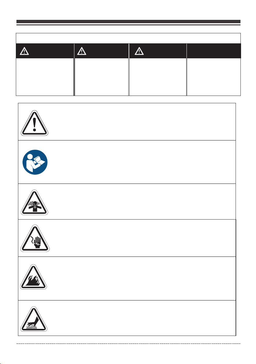
Safety Alert Symbol- Indicates a potential personal injury hazard.
Operator's Manual- Failure to follow warnings, instructions and
operator's manual could result in death or serious injury.
Toxic Fumes- Engine exhaust contains carbon monoxide, a
poisonous gas that will kill you in minutes. You cannot smell
it or see it.
Indicat es a hazard
which, if n ot avoided,
could res ult in death
or seriou s injury.
Indicat es a hazard
which, if n ot avoided,
could res ult in minor or
moderat e injury.
NOTI C E
Indicates information
considered Important,
but not hazard-related.
Generator could cause electrical shock resulting in death or serious
injury.
Fire- Fuel and its vapors are extremely flammable which could
cause burns or fire resulting in death or serious injury.Engine
exhaust could cause fire resulting in death or serious injury.
Hot Surface- Muffler could cause burns resulting in serious injury.
Engli sh Cu stome r Servi ce: 1-8 44-FI RMAN1
02
Page 4
INTRODUCTION
WARNING! This product can expose you to chemicals including gasoline engine
exhaust, which is known to the State of California to cause cancer, and carbon
monoxide, which is known to the State of California to cause birth defects or other
reproductive harm. For more information go to www.P65Warnings.ca.gov.
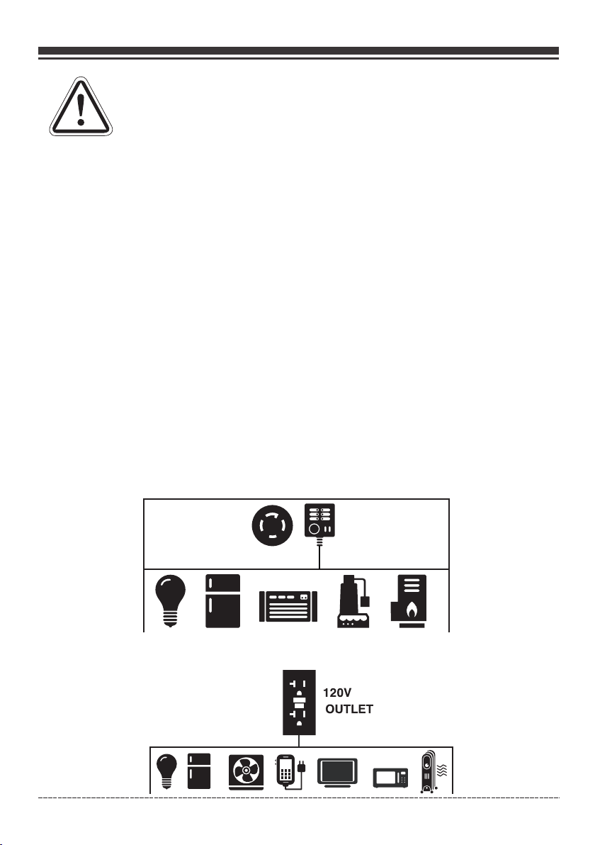
This outd oor generator can b e used to power outdo or items using ex tension cords or to r estore
home powe r using a transfer sw itch. A transfer sw itch is a separat e device installe d by a licensed
electri cian that allows th e portable genera tor to be cord conn ec ted, using eith er of the 120/240V
recepta cles, directly in to your home’s elec trical system . In stall a listed tr ansfer switch as so on as
possibl e if this generator w ill be used to restor e power to your hom e.
NO TI CE If y ou have questions a bout intended use , contact FIRMAN cu stomer service. T his portable
generat or is designed to be us ed only with FIRMAN a uthorized par ts.
System Ground
The generato r has a system ground that connect s the generator frame components to the ground
terminals on t he AC output recept acles. T he system ground is connect ed to the AC neutral wi re.
The neutral is bonded to the gen erator frame.
Compliance Requirements
There may b e Federal or State re gulations, loca l codes, or ordin ances that apply to t he intended
use of the ge nerator. Consul t a qualified elect rician, elect ri cal inspector , or the local agency
having ju risdiction. Thi s generator is not in tended to be used a t a construction si te or similar
activit y as defined by NFPA 70 -2020 (NEC) secti on 590.6.
ToRestoreHomePowerUsingaListedTransferSwitch
Connect ions to your home’s e lectrical syste m must use a listed * transfer switch i nstalled by a
license d electrician. Th e connection must i solate the gene ra tor power from th e utility power and
comply wi th all applicable l aws and electrica l codes.
Typical
120/240V
Transfer
Switch
Outlet
Typical I ndoor Items
To Restore Power Using Extension Cords
Engli sh Cu stome r Servi ce: 1-8 44-FI RMAN1
03
Page 5
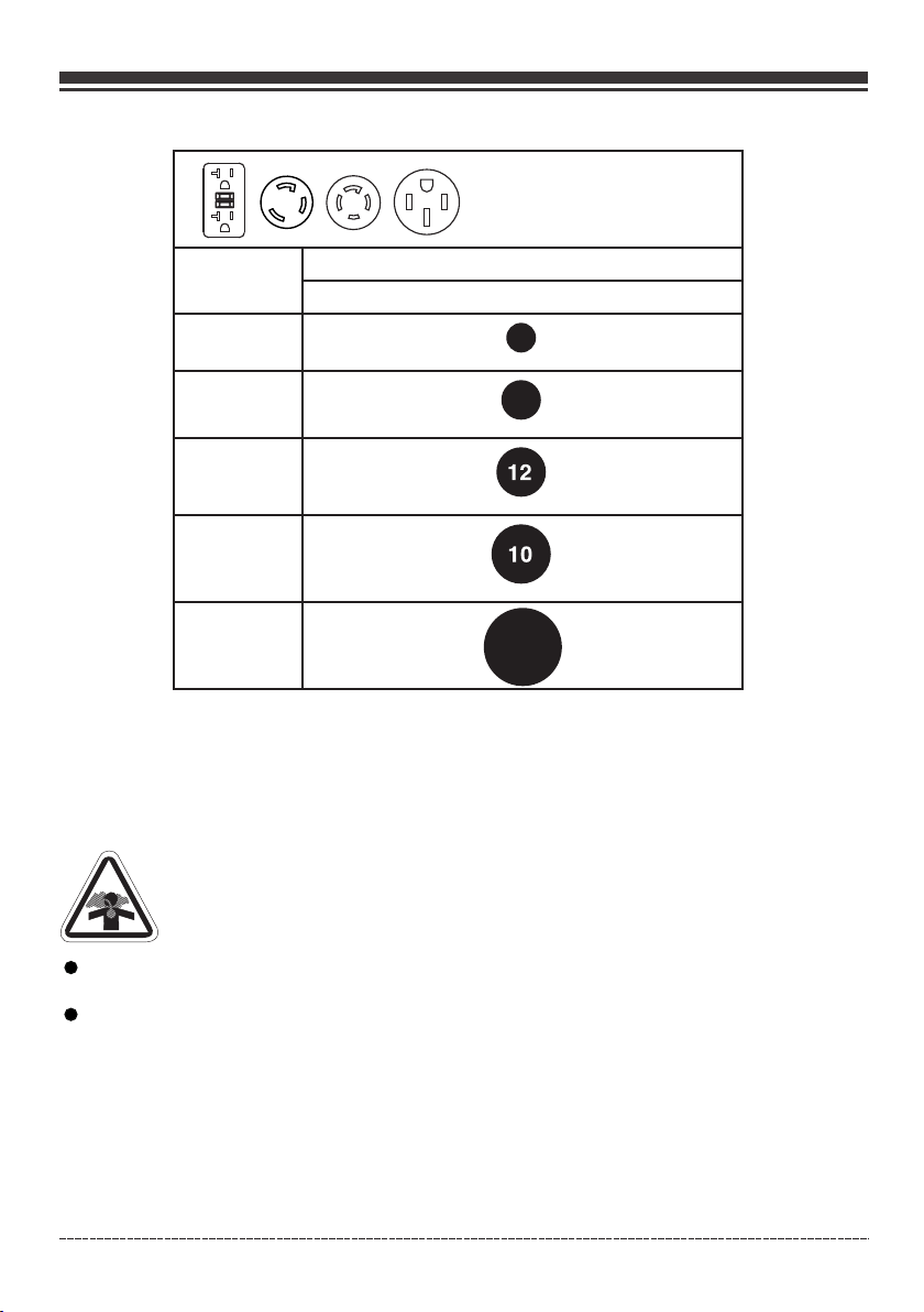
1. Only use g rounded cords mar ked for outdoor use r ated for your loa ds.
To provide power using
extension co rds
INTRODUCTION
Total
Amperage
Up to 13A
Up to 15A
Up to 20A
Up to 30A
Up to 50A
2. Follow cord safety instructions.
3. Install carbon monoxide alarm(s).
4. When operating portable generator with extension cords, make sure portable generator is located
downwind in an open, outdoor area, at least 20 ft. (6 m.) from occupied spaces with exhaust pointed
away.
5. Extension cords running directly into your home, powering indoor items IS NOT RECOMMENDED.
DANGER! Engine exhaust contains carbon monoxide, a poisonous gas that will kill
you in minutes. You cannot smell it, see it, or taste it. Even if you do not smell exhaust
fumes, you could still be exposed to carbon monoxide gas.
Minimum Gauge, Outdoor Rated
Up to 50 FT (15m)
16
14
6
Extensi on cords running di rectly into the hom e increase your r is k of carbon monox ide
poisoni ng through any open ings.
If an exten sion cord running d irectly into your h ome is used to powe r indoor items, the
operato r recognizes that t his increases the r isk of CO poisoni ng t o people inside t he home
and assum es that risk.
6. Install a listed *tr ansfer switch as soon as po ssible if this or any gener ator will be used to restor e
power to your home.
*Certified by a Nationally Recognized Testing Laboratory that the product complies to appropriate
product safety test standards.
Engli sh Cu stome r Servi ce: 1-8 44-FI RMAN1
04
Page 6
FEATURES AND CONTROLS
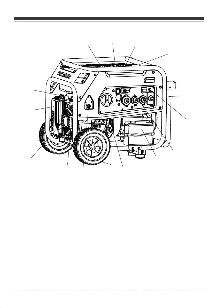
Generator
④
⑤
⑥
⑦
③
⑭
2
②
⑧
①
⑮
⑬
⑫
⑪
⑩
⑨
1- Fuel Gauge
2- 8.0 Gallon Capacity Fuel Tank
3- Fuel Cap
4- Choke Lever(behind air filter box)
5- Air Filter
6- 439cc FIRMAN OHV Engine
7- Recoil Starter
8- 10.0" Flat Free Wheel
9- Oil Filler Cap
*We are always working to improve our products. Therefore, the enclosed product may differ
slightly from the image on this page.
Engli sh Cu stome r Servi ce: 1-8 44-FI RMAN1
10- Battery
11- Outlet Cover
12- Control Panel
13- Handle
14- LPG Hose Connector(Inlet)
15. Data Decal / Serial Number
05
Page 7
FEATURES AND CONTROLS
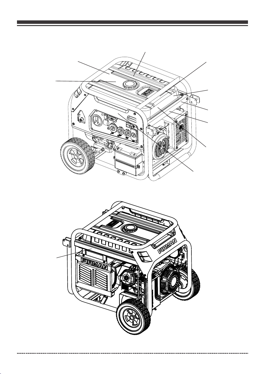
④
①
②
③
⑤
⑥
⑦
⑧
⑨
⑩
Engli sh Cu stome r Servi ce: 1-8 44-FI RMAN1
06
Page 8
FEATURES AND CONTROLS
Engli sh Cu stome r Servi ce: 1-8 44-FI RMAN1
07
Page 9
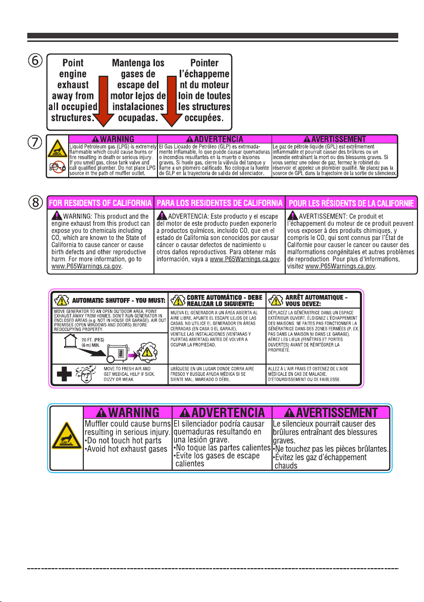
⑨
FEATURES AND CONTROLS
⑩
Engli sh Cu stome r Servi ce: 1-8 44-FI RMAN1
08
Page 10
FEATURES AND CONTROLS
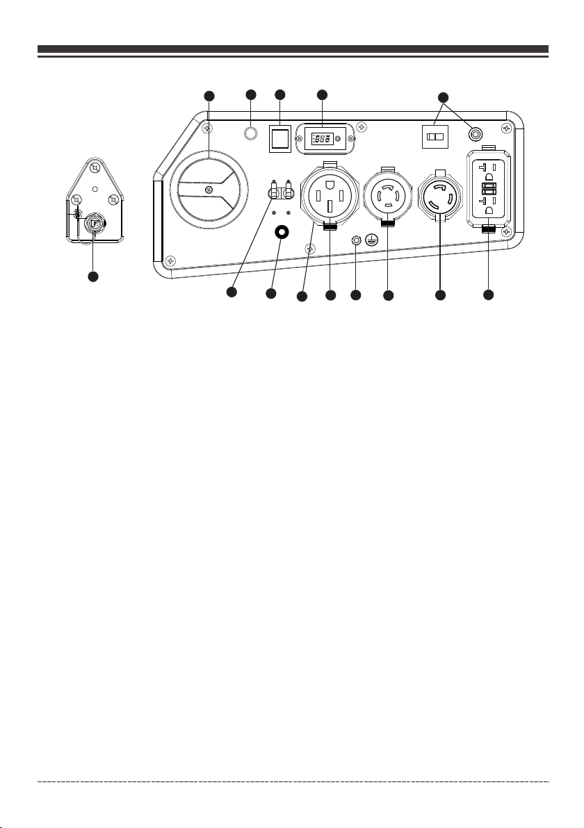
Control Panel
3
1
12
2
5
13
NO TI CETotal power drawn from all receptacles must not exceed the data decal rating.
1. Fuel Selector Switch – Use to select and turn on gasoline or LPG fuel source. Fuel (gasoline) valve is
closed when the switch is on “OFF” or “LPG” positions. Engine switch is on when the switch is on
“GAS” or “LPG” positions.
2. Indicator Light – Wh en the main fuel sele ctor switch is turn ed to the GAS or LPG posi tion,
the indic ator light will tur n RED for up to 4 minutes ( before going of f) . Starting the en gine
success fully anytime dur ing the 4 minutes wil l turn the indica to r light GREEN. Se e Indicator
light-B attery Power Savi ng Mode section for m ore informati on .
3. Engine Start Switch – To start engine, press and hold the switch in the START (ll) position, the
engine will crank and attempt to start. When the engine starts, release the switch to the RUN (l) position.
4. 3-1 Data-Minder (Multi-Meter) – Push the SELECT button to show the Voltage, Hertz and running hours.
5. Circuit B reakers – The r eceptacles are pr otected by AC circu it protectors. If t he generator is
overloa ded or an external sh ort circuit occur s, a circuit prot ec tor may trip. If tr ipping occurs,
disconn ect all electrica l loads and determi ne the cause befo re a ttempting to co ntinue using the
generat or. Reset any tripp ed circuit protec tors.
If multip le receptacles ar e used at the same time , the total curre nt m ust be kept with- in the
portabl e generator data decal rating.
6. 120V, 20A Duplex GFCI (Ground Fault C ircuit Interrup ter)- NEMA 5-20R
A maximum o f 20 Amps current may b e drawn from this dup lex receptacl e.
7. 120V, 30A Twist Lock – NE MA L5-30R(Not GFC I protected)
A maximum o f 30 Amps current may b e drawn from this rec eptacle.
8. 120/240 V, 30A Twist Lock – NEMA L14-30 R(Not GFCI protec ted)
A maximum of 30 Amps current for 240 Volts or two independent 120 Volt loads at 30 Amps current each.
9. Ground Terminal – Cons ult an electricia n or authority havi ng jurisdiction f or local ground ing
require ments.
10. 120/240V, 50A – (NEMA 14-50R) (Not GFCI protected)
A maximum of 33.33 Amps current for 240 Volts or two independent 120 Volt loads at 33.33 Amps current each.
11. Outlet Cover - Protects the r eceptacles fr om dust and debris.
12 . LPG Hose Connector (Inlet: 3/8" F lare Male) – Used to co nnect LPG hose to gen erator.
13. CO Alert™ Carbon Monoxide (CO) Shutdown Indicator Light — Indicates the engine shutdown due
to carbon monoxide accumulation around the generator or a CO Alert system fault occurred.
Engli sh Cu stome r Servi ce: 1-8 44-FI RMAN1
4
9
10
11
09
8
5
7
6
Page 11
OPERATION
1. Location
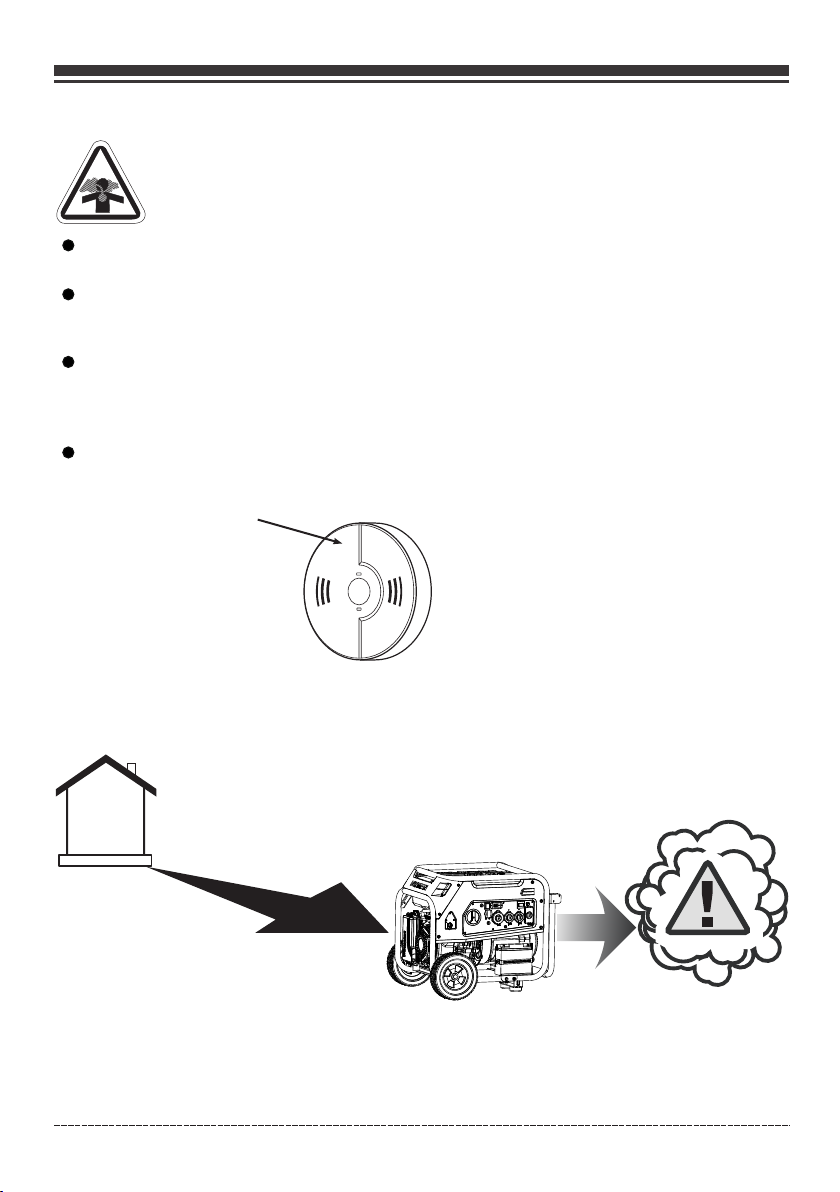
DANGER! Engine exhaust contains carbon monoxide, a poisonous gas that could kill
you in minutes. You CANNOT smell it, see it, or taste it. Even if you do not smell exhaust
fumes, you could still be exposed to carbon monoxide gas.
Operate p ortable generat or only outdoors an d downwind at lea st 2 0 ft.(6 m) from occ upied
spaces wi th exhaust pointe d away to reduce the ri sk of carbon mono xide accumulati ng.
Instal l battery- op er ated car bo n monoxide alarms o r plug-in c arbon mo no xide alarm s with
batter y back-up acc or ding to the m anufacturer 's i nstructions . Smoke alarm s cannot dete ct
carbon m onoxide gas .
Do not run this portable generator inside homes, garages, basements, crawlspaces, sheds, or
other partially-enclosed spaces even if using fans or opening doors and windows for ventilation.
Carbon monoxide can quickly build up in these spaces and can linger for hours, even after this
product has shut off.
If you start to feel sick, dizzy, weak or your home’s carbon monoxide alarm sounds, get to fresh air
right away. Call emergency services. You may have carbon monoxide poisoning.
Carbon M onoxide Alarm (s)
Install carbon monoxide alarms
in s ide yo u r h ome . Wi tho u t
work i n g carbon m on o x id e
alarms, you will not realize you
are getting sick and dying from
carbon monoxide poisoning.
Prevent Carbon M onoxide (CO ) Poiso ning
Use outdo ors and downwind at l east 20 ft. (6 m) from an y home.
Point exh aust away from all ho mes and occupied sp aces.
Install C O alarms inside you r home.
20 ft. (6 m) min.
To better educate yourself about all carbon monoxide risks,
go to www.takeyourgeneratoroutside.com.
Engli sh Cu stome r Servi ce: 1-8 44-FI RMAN1
10
Page 12
OPERATION
Reduce Risk of Fire
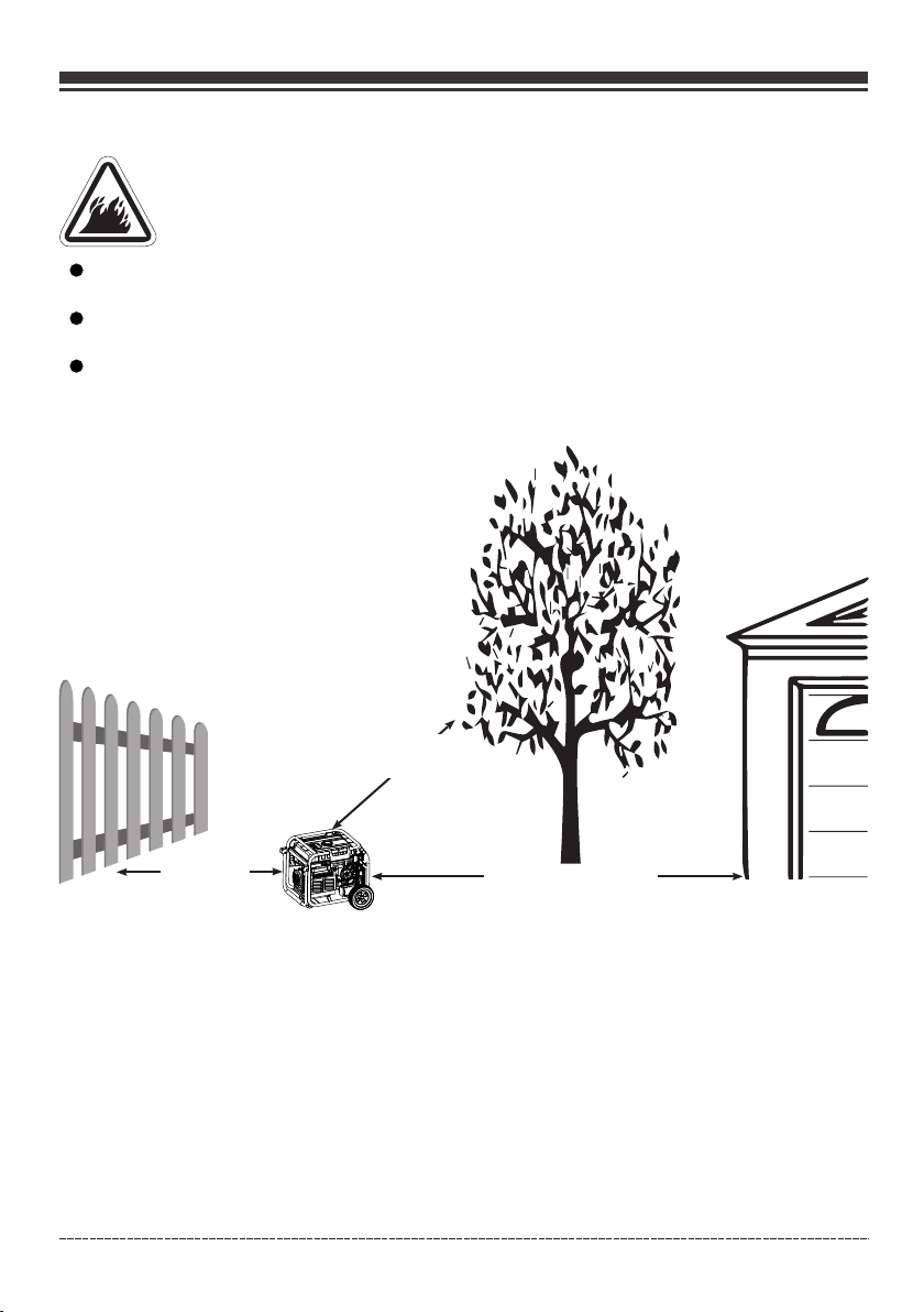
WARNING! Exhaust heat/gases could ignite combustibles, structures or damage fuel
tank causing a fire, resulting in death or serious injury.
Keep port able generator at l east 5 ft. (1.5m) fro m any structure , tr ees or vegetati on over 12
in. (30 cm) i n height.
Select an o utdoor site that is d ry and protected fr om the weather. D o no t move portable
generat or indoors to prote ct it from the weathe r.
Do not loca te the portable gen erator under a deck o r other similar s tr ucture that may
confine h eat and airflow.
5 ft.(1.5m)
min.
5 ft.(1.5m)
min.
Engli sh Cu stome r Servi ce: 1-8 44-FI RMAN1
20 ft.(6m)mi n.
11
Page 13
OPERATION
2, Oil and Gasoline / LPG
Add Engine Oil
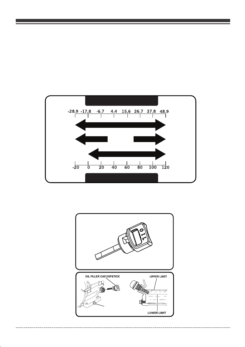
We recommend using FIRMAN SAE 10W-30 API SJ oil for best performance. Other high-quality
detergent oils (API SJ or higher) are acceptable. Do not use special additives. Ambient temperature
determines the proper oil viscosity for the engine. Use the chart to select the proper oil for the
outdoor temperature range expected.
NOT ICE Do not attempt to crank or start the engine before it has been properly filled with the
recommended type and amount of oil. Damage due to operation with no oil will void your warranty.
Degrees Celsiusº(Outside)
Full Synthetic 5W-30
5W-30 10W-40
10W-30
Degrees Fahrenheitº(Outside)
1.Place g enerator on a flat, l evel surface.
2.Clean a rea around oil fill a nd remove yellow oi l fill cap/dips ti ck.
3.Wipe di pstick clean.
H
L
(H)
DRA IN PLUG
(L)
Engli sh Cu stome r Servi ce: 1-8 44-FI RMAN1
12
Page 14
OPERATION
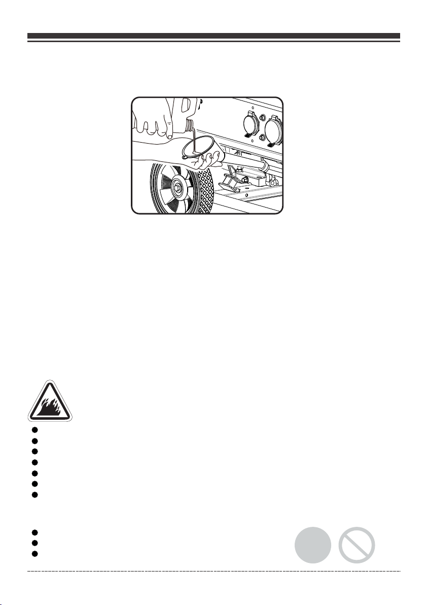
4. Us ing oil funnel, slowly pour contents of provided oil bo ttle into oil fill opening until oil reaches
upper limit "H" mark on the dipstick. Be careful not to overf ill. Overfilling could cause engine
starting problems or engin e damage.
5.Repla ce oil fill cap/dip stick and fully tig hten.
6.Oil lev el should be checke d prior to each use or at l east every 8 hour s of operation. Kee p oil
level mai ntained.
Low Oil Shutdown
The portable generator is equipped with a low oil shutdown. If the oil level drops below the
minimum required level, a sensor will activate an internal switch stopping the engine. If the
engine shuts off and the oil level is within specifications, check to see if generator is sitting at an
angle. Place portable generator on an even surface to correct this. If engine fails to start, the oil
level may not be high enough to deactivate the internal low oil level switch. Make sure the sump is
completely full of oil to the upper limit (H). Do not operate engine until oil level issue is corrected.
Contact Firman customer service.
Add Gasoline
WARNING! Fuel and its vapors are extremely flammable which could cause burns or fire
resulting in death or serious injury.
Turn gene rator engine OFF an d let it cool at least 2 mi nutes before re moving fuel cap.
Do Not refu el or move generato r when engine is runn ing.
Move gene rator outdoors pr ior to adding or drai ning fuel
Keep fuel a way from any igniti on sources.
Do not over fill tank, allow sp ace for fuel expans ion.
If any fuel s pills, wait until i t evaporates befo re starting eng in e
Check and r eplace fuel lines , tank, cap, and fitt ings prior to eac h use if any damage or le aks
are found .
Fuel must m eet these require ments:
Clean, fr esh, unleaded gas oline with a minimu m of 87 octane.
For high al titude use, see Ope ration at High Alti tude.
Gasolin e with no more than 10% e thanol is accepta ble.
Engli sh Cu stome r Servi ce: 1-8 44-FI RMAN1
13
E10
E15
Page 15
OPERATION
NO TI CE Do n ot mix oil in gasolin e or modify engine to r un on alternate fue ls not described in t his
manual. U se of unapproved fu els could damage en gine and will not b e covered under war ranty.
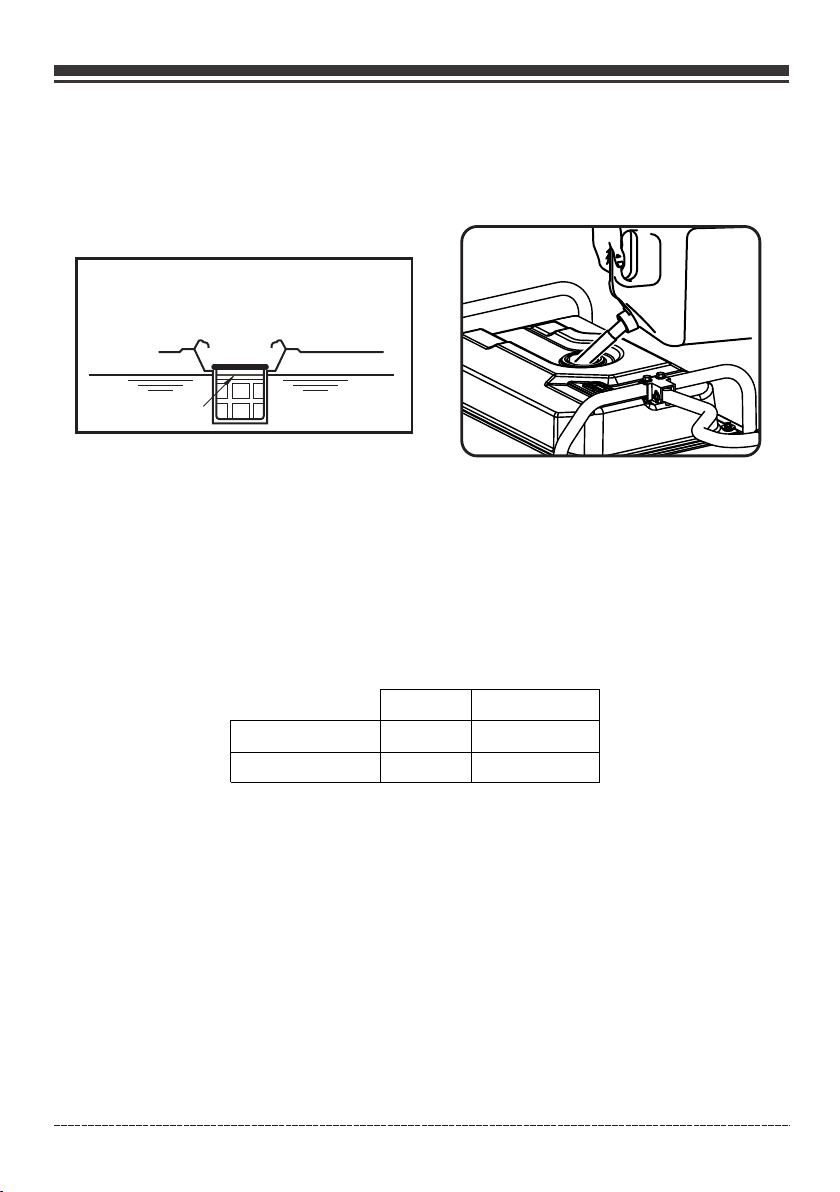
1. Clean ar ea around fuel fill c ap, remove cap.
2. Slowly a dd unleaded fuel to f uel tank. Be carefu l not to fill above t he RED fuel level ind icator.
This allo ws adequate space f or fuel expansion .
Red Line Indicator
3. Install fuel ca p and let any spill ed f uel evaporate b efore starting en gine.
Operation at High Altitude
At altitudes over 5,000 feet(1524 meters), a minimum 85 octane gasoline is acceptable.
Engine power and generator output will be reduced approximately 3.5% for every 1000 feet (305 m)
of elevation above sea level. High altitude may cause hard starting, increased fuel consumption
and sparkplug fouling. To operate at high altitudes FIRMAN can provide a high altitude carburetor
main jet. The alternative main jet and installation instructions can be obtained by contacting
Customer Support. Installation instructions are also available in the Technical Bulletin area of the
FIRMAN website www.firmanpowerequipment.com.
439cc
Altitud e main jet 1
Altitud e main jet 2
NO TI CE Ope ration using an alternative main je t at elevations lower than the rec om mended
minimum a ltitude can damag e the engine. For ope ration at lower e le vations, the st andard main
jet supplied must be used. Operating the engi ne with the wro ng main jet m ay increas e exhaus t
emissio ns, fuel consumpt ion and reduce perf ormance.
3807170 04
3807170 05
Altitude
3000-60 00Feet
6000-80 00Feet
Operation at High Ambient conditions
Your Firman Power Equipment product is designed and rated for continuous operation at ambient
temperatures up to 104°F (40°C). The generator may be operated at temperatures ranging from
5°F(-15°C) to 122°F(50°C) for short periods. If the generator is exposed to temperatures outside
this range during storage, the generator should be brought back within this range before
oper ation. W hen o p erated above 7 7°F(25 °C) t h e r e m ay b e a d ecreas e in power .
Maximum wattage and current are subject to and limited by such factors as ambient temperature,
altitude, engine conditions etc.
Engli sh Cu stome r Servi ce: 1-8 44-FI RMAN1
14
Page 16
OPERATION
Connecting LPG Fuel
WARNING ! Liquid Petroleu m gas (LPG) is extrem ely flammable w hi ch could cause
burns or fi re resulting in dea th or serious injur y.
The fuel su pply line must alwa ys be shut off when the e ngine is not runn ing. Failure to shu t
off fuel ma y allow fuel to leak at t he generator.
Do not plac e the LPG sources in th e path of muffler out let or near any ign ition source.
Keep a fire e xtinguisher nea r the generator all t he time.
Do not use or s tore LPG portable s ources not in use nea r generator or in a b ui lding, garage
or enclos ed area.
All LPG sup ply/ piping lines m ust be installed by a q ualified plum ber.
If you smel l gas, close off all ga s sources and conta ct a qualified pl umber to inspect an d
repair th e LPG .
Prior to ea ch days first use spr ay a soapy water solu tion on LPG fuel co nnections to chec k
for leaks .
Never use a g as container, LPG c onnector hose or LP G cylinder that a pp ears to be damage d.
Do not conn ect or disconnect t he LPG source in an enc losed area.
LPG is heav ier than air and can ac cumulate in confi ned / low spaces if t here is a leak.
NO TIC E If a fuel supp ly co nnection is necessary it must be installed in accordance with all local
codes or regulations, or in the absence of local codes or regulatio ns, in accordance with the
Natio nal Fuel G as Code ( NFPA 54/ANSI Z223.1) an d CSA B149 .1 (Natural Gas and Propane
Insta llation Code), as applicable.If poss ible the fuel supply connection should be clos e to the
outdo or operating location. This wil l reduce th e cost of the f lexible fuel run. An approved fle xible
fuel line must be installed between the generator LPG Hose C onnector (Inlet ) and the fuel
suppl y connection. In no case should this informat ion be interp reted to conflict with any loca l,
state , or nation al code. If in doubt, always follow local code s.
LPG
Always ke ep the LPG cylinder i n an upright positi on.
Use only DO T LPG cylinders in va por service with ty pe 1, right hand AC ME threads. Verif y the
re-qual ification date on t he cylinder has not e xpired.
All new cyl inders must be purg ed of air and moistur e prior to fillin g. The purging proc ess
should be d one by your propane g as supplier.
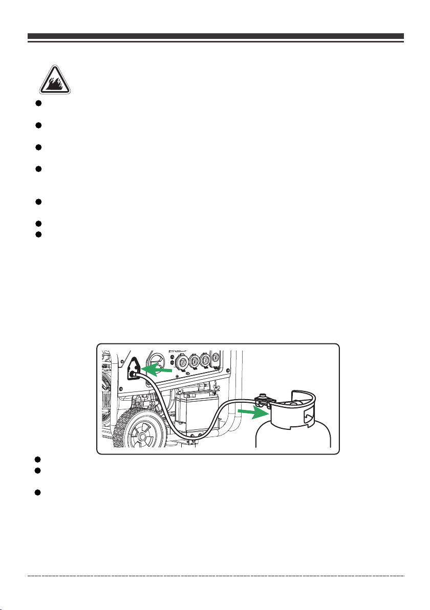
Attach the LPG regulator hose assembly (included) to the LPG hose connector (inlet) on the control
panel of the generator. Tighten the nut with a 19 mm or adjustable wrench. Remove the safety plug
or cap from the LPG cylinder valve. Attach the LPG regulator to the cylinder valve. Do not use a
wrench to tighten LPG cylinder nut. Tighten the nut by hand clockwise to a positive stop. Using a
wrench may damage LPG cylinder components.
Engli sh Cu stome r Servi ce: 1-8 44-FI RMAN1
15
Page 17
OPERATION
Indicator light - Battery Power Saving Mode
This generator is equipped with an electronic module which consumes battery power. When the
main fuel selector switch is turned to the GAS or LPG position, the indicator light will turn
RED for up to 4 minutes (before going off). Starting the engine successfully anytime during the 4
minutes will turn the indicator light GREEN. If portable generator is not started during this
4-minute period the portable generator will switch to Battery Power Saving Mode to conserve
battery life.
NO TI CE Yo ur p ortable gener ator is equipped wi th an internal batt ery charger that wi ll properly
charge th e battery only when t he engine is runnin g.
The generator cannot be started in Battery Power Saving Mode. Turn main fuel selector switch to
the off position and back to the GAS or LPG position to reset the RED indicator 4-minute
electronic module.
3. Starting the Generator on Gasoline
1. Before starting the generator, check for loose or missing parts and for any damage which may
have occurred during shipment. Ensure spark plug, muffler, fuel cap, and air cleaner are all in place.
2. Operate portable generator only outdoors and downwind at least 20 ft. (6 m) from occupied
spaces with exhaust pointed away to reduce the risk of carbon monoxide accumulating.
3. If connected ma ke sure the LPG cyl in der knob is fully c losed or disconne cted.
4. Turn the main fue l selector swit ch t o “GAS” positio n.
NO TI CE Wh en the main fuel sele ctor switch is turn ed to the GAS positio n, the indicator li ght will
turn RED fo r up to 4 minutes (befo re going off). Star ting the engine s uc cessfully any time during
the 4 minut es will turn the indi cator light GREEN . See Indicator l ig ht-Battery Po wer Saving
Mode sect ion for more inform ation.
Engli sh Cu stome r Servi ce: 1-8 44-FI RMAN1
16
Page 18
OPERATION
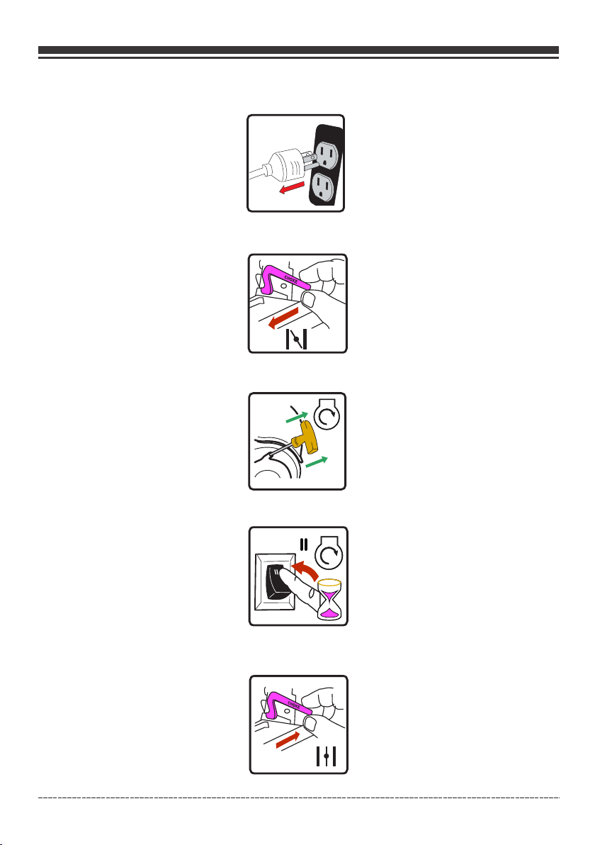
5. Discon nect all electric al loads from the gen erator. Never s tart or stop the gene rator with
electri cal devices plugg ed in.
6. Move choke lever located on engine to “START” position. You do not need to choke a warm engine.
(For electric start move to step (8))
7. For reco il start only - Pull th e starter cord slow ly until resist ance is felt and then p ull rapidly to
start eng ine.
8. For elec tric start only - Fli p the engine switch t o the START (ll) po sition for a few seco nds and
then rele ase.
3 sec.
9. Do not ove r-choke. As soon as e ngine starts and wa rms up, slowly mo ve the choke lever to t he
RUN posit ion.
Engli sh Cu stome r Servi ce: 1-8 44-FI RMAN1
17
Page 19
OPERATION
10. Allow p ortable generat or to run at no load for a fe w minutes to stab ilize before plug ging in
any elect rical devices.
NO TI CE If e ngine starts but fa ils to run, or if porta ble generator shu ts down during oper ation,
check oil l evel. See Low Oil Shu tdown section for m ore informati on .
4. Starting the Generator on LPG
1. Before starting the generator, check for loose or missing parts and for any damage which may
have occurred during shipment. Ensure spark plug, muffler, fuel cap, and air cleaner are all in place.
2. Operate portable generator only outdoors and downwind at least 20 ft. (6 m) from occupied
spaces with exhaust pointed away to reduce the risk of carbon monoxide accumulating.
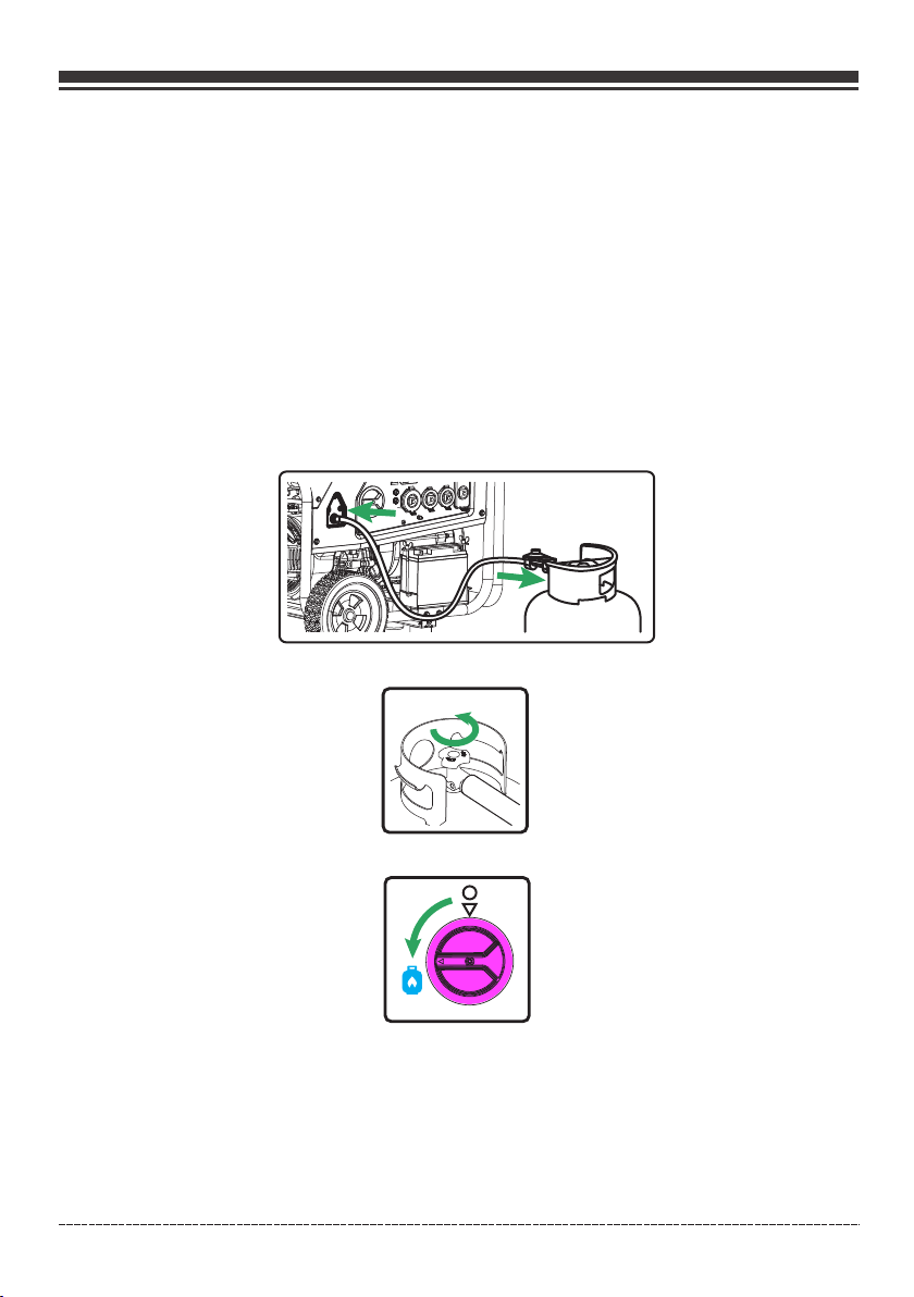
3. Co nnect the LPG hose with regulato r to both LPG cyli nder and portable gener ator LPG Hose
Connector (inlet).
LPG
4. Fully op en the LPG cylinder k nob.
5. Turn the m ain fuel selector s witch to LPG positi on.
NO TI CE Wh en t he main fuel sele ctor switch is turn ed to the LPG positio n, the indicator li ght
will turn R ED for up to 4 minutes (b efore going off). S tarting the eng ine successfull y anytime
during th e 4 minutes will turn t he indicator ligh t GREEN.
See Indic ator light-Batt ery Power Saving Mo de section for mo re i nformation.
Engli sh Cu stome r Servi ce: 1-8 44-FI RMAN1
18
Page 20
OPERATION
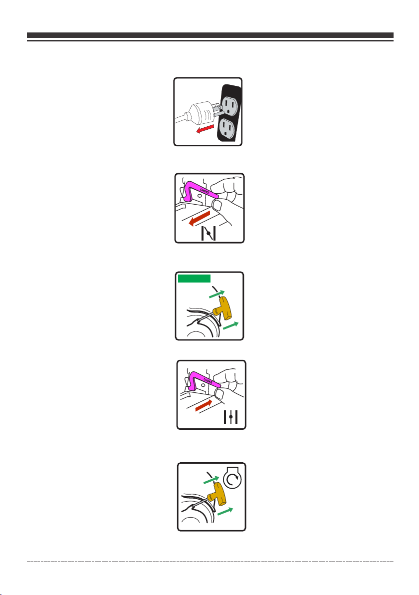
6. Discon nect all electric al loads from the gen erator. Never s ta rt or stop the gene rator with
electri cal devices plugg ed in.
7. Move cho ke lever located on e ngine to “START” po sition.
(For elec tric start move to st ep (11))
8. For reco il start only - PULL- TO-PRIME Pull the s tarter cord 1-2 t im es. Pull slowly u ntil resistance
if felt and t hen pull rapidly.
1-2 T imes
9.For rec oil start only - Move t he choke lever to the “ RUN” position .
10. For rec oil start only - PULL -TO-RUN Pull the st arter cord slow ly until resistan ce if felt and pull
rapidly t o run the portable ge nerator.
If the engi ne fails to start in 1- 2 pulls with choke in t he RUN position , move choke lever to S TART
positio n and repeat the PULL -TO-PRIME step (8 ).
Engli sh Cu stome r Servi ce: 1-8 44-FI RMAN1
19
Page 21
OPERATION
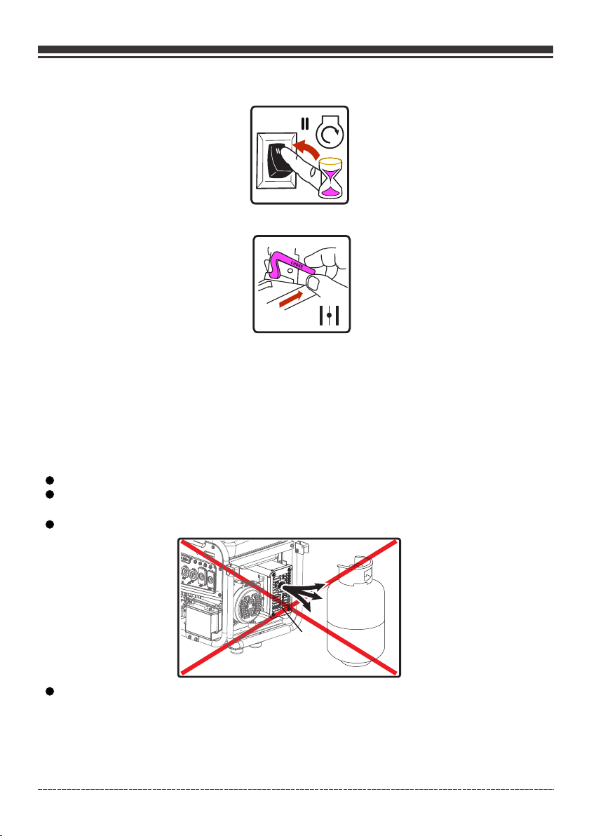
11. For ele ctric start only - Fl ip the engine switc h to the START (ll) p osition for a few sec onds and
then rele ase.
3sec.
12. For ele ctric start only - Mo ve the choke lever to t he RUN position .
13. Allow p ortable generat or to run at no load for a fe w minutes to stab ilize before plug ging in
any elect rical devices.
NO TI CE If e ng ine starts but fa ils to run, or if porta ble generator shu ts down during oper ation,
check oil l evel. See Lo w Oi l Shu td ow n section for m ore information .
NOT ICE Observing frost on LPG cylinder and regulator is common during operation and normally
is not an indication of a problem. In unusual situations this frost may eventually restrict the flow of
LPG gas to the generator resulting in deteriorating performance. In these rare situations it can be
helpful to:
Exchang ing fuel cylinder s to allow the first cy linder to warm up , repeating as nece ssary.
Placing t he LPG cylinder at th e end of the generato r near the handle , where engine fan
air flows o ut from the generat or. This air is sligh tly heated by air f lo wing over the eng ine.
Do not plac e the LPG cylinder in t he path of the muffle r exhaust outle t.
Muffler
The LPG cyl inder and compone nts can be temporar ily warmed by pou ring warm water ove r
them.
Engli sh Cu stome r Servi ce: 1-8 44-FI RMAN1
20
Page 22
OPERATION
5. Connecting Electrical Loads
This portable generator has been pretested and adjusted to handle its full capacity. The voltage is
regulated using an automatic voltage regulator (AVR) . Readjusting the AVR will void warranty.
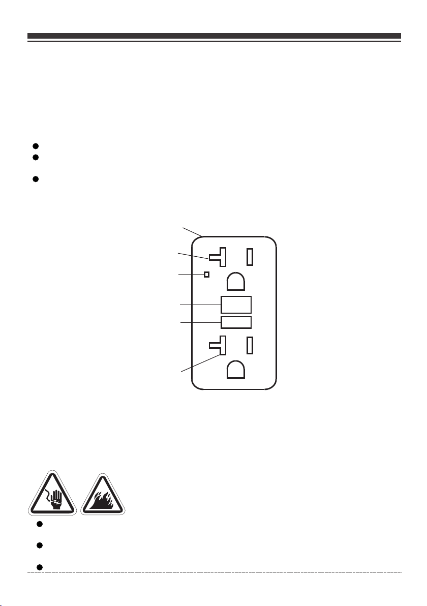
The duplex receptacle is equippe d with GFCI protection. The GFCI protects against electric shock
that may be caused if you become a path which electricity travels to reach earth. Even with a GFCI
you may feel a shock, but the GFCI cuts power quickly so an average per son should not suffer any
injury. Manual tes t GFCI while generator is running to verify internal contacts will function
Push the te st button. The rese t button will pop out , which should cu t power to outlet.
Press the r eset button until i t locks in the depres sed position. I f the GFCI does not res et as
describ ed do not use the recep tacles. Call Firm an customer ser vi ce.
If GFCI tri ps while in use, rese t and test the outlet . Electric cord s la ying on the groun d with
worn insu lation may trip the G FCI, only use cords i n good conditio n.
Receptacle
Outlet
LED Indicator Light
RESET BUTTON
TEST BUTTON
TEST MONTHLY
RESET
TEST
FOLLOW DIRECTIONS
Outlet
SELF-TEST OPERATION
In additi on to the manual test / r eset feature the GF CI receptacle t es ts itself perio dically to
confirm t he GFCI electroni cs are functional . The indicator l ig ht will be solid gr een when the
GFCI is pow ered from the gener ator and working co rrectly.
Self-test indications : If the indicator li ght is solid orange o r flashing red a pr ob lem may exist.
Press the T EST button to trip th e GFCI. If unable to re set, replace th e GFCI.
WARNING ! Generator volta ge could cause elec trical shock or b ur n
resulti ng in death or seriou s injury.
Damaged o r overloaded exte nsion cords could o verheat, arc, a nd burn resulting d eath or
serious i njury.
Use a groun d fault circuit int errupter (GFCI) i n any damp or highl y conductive area , such as
metal dec king.
Do not touc h bare wires or recep tacles.
Engli sh Cu stome r Servi ce: 1-8 44-FI RMAN1
21
Page 23
OPERATION
Do not use generator with electrical cords which are worn, frayed, bare or otherwise damaged.
Do not operate generator in the rain or wet weather.
Do not run indoors to avoid wet conditions.
Do not handle generator or electrical cords while standing in water, while barefoot, or while
hands or feet are wet.
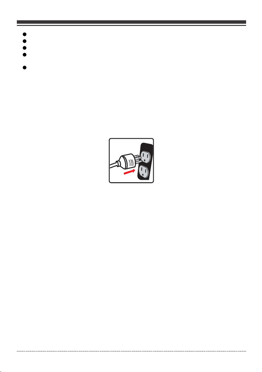
Use listed transfer switch to prevent backfeed by isolating generator from electric utility
workers.
1.Ensur e circuit breaker o n control panel is in t he closed (on) po si tion.
2. Start th e generator with no e lectrical load at tached.
3. Allow th e engine to run for sev eral minutes to sta bilize.
4. Plug in an d turn on the first ite m. It is best to attach t he item with the la rgest load first.
5. Allow th e engine to stabili ze.
6. Plug in an d turn on the next item .
7. Allow th e engine to stabili ze.
8. Repeat s teps 5-6 for each add itional item.
Surge Protection
There is a remote chance that voltage fluctuations may impair the proper functioning of some
sensitive electronic equipment. Electronic devices, including computers and many programmable
appliances may use components that are designed to operate within a narrow voltage range and
may be affected by the portable generator’s momentary voltage fluctuations. While there is no
way to prevent all voltage fluctuations, you can take steps to protect your sensitive electronic
equipment. Install a plug-in surge suppressor on the receptacles feeding your sensitive equipment.
Surge suppressors come in single or multi-outlet styles. They are designed to protect against short
duration voltage fluctuations.
Engli sh Cu stome r Servi ce: 1-8 44-FI RMAN1
22
Page 24
OPERATION
CO Alert
TM
Carbon Monoxide (CO) Shutdown System
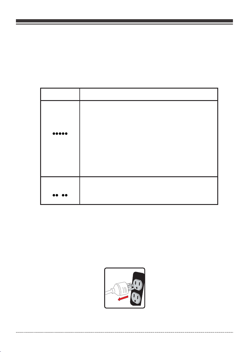
CO Alert au tomatically shu ts down the engine wh en harmful leve ls o f carbon monoxi de
accumul ate around the gene rator or a CO Alert fau lt occurs. Afte r shutdown, the CO Al ert
indicat or light will blink f or at least five minu tes per the chart b el ow.
CO Alert DO ES NOT replace carb on monoxide alarm s.
Install b attery-powere d carbon monoxide a larm(s) in your h ome. Don’t run gene rator in enclosed
areas.
Color
Red
Yellow
Carbon mo noxide accumula ted around genera tor. Prior
to restar t move generator to a n open, outdoor are a
downwin d and at least 20 ft. (6 m) f rom occupied spac es
with exha ust pointed away. A ir out premises (op en
windows a nd doors) before re occupying prope rty.
Automat ic shutoff is an indi cation generato r was
imprope rly located.
If you star t to feel sick, dizzy , weak, or your homes c arbon
monoxid e alar m soun ds while using th is produc t, get to
fresh air right away. Call emergency services . You may
have carb on monoxide poiso ning.
CO Alert fa ult occured*.
See FIRMA N authorized serv ice dealer.
Description
*Yellow light will blink for five seconds at the startup of generator to show CO ALERT is functioning
properly.
6. Stopping the generator
1. Turn off a nd remove all elect rical loads.
Never sto p the generator wit h electrical devi ces plugged in an d tu rned on.
Never sto p the engine by movin g the choke to the star t position.
Let the gen erator run at no-lo ad for one minute to st abilize inter na l temperature s of the engine
and gener ator.
Engli sh Cu stome r Servi ce: 1-8 44-FI RMAN1
23
Page 25
OPERATION
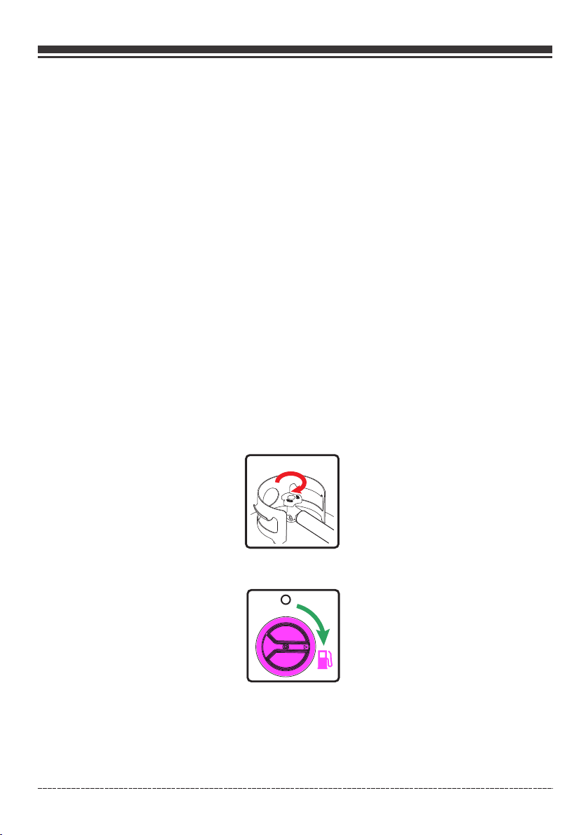
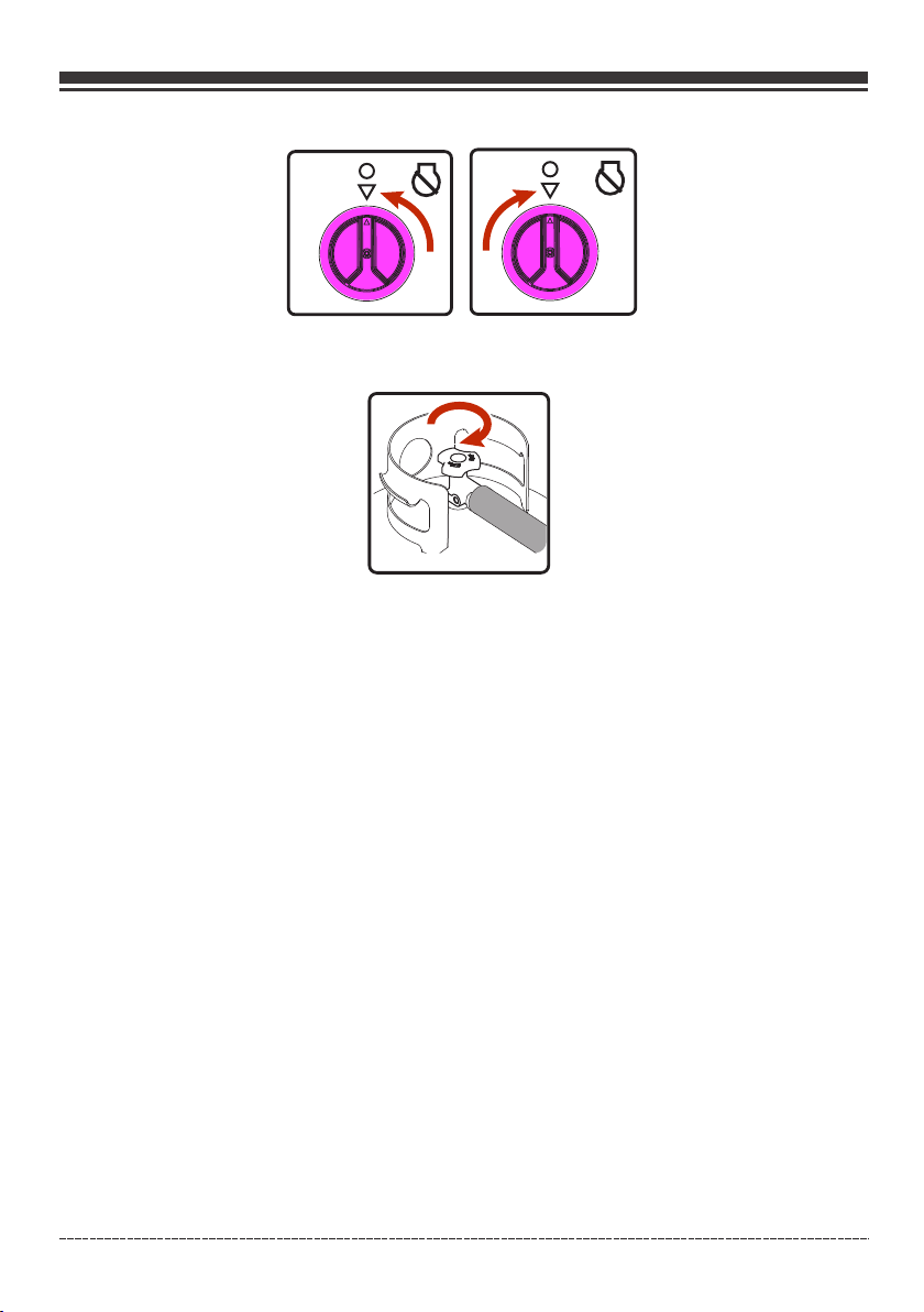
2. Turn the m ain fuel selector s witch to OFF (O) posi tion.
GAS LPG
3. Fully cl ose the LPG cylinde r knob .
If a cover is used, do not install until unit has cooled.
NOT ICE Disconnect the LPG cylinder from the generator during transportation.
Engli sh Cu stome r Servi ce: 1-8 44-FI RMAN1
24
Page 26
Maintenance - Storage
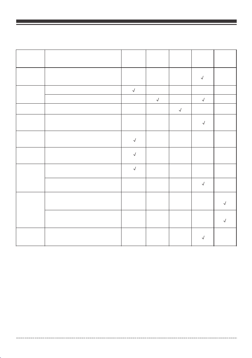
MAINTENANCE SCHEDULE
ITEM NOTES
Daily(Before
operation)
Initial
25 hours
Every
50 hours
Every
100 hours
(or annual)
Every
250 hours
Spark Plug
Engine Oil
Air Filter
Fuel
Fuel Line
LPG Regulator
/Hose Assy.
Exhaust
System
Engine
Fittings/
Fasteners
Check condition. Adjust gap
and clean. Replace if necessary.
Check oil level.
Replace.
Clean, replace if necessary.
Clean fuel tank strainer.
Replace if necessary.
Check fuel hose for cracks or other
damage. Replace if necessary.
Check for damage and leaks.
Replace if necessary.
Check for leakage. Retighten or
replace gasket if necessary.
Check spark arrester screen.
Clean/Replace if necessary.
Check adjust valve clearance.
Clean combustion chamber.
Check. Replace if necessary.
*
*
To be perfo rmed by knowledga ble/experienc ed owner or by auth orized service ce nter.
*
General Recommendations
Regular m aintenance will i mprove the perfor mance and exten d th e life of the gener ator. See any
authori zed dealer for serv ice.
The gener ator's warranty d oes not cover items t hat have been sub je cted to operato r abuse or
neglige nce. To receive ful l value from the warr anty, the opera to r must maintain t he generator as
instruc ted in this manual.
Some adju stments will need t o be made periodica lly to properly m aintain your gene rator.
All servi ce and adjustment s should be made at lea st once each seas on. Follow the requ irements
in the main tenanc shedule ch art above.
NO TI CE On ce a year you should cl ean or replace the sp ark plug and replac e the air filter. New
spark plu gs and clean air filt er assure proper fu el-air mixtur e an d help your engin e run at peak
perform ance and last longe r.
Engli sh Cu stome r Servi ce: 1-8 44-FI RMAN1
25
Page 27
DRAIN P LUG
Maintenance - Storage
When Transporting Generator
Transpo rt with fuel tank EMP TY or with main fuel va lve in OFF positi on.
Do not tip ge nerator at an angle w hich causes fuel to s pill.
Disconn ect LPG fuel hose and s ecurely stow away .
ENGINE MAINTENANCE
To prevent accidental starting, remove and ground spark plug wire before performing any service.
Change Engine Oil
Change en gine oil every 100 ho urs. (for a new engin e, change oil aft er 25 hours.)
If you are us ing your generato r under extremely d irty or dusty con ditions, or in extr emely hot
weather c hange the oil more of ten.
CAUTI ON! Avoid p rolonged or repeated skin contact with used motor oil . Used moto r oil has bee n
shown to cause skin canc er in certain la boratory animals. Thoroughly wash exposed areas with
soap and water.
KEEP OUT OF REACH OF CHILDREN. DON’T POLLUTE. CONSERVE RESOURCES. RETURN USED OIL
TO COLLECTION CENTERS.
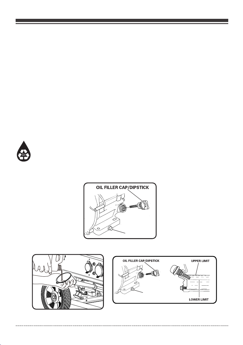
(a) On a leve l surface drain oil i nto a suitable cont ainer by removi ng the drain plug and t he oil
filler ca p while the engine is w arm.
(b) Reins tall the drain plug a nd fill the engine wi th oil until it rea ches the HIGH(H) le vel on the oil
filler di pstick.
(H)
DRA IN PLUG
(L)
NO TI CE We r ec ommend using FI RMAN SAE 10W-30 API S J oil for best perfor mance. Other high quality d etergent oils (AP I SJ or higher) are acc eptable. See Oi l an d Ga so li ne / L PG
Engli sh Cu stome r Servi ce: 1-8 44-FI RMAN1
26
Page 28
Maintenance - Storage
Air Filter Maintenance
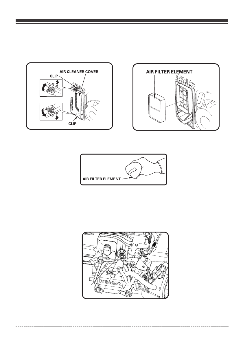
(a) Caref ully remove foam ai r filter element an d wash it with liqu id d etergent and wa ter only.
Squeeze d ry in a clean cloth.
(b) Saturate foam air filter element with clean engine oil and squeeze in a clean cloth to remove
excess oil.
( c) Reinst all clean or new air fi lter element.
Spark Plug Maintenance
Changin g the spark plug will h elp your engine sta rt easier and run a t pe ak performanc e.
(a) Remov e the spark plug boot .
(b) Remov e spark plug using pr ovided wrench.
A
B
A- Spark plug
B- Spark plug boot
Engli sh Cu stome r Servi ce: 1-8 44-FI RMAN1
27
Page 29
Maintenance - Storage
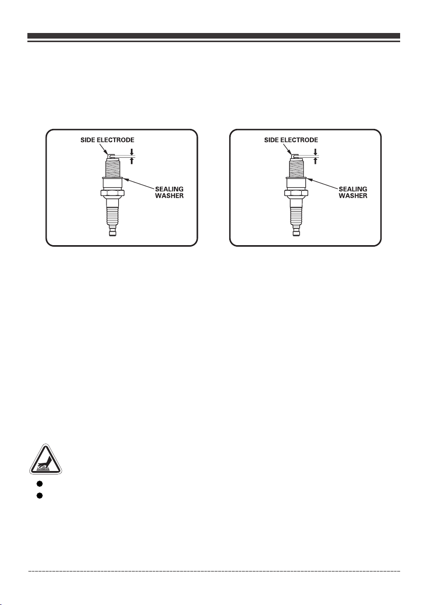
( c) Inspec t spark plug for dama ge and clean with a wir e brush before re installing. Rep lace if
damaged .
(d-1) For spark plug FIRMAN P/N 330723001 - Adjust the electrode gap to 0.020 - 0.024 in. ( 0.5 - 0.6 mm).
(d-2) For spark plug CHAMPION N9YC - Adjust the electrode gap to 0.028 - 0.031 in. ( 0.7 - 0.8 mm).
(e) Seat spark plug in position and thread by hand to prevent cross threading.
(f) Tighten plug with provided wrench and put the spark plug boot back on spark plug.
0.020-0.024 in.
(0.5-0.6mm)
SPARK PLU G: FIRMAN P/N 33072 3001 SPARK PL UG: CHAMPION N9YC
SPARK PLU G: FIRMAN P/N 33072 3001 or CHAMPION N9 YC
Maintenance Valve Clearance
- Intake: 0.004 - 0.006 in. (0.1 - 0.15 mm)
- Exhaust: 0.004 - 0.006 in. (0.1 - 0.15 mm)
Muffler and Spark Arrester
0.028-0.031 in.
(0.7-0.8mm)
WARNING! C on tact with muffl er area could cause b urns resulting in s erious injury.
Do not toug h hot parts.
It is a violation of California Public Resource Code, Section 4442, to use or operate the engine
on any forest-covered, brush-covered, or grass-covered land unless the exhaust system is
equipped with a spark arrester, as defined in Section 4442, maintained in effective working
order. Other states or federal jurisdictions may have similar laws, reference Federal
Regulation 36 CFR Part 261.52.
Engli sh Cu stome r Servi ce: 1-8 44-FI RMAN1
28
Page 30
Maintenance - Storage
Inspect Muffler and Spark Arrester
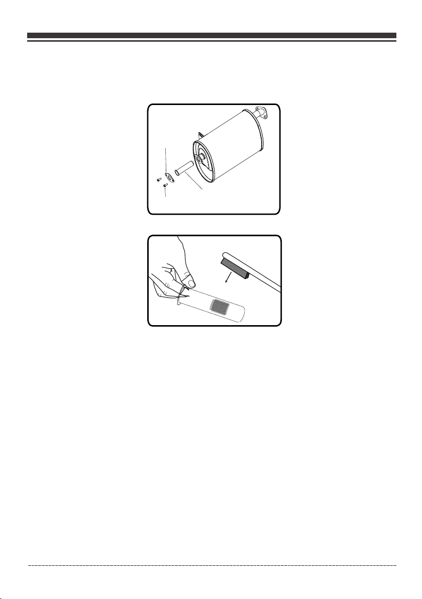
1. Inspect the muf fler for cracks , co rrosion, or oth er damage.
2. Remove the scre ws securing the s pa rk arrester in pl ace and the remove it f rom muffler.
Flange
Screw
3. Carefu lly remove the carb on deposits from th e spark arreste r sc reen with a wire br ush.
3. Replac e the spark arreste r if it is damaged. If re placement par ts a re required, ma ke sure to use
only FIRM AN original equip ment replacemen t parts.
4. Positi on the spark arrest er in the muffler and a ttach with the sc rews.
NO TI CE Fa il ure to clean or rep lace spark arrest er may result in decr eased engine perf ormance.
Spark arrester
screen
GENERATOR MAINTENANCE
Run the gen erator at least 30 mi nutes every month .
Make cert ain that the portab le generator is kep t clean and dry.
Do not expo se the unit to excess ive dust, dirt, moi sture or corros iv e vapors.
Do not inse rt any objects thro ugh cooling slots .
Before ea ch use inspect unde rneath the genera tor for signs of oi l or f uel. Clean any ac cumulated
debris. K eep area around muf fler free from any de bris. Use a soft br is tle brush to remo ve dirt or
caked on oi l. Use a damp cloth to cl ean all exterior su rfaces.
Engli sh Cu stome r Servi ce: 1-8 44-FI RMAN1
29
Page 31
Maintenance - Storage
Battery Replacement
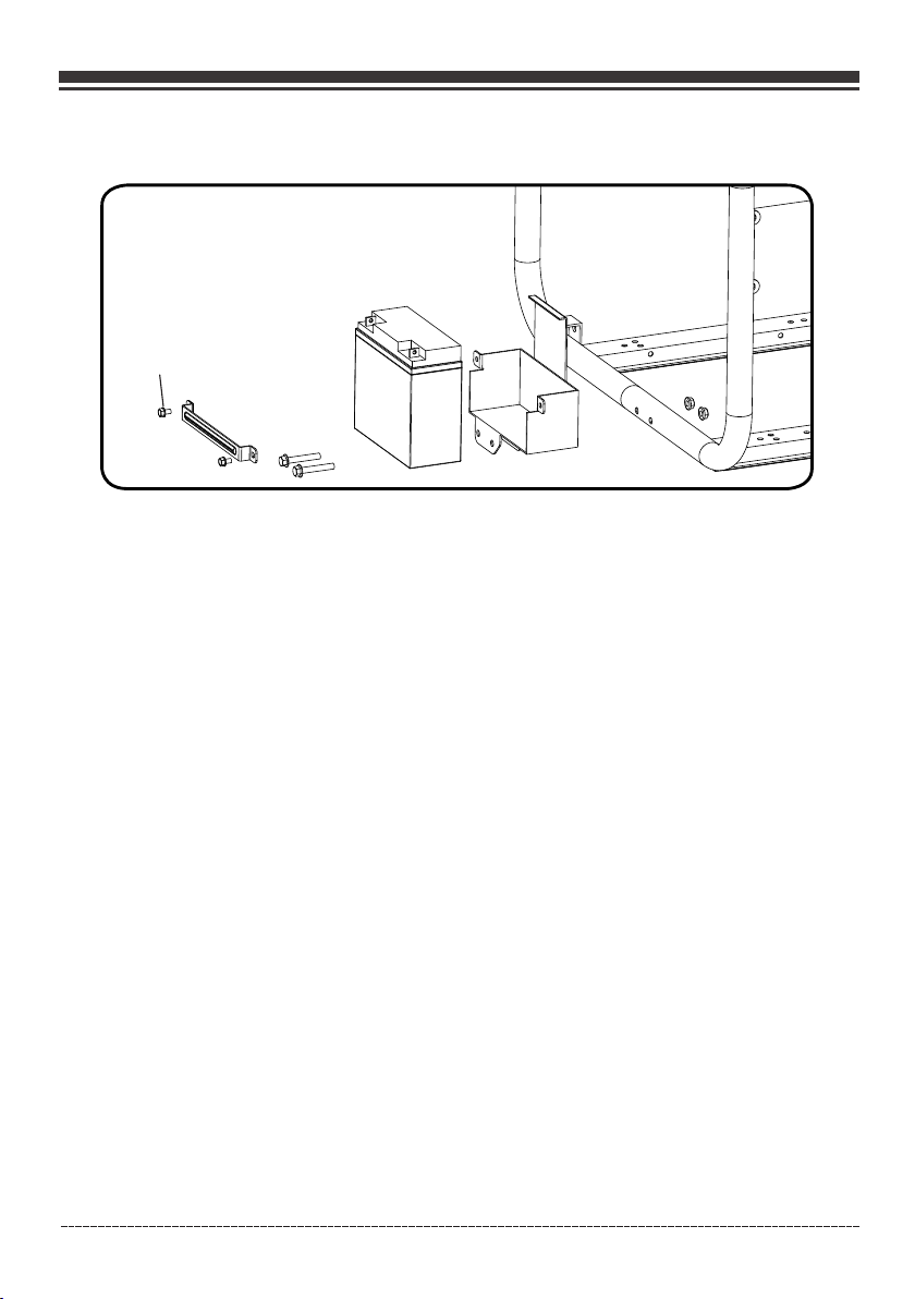
A(M6)
1. Remove t he spark plug boot fr om spark plug.
2. Remove t he nut and bolt from th e negative(-) pos t first, then the p ositive(+) post .
3. Loosen a nd remove the wing nu ts (A) on the battery h olding bracke t.
4. Remove t he battery and recy cle.
5. Instal l the new battery wit h the following spe cification:
12V seale d lead acid 15AH
LXWXH: 7. 09X2.95X6.5in ch(180X75X165 mm)
6. Connec t the red positive (+ ) battery cable to th e battery first .
7. Connec t the black negativ e (-) battery cable t o the battery sec ond.
8. Cover th e posts with boots pr ovided.
9. Instal l the spark plug boot o nto spark plug.
Battery Charging
The battery powers the starter motor and control module . Thi s porta ble g enerator is equipped
with a n automatic battery c harging circ uit. The battery will receive charging vol tage only w hen
the engine is r un ning. The battery will main tain a p roper charge if the porta ble generator is used
on a re gular basis (ab out once ever y two weeks). If it is use d less frequent ly, the batte ry should
be connecte d to a trick le c harger (not included) or batt ery maintainer (not inclu ded) to ke ep t he
battery p ro perly charged. If t he b at tery is not able to start the e ng ine, it can be started manu ally
only in the G AS position by pull ing the engine reco il cord. If the bat tery voltage is ext remely low,
the charging circui t may not be able to re-charge the battery. In this case, the battery must be
connect ed to a standard auto motive style batt ery charger for r e-charging befo re it can be used.
Engli sh Cu stome r Servi ce: 1-8 44-FI RMAN1
30
Page 32
Maintenance - Storage
Long Term Storage
It is important to prevent gum deposits from forming in essential fuel system components such
as the carburetor, fuel hoses or tank during storage. Alcohol-blended fuels (called gasohol, ethanol
or methanol) attract moisture, which leads to separation and formation of acids during storage.
Acidic gas can damage the fuel system of an engine while in storage.
When the generator set is being stored for more than one month, follow these instructions to avoid
engine problems:
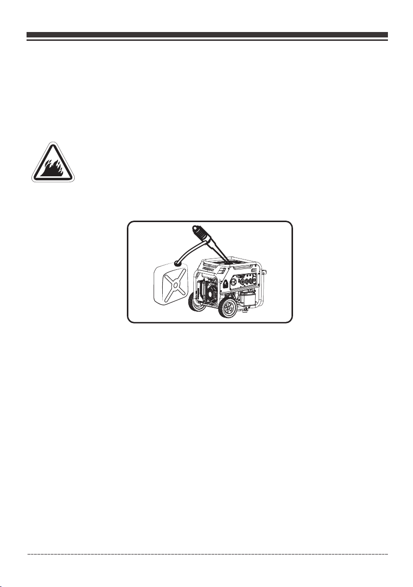
WARNING! F ue l and its vapors ar e extremely flamm able which could ca use burns
or fire res ulting in death or se rious injury.
Do not stor e fuel near any ignit ion sources.
When drai ning fuel move gene rator outdoors an d use a commercia lly available non -conductive
vacuum si phon. Fuel must be dr ained into an appro ved container .
1-Treat a ny stored fuel with f uel stabilizer.
2-When st oring generator w ith gasoline in fue l tank, operate t he e ngine for 5-10 mi nutes to
circula te treated fuel int o fuel lines and carb uretor before s hu tdown.
3- There is n o need to drain gasol ine from the genera tor fuel tank if fu el s tabilizer is ad ded.
4-FUEL ST ARVATION: If you el ect to drain fuel tan k move generato r ou tdoors. Once fu el tank is
drained t urn main fuel selec tor switch to GAS pos ition. Start an d run the portable ge nerator
outdoor s until engine stop s from lack of gasoli ne. This will dra in remaining gaso line from tank,
fuel line s, and carburetor .
5-Alway s turn main fuel sele ctor switch to OFF po sition prior to s torage.
6-Allow t he portable gener ator to cool before c leaning and sto rage.
7-Chang e oil .
8-Remov e spark plug boot and s park plug. Pour abo ut one teaspoon o f engine oil throug h the
spark plu g hole, then slowly p ull the recoil star ter several tim es to distribute th e oil in the
cylinde r. Reinstall the sp ark plug and attach t he spark plug boo t. Pull recoil slow ly until resistan ce
is felt. Th is will close the val ves so no moisture en ters the engine c ylinder.
9-Cover t he portable gener ator and store in a cle an, dry place out o f direct sunlight a nd away from
any ignit ion sources.
Any damag e or hazards caused b y using improper fu el, improperl y stored fuel, and/ or improperly
formula ted stabilizers , are not covered by ma nufacturer' s wa rranty.
Do not stor e gasoline from one s eason to another se ason.
Engli sh Cu stome r Servi ce: 1-8 44-FI RMAN1
31
Page 33

Troubleshooting – Specifications
Problem Cause Correction
Engine is running, but no
AC output is available.
Engine runs good at
no-load but “bogs down”
when loads are connected.
Engine will not start; starts
and runs rough or shuts
down when running.
1. Circuit breaker is open.
2. Fault in generator.
3. Poor connection or defective cord set.
4. Connected device is bad.
1. Short circuit in a connected load.
2. Engine speed is too slow.
3. Shorted generator circuit.
4. Clogged or dirty fuel filter.
1. Fuel selector switch set to OFF (O)
position.
2. The indi cator light is OFF or
flashin g red.
3. Low oil level.
4. Dirty air cleaner.
5. Out of gasoline.
6. Stale gasoline.
7. Spark plug wire not connected to
spark plug.
8. Bad spark plug.
9. Water in gasoline.
10. Flooded.
11. Excessively rich fuel mixture.
12. Clogged or dirty fuel filter.
13. Starting battery may have
insufficient charge.
14. Out of LP G. 14. Replace LPG cylinder.
15. LPG cyl inder knob is not ope n. 15. Fully open LPG cylinder knob .
16. Out of ba ttery power.
1. Reset circuit breaker.
2. Contact authorized service facility.
3. Check and repair.
4. Connect another device that is in
good condition.
1. Disconnect shorted electrical load.
2. Contact authorized service facility.
3. Contact authorized service facility.
4. Clean or replace fuel filter.
1. Set fuel selector switch to “GAS”
or “LPG” position.
2. Must have solid red indicator light
to be able to start the engine.
3. Fill crankcase to proper level or
place generator on level surface.
4. Clean or replace air cleaner.
5. Fill fuel tank with gasoline.
6. Drain fuel tank and carburetor; fill
with fresh gasoline.
7. Connect wire to spark plug.
8. Replace spark plug.
9. Drain gas tank and carburetor; fill
with fresh gasoline.
10. Wait 5 minutes and re-crank engine.
11. Contact authorized service facility.
12. Clean or replace fuel filter.
13. Check battery output and charge
battery as necessary.
16. Start E ngine in “GAS” posi tion.
Charge or r eplace battery.
1. Load is too high.
Engine lacks power.
Engine“hunts”or falters.
Engine shuts down when
running.
Engine shuts down and
yellow CO fault light
blinking.
For all oth er issues, contac t authorized deal er or Firman cust omer service.
Engli sh Cu stome r Servi ce: 1-8 44-FI RMAN1
2. Dirty air filter.
3. Clogged or dirty fuel filter.
4. Clogged spark arrester.
1. Carburetor is running too rich or too lean.
2. Clogged or dirty fuel filter.
1. Out of gasoline or LPG.
2. Dirty air cleaner.
3. Low oil level.
1. CO syste m fault
32
1. Don't Overload Generator
2. Replace air filter.
3. Clean or replace fuel filter.
4. Clean or replace spark arrester.
1. Contact authorized service facility.
2. Clean or replace fuel filter.
1. Fill fuel tank with gasoline or replace
LPG cylinder .
2. Clean or replace air cleaner.
3. Fill crankcase to proper level or place.
generator on level surface.
1. Contac t authorized FIRM AN
service f acility.
Page 34
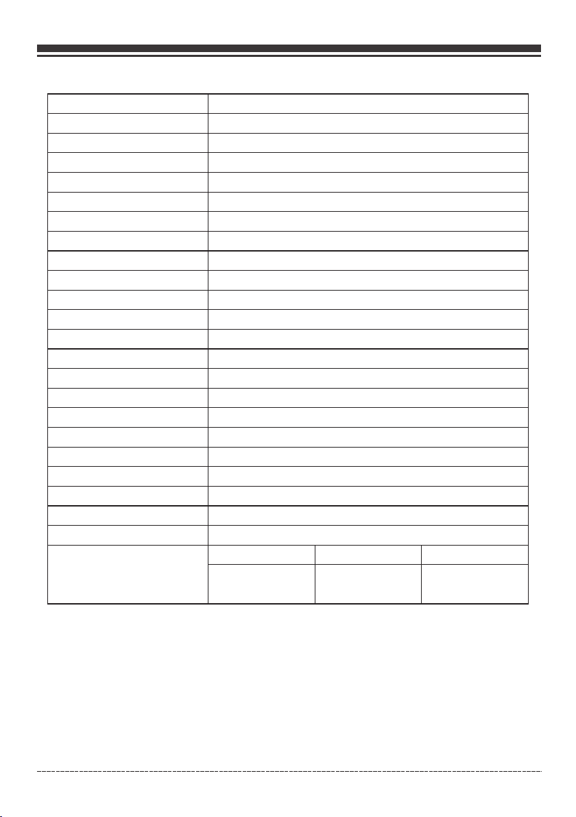
Troubleshooting – Specifications
SPECIFICATIONS
Model
Starting Watts
Running Watts*
Rated AC Voltage
Rated Fequency
Phase
Voltage Regulator
Power Factor
Alternator Type
Engine
Engine Type
Displacement
Low Oil Shutdown
Ignition System
Starting System
Fuel
Capacity Fuel Tank
Lubricating Oil Capacity
Carburetor Type
Air Cleaner
P.T.O. Shaft Rotation
Oil Type
AC Grounding System
LPG fuel consumption
No Load Half Load Full Load
3
15. 6ft /hr( 1.6L/ hr)
39,000 BTU/h (11,429 W)
10000(GASOLINE)/9050(LPG)
8000(GASOLINE)/7250(LPG)
Single Cylinder, 4-Stroke OHV Air Cooled
Breakless Ignition Type, Flywheel Magneto
Recoil/ Electric Start
Unleaded Automotive Gasoline/LPG
8.0 U.S. Gallons (30.3L)
Counter Clockwise (Facing P.T.O.)
See “Add Engine Oil” Section
Neutral Bonded To Frame
82,500 BTU/h (24,176 W) 136,500 BTU/h (40,000 W)
H08052
120/240V
60Hz
Single
AVR
1
Brushed
FIRMAN
439cc
Yes
37.2 oz (1.1L)
Float
Polyurethane Type
3
33f t /hr(3 .4L/h r)
3
54. 6ft /hr( 5.7L/ hr)
*Generator certified in accordance with CSA (Canadian Standards Association) standard C22.2No. 100-14,
Motors and Generators and complies with PGMA (Portable Generator Manufacturers’ Association) standard
ANSI/PGMA G300-2018, Safety and Performance of Portable Generators.
Engli sh Cu stome r Servi ce: 1-8 44-FI RMAN1
33
Page 35
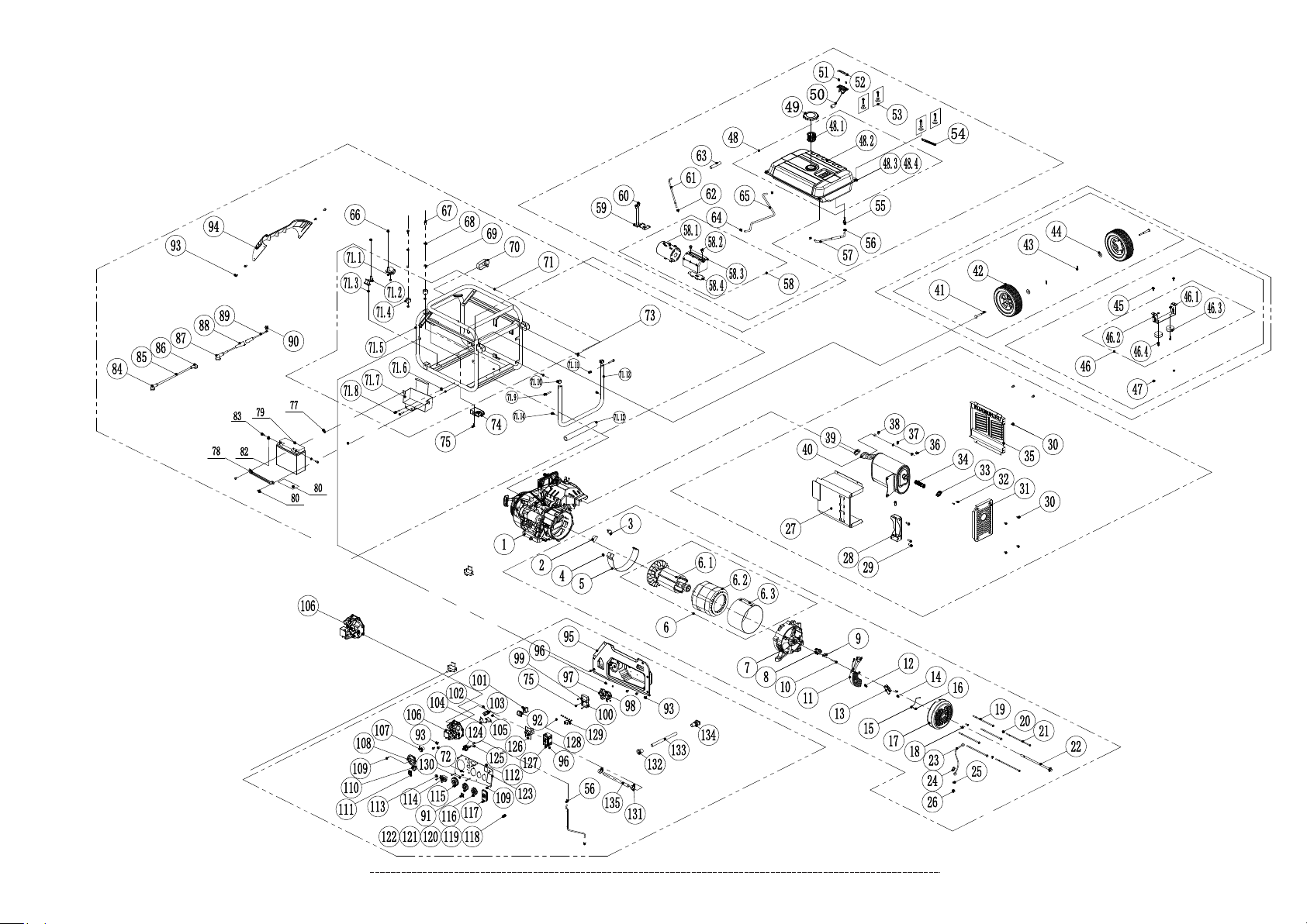
PARTS DIAGRAM AND PART LIST
H08052 PARTS DIAGRAM
Engli sh Cu stome r Servi ce: 1-8 44-FI RMAN1
34
Page 36
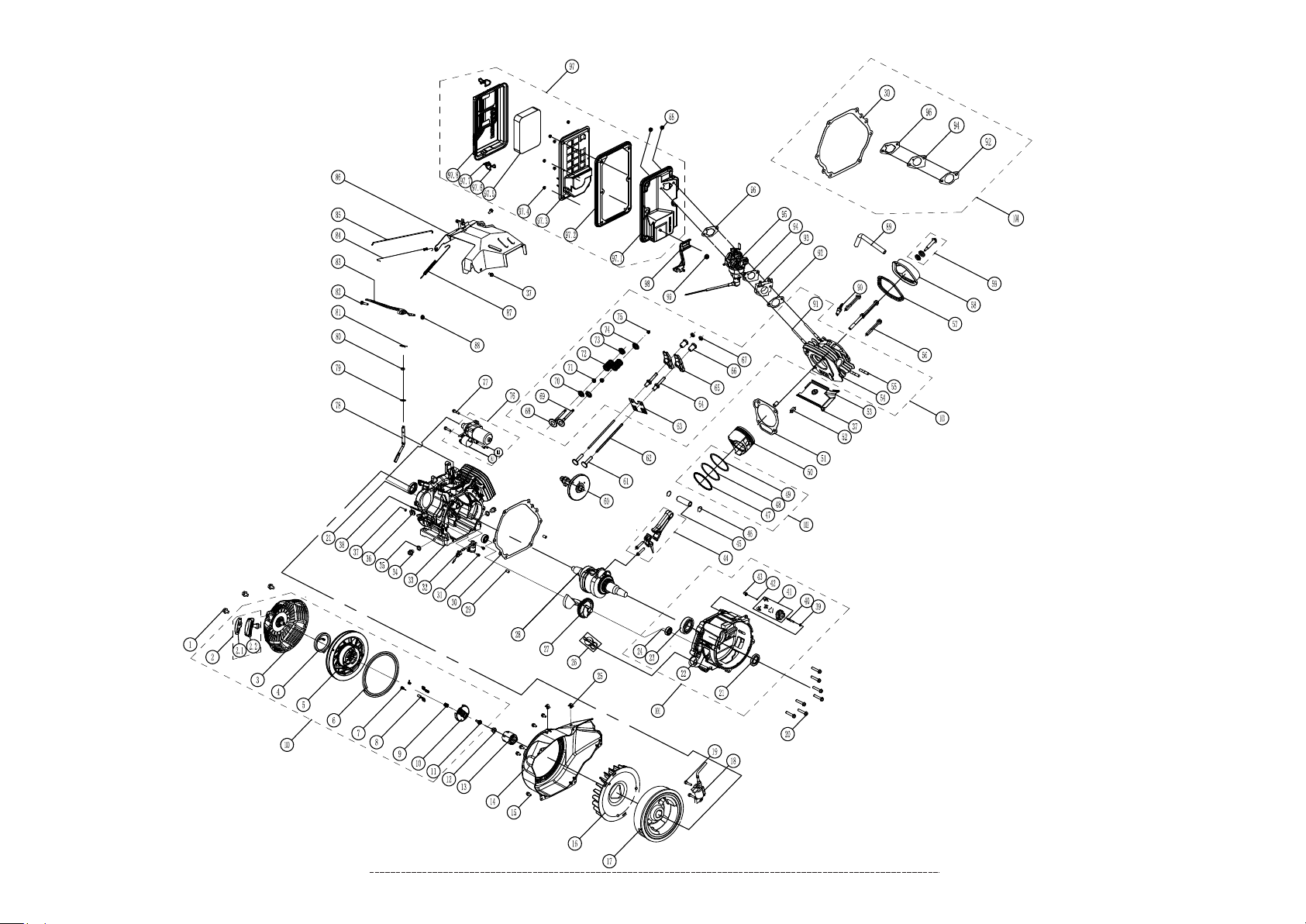
439cc DUAL FUEL ENGINE PARTS DIAGRAM
Engli sh Cu stome r Servi ce: 1-8 44-FI RMAN1
35
Page 37
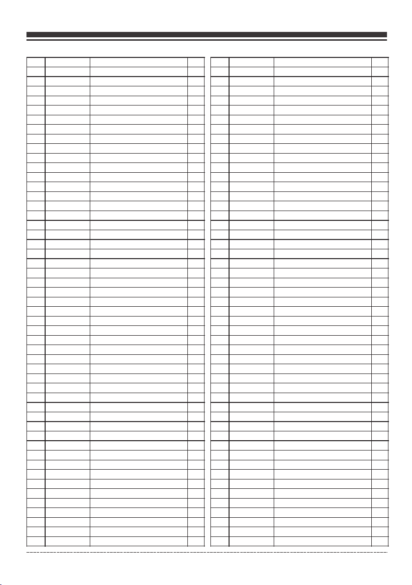
Parts Diagrams - Parts Lists - Wiring Diagram
H08052 Portable Generator
NO.
Part Number
1
3757183 00
2
3577135 01
3
3577135 24
4
3367135 28
5
3577135 73
6
3804135 01
6.1
3807135 35
6.2
3807135 36
6.3
3807135 03
7
3577135 06
8
3577135 07
9
3367135 25
10
3577135 63
11
3807135 04
12
3367135 19
13
3367135 23
14
3367135 20
15
3367135 22
16
3367135 19
17
3577135 09
18
3367183 09
19
3807135 06
20
3367135 77
21
3807135 07
22
3807135 08
23
3367135 14
24
3367183 01
25
3367135 16
26
3367135 17
27
3577135 23
28
3577135 15
29
3367135 31
30
3367183 02
31
3577135 16
32
3367135 38
33
3577135 17
34
3367135 36
35
3577135 18
36
3367135 34
37
3367135 09
38
3367135 33
39
3577135 20
40
3807135 38
41
3577135 35
42
3577135 92
43
3577135 36
44
3577135 14
45
3367135 59
46
3574135 06
46.1
3367183 14
Engli sh Cu stome r Servi ce: 1-8 44-FI RMAN1
Engine Su bassembly
Rubber Ca p B
Rubber Ca p A
Flange Bo lt M6×8
Generat or Wind Shield
Rotor And S tator Set
Rotor Ass y
Stator As sy
Stator Co ver
Generat or End Cover
Carbon Br ush Assembly
Carbon Br ush Holder
Bolt &was her Assemblies
AVR
Flange Bo lt M5×16
Termina l Block
Bolt M5×1 6
Ground Wi re
Flange Bo lt M5×16
Generat or End Cover Cap
Flange Bo lt M5×12
Flange Bo lt M6×200
Nut M5
Side Cove r Bolt M5×229
Flange Bo lt M10×285
Ground Wi re
Flange Bo lt M6×12
Externa l Star Washer Ø6
Nut M6
Protect or,muff.,back
Holder, muff
Flange Bo lt M8×20
Flange Bo lt M6×12
Protect or,Muff.,side
Screw&washer Assy M5×14
Holder, Spark Arrester
Arreste r,Spark
Protect or,Muff.,Fron t
Nut M8
Lock Wash er Ø8
Flat Wash er Ø8
Gskt.,e xt.
Muff.,a ssy.
Axle Comp
Wheel
Lock Pin
Washer Ø1 0
Flange. B olt M8×16
Support L eg Assembly
Nut M6
Description
Qty.
NO.
46.2
46.3
46.4
48.1
48.2
48.3
48.4
58.1
58.2
58.3
58.4
71.1
71.2
71.3
71.4
71.5
71.6
71.7
71.8
71.9
71.10
71.11
71.12
71.13
71.14
36
Part Number
3577135 38
3367135 57
3367135 61
47
3367135 58
48
3577135 79
3367138 06
3577137 11
3367135 42
3577136 00
49
3367135 49
50
3577135 78
51
3367135 46
52
3367135 47
53
3937130 18
54
3177135 77
55
3367138 07
56
3307135 08
57
3804270 05
58
3804283 00
3367136 37
3807130 03
3367136 36
3367136 39
59
3367136 38
60
3937130 16
61
3807135 33
62
3307135 09
63
3577135 46
64
3367135 40
65
3807135 32
66
3577135 31
67
3577135 84
68
3367135 09
69
3757183 01
70
3367136 91
71
3804170 06
3577135 32
3577135 33
3367183 18
3577135 85
3577135 83
3367135 58
3757150 02
3577135 27
3577135 27
3804270 06
3804170 08
3577135 97
3367138 41
3804270 08
1
1
1
1
1
1
1
1
1
1
1
1
1
1
2
1
2
1
1
1
2
4
2
2
1
1
1
1
4
1
1
4
7
1
2
1
1
1
2
2
2
1
1
2
2
2
2
2
1
2
Description
Support L eg
Rubber, S upport
Flange Bo lt M6×25
Nut M8
Fuel Tank A ssy.
Fuel Filt er, Wire Mesh
Fuel Tank
Grommet , Fuel Tank
Washer Ta nk Buffer
Fuel Cap
Fuel Gaug e Assy.
Screw M5× 10
Fuel Gaug e Display
Bolt M6×2 0
Clip
Tank Fitt ing With Filter
Clamp
Hose,fu el 1
Carbon Ca nister Assy
Carbon Ca nister
Flange Bo lt M6×6
Carbon Ca nister Shield
Carbon Ca nister Bracket
Carbon Ca nister Holder
Flange. B olt M8×16
Vapor Hos e 2
Clip (Ø8. 7×8)
Sleeve
Clamp Ø8× 6
Vapor Hos e 1
Nut M10
Flange Bo lt M8×35
Lock Wash er Ø8
Washer
Hose Hold er
Frame
Isolato r 2
Isolato r 1
Nut M8
Motor Mou nt
Frame
Nut M8
Battery H older
Flange. B olt M8×50
Flange. B olt M8×50
Plug
Nut M8
Handle
Red Boot
Cushion
Qty.
1
2
2
2
1
1
1
4
4
1
1
2
1
4
1
1
4
1
1
1
2
1
1
1
2
1
1
1
2
1
2
2
2
2
1
1
1
1
4
2
1
2
1
2
2
2
2
1
1
2
Page 38
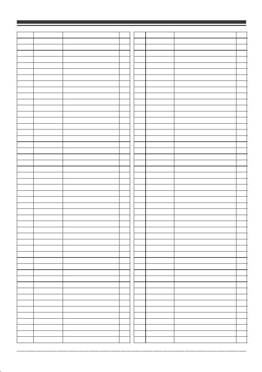
Parts Diagrams - Parts Lists - Wiring Diagram
NO.
72
73
74
75
76
77
78
79
80
81
82
83
84
85
86
87
88
89
90
91
92
93
94
95
96
97
98
99
100
101
102
103
104
105
106
107
108
109
110
111
112
113
114
115
116
117
118
119
120
121
Part Number
3367183 68
3757183 02
3924283 00
3367135 65
3804270 07
3367183 14
3937130 35
3577135 53
3367183 29
3757283 00
3367135 78
3577135 69
3367138 41
3577135 56
3367136 11
3367138 42
3367136 93
3577136 07
3367135 28
3807270 07
3927583 02
3367183 02
3577135 82
3577135 90
3367183 24
3367136 01
3367135 83
3367183 19
3367138 18
3807135 24
3804170 07
3367138 21
3367138 22
3367138 19
3754183 00
3367138 26
3367138 15
3307135 82
3367138 27
3367550 04
3367550 05
3367138 28
3577135 86
3367135 74
3367135 73
3577135 41
3577135 42
3577135 43
3367135 12
3367135 13
Description
Screw&washer M3×6
Flange Bolt M8×12
CO Module
Screw M5×14
Fuel Hose 2
Nut M6
Battery Pressure Plate
Battery
Flange. Bolt M6×15
Grommet
Nut M5
Screw&washer M5×10
Red Boot
Battery Red Cable +
Boot,Starter
Black Boot
Battery Cable(female 180mm)
Battery Cable(male 180mm)
Flange Bolt M6×8
Cover
Cover
Flange Bolt M6×12
Plastic Front Cover
Control Box
Nut M4
Receptacle L14-30R
Receptacle L5-30R
Control Module
Charger
Circuit Breaker 33A
Tapping Screw St2.9×28
Micro Switch 1
Micro Switch 2
Tapping Screw St2.9×19
Main Regulator Assy.
LPG Inlet Cover
Fuel Selector Switch
Screw&washer M4×14
Switch
Switch Cover
Circuit Breaker Cover
Indicator Light
Multi Meter
Outlet Cover TT-30R
Outlet Cover L5-30R
Outlet Cover 5-20R GFCI
Bolt M6×22
Nut M6
Lock Washer Ø6
Washer Ø6
Qty.
4
2
1
5
1
2
1
1
3
1
2
2
1
1
1
1
1
1
1
1
1
11
1
1
8
1
1
1
1
1
2
1
2
2
1
1
1
6
1
1
1
1
1
1
2
1
1
2
2
4
NO.
Part Number
122
123
124
125
126
127
128
129
3367550 02
130
131
132
133
134
135
3367135 16
3804170 05
3367138 24
3757183 20
3807135 18
3577135 88
3807135 26
3307135 94
3367138 35
3577135 45
3577135 46
3577135 48
3577135 91
Description
Externa l Star Washer Ø6
Control P anel Assy
Fuel Valv e Comp.
Screw&w asher Assy M4×8
Recepta cle 14-50R
5-20R Dup lex GFCI
Circuit B reaker Amp 30A
AC 20A Brea ker
Indicat or Light(CO)
Clamp
Grommet
Sleeve
Grommet
LPG Hose
Qty.
1
1
1
2
1
1
1
1
1
2
1
1
1
1
Engli sh Cu stome r Servi ce: 1-8 44-FI RMAN1
37
Page 39

Parts Diagrams - Parts Lists - Wiring Diagram
FIRMAN 439cc Dual Fuel Engine
NO.
Part Number
1
336718308
357723577
2
336728300
2.1
336728301
2.2
357723579
3
357723580
4
357723582
5
393723006
6
336723589
7
336723590
8
336723592
9
336723591
10
336723593
11
357723571
12
357723572
13
357723570
14
336718302
15
380723511
16
380723519
17
367728300
18
336718311
19
357723516
20
357723515
21
357723514
22
357723506
23
357723505
24
375718321
25
357723513
26
357723507
27
380723501
28
336723501
29
357723512
30
336723526
31
357723503
32
380723518
33
357723501
34
357723502
35
336728303
36
336718301
37
330723528
38
336723595
39
357723586
40
357723585
41
336723597
42
357723584
43
357723517
44
357723519
45
357723518
46
380723503
47
380723504
48
380723505
49
380723502
50
375717006
51
357723544
52
357723521
53
375717007
54
357723528
55
357723530
56
Engli sh Cu stome r Servi ce: 1-8 44-FI RMAN1
Description
Flg. Bolt M6× 8
Grip,star ter
Handle Core
Recoil Star ter Knob
Case Comp., recoil Starter
Spring,st arter Return
Pulley,recoil Starter
Cord
Spring,pa tchet
Patchet,s tarter
Clip Sprg., pawl Guide
Pawl Guide
Screw,pawl G uide
Nut, Shaft
Pulley,starter
Fan Cover Com p
Flg. Bolt M6× 12
Cooling Fan
Flywheel Co mp
Ignition Co il
Flg. Bolt M6× 29
Flg. Bolt M8× 40
Seal, Oil
Cover,cran kcase
Bearing
Bearing
Wire Clip
Oil Dipstic k Assy
Balance Sha ft
Crankshaf t
Locating Pi ns
Gasket, Cra nkcase
Flg. Bolt M6× 15
Sensor, Engi ne Oil
Crankcase C omp.
Bolt, Drain P lug
Washer,drain Bolt
Sheath,wi re
Flg. Bolt M6× 12
Wire Clip
Inner Washer,gear
Gov.,g ear Shaft
Gear, Govern or
Clip, Govor ner Gear
Bushing, Go vorner Gear
Rod, Connec ting
Pin, Piston
Clip, Pisto n Pin
Ring,oil
Ring, Secon d Piston
Ring,firs t Piston
Piston
Gasket,cy l.head
Locating Pi ns(φ12×20)
Air Guide Low er
Cylinder He ad
Exhaust Valves Stud Bolt
Flg. Bolt M10 ×80
Qty.
3
1
1
1
1
1
1
1
2
2
1
1
1
1
1
1
5
1
1
1
2
7
2
1
1
2
2
1
1
1
2
1
2
1
1
2
2
1
4
1
1
1
1
1
1
1
1
2
1
1
1
1
1
2
1
1
2
4
38
NO.
57
58
59
60
61
62
63
64
65
66
67
68
69
70
71
72
73
74
75
76
76.1
76.2
77
78
79
80
81
82
83
84
85
86
87
88
89
90
91
92
93
94
95
96
97
97.1
97.2
97.3
97.4
97.5
97.6
97.7
97.8
98
99
100
101
102
103
104
Part Number
357723525
357723526
357723527
357723508
357723543
357723542
357723538
336723537
357723532
336723529
336723528
380723507
380723508
357723537
357723536
357723535
357723533
357723534
357723531
380723512
375418302
336713519
357713584
357723567
336723564
336718312
357723565
336723567
357723564
357723562
357723563
357723560
357723561
336713517
357723529
330723001
357723548
357723549
357723550
357723551
380723515
357723554
357423502
357723555
393718310
357723556
357713558
357723558
393728305
393728306
357723559
357713577
336718314
375418307
375418303
375418304
375418305
375418306
Description
Gas ke t, Cy li nder He ad Cove r
Cover Subassembly, Cylinder Head
Bolt
Camshaft Ass y.
Tappet, Valve
Push Rod
Plate Subassembly, Lifter Stopper
Bolt, Valve Adjusting
Rocker, Valve
Nut Valv e Adjusting
Nut, Val ve Lock
Valv e, in.take
Valv e, E xhaust
Retainer, Valve
Oil Seal,va lve
Spring,va lve
Retainer, In take Valve
Retainer, Ex haust Valve
Rotator, Valve
Starter Mot or Assembly
Relay Assy
Flange. Bol t M5×16
Flg. Bolt M8× 35
Shaft, Go ve rnor Arm
Washer8.2×17×0 .8
Seal, Oil
Pin, Shaft
Bolt,gove rnor Arm
Arm, Gove rn or
Spring, Throt tle Valve Ret urning
Rod, Govern or
Wind Guide, Top
Spring,go vernor
Nut M6
Breather Tub e
Spark Plug
Stud, Int ak e
Gskt.,i ns ulator
Plate, Carb uretor Insulator
Gasket, Car buretor
Carbureto r
Gasket, Air Cl eaner
Air Cleaner As sy
Elbow, Air Clea ner
Seal
Clapboard
Nut M5
Element, Air C leaner
Lock I
Lock II
Cover, Air Clea ner
Air Cleaner B racket
Nut M6
Starter
Crankcase C over
Ring Assy
Cylinder He ad Assy
Gasket Assy
Qty.
1
1
1
1
2
2
1
2
2
2
2
1
1
2
2
2
1
1
1
1
1
2
2
1
1
1
1
1
1
1
1
1
1
3
1
1
2
1
1
1
1
1
1
1
1
1
6
1
1
1
1
1
1
1
1
1
1
1
Page 40
Parts Diagrams - Parts Lists - Wiring Diagram
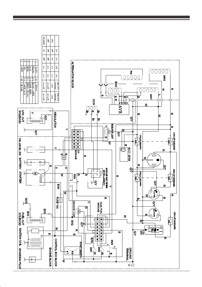
Wiring Diagram
Engli sh Cu stome r Servi ce: 1-8 44-FI RMAN1
39
Page 41
Service – Warranty
SERVICE I NFORMATION CONT ACT FIRMAN PRODUC T SERVICE DEPAR TM ENT AT 1-844-34 7-6261
or at www.f irmanpowerequ ipment.com to obt ain warranty se rv ice informati on or to order
replace ment parts or acces sories.
HOW TO ORDER REPLACEMENT PARTS
Even qual ity-built equip ment such as this ele ctric generat or m ay need occasio nal
replace ment parts to maint ain it in good condit ion over the year s. T o order replace ment parts,
please gi ve the following in formation:
Model No. Rev. Level and Serial No. found on the Data Decal.
Parts number or numbers as shown in the Parts List section.
A brief description of the trouble with the generator.
FIRMAN Three (3) Year Limited Warranty
Warranty Qualifications
Regis ter your pr oduct using the QR code provided or at www.firmanpowerequ ipment.com.
FIRMA N will also register the warranty upon receipt of your Warrant y Registration Card and a
copy of your sales rec eipt from on e of FIRMAN’s retai l locations as proo f of purchas e. Please
submi t your warr anty regi stration and your pr oof of purc hase within ten(10) days of the date of
purch ase.
Repair/Replacement Warranty
FIRMAN warrants to the original purchaser that the mechanical and electrical components will be free of
defects in material and workmanship for a period of one(1) year(parts and labor) and three(3) years (parts
and technical support) from the original date of purchase 90 days [parts and labor] and 180 days [parts]
for commercial & industrial use. Transportation charges on product submitted for repair or replacement
under this warranty are the sole responsibility of the purchaser . This warranty only applies to the original
purchaser and is not transferable.
Do Not Return the Unit to the Place of Purchase
Contact the FIRMAN Service Center and FIRMAN w il l tr ou bl es ho ot a ny i ss ue v ia p hone or e-mail.
If the problem is not corrected by t hi s me th od , FI RM AN w il l, a t its option, authorize evaluation,
repair or replacement of the defective part or c om po ne nt a t a FIRMAN Service Center. FIRMAN
will provide you with a case n um be r fo r wa rr an ty s er vi ce . Pl ea se k eep it for future reference.
Repairs or replacements without prior authorization, or at a n un au th or iz ed r ep ai r fa ci li ty , wi ll
not be covered by this warranty.
Warranty Exclusions
This warr anty does not cover t he following repa irs and equipme nt .
Normal Wear
Your prod uct needs periodi c parts and service t o perform well. T hi s warranty does n ot cover
repair wh en normal use has exh austed the life of a pa rt or the equipme nt a s a whole.
Engli sh Cu stome r Servi ce: 1-8 44-FI RMAN1
40
Page 42

Service – Warranty
Installation, Use and Maintenance
This warranty will not apply to parts and/or labor if your product is deemed to have been misused,
neglected, involved in an accident, abused, loaded beyond the generator's limits, modified,
installed improperly or connected incorrectly to any electrical component. Normal maintenance is
not covered by this warranty.
Other Exclusions
This warranty excludes:
– cosmetic defects such as paint, decals, etc.
– wear items
– accessory parts
– failures due to acts of God and other force majeure events beyond the manufacturer’s control
– problems caused by parts that are not original FIRMAN parts
– units used for prime power in place of existing utility power where utility is present or in place
of utility power where utility power service does not normally exist.
Limits of Implied Warranty and Consequential Damage
FIRMAN disclaims any obligation to cover any loss of time, use of this product, freight, or any
incidental or consequential claim by anyone from using this product. THIS WARRANTY IS IN
LIEU OF ALL OTHER WARRANTIES, EXPRESS OR IMPLIED, INCLUDING WARRANTIES OF MERCHANT
ABLILITY OR FITNESS FOR A PARTICULAR PURPOSE.
A unit prov ided as an exchange w ill be subject to the w arranty of the or iginal unit. The le ngth of
the warra nty governing the e xchanged unit wil l remain calcul at ed by reference t o the purchase
date of the o riginal unit.
This warr anty gives you cert ain legal rights wh ich may change fr om s tate to state. Yo ur state may
also have o ther rights you may b e entitled to that ar e not listed with in this warranty.
Contact Information
You may contact FIRMAN at:
Address
Firman Power Equipment Inc.
Attn: Customer Service
8644 W. Ludlow Dr.
Peoria, AZ 85381
www.firmanpowerequipment.com
We are FIRM AN POWER - And we are her e for you.
Engli sh Cu stome r Servi ce: 1-8 44-FI RMAN1
41
Page 43

Service – Warranty
FIRMAN POWER EQUIPMENT INC.
Emission Control System Warranty
CALIFORNIA AND FEDERAL EXHAUST AND EVAPORATIVE EMISSIONS CONTROL WARRANTY STATEMENT
YOUR WARRANTY RIGHTS AND OBLIGATIONS
The Californ ia Air Re sou rce s Board, US Environment al Protection Agency (“US EPA”) and FIR MAN POWER EQUI PME NT
INC.(FIRMAN) ar e pleased to explain the emissions cont rol systems warranty on your 2022- 202 3 or later Small Off-Road
Engine ( “SO RE” ) and eng ine powered equipment. I n Californi a, new eq uip men t that us e small off-road engines mus t be
designed, built and equi ppe d to meet the State’s stringent anti-smog standards. FIRMAN must warra nt the emi ssi ons cont rol
systems on your SORE and engine powered equipment for the periods of time liste d b elo w p rov ide d t her e h as bee n n o a bus e,
neglect or imp rop er maintenance of y our small off-road engine or equipment lea din g to the fail ure o f the emiss ion s control system.
Your emi ssion s cont rol sy stem m ay i nclud e part s such as the car bu retor or f uel-i nject ion sy stem, the ig nitio n syst em, ca talyt ic
conve rter, fu el tank s, fuel l ines (f or liqu id fuel a nd fuel v apors ), f uel cap s, valv es, can ister s, filt ers, cl amps an d other a ssoci ated
compo nents . Also inc luded m ay be hos es, bel ts, con necto rs, and o th er emis sion- relat ed asse mblie s.
Wh er e a w ar ra nt able co nd ition e xi st s, FI RM AN w ill r ep ai r you r SO RE an d en gine po we red equ ip me nt at n o cost to y ou
in cl ud ing d ia gn osis, p ar ts and la bo r.
MANUFACTURER'S WARRANTY COVERAGE:
The e xhaus t and eva porat ive emi ssion s contr ol syst em on you r small off-road en gine an d engin e power ed equi pment is warrante d
for t wo year s. If any e missi ons-r elate d part on your small of f-roa d engin e and eng ine pow ered eq uipme nt is def ectiv e, the pa rt will
be re paire d or repl aced by F IRMAN .
OWNER'S WARRANTY RESPONSIBILITIES:
As th e SORE an d engin e power ed equi pment o wner, y ou are re spons ible for the perfor mance o f the req uired m ainte nance
lis ted in yo ur oper ator' s manua l. FIRM AN reco mmend s that you retain all r eceip ts cove ring ma inten ance on y our SOR E and
eng ine pow ered eq uipme nt, but F IRMAN c annot d eny war ranty c overage solely fo r the lac k of rece ipts or f or your f ailur e to
ens ure the p erfor mance o f all sch edule d maint enance.
As th e SORE an d engin e power ed equi pment o wner, y ou shou ld howe ver be aw are that FIRMAN may d eny you w arran ty
cov erage i f your sm all off -road e ngine o r engin e power ed equi pment or a part has fai led due t o abuse , negle ct, or im prope r
mai ntena nce or un appro ved mod ifica tions .
You a re resp onsib le for pr esent ing you r small off-road en gine an d engin e power ed equi pment t o a FIRMA N distr ibuti on cent er
or se rvice c enter a s soon as t he prob lem exi sts. Th e warranty repair s shall b e compl eted in a r eason able am ount of t ime,
not t o excee d 30 days .
If yo u have an y quest ions re gardi ng your w arran ty righ ts and responsibilitie s, you sh ould co ntact F IRMAN a t 1-844 -347- 6261
or su pport @firm anpow erequ ipmen t.com .
FIRMAN Emission Control Defects Warranty Provisions
The warranty period begins on the date the engine/equipment is delivered to an ultimate purchaser. FIRMAN warrants to the ultimate
purchaser and each subsequent purchaser that the engine is:
Des igned , built , and equ ipped s o as to con form wi th all ap plica ble regulations a dopte d by the Ai r Resou rces Bo ard and U S EPA;
and F ree fro m defec ts in mat erial s and wor kmans hip tha t cause t he failure of a warra nted pa rt to be id entic al in all m ateri al
res pects t o the par t as desc ribed i n the eng ine man ufacturers appl icati on for ce rtifi catio n.
The w arran ty on emi ssion s-rel ated parts is as f ollow s:
(1) A ny warr anted p art tha t is not sc hedul ed for replacemen t as requ ired ma inten ance in t he owne r's manual suppli ed, is
war rante d for the w arran ty peri od stated above. If any such p art fai ls duri ng the pe riod of w arranty co verag e, the pa rt will b e
rep aired o r repla ced by FI RMAN at n o charg e to the ow ner. Any such part re paire d or repl aced un der the warranty wi ll be
war rante d for the r emain ing war ranty p eriod.
(2) A ny warr anted p art tha t is sche duled o nly for regular ins pecti on in the o wner' s manua l suppl ied, is warranted f or the wa rrant y
per iod sta ted abo ve. Any s uch par t repai red or re placed under warr anty wi ll be war rante d for the remaining w arran ty peri od.
(3) A ny warr anted p art tha t is sche duled f or replacement as r equir ed main tenan ce in the o wner' s manual supplied , is warr anted
for t he peri od of tim e prior t o the fir st sche duled r eplac ement point for tha t part. I f the par t fails p rior to t he firs t scheduled
rep lacem ent, th e part wi ll be rep aired o r repla ced by FI RMAN at no charge to th e owner . Any suc h part re paired or replace d
und er warr anty wi ll be war rante d for the remainder of the per iod pri or to the f irst sc hedul ed replacement po int for t he part .
(4) R epair o r repla cemen t of any wa rrant ed part under the war ranty m ust be pe rform ed at no ch arge to t he owne r at a warr anty
sta tion.
(5) N otwit hstan ding th e provi sions o f Subse ction ( 4) above, warrant y servi ces or re pairs m ust be pr ovide d by FIRM AN that
are f ranch ised to s ervic e the sub ject en gines.
(6) T he owne r must no t be char ged for d iagno stic la bor tha t leads to the determ inati on that a w arran ted part is in fact defectiv e,
pro vided t hat suc h diagn ostic w ork is pe rform ed at a war ranty station.
(7) F IRMAN i s liabl e for dam ages to o ther en gine co mpone nts pro ximat ely cau sed by a failure unde r warra nty of an y
war rante d part.
Engli sh Cu stome r Servi ce: 1-8 44-FI RMAN1
42
Page 44

Service – Warranty
(8) T hroug hout th e emiss ions wa rrant y perio d defined in Subsec tion (b )(2), F IRMAN w ill mai ntain a s upply o f warra nted
par ts suff icien t to meet t he expe cted de mand fo r such pa rts.
(9) A ny repl aceme nt part m ay be use d in the pe rform ance of a ny warrant y maint enanc e or repa irs and m ust be pr ovide d witho ut
cha rge to th e owner . Such us e will no t reduc e the war ranty obligatio ns of the m anufa cture r.
(10 ) Add-o n or modi fied pa rts tha t are not e xempt ed by the Air Resourc es Boar d may not b e used. T he use of a ny non- exemp ted
add -on or mo difie d parts b y the ult imate p urcha ser wil l be grounds for disa llowi ng a warr anty cl aim.
The manufact urer will not be liable to warrant fai lures of warra nted parts cau sed by the use of a non -exempted add-o n or modified
part.
PARTS COVERED BY WARRANTY
Lis ted bel ow are th e parts ( if equi pped) c overe d by the Federal and Ca lifor nia Emi ssion C ontro l Syste m Warra nty.
1. Ig nitio n syste m inclu ding:
- Spa rk plug
- Ign ition c oil
2. Fu el mete ring sy stem:
- Fue l tank
- Fue l cap
- Fue l lines (for l iquid f uel and f uel vapors) and
rel ated fi tting s/cla mps
- Fue l regul ator, c arbur etor an d inter nal par ts.
3. Ca talyt ic muff ler ass embly i nclud ing:
- Exh aust ma nifol d
- Cat alyti c conve rter
- Muf fler ga sket
-pu lse val ve
Limitations
Thi s Emiss ion Con trol Sy stem Wa rrant y shall n ot cove r any of th e follo wing:
(a) C onseq uenti al dama ges suc h as loss o f time, i nconv enien ce, los s of use of t he engi ne or equ ipmen t, etc.
(b) D iagno sis and i nspec tion fe es that d o not res ult in el igibl e warra nty ser vice being perfor med.
FIRMAN PO WER EQUIPMENT INC.
www.firmanpowerequipment.com
4. Ai r induc tion sy stem in cludi ng:
- Int ake pip e/man ifold
- Air c leane r
5. Cr ankca se brea ther as sembl y inclu ding:
- Bre ather c onnec tion tu be
6. Fu el tank e vapor ative e missi on cont rol sys tem inc ludin g:
- Pur ge valv es
- Car bon can ister
- Vap or hose s and fit ting/ clamp s
Engli sh Cu stome r Servi ce: 1-8 44-FI RMAN1
43
Page 45

TM
FIR MAN POWER EQ UIPME NT INC.
864 4 W. LUDLOW DR.
PEO RIA, AZ 8 5381
1-8 44-34 7-626 1
WWW. FIRMA NPOWEREQ UIPME NT.COM
All r ights r eserv ed. Any r eprin ting or u nauth orize d use
wit hout th e writt en perm issio n is expr essly p rohib ited.
P/N:380747010 Rev:01
 Loading...