

Page 1
1
U
Usseerr''ss
M
Maa
n
n
u
uaall
Version 1.7
Copyright © 2012. All rights reserved.
All other brand names are registered trademarks of their respective owners.
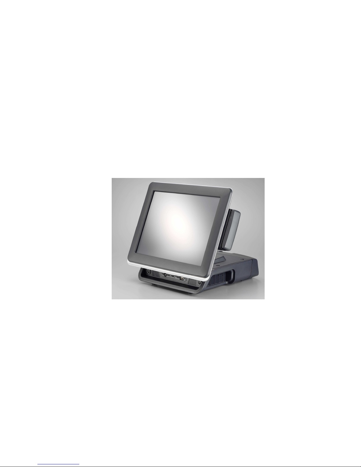
MegaPOS Lite
(M/B: FH-5251/FH-4551)
Mega POS MP-3000 Series
MP-3435 / MP-3432
MP-3425 / MP-3422
Page 2

Copyright Notice
This document is copyrighted, © 2012. All rights are reserved. Firich Enterprise Co., Ltd reserves
the right to make improvements of the product described in this manual at any time without notice.
No part of this manual may be reproduced, copied, translated, or transmitted in any form or by
any means without the prior written permission from Firich Enterprise Co., Ltd. Information
provided in this manual is intended to be accurate and reliable. However, Firich Enterprise Co.,
Ltd assumes no responsibility for its use, nor for any infringements upon the rights of third parties,
which may result from its use.
The material in this document is for product information only and is subject to change without
notice. While reasonable efforts have been made in the preparation of this document to assure its
accuracy, Firich Enterprise Co., Ltd, assumes no liabilities resulting from errors or omissions in
this document, or from the use of the information contained herein.
Page 3

Safety and Warranty
1. Read these safety instructions carefully.
2. Keep this user's manual for later reference.
3. Disconnect this equipment from any AC outlet before cleaning. Do not use liquid or spray
detergents for cleaning. Use a damp cloth.
4. For pluggable equipment, the power outlet must be installed near the equipment and must be
easily accessible.
5. Keep this equipment away from humidity.
6. Put this equipment on a reliable surface during installation. Dropping it or letting it fall could
cause damage.
7. The openings on the enclosure are for air convection. Protect the equipment from overheating.
DO NOT COVER THE OPENINGS.
8. Make sure the voltage of the power source is correct before connecting the equipment to the
power outlet.
9. Position the power cord so that people cannot step on it. Do not place anything over the power
cord.
10. All cautions and warnings on the equipment should be noted.
11. If the equipment is not used for a long time, disconnect it from the power source to avoid
damage by transient over-voltage.
12. Never pour any liquid into an opening. This could cause fire or electrical shock.
13. Never open the equipment. For safety reasons, only qualified service personnel should open
the equipment.
14. If any of the following situations arises, get the equipment checked by service personnel:
a. The power cord or plug is damaged.
b. Liquid has penetrated into the equipment.
c. The equipment has been exposed to moisture.
d. The equipment does not work well, or you cannot get it to work according to the user’s manual.
e. The equipment has been dropped and damaged.
f. The equipment has obvious signs of breakage.
15. DO NOT LEAVE THIS EQUIPMENT IN AN UNCONTROLLED ENVIRONMENT WHERE
THE STORAGE TEMPERATURE IS BELOW -20° C (-4°F) OR A BOVE 60° C (140° F). IT MAY
DAMAGE THE EQUIPMENT.
Page 4

TTaabbllee ooff CCoonntteennt
t
About this Manual................................................................................................................5
CChhaapptteerr 11
1
1
Introduction 1
MegaPOS Lite (MP-3435 / MP-3432) Introduction...............................................................1
A Quick Tour for MP-3435...................................................................................................2
MP-3435 Dimension............................................................................................................3
Rear I/O Panel.....................................................................................................................4
Packing List.........................................................................................................................5
Optional Devices:.................................................................................................................6
CChhaapptteerr 22
7
7
Hardware Installation and Upgrading 7
2.5” Hard Disk Drive Installation...........................................................................................7
Pole-Type VFD Installation..................................................................................................8
Memory (DDRII RAM) / DOM Installation.............................................................................9
Compact Flash Card (CF) Installation..................................................................................9
MCR Configuration Modification ........................................................................................10
Cash Drawer Installation....................................................................................................10
CChhaapptteerr 33
112
2
Software Installation and Setup 12
Driver Download from FEC Website Model .......................................................................12
Chipset Driver Installation..................................................................................................13
VGA Driver Installation.......................................................................................................15
LAN Driver Installation.......................................................................................................16
Audio Driver Installation.....................................................................................................17
Step 4. Click Finish and restart the system........................................................................17
ELO Touch Installation.......................................................................................................18
ELO Control Panel.............................................................................................................22
EETI TouchKit Tools Installation........................................................................................24
TouchKit Control Panel......................................................................................................28
Wireless LAN Driver Installation.........................................................................................29
CChhaapptteerr 44
331
1
Specifications 31
MP-3435 Specifications.....................................................................................................31
I/O Pin Definition................................................................................................................32
Jumper Setting ..................................................................................................................36
Troubleshooting 43
Touch Panel Does Not Work..............................................................................................43
ELO Touch Panel Cannot Calibrate Correctly....................................................................43
Cannot Detect HDD...........................................................................................................43
PS/2 Keyboard Is Not Functioning Normally......................................................................44
LAN Is Not Functioning Properly........................................................................................44
Page 5

COM1, COM2, COM5 Are Not Functioning Properly .........................................................44
Cash Drawer Port Is Not Functioning Properly...................................................................44
USB Device Is Not Functioning Properly............................................................................44
About this Manual
This manual contains all the information you need to set up and use MP-3435/3432.
Chapter 1 Provides an introduction to MP-3435/3432 and this manual.
Chapter 2 Provides all necessary information for all hardware setup.
Chapter 3 Provides the necessary information for installing for chipset and its accessories.
Chapter 4 Lists all MP-3435/3432 specifications.
Chapter 5 Troubleshooting of MP-3435/3432.
Page 6
MP-3435 / MP-3432 System manual v
ersion 0.3
1
CChhaapptteerr 11
IInnttrroodduuccttiioonn
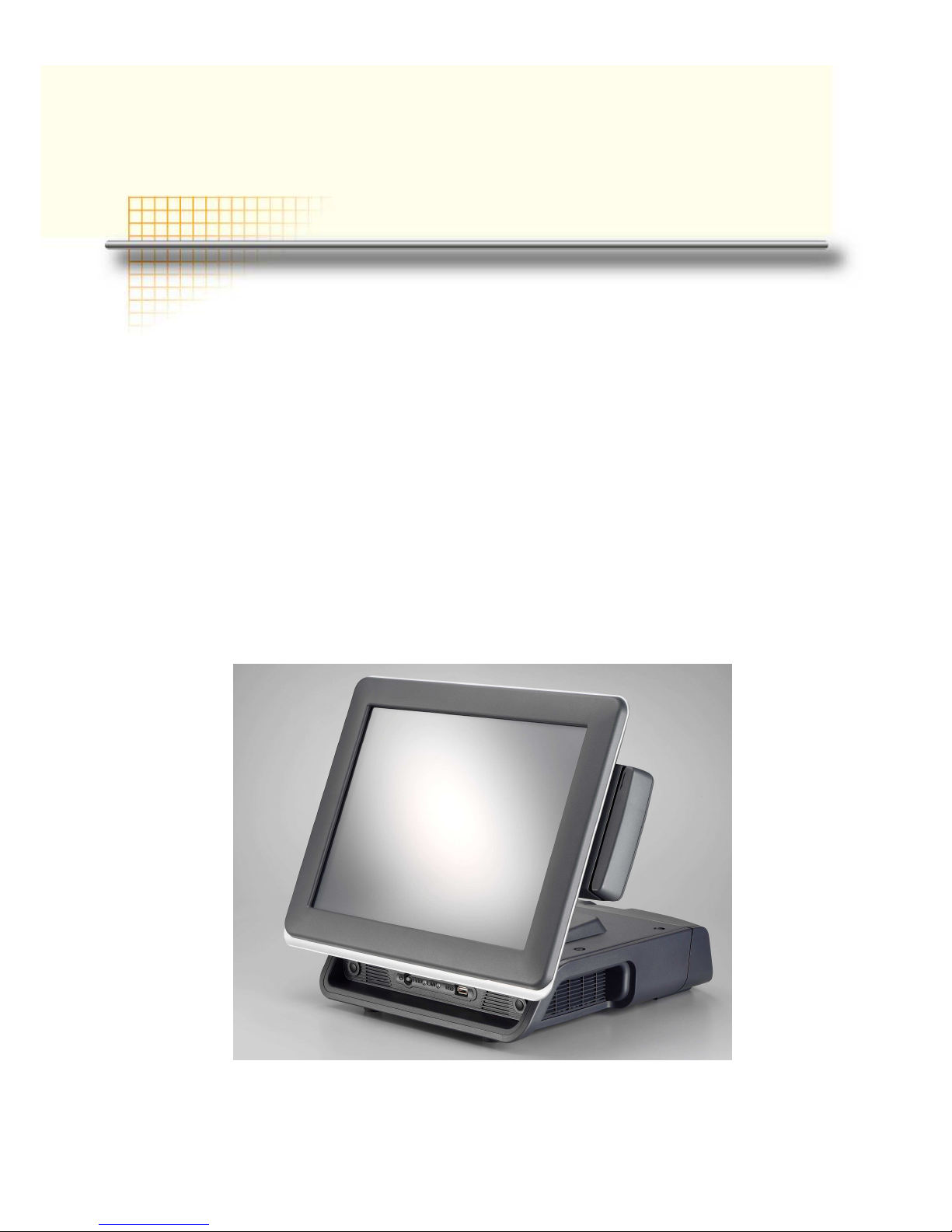
MegaPOS Lite (MP-3435 / MP-3432) Introduction
To reach the balance of budget-saving and strong requirement for product quality, MegaPOS Lite
is designed with quality-oriented and cost-effective concept. Fanless as it is, MP-3435 / MP- 3432
provide a decent choice for noise-free environment applications with optimized product reliability.
Main Features:
• The most cost-effective solution with built-in customer display and 12VDC out for 2nd
display connection without extra adaptor needed.
• Fanless solution for green and noise-free environment.
• Easy maintenance for system parts, such as HDD, CF, and RAM…etc.
• Sufficient I/O access for various connection requirements.
• Integrated cable cover for supporting pole-type VFD / LCD display.
• Compliant with IP54 front panel standard
MP-3435 w/ cable cover & MCR
Page 7

MP-3435 / MP-3432 System manual v
ersion 0.3
2
A Quick Tour for MP-3435
Before you start, take a moment to become familiar with MP-3435.
Identification Device
1st Display
External I/O
(inside the cable)
Built-in Customer
Display (LCM)
HDD LED / LAN LED / USB Port
HDD Location
(in the bottom)
Power Switch
with LED
Syste
m Venting
Cable Cover
2nd Display Stand for
Pole-Type VFD/LCD
(attached with 2nd
display option)
Antenna
Page 8
MP-3435 / MP-3432 System manual v
ersion 0.3
3
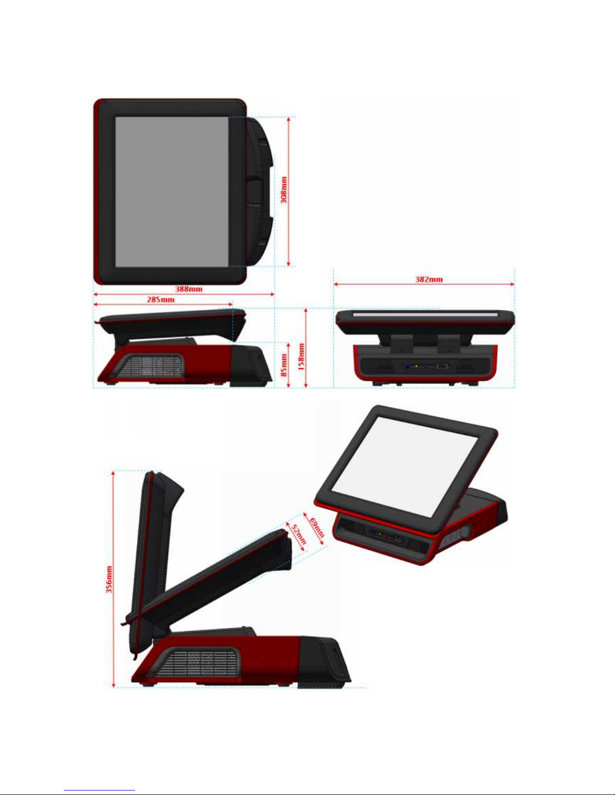
MP-3435 Dimension
Page 9
MP-3435 / MP-3432 System manual v
ersion 0.3
4
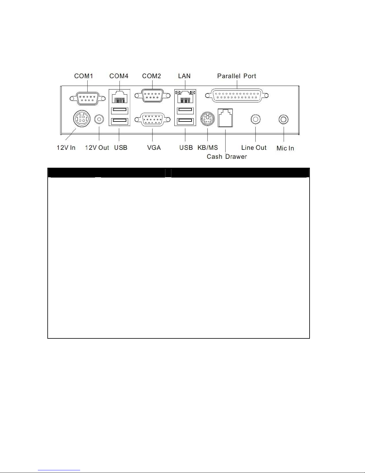
Rear I/O Panel
I/O Port Connector Type Description
Audio Jack
Earphone connector Connect the speakers to this port
USB
USB type A
connector
Standard USB connector for external device
DC IN
DC-in connector Connect the power adaptor to this port
+12V DC Out
12V DC-out
connector
This DC-out port can sustain the power of the
monitor or any other devices which need 12V
DC power input.
COM 4
VFD / RJ45
connector
COM4 This RJ45 port can be used to attach a
VFD customer display or serve as an additional
serial port (switching cable provided).
Cash Drawer
RJ11 connector Cash Drawer Connector, 12 V actuation support
KB / MS
PS2 connector Connect the keyboard or mouse to this port
COM 1
COM 2
D-SUB 9 connector
The serial ports COM1/COM2 can be used to
connect devices such as a printer or a
fax/modem.
LPT
Parallel 25-pin LPT
Connector
The standard LPT (D-SUB 25 pin) connector for
connecting POS printers or KeyPro solution
LAN
RJ45 connector Connect MP-3435 to the Ethernet
VGA
D-Sub 15 Pin
Connector
The VGA port is used for connecting LCD or
CRT monitors
Page 10
MP-3435 / MP-3432 System manual v
ersion 0.3
5
Packing List
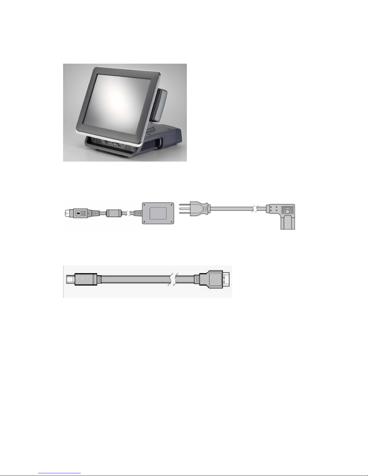
• MP-3435 / MP-3432 Main System x 1
• Power Adaptor x 1 / AC Power Cord x 1
• COM port switching cable (RJ45 to D-SUB 9 pin) x 1
Page 11
MP-3435 / MP-3432 System manual v
ersion 0.3
6
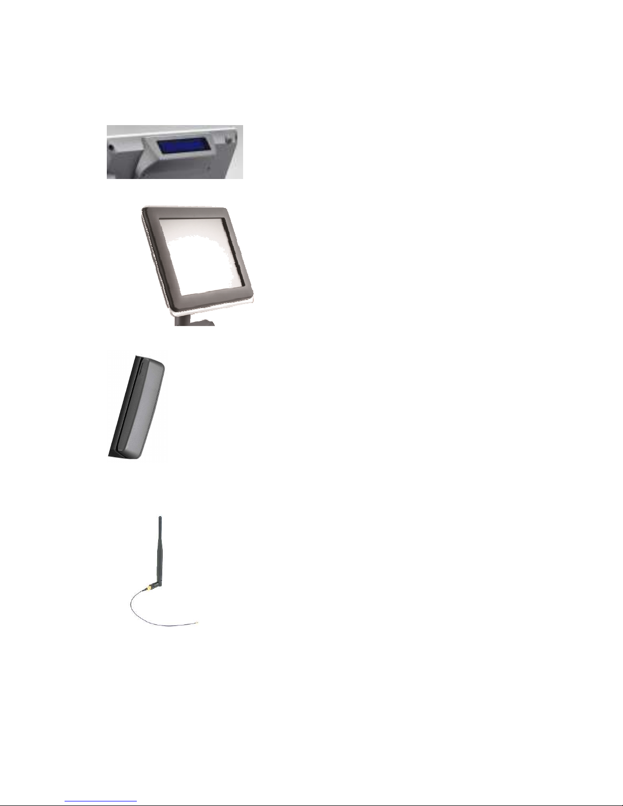
Optional Devices:
• Integrated LCM Display
• Pole-type Customer Display
• MCR
• WiFi Wireless Module
Page 12
MP-3435 / MP-3432 System manual v
ersion 0.3
7
CChhaapptteerr 22
HHaarrddwwaarree IInnssttaallllaattiioonn aanndd UUppggrraaddiinngg
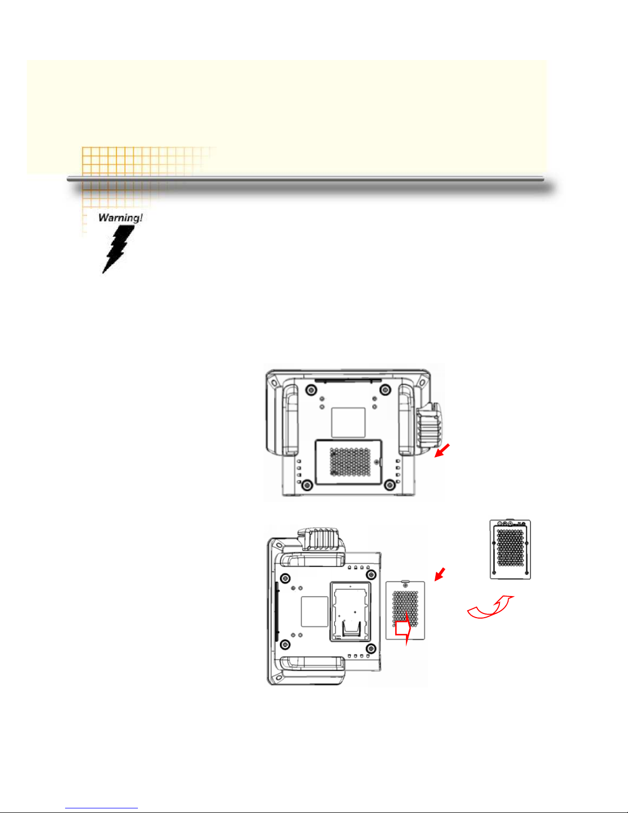
2.5” Hard Disk Drive Installation
1. Turn off power and remove power cord from the system
2. Unscrew the maintenance
door at the bottom of the
unit
3. Remove the door and flip it
over
Do not remove the rear cover until you have verified that no power is
supplied to the system. Power must be switched off and the power cord
must be unplugged. Every time you service the system, you should be
aware of this.
Page 13
MP-3435 / MP-3432 System manual v
ersion 0.3
8
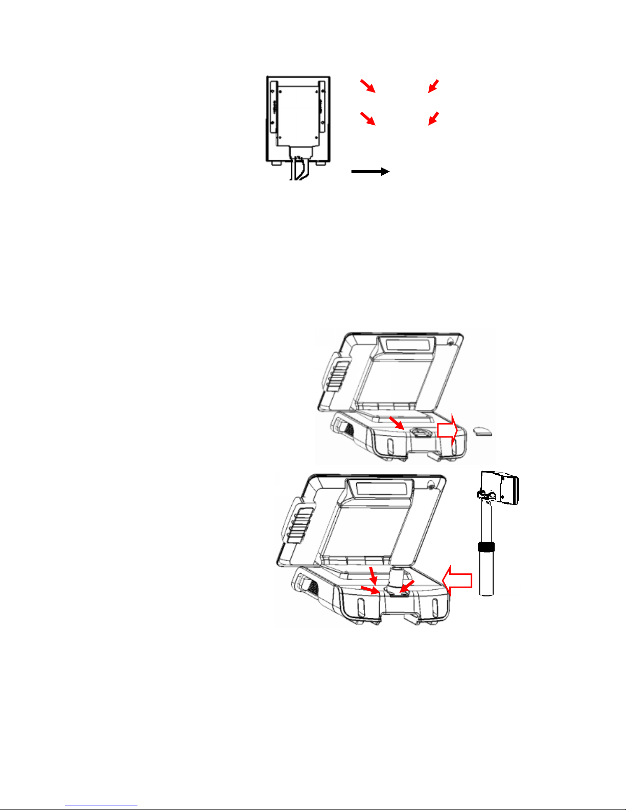
4. Place HDD kit on the door,
fasten it with 4 screws and
connect with the SATA
cable.
5. Restore the maintenance door to the system.
6. Fix the door with the screw.
7. Connect the power cord to the system.
Pole-Type VFD Installation
1. Remove the plastic cover on
the cable cover
2. Fix the pole stand with
screws and place the poletype customer display to the
stand
3. Connect the RJ45 or RS-232 (D-Sub 9) cable to the system.
SATA cable
2.5”
HDD
Page 14
MP-3435 / MP-3432 System manual v
ersion 0.3
9
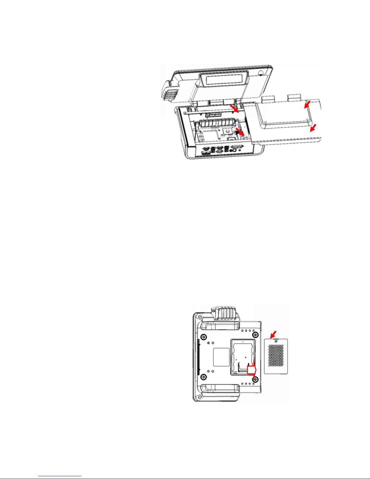
Memory (DDRII RAM) / DOM Installation
1. Unscrew and remove the
top cover
2. Install the DDRII RAM or DOM you require
3. Before restore the top cover, please check the thermal pad stays
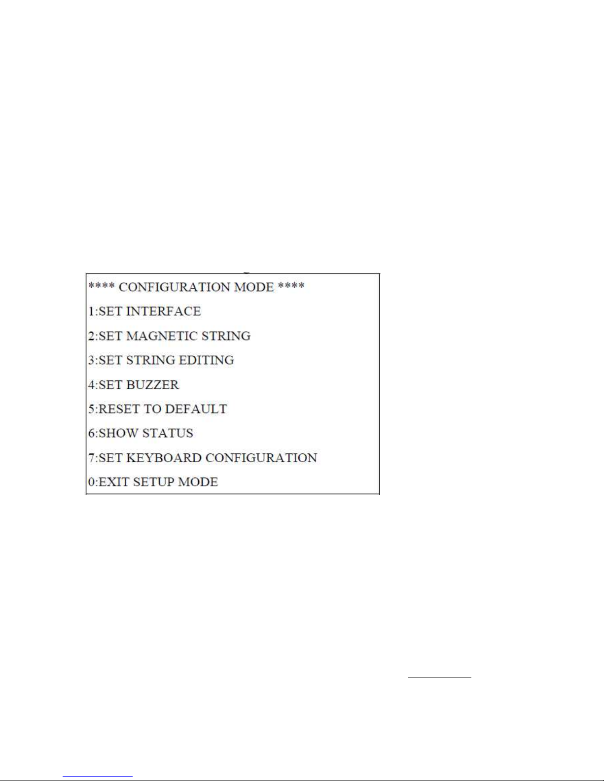
Compact Flash Card (CF) Installation
1. Unscrew and remove the
maintenance door
2. Install the CF you require
3. Restore the maintenance door
Page 15
MP-3435 / MP-3432 System manual v
ersion 0.3
10
MCR Configuration Modification
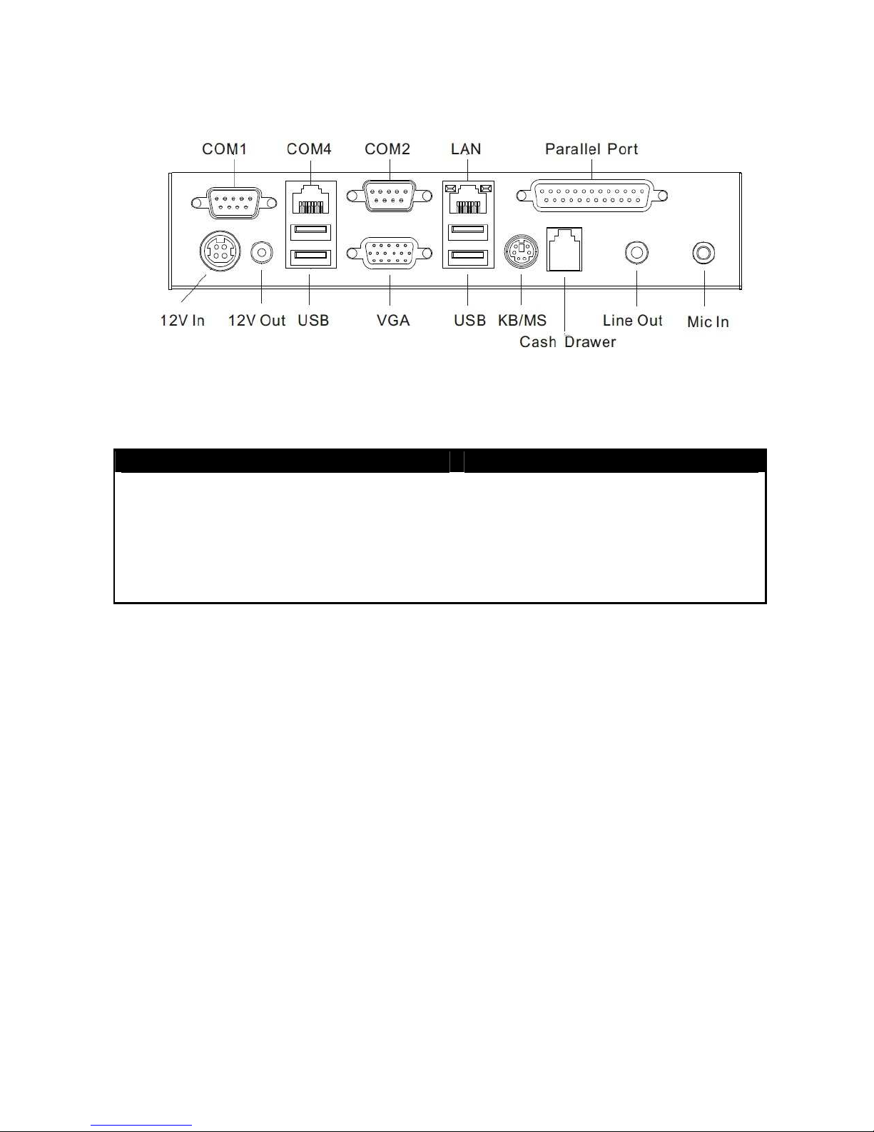
This option is for users who need to customize the MCR configurations for a particular task.
To enter the Configuration Mode, please execute text editor program (such as Microsoft Word,
Notepad…etc.) first, and then press [Ctrl] + [Alt] + [F10]. The following menu will appear
accordingly.
For detailed instruction, please refer to the MSR212 Programmer’s Manual under the path below
in the driver CD: Utility\Pos Utility\MCR util\Uniform
Cash Drawer Installation
Before connecting the cash drawer to the MP-3435 / MP-3432, please make sure the drive
voltage and cable pin assignment of the cash drawer matches the definition of the cash drawer
port of MP-3435 / MP-3432. Please refer to the jumper setting and pin definition(for more
information on the Cash Drawer.
Plug cash drawer cable into cash drawer port.
Note: If the cash drawer cannot be detected by the system, please refer to troubleshooting.
Page 16
MP-3435 / MP-3432 System manual v
ersion 0.3
11
Up to two cash drawers may be driven from this port. Driving voltage of the solenoid is
DC+12V. I/O port 284 is used for drawer operation. A test program is supplied, for Linux and
Windows, source code of which is available on request by software developers.
Value Description
0x284 Output address.
0x284 read 8bit Bit 2 => 0: low 1: high
0x200 Sleep 200ms
0x01 Open cashdrawer1 value.
0x02 Open cashdrawer2 value.
0x04 Close cash-drawer value.
0x04 Cash-drawer status mask.
Page 17
MP-3435 / MP-3432 System manual v
ersion 0.3
12
CChhaapptteerr 33
SSooffttwwaarree IInnssttaallllaattiioonn aanndd SSeettuupp
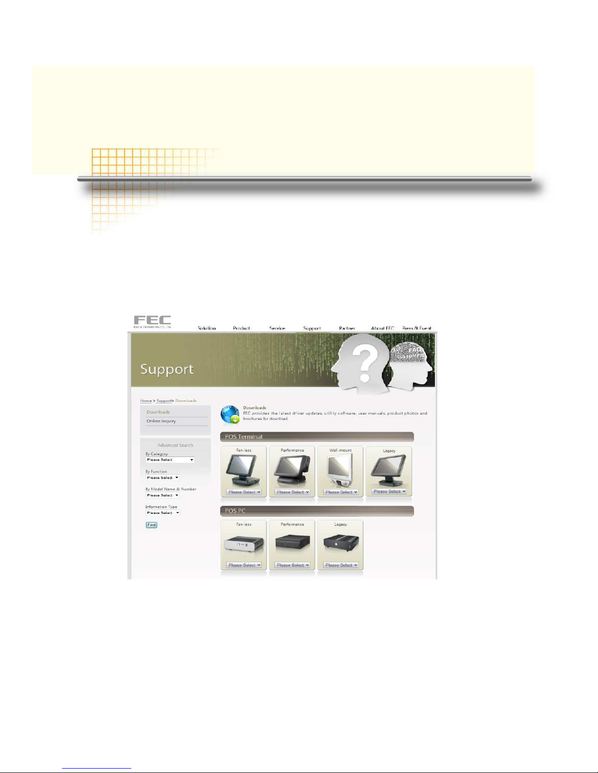
Driver Download from FEC Website Model
A: Please go to FEC website and download the drivers.
B: The installation sequence: Chipset Driver -> VGA Driver -> LAN Driver -> Audio Driver
- >Touch Driver ->Other Driver (optional)
C: Then, you can start to install.
Please follow this installation sequence accordingly.
Page 18
MP-3435 / MP-3432 System manual v
ersion 0.3
13
Chipset Driver Installation
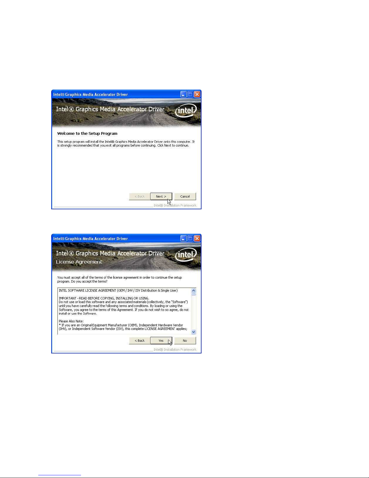
Intel ATOM D525 Chipset Installation Utilities for Windows XP
Step 1. Please download the Intel chipset driver from website.
Step 2. Click Next
Step 3. Read the License Agreement and click Yes.
Page 19
MP-3435 / MP-3432 System manual v
ersion 0.3
14
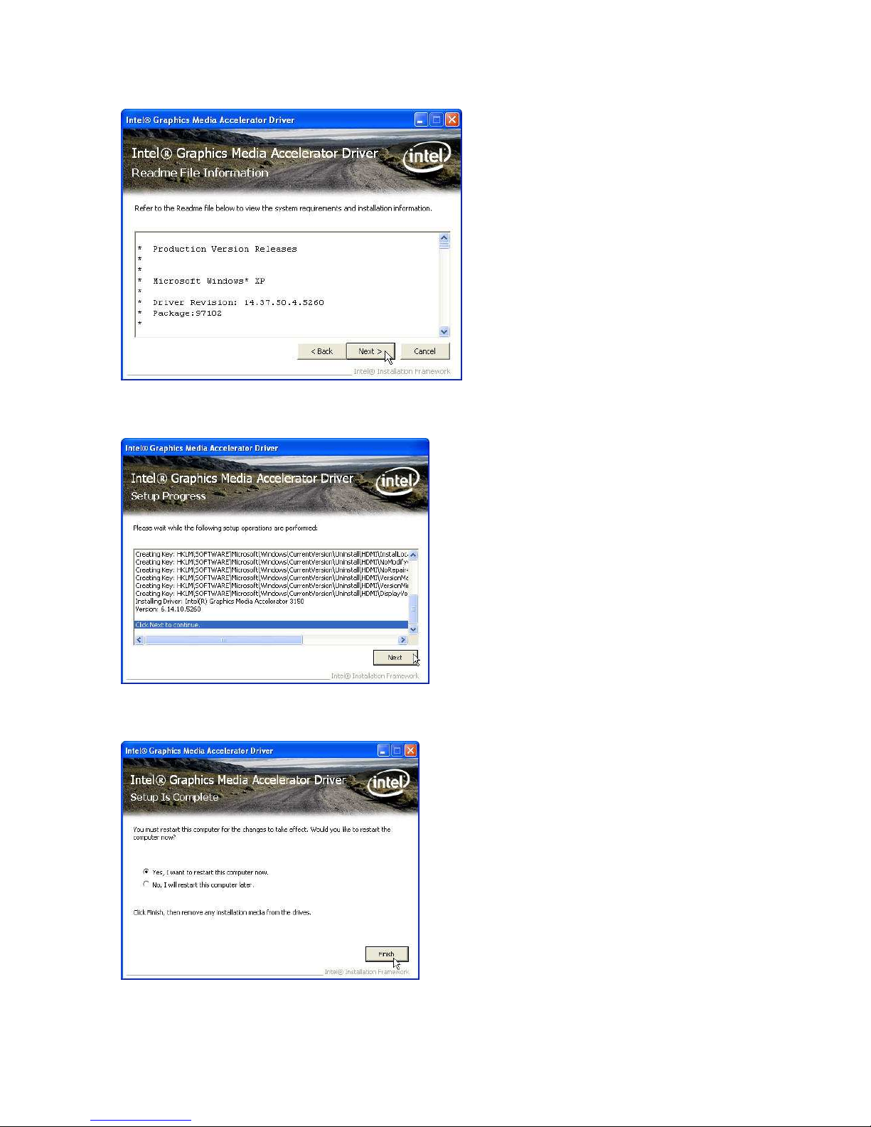
Step 4. Click Next and the drivers for the Intel Chip set will install.
Step 5. Please wait while the setup program processing.
Step 6. When the 'Setup COMPLETE' message appears click Finish to restart your computer.
Page 20
MP-3435 / MP-3432 System manual v
ersion 0.3
15
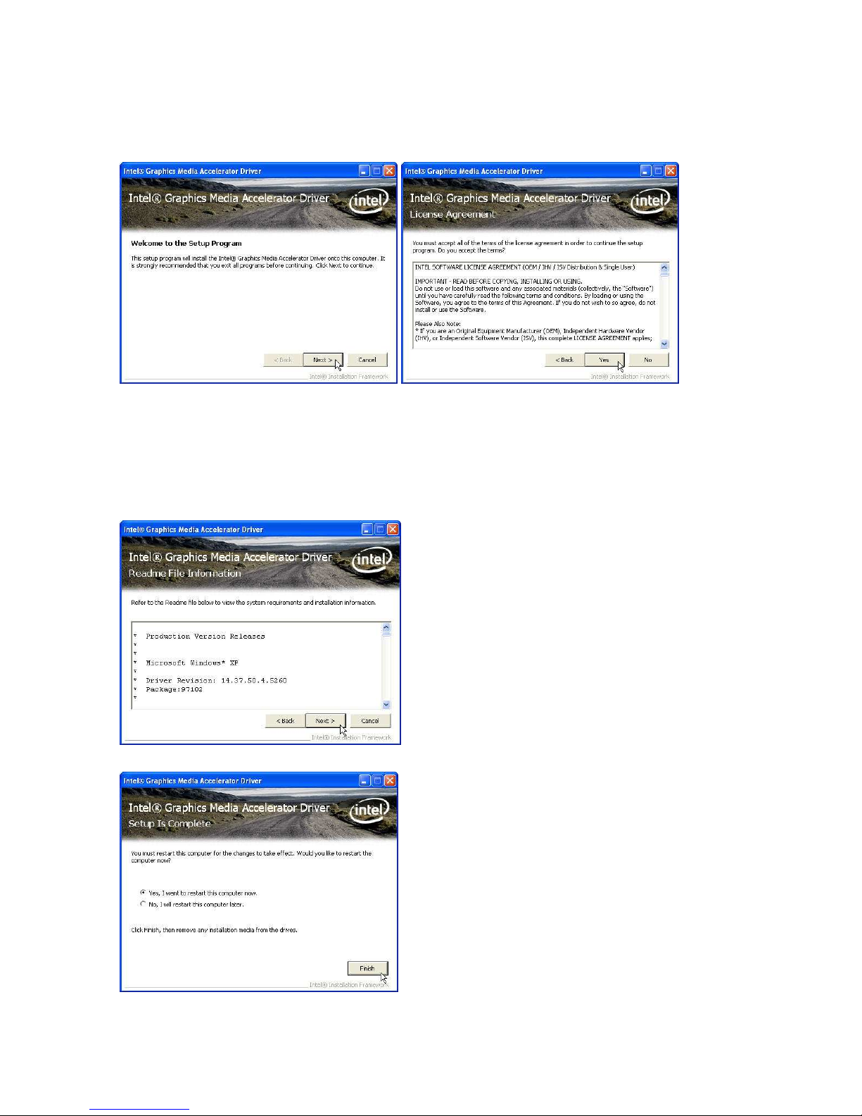
VGA Driver Installation
Step 1. Please download the VGA driver from website
Step 2. Click Next and click Yes of License Agreement Page
Note:
When installing the IEGD driver for VGA under POSready 2009, the default setting is
800x600 with Clone mode; if you need to use Extension Mode, please set the 2nd panel
as primary as below. (Warning: After you set the panel to Extension Mode, it won’t be
available to set back to Clone Mode due to the driver issue.)
Step 3. Select Next to continue driver installation.
Step 4. Finally, Finish and Restart the system
Page 21
MP-3435 / MP-3432 System manual v
ersion 0.3
16
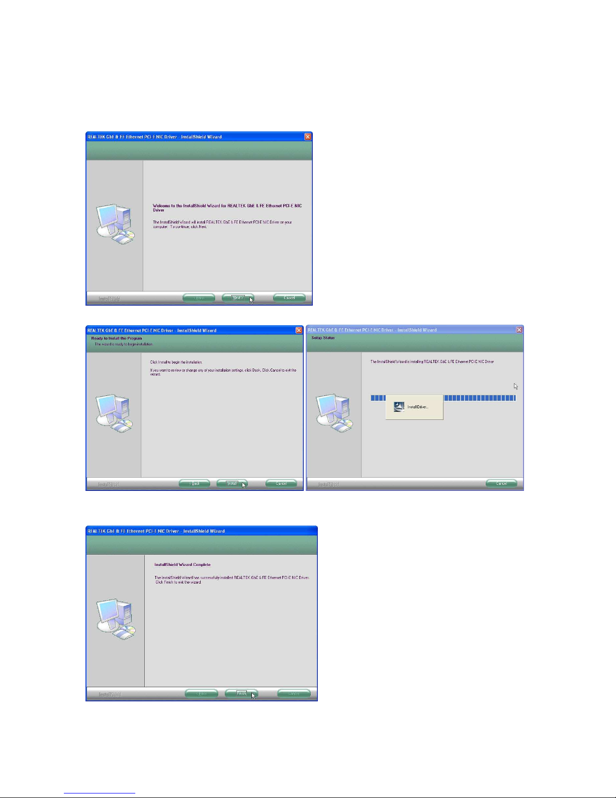
LAN Driver Installation
Step 1. Please double confirm the LAN driver from website.
Step 2. Click “Next” to continue
Step 3. Click “Next” to continue
Step 4. Click Next to continue
Step 5. Click Finish to complete the installation procedure.
Page 22
MP-3435 / MP-3432 System manual v
ersion 0.3
17
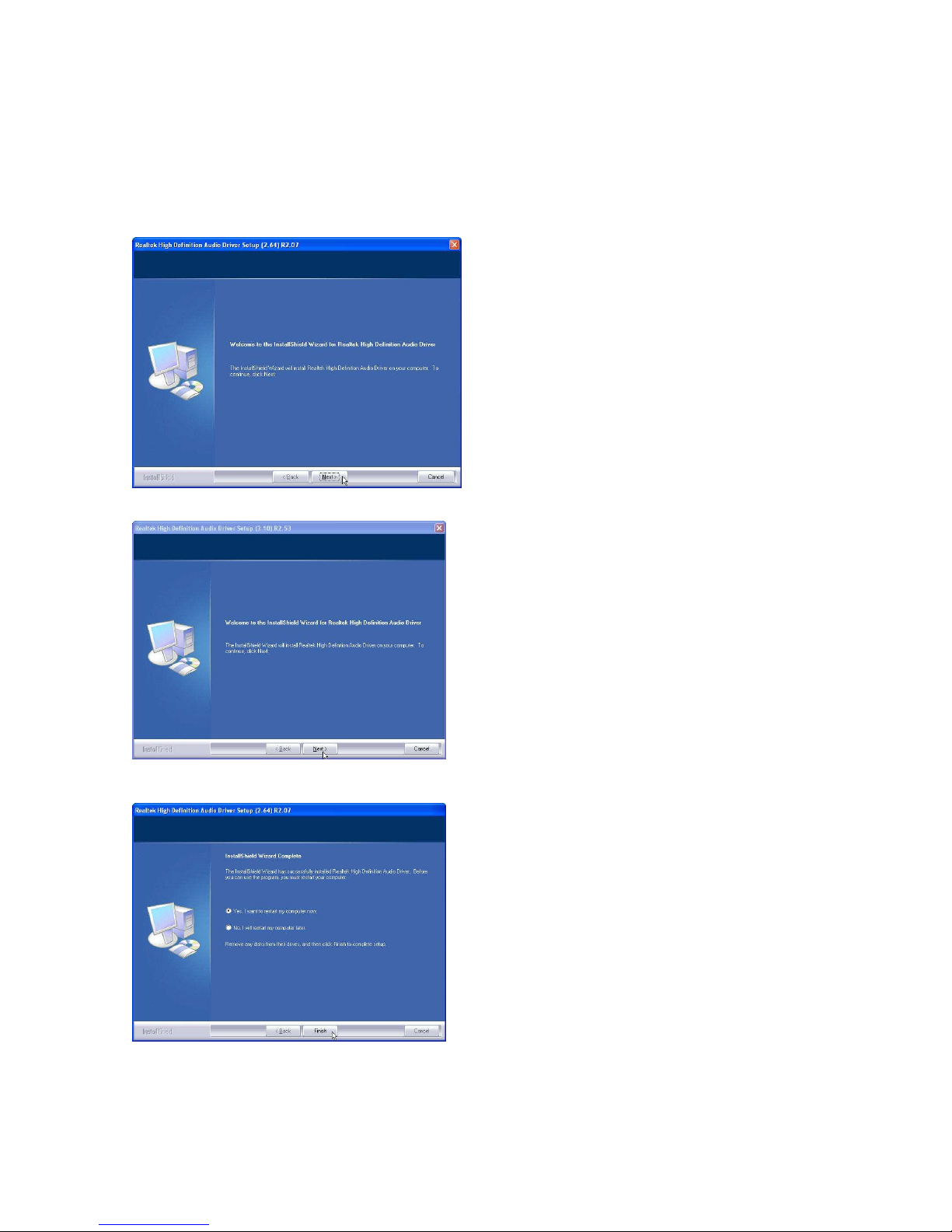
Audio Driver Installation
Step 1. Please download the Audio driver from website.
Step 2. Click “Next” to continue
Step 3. Click Next to continue.
Step 4. Click Finish and restart the system.
Page 23
MP-3435 / MP-3432 System manual v
ersion 0.3
18
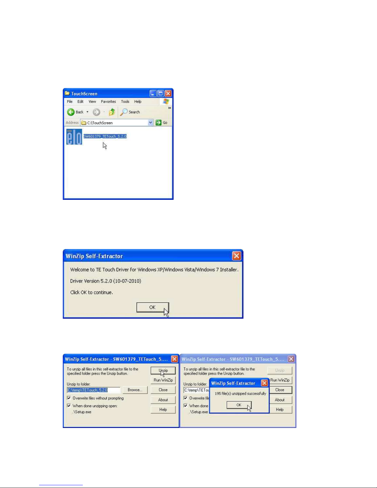
ELO Touch Installation
1.
Find the setup file through index(Tools)
2. Open SW601854_TETouch_5.4.2.exe (for latest version, please reference to FEC
website)
3. Click OK to continue.
4. Click Unzip; Unzip the files successfully and click OK to continue the installation.
Page 24
MP-3435 / MP-3432 System manual v
ersion 0.3
19
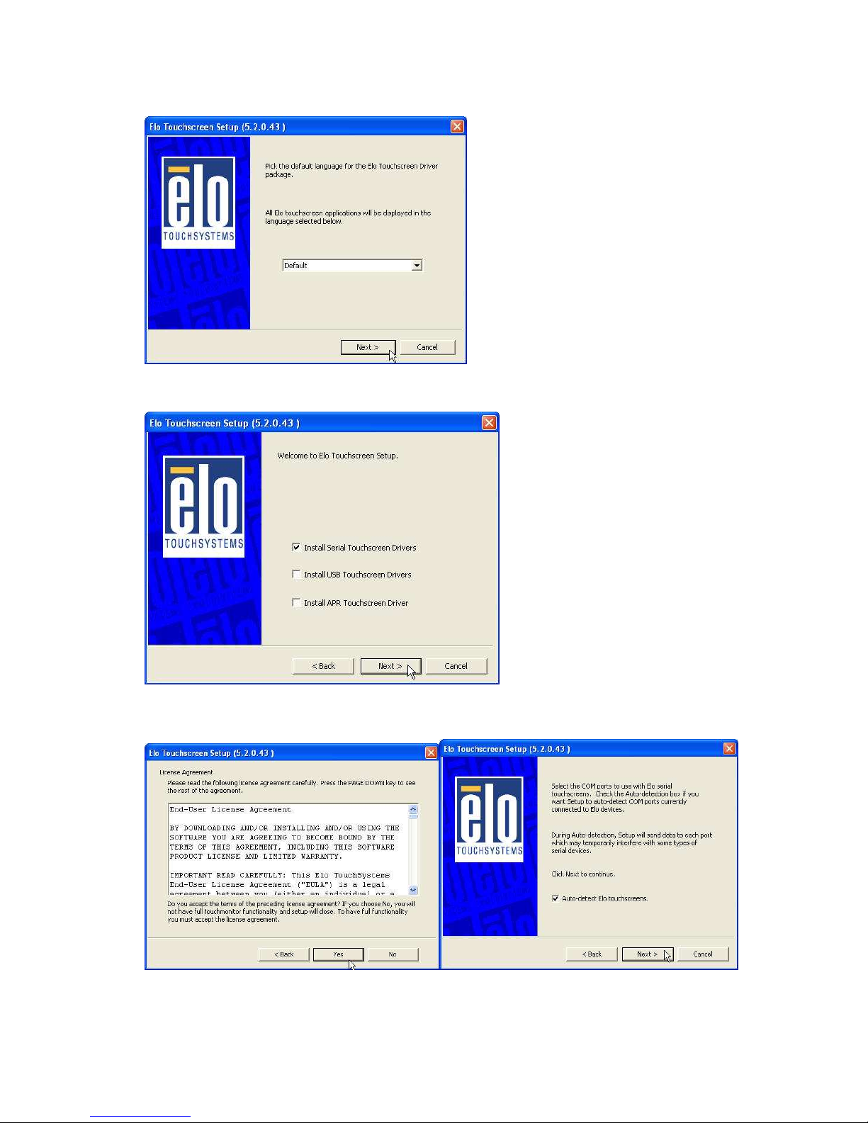
5. Click Next to continue.
6. Choose Install Serial Touch Screen Driver and click Next to continue.
7. Read the “License Agreement” and click Yes and select Auto Detect ELO
touchscreens and click Next
Page 25
MP-3435 / MP-3432 System manual v
ersion 0.3
20
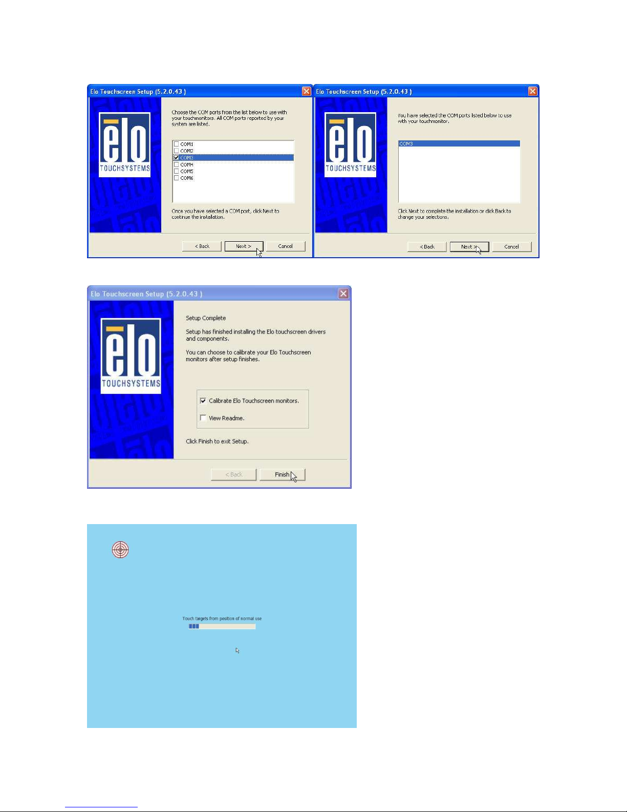
8. Select COM3 and click Next for further installation steps.
9. Setup complete and execute Calibrate Elo Touch Screen Monitors and Click Finish.
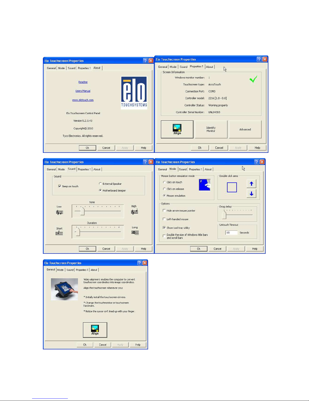
10. Start calibrating the touchscreen by touch the targets showed on the screen.
Page 26
MP-3435 / MP-3432 System manual v
ersion 0.3
21
11. According to ELO Touch Screen Properties; Make sure the COM port listed is COM3 for
your touch monitor; adjust a proper sound of touch buzzer Press Next to continue.
Page 27
MP-3435 / MP-3432 System manual v
ersion 0.3
22
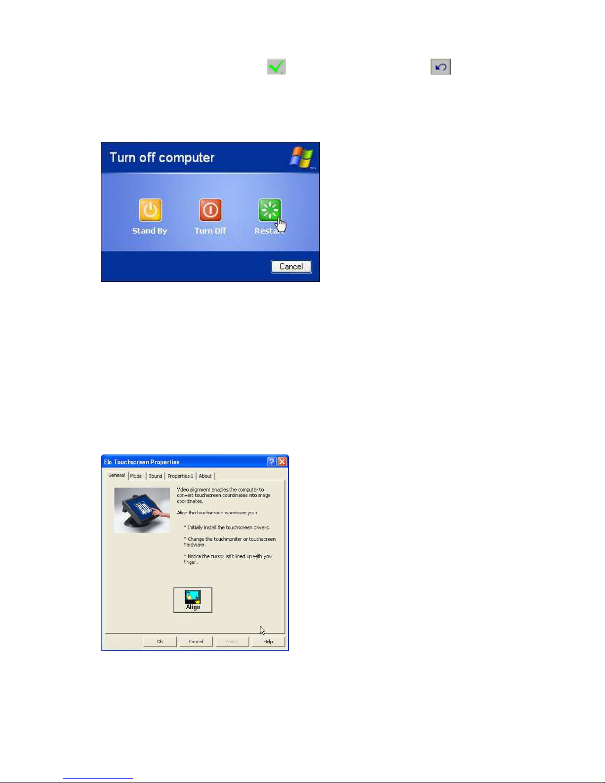
12. If the cursor is working fine, click to finish the setting; if not, click to calibrate the
screen again.
IT MAY BE NECESSARY TO RESTART YOUR COMPUTER TO UTILIZE YOUR
TOUCHSCREEN FEATURES.
13. Click Restart to reboot your computer again.
ELO Control Panel
This section explains the different options in the ELO control Panel.
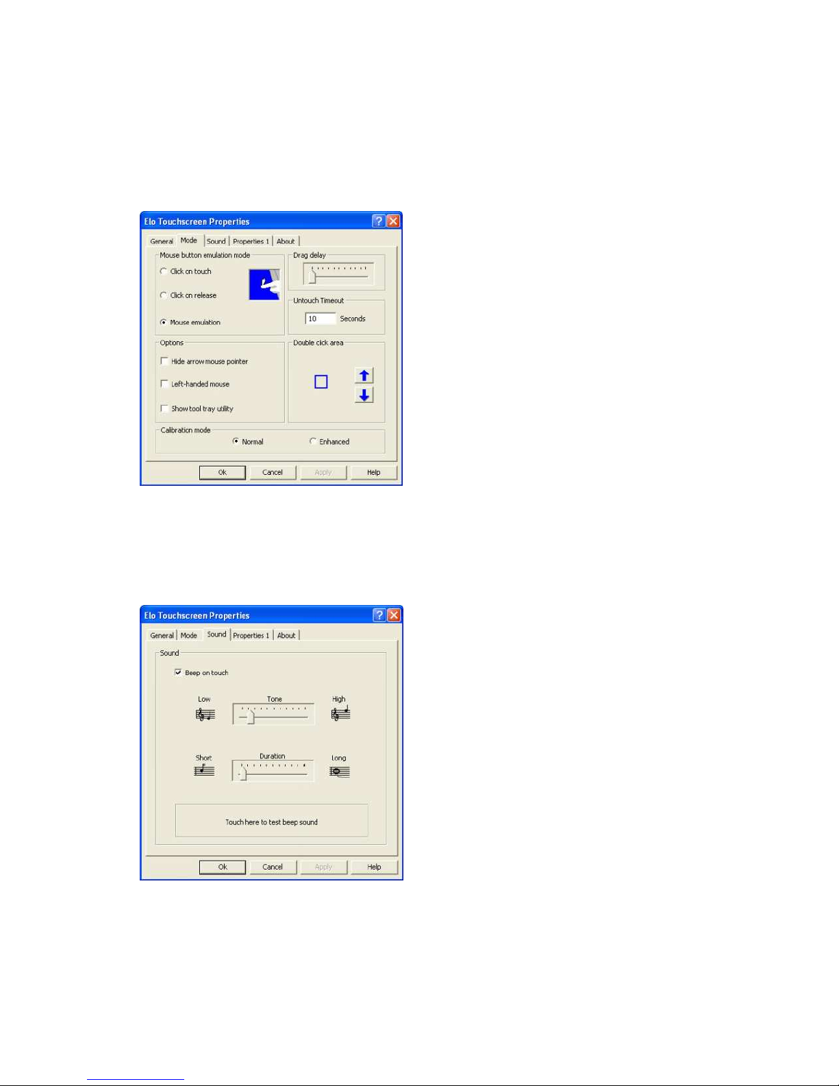
General tab
The general tab allows you to:
• Change the COM port your touch screen is set to.
• Calibrate the touch screen with the Align button.
Page 28
MP-3435 / MP-3432 System manual v
ersion 0.3
23
Mode tab
The Buttons tab allows you to:
• Adjust all mouse emulation controls.
• Change cursor properties
• Enable or disable right mouse button utility.
Sound tab
The Sound tab allows you to:
• To change sound properties for ELO touch tools.
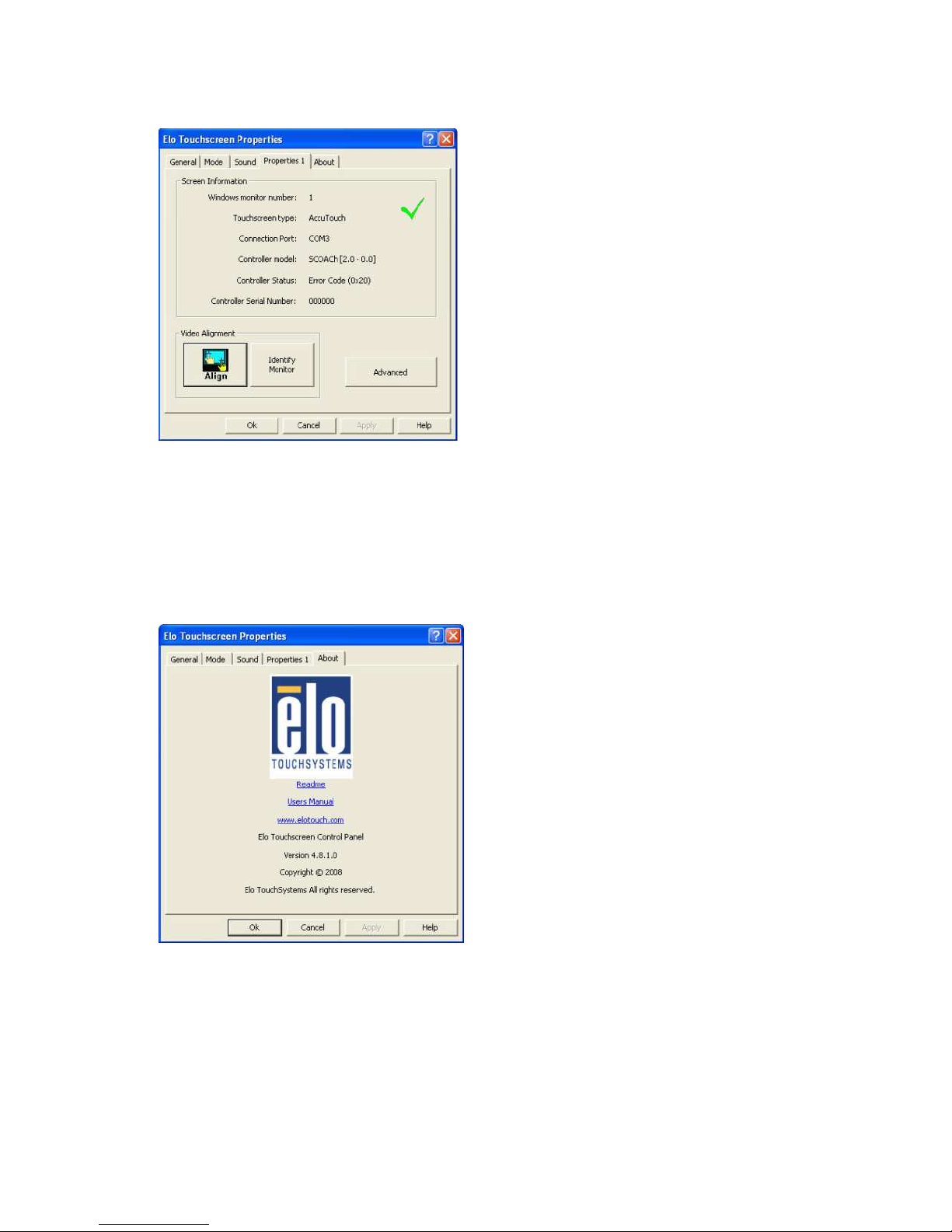
Properties tab
The Diagnostics tab allows you to:
Page 29
MP-3435 / MP-3432 System manual v
ersion 0.3
24
• View Controller Information.
About tab
The About tab displays Information about ELO Touch systems
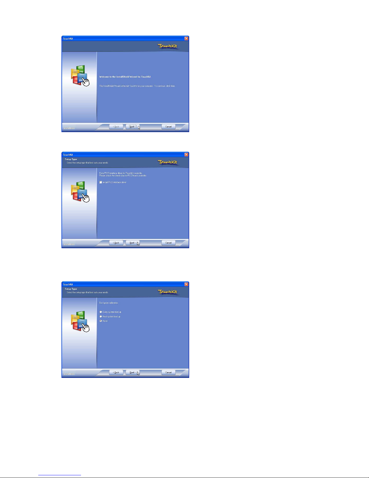
EETI TouchKit Tools Installation
Step 1. Please double confirm the EETI driver downloaded from website
Step 2. Click “OK” to continue unzip the driver
Step 3. Open Setup.exe
Page 30
MP-3435 / MP-3432 System manual v
ersion 0.3
25
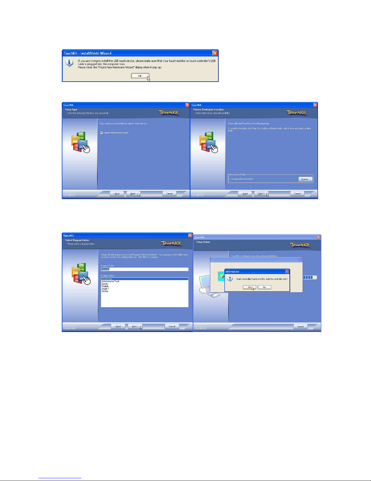
Step 4. Click Next
Step 5. Click Next
Page 31
MP-3435 / MP-3432 System manual v
ersion 0.3
26
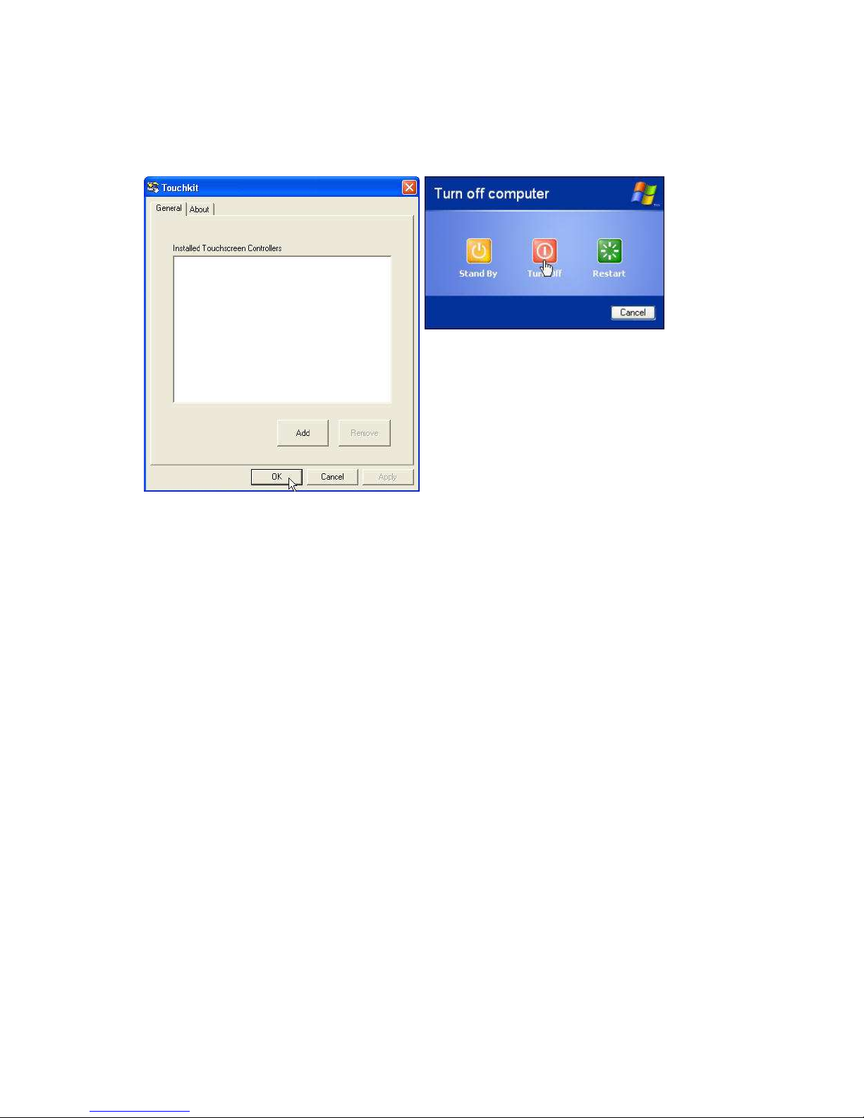
Step 6. Click OK to close the pop-up dialog.
Step 7. Click “Support Multi-Monitor System” and then Next to continue.
Step 8. Click Next
Page 32
MP-3435 / MP-3432 System manual v
ersion 0.3
27
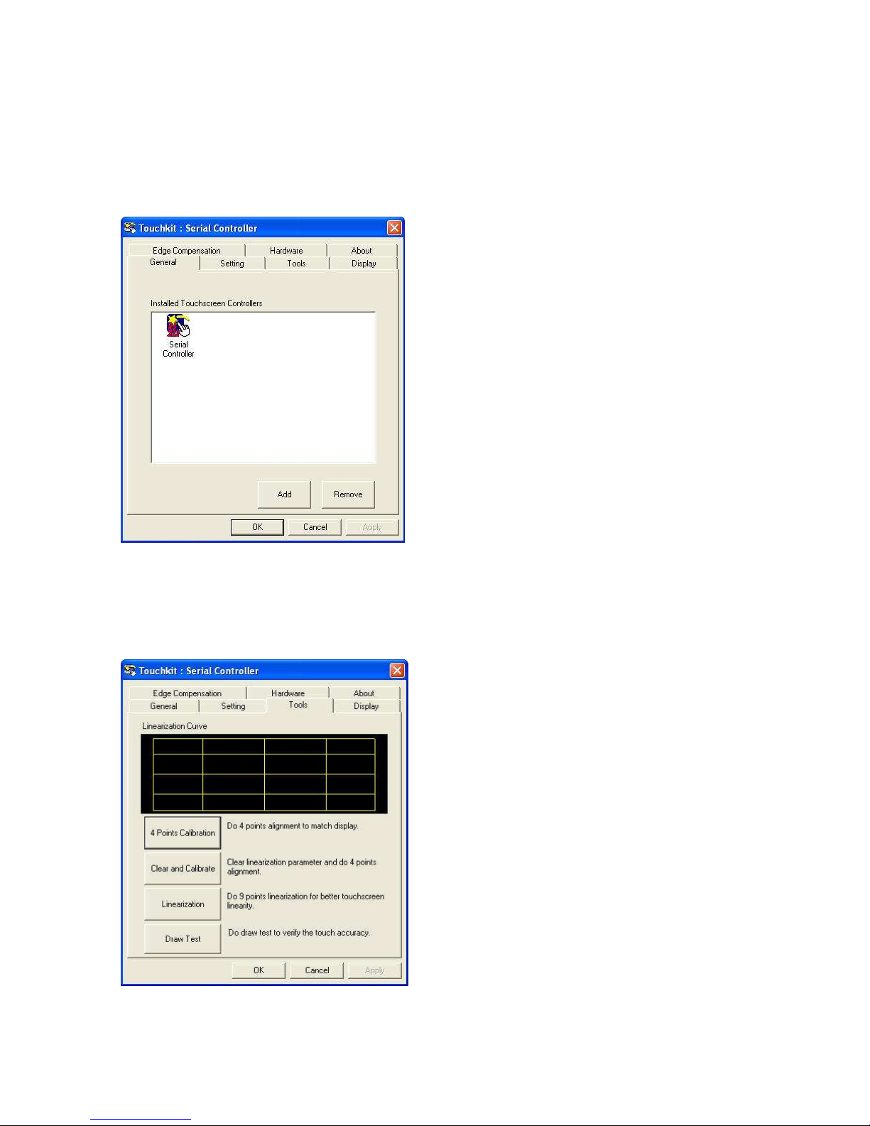
Step 9. Click OK and turn off the computer to restart your system again.
After the system finish rebooting follow the directions to calibrate the Touch screen.
Page 33
MP-3435 / MP-3432 System manual v
ersion 0.3
28
TouchKit Control Panel
This section explains the different options in the TouchKit control Panel.
General tab
The general tab allows you to:
• Manage the touch screen controller you installed.
Tools tab
The tools tab allows you to:
• Calibrate the touch screen with the 4 Points Calibration button.
Page 34
MP-3435 / MP-3432 System manual v
ersion 0.3
29
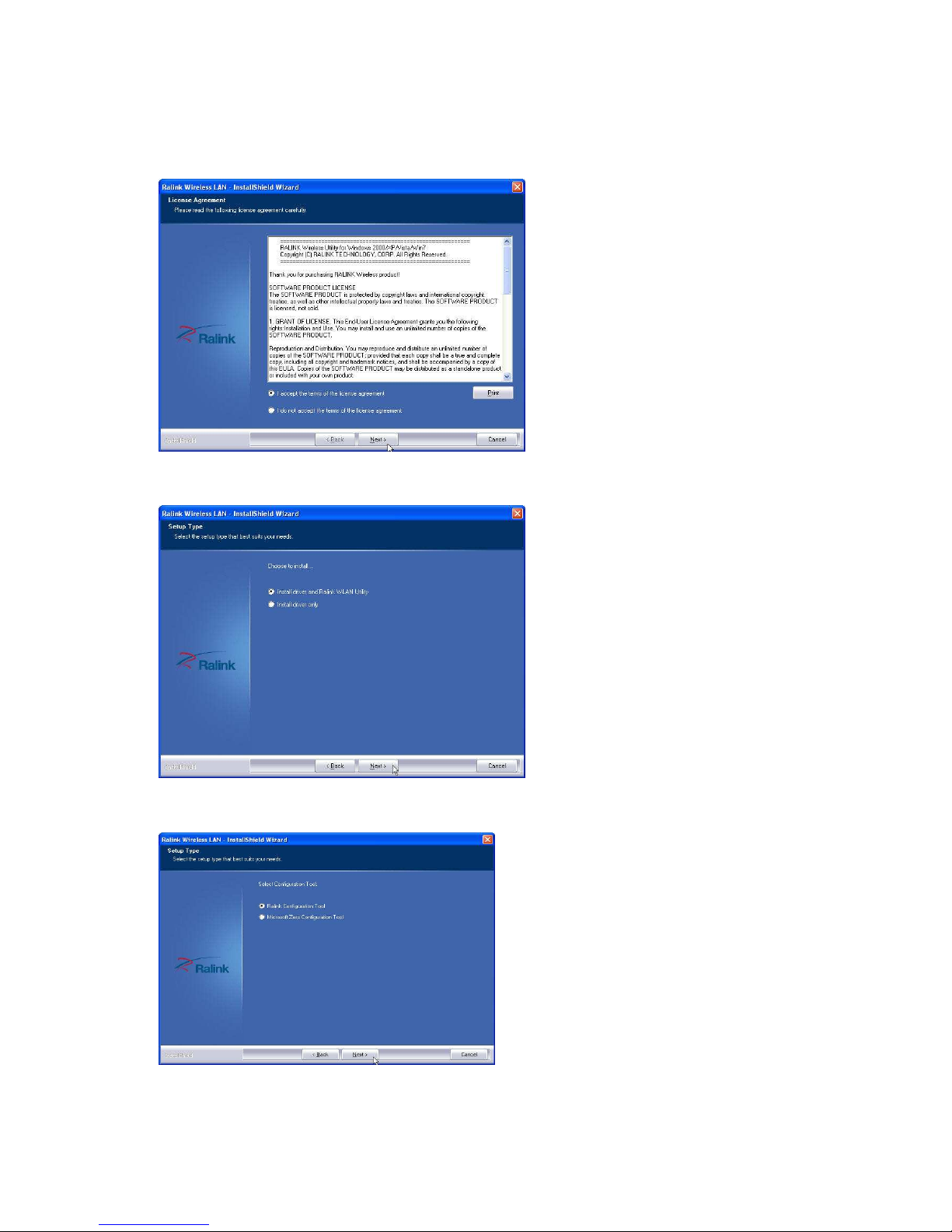
Wireless LAN Driver Installation
Step 1. Please double confirm the Wireless LAN driver from website.
Step 2. Click “Next” to continue
Step 3. Select Install driver and Ralink WLAN Utility
Step 4. Select “Ralink Configuration Tool”Select “Optimize for WiFi mode”
Page 35
MP-3435 / MP-3432 System manual v
ersion 0.3
30
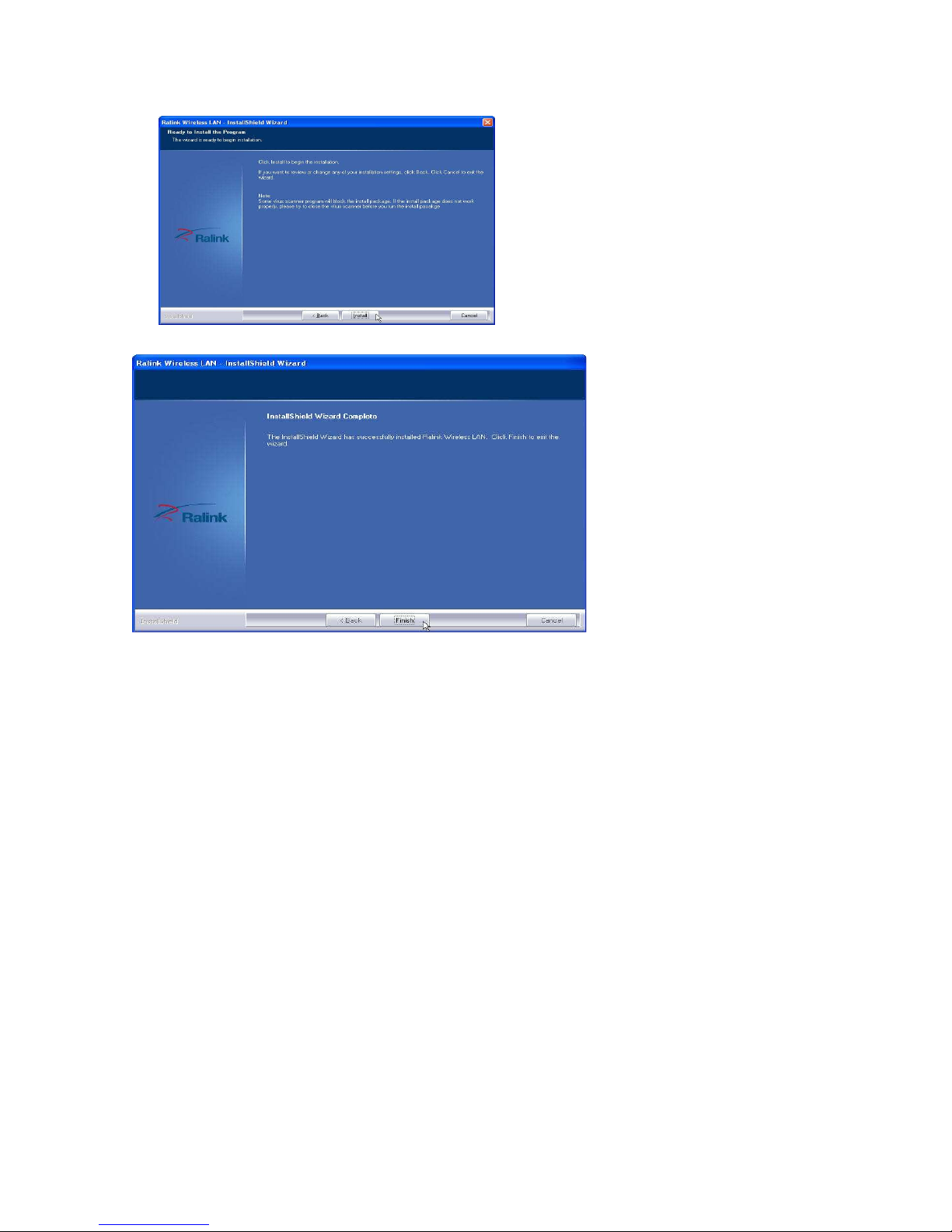
Step 5. Select Install to continue
Step 6. Select Finish to complete the installation
Page 36
MP-3435 / MP-3432 System manual v
ersion 0.3
31
CChhaapptteerr 44
SSppeecciiffiiccaattiioonnss
MP-3435 Specifications
System Configuration
CPU (On Board)
INTEL ATOM D525 (1.8GHz with 1M L2 cache)
Chipset
ICH8M
Memory
1 x 204pin DDR3 up to 4GB memory
VGA controller
GMA3150
LCD Panel
15” TFT LCD Panel (1024x768).
Touch Panel
15” with 5-wire Resistive Touch Panel
Storage
Internal 2.5” Serial ATA 160GB hard disk drive as default
Support type II Compact Flash™ Disk.
Speaker
Integrated 2W x 2 stereo system speakers
Power
90 watts external power adaptor
I/O Port
Serial Port
3 x User available COM ports (COM1, COM2, COM5).
2 x System assigned COM ports (COM3 & COM5).
COM3 for primary touch screen.
COM5 for built-in LCM customer display
1 x Reserved (COM6).
Parallel Port
Support EPP/SPP/ECP
USB Port
6 x USB 2.0 ports (1*Internal, 5*External)
Cash Drawer Port
RJ11 Cash drawer port,12V actuation.
Keyboard Port
One PS/2 keyboard port.
LAN Port
Giga Ethernet LAN, Realtek RTL8111E
VGA Port
Standard D-SUB 15 Pin VGA Port
Audio Port
Integrated Sound Blaster compatible (Realtek ALC269)/Built-in
stereo speakers
Optional Features
Customer display
Built-in LCM module
Pole-type VFD customer display
Pole-type LCD customer display
MSR
External Magnetic Stripe Card Reader track 1/2/3
Wireless
Internal WiFi Module(USB)
Power Consumption
Page 37
MP-3435 / MP-3432 System manual v
ersion 0.3
32
Power
Consumption
20 – 30W
(Standard system while running programs and accessing HDD).
Operating temperature
Operating
Temperature
0 ℃ ~ 40 ℃
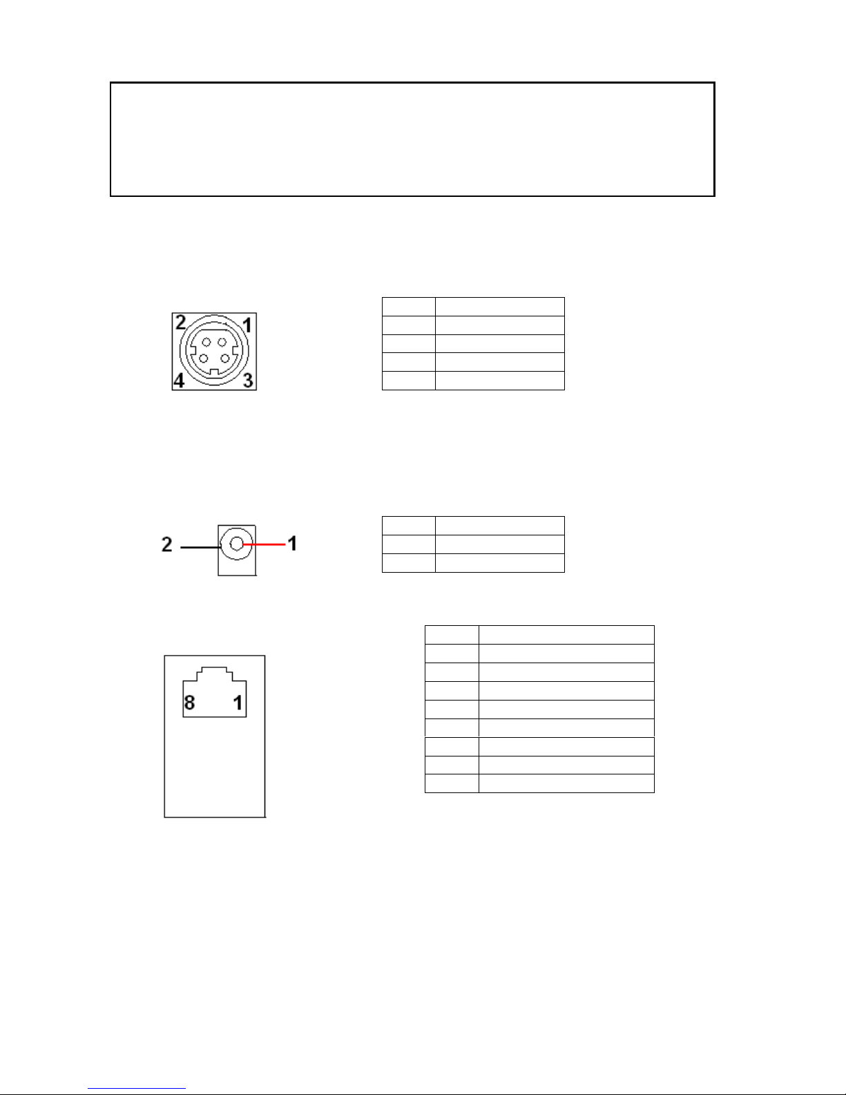
I/O Pin Definition
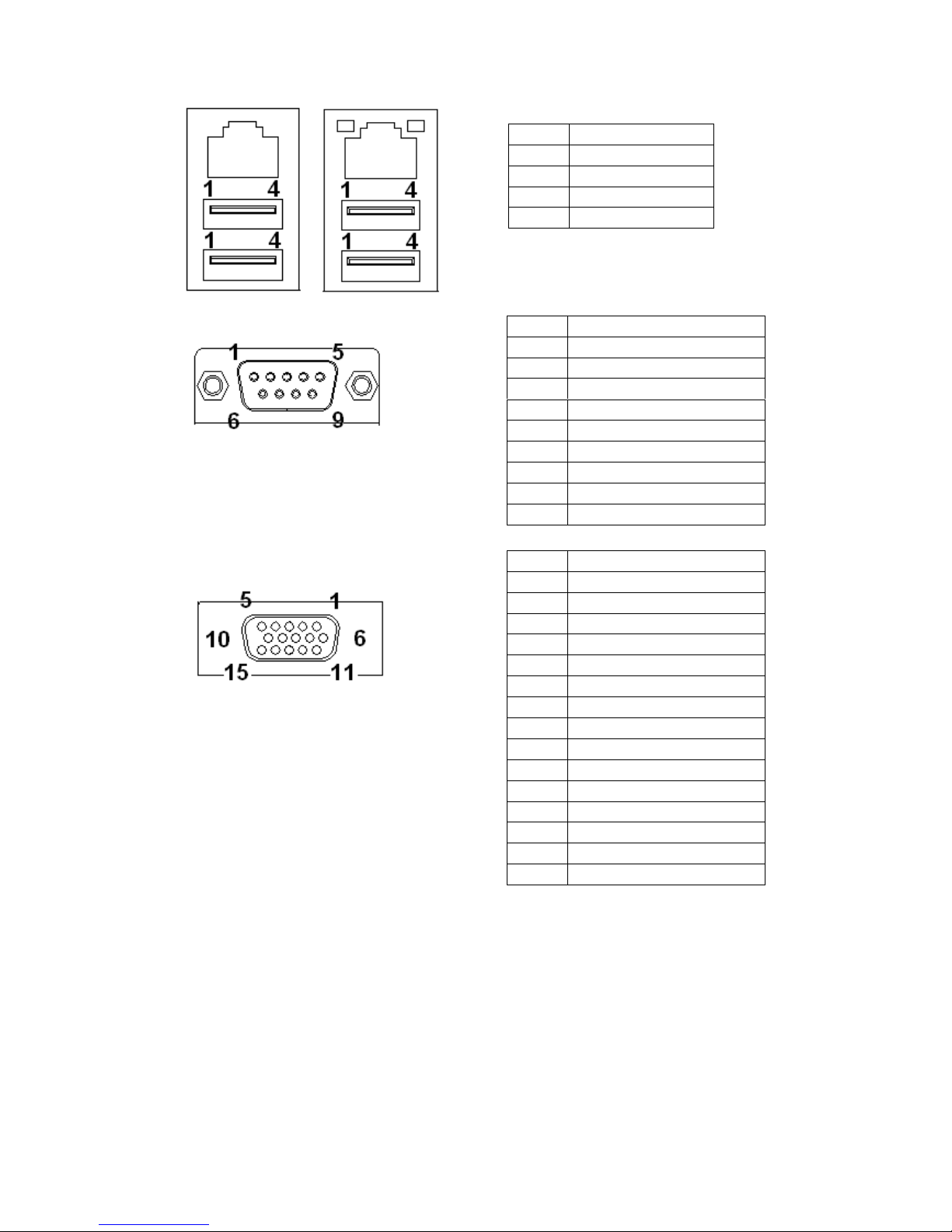
A. DC_IN (DC Adapter 12V in)
B. +12V_OUT (12V OUT)
C. COM4_USB1 (VFD & RS-232 port + USB 2.0/1.1 port)
The definition of pin1 , pin 2 and pin4 are depending on jumper setting from
JCOM4 and VFD_JR1
D. USB 2.0/1.1 Port
Pin Definition
1 12V
2 GND
3 12V
4 GND
DC_IN
+12V_OUT
Pin Definition
1 12V
2 GND
COM4_USB1
Pin Definition
1 RI/ 5V /12V
2 CTS or RI/5V/12
3 GND
4 RTS or GND
5 DTR
6 DSR
7 TXD
8 RXD
COM4_USB1 USB_LAN1
Page 38
MP-3435 / MP-3432 System manual v
ersion 0.3
33
E. COM2
F. VGA
G. USB_LAN1 (LAN connector RJ45+USB 2.0/1.1 Port)
Pin Definition
1 USB 5V
2 D3 D+
4 GND
COM2
Pin Definition
1 DCD
2 RXD
3 TXD
4 DTR
5 GND
6 DSR
7 RTS
8 CTS
9 RI/ 5V /12V
VGA
Pin Definition
1 RED
2 GREEN
3 BLUE
4 NC
5 GND
6 GND
7 GND
8 GND
9 VCC 5V
10 GND
11 NC
12 DDC Data
13 H-SYNC
14 V-SYNC
15 DDC Clock
Page 39
MP-3435 / MP-3432 System manual v
ersion 0.3
34
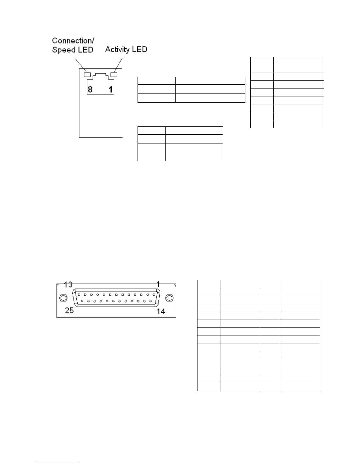
H. LPT Port
USB_LAN1
Connection/Speed LED:
State Description
Orange Speed:1 Gbps
Green Speed:1 00 Mbps
State Description
On
Transmitting
Off Not
Transmitting
Activity LED:
Pin Definition
1 Data 0+
2 Data 03 Data 1+
4 Data 15 Data 2+
6 Data 27 Data 3+
8 Data 3-
LPT
Pin Definition Pin Definition
1 STB- 14 AFD2 PD0 15 ERR3 PD1 16 INIT4 PD2 17 SLIN5 PD3 18 GND
6 PD4 19 GND
7 PD5 20 GND
8 PD6 21 GND
9 PD7 22 GND
10 ACK- 23 GND
11 BUSY 24 GND
12 PE 25 GND
13 SLCT
Page 40
MP-3435 / MP-3432 System manual v
ersion 0.3
35
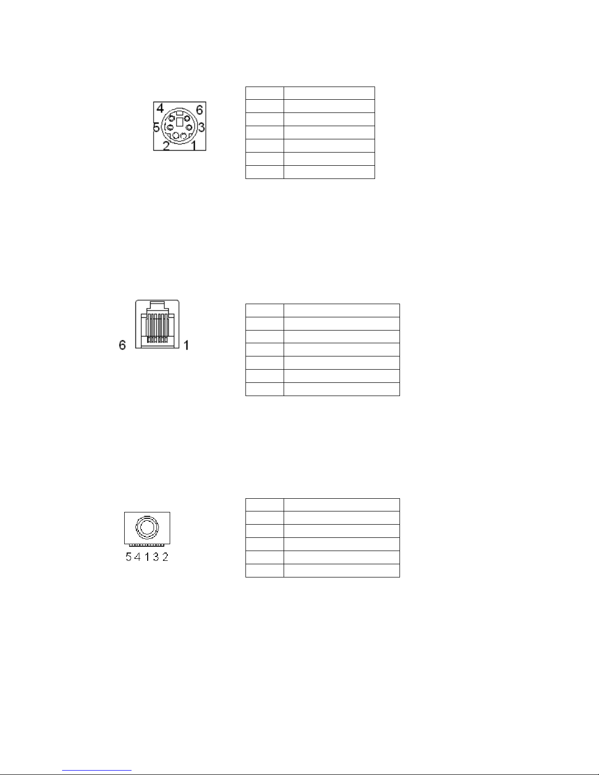
I. KB_MS1 (PS/2 Connector)
J. RJ11 Port
K. AUDIO_JACK (Audio Line Out)
Pin Definition
1 Keyboard Data
2 Mouse Data
3 GND
4 Mouse Clock
5 5V
6 Keyboard Clock
RJ11
Pin Definition
1 GND
2 GPIO-0
3 CASH Drawer Switch
4 12V
5 GPIO-1
6 GND
Audio Jack
Pin Definition
1 GND
2 Line Out (L)
3 AUDIO_JD
4 -ACZ_DET
5 Line Out (R)
Page 41
MP-3435 / MP-3432 System manual v
ersion 0.3
36
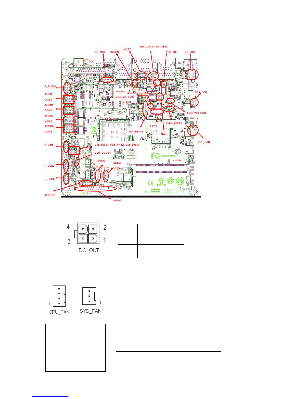
Jumper Setting
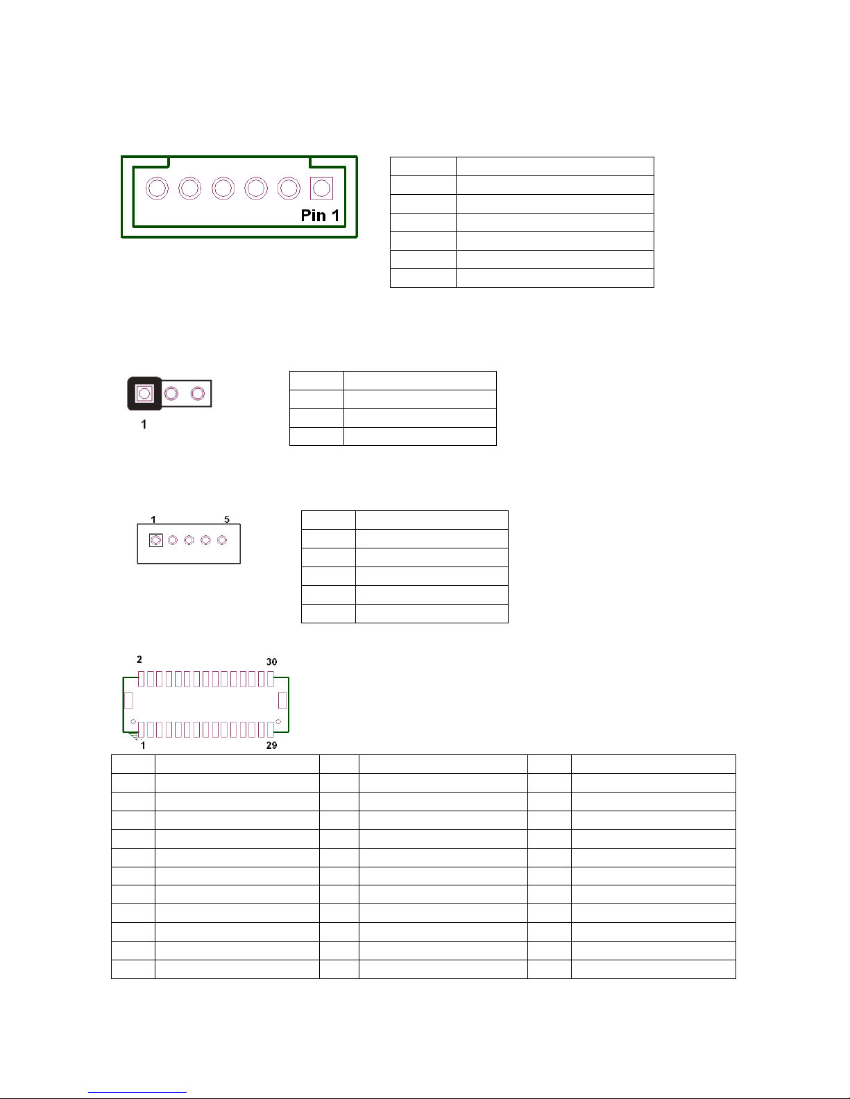
1. DC_OUT (12V for external/internal use, This connector is reserved for future use)
2. CPU_FAN (CPU FAN)
3. SYS_FAN (System FAN)
CPU_FAN:
Pin Definition
1 GND
2 +12V/RPM
control
3 RPM detect
4 RPM control
SYS_FAN:
Pin Definition
1 GND
2 +12V/RPM control
3 RPM detect
DC 12V OUT:
Pin Definition
1 GND
2 GND
3 12V
4 12V
Page 42
MP-3435 / MP-3432 System manual v
ersion 0.3
37
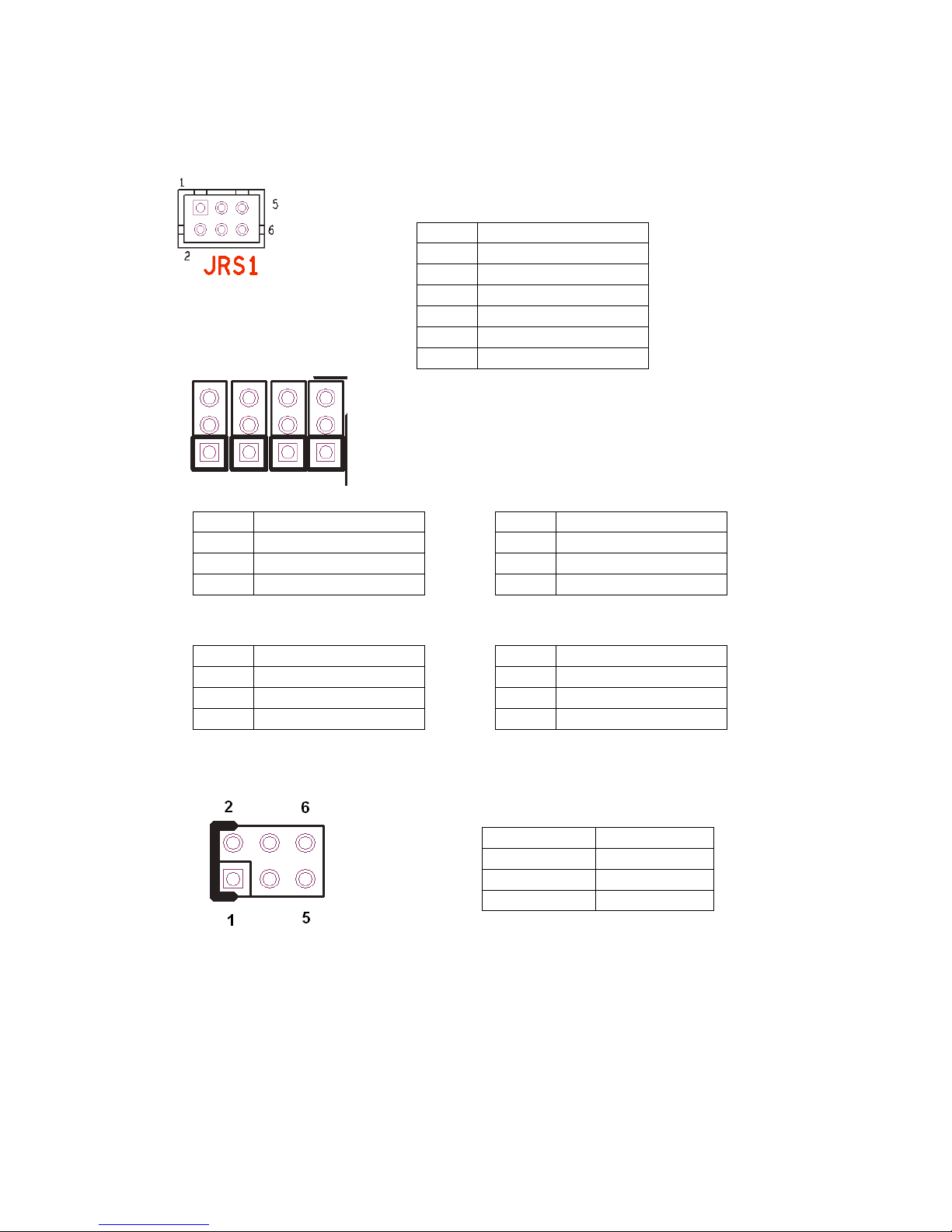
4. KB_MS2 (PS/2 Keyboard and PS/2 Mouse)
5. LVDS_PWR1 (LVDS 3V/5V selection)
6. INV_BRIG1 (Inverter with Box-header )
7, LVDS 18 bit Connector
Pin Definition Pin Definition Pin Definition
1 GND 12
Backlight Enable 23 LVDS Clock+
2 NC 13
GND 24 Backlight 5V
3 EDID Data 14 Backlight Controller 25 GND
4 GND 15
Data1+ 26 GND
5 EDID Clock 16
GND 27 Data26 NC 17
Data1- 28 LVDS Power 3.3V
7 GND 18
GND 29 Data2+
8 NC 19
GND 30 LVDS Power 3.3V
9 Data0+ 20
Backlight 5V
10 NC 21
LVDS Clock-
11 Data0- 22
Backlight 5V
KB_MS2:
Pin Definition
1 GND
2 KDAT
3 F_KDAT
4 KCLK
5 F_KCLK
6 5V
LVDS_PWR1: Default: 1-2
Pin Definition
1 3.3V
2 DC input
3 5V
INV_BRIG1:
Pin Definition
1 12V DC out
2 12V DC out
3 GND
4 Backlight Controller
5 Backlight Enable
Page 43
MP-3435 / MP-3432 System manual v
ersion 0.3
38
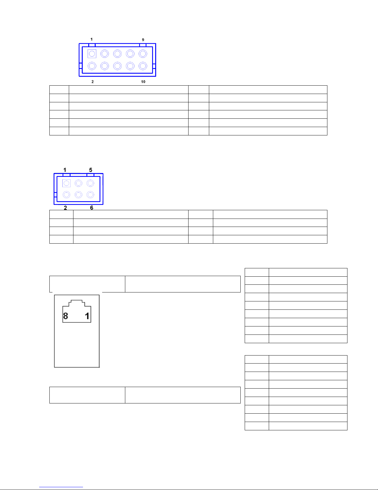
8. JRS1, JRS2, JRS3, JRS4, JRS5 (Only COM2 available for RS232,RS422 or RS485
selections)
JRS2, JRS3, JRS4, JRS5
9. JCOM1, JCOM2, JCOM3, JCOM4,JCOM5,JCOM6 for D-sub 9’s Pin 9 output
5V,12V or RI (COM4 output on RJ-45’s Pin1&2)
***PS: JCOM4 is pre-set as 5-6 short for 12V VFD customer display
JCOM5 is pre-set as 1-2 short for 5V built in LCM customer display
JCOM3 is pre-set as 1-2 short for 5v touch controller
10. COM1, COM3, COM5, COM6 (Serial Port with Box-header)
Default 1-2
Pin Definition
1 RS232
2 UART RXD
3 RS422
4 UART RXD
5 RS485
6 UART RXD
JRS2: Default 2-3 short
Pin Definition
1 RS485 D2 COM2 Pin 1
3 RS232 DCD
JRS3: Default 2-3short
Pin Definition
1 RS485 D+
2 COM2 Pin 2
3 RS232 RXD
JRS4: Default 2-3
Pin Definition
1 RS422 D2 COM2 Pin 4
3 RS232 DTR
JRS5: Default 2-3
Pin Definition
1 RS422 D+
2 COM2 Pin 3
3 RS232 TXD
Default 3-4 Short
Pin Definition
1-2 Short 5V
3-4 Short RI
5-6 Short 12V
Page 44
MP-3435 / MP-3432 System manual v
ersion 0.3
39
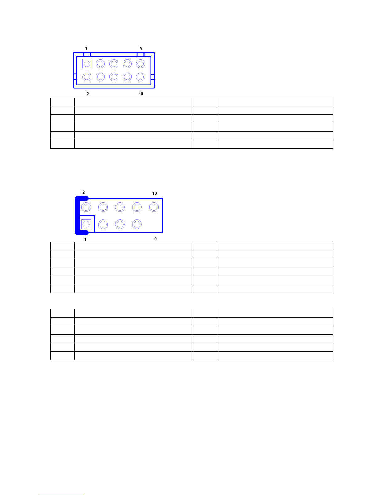
Pin Definition Pin Definition
1 DCD 2 DSR
3 RXD 4 RTS
5 TXD 6 CTS
7 DTR 8 RI/+5V/+12V
9 GND 10 RI/+5V/+12V
11. VFD_JR1 (VFD & RS232 Mode select)
Pin Definition Pin Definition
1 CTS4- 2 RTS43 Signal for PIN2 of COM4 port 4 Signal for PIN4 of COM4 port
5 RI4-/1_5V/12V_F 6 GND
***PS: JCOM4 is set to 5-6 short for 12V VFD display as default.
VFD Mode VFD_JR1[1-2], [3-5], [4-6] Short
JCOM4[5-6] Short
RS232 Mode VFD_JR1[1-3], [2-4] Short
JCOM4 [3-4] Short
Pin Definition
1 12V
2 12V
3 GND
4 GND
5 DTR
6 DSR
7 TXD
8 RXD
Pin Definition
1 RI
2 CTS
3 GND
4 RTS
5 DTR
6 DSR
7 TXD
8 RXD
COM4_USB1 Port
Page 45
MP-3435 / MP-3432 System manual v
ersion 0.3
40
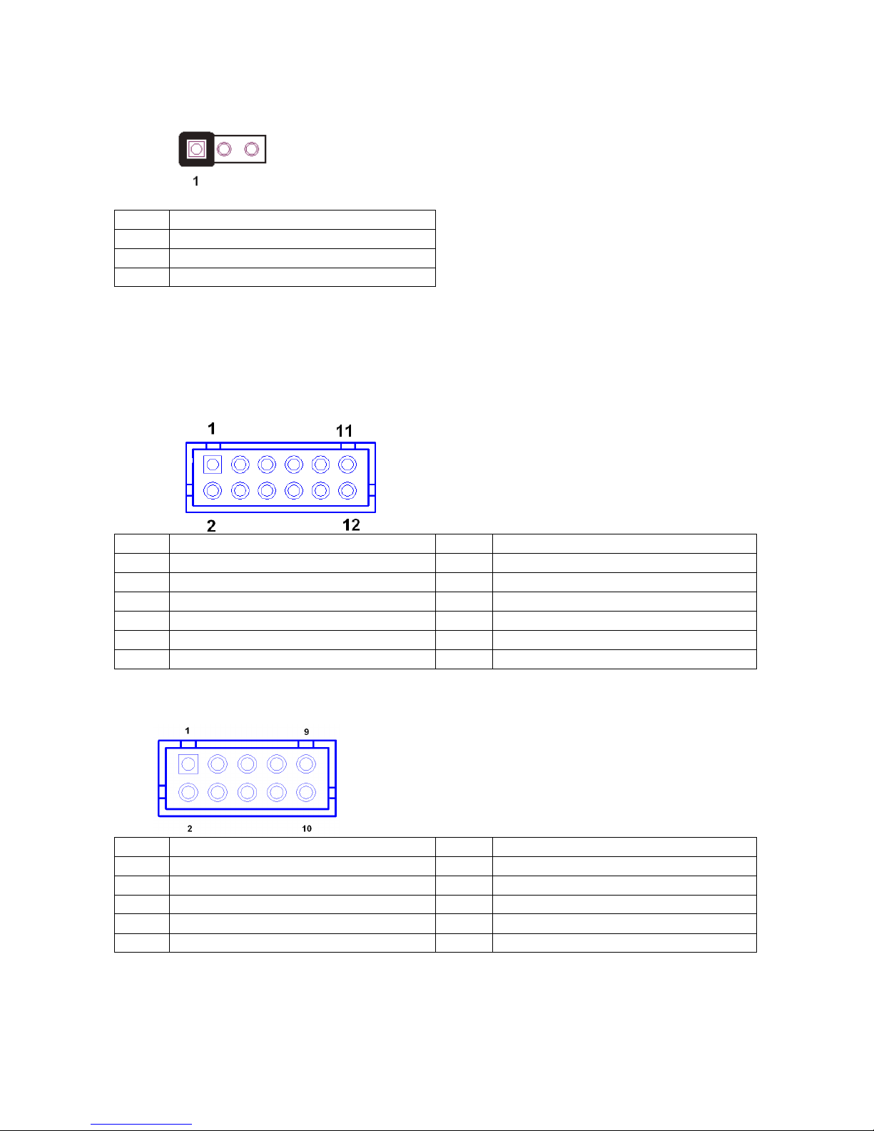
12. JFRONT (Front Panel Connector with Box-header)
Pin Definition Pin Definition
1 Stand-by LED 2 Power LED
3 Power Switch# 4 GND
5 LAN Action LED 6 Stand-by 5V
7 HDD LED# 8 VCC 5V
9 System Reset# 10 GND
13. F_USB1, F_USB2, (USB Pin-header)
Pin Definition Pin Definition
1 USB Power 5V 2 USB Power 5V
3 USB Dx- 4 USB Dy5 USB Dx+ 6 USB Dy+
7 GND 8 GND
9 NC 10 NC
F_USB3, (USB Pin-header)
Pin Definition Pin Definition
1 USB Power 5V 2 USB Power 5V
3 USB Dx- 4 NC
5 USB Dx+ 6 NC
7 GND 8 GND
9 NC 10 NC
Page 46
MP-3435 / MP-3432 System manual v
ersion 0.3
41
14. USB_PWR1, USB_PWR2, USB_PWR3 (Jumper for Stand-by ,5V or VCC 5V
selections)
Default 1-2 short
Pin Definition
1 VCC 5V
2 USB DC IN
3 Stand-by 5V
15. F_AUDIO (Front Audio Box-header)
Pin Definition Pin Definition
1 Amplifier Out_R+ 2 MIC_L
3 Amplifier Out_R- 4 MIC_R
5 GND 6 Line In_R
7 Amplifier Out_L+ 8 Line In_L
9 Amplifier Out_L- 10 Line In_JD
11 GND 12 MIC_JD
16. VGA2 (VGA Connector with Box-header)
Pin Definition Pin Definition
1 V-SYNC 2 H-SYNC
3 GND 4 GND
5 RED 6 GND
7 GREEN 8 DDC Clock
9 BULE 10 DDC Data
Page 47
MP-3435 / MP-3432 System manual v
ersion 0.3
42
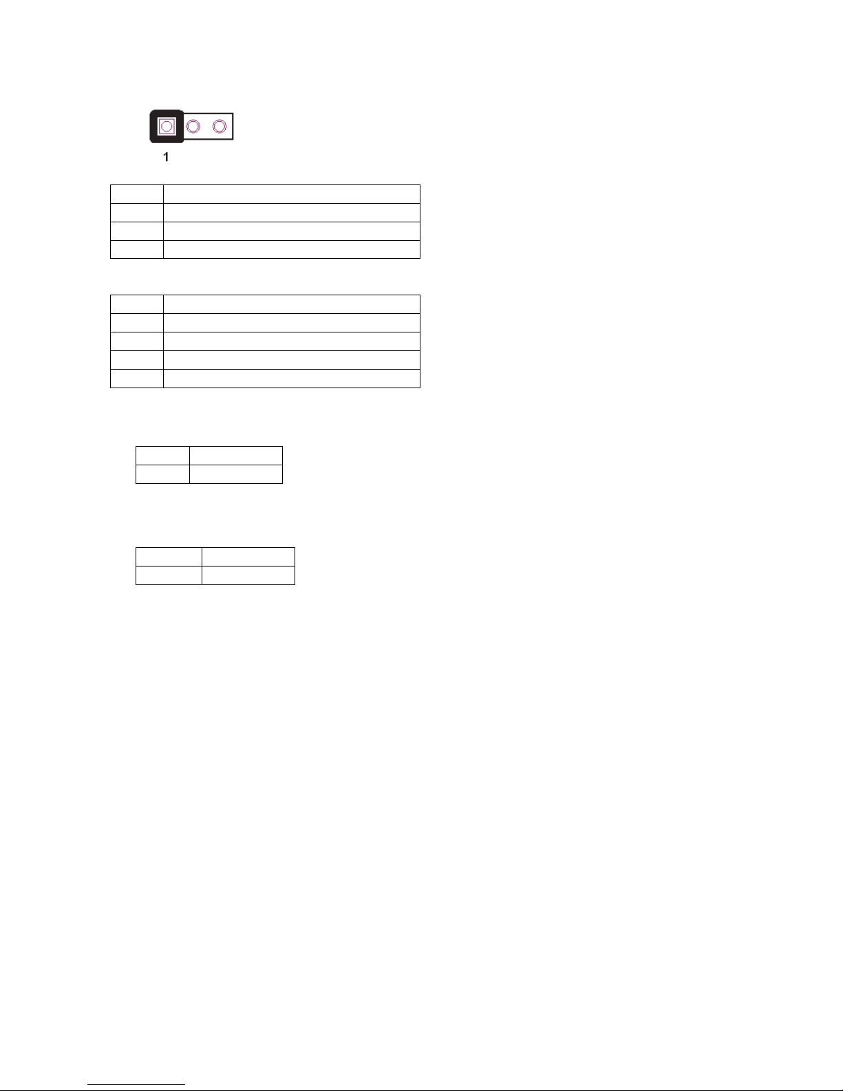
17. CLR_COMS1 (Clear CMOS Pin-header)
Default 2-3 short
Pin Definition
1 GND
2 Battery 3V
3 Battery 3V
18. SATAPW_1, SATAPW_2 (SATA HDD Power 5V & 12V)
Pin Definition
1 +12V
2 GND
3 GND
4 5V
19. LCDPWR_CON (LCD Power ON/OFF)
20. BKLTEN_CON (Back light Inverter Enable/Disable)
Default 1-2 Open
ON Short 1-2
OFF Open 1-2
Default 1-2 Open
Enable Short 1-2
Disable Open 1-2
Page 48

MP-3435 / MP-3432 System manual v
ersion 0.3
43
TTrroouubblleesshhoooottiinngg
Please note that the following troubleshooting guide is designed for people with strong computer
hardware knowledge such as System Administrators and Engineers.
Touch Panel Does Not Work
A) Check CMOS settings, COM3 needs to be “Enabled”.
B) Check if there are no conflicts between COM3 and any other devices.
C) Check if the ELO driver or the TouchKit driver has been properly installed. Or try to re-
install again (Please refer to the ELO driver installation or the TouchKit driver).
D) Check if the ELO controller or the TouchKit driver on COM3 has been detected during
the ELO driver or the TouchKit driver installation. If yes, then check if the flat cable from
the ELO touch screen or the TOUCHKIT touch screen has been properly connected to
the ELO controller or the TouchKit controller (Attention: Pin1 mark should be on the
same side as the ELO controller).
E) Check if the ELO controller Green LED is blinking?
If no, there is no DC+5V support for the ELO controller from the motherboard.
F) Touch screen controller could be defective or the touch panel could be defective.
ELO Touch Panel Cannot Calibrate Correctly
A) Please replace the ELO controller, and re-calibrate. If this works, change back to the
original ELO controller, and re-calibrate.
B) If the ELO touch panel still cannot calibrate correctly after changing to a new ELO
controller, the touch panel may be not installed properly or it could be defective.
Cannot Detect HDD
A) SATA cable is not connected properly to main board or it could be defective.
B) HDD power cable is not connected properly to the main board or it could be defective.
C) Check CMOS setup, set SATA HDD to Auto Detect.
D) On-board SATA port could be defective.
Page 49

MP-3435 / MP-3432 System manual v
ersion 0.3
44
PS/2 Keyboard Is Not Functioning Normally
A) Make sure the keyboard is properly connected to the PS/2 keyboard port before the
system is powered up. If the keyboard is connected after Windows2000 has been booted,
the keyboard will not work.
B) Check that the LED on the keyboard goes on then off after power on. If yes, the
keyboard is getting power correctly.
C) The main board could be defective.
LAN Is Not Functioning Properly
A) Check if the LAN driver is installed properly.
B) Check if there are any IRQ conflicts.
C) Check if the RJ45 cable is properly connected.
D) The on-board LAN chip could be defective.
COM1, COM2, COM5 Are Not Functioning Properly
A) Check if the I/O ports are enabled in the CMOS setup.
B) Check if there are any IRQ conflicts.
C) The main board or I/O cable could be defective.
Cash Drawer Port Is Not Functioning Properly
A) Make sure the pin assignment matches between the cash drawer and the RJ11 cash
drawer port.
B) Verify if the digit I/O port address and bit are correct.
C) The main board could be defective.
USB Device Is Not Functioning Properly
A) Ensure that the USB controller is “enabled” in the CMOS setup.
B) Ensure that the USB Legacy is “enabled” in the CMOS setup. (Windows 2000、Window
XP Professional)
C) Ensure that the USB Legacy is “Disabled” in the CMOS setup. (Embedded OS:
Windows XP Embedded、Window CE. NET、Linux RedHat 9)
 Loading...