

Page 1
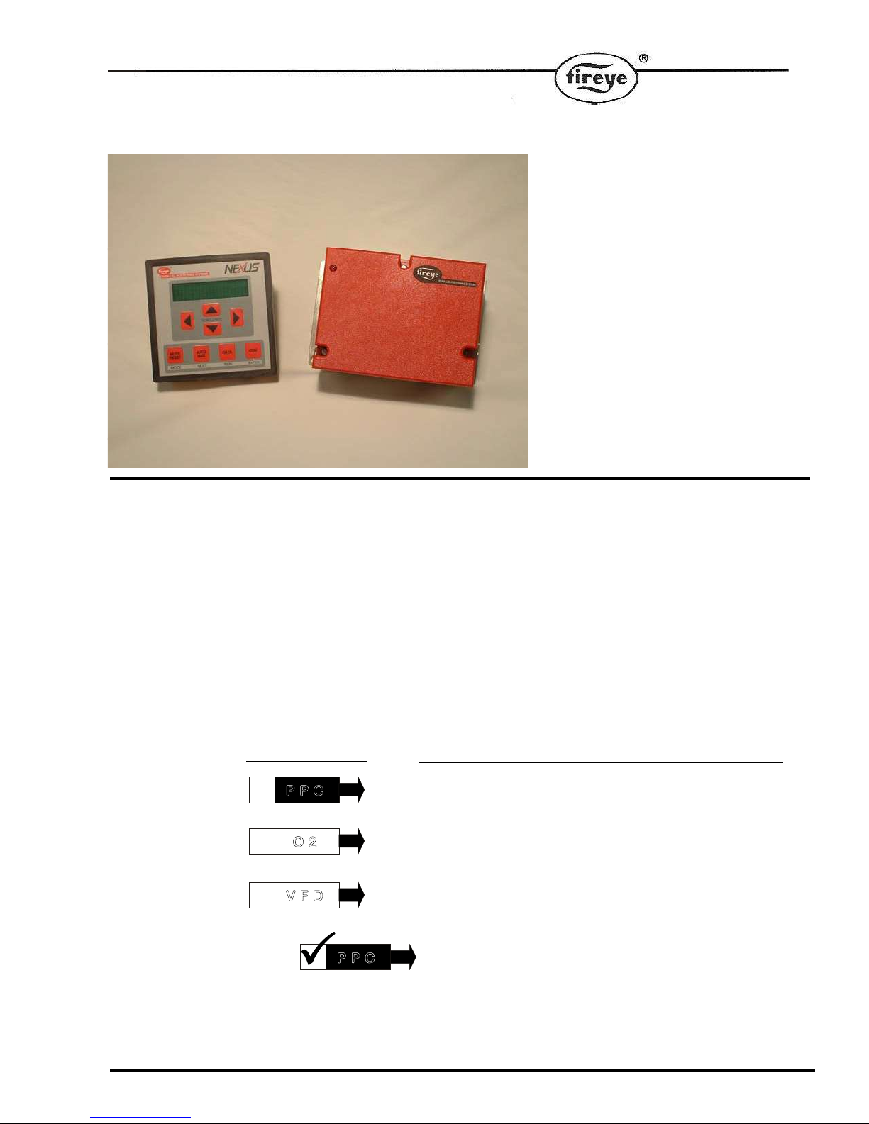
NXPG-6001
APRIL 8, 2013
PROGRAMMING
GUIDE
FOR
PPC6000
SERIES
DESCRIPTION:
This document supplies the commissioning engineer with sufficient information to make
appropriate setup and changes to the commissioning of the PPC6000.
NOTE: For additional information on Installation and Wiring information, please
refer to the complete installation manual - Fireye bulletin PPC-6001
For ease of navigation (see section 1.3.1), the symbols below will be used throughout
the Commissioning Process in this manual to indicate the correct application for each
commissioning OPTION, for use by the Commissioning Personnel.
A convenient check box has been added to the beginning of the symbols so that the
Commissioning Personnel can mark each appropriate option as it is completed.
SYMBOL MEANS:
Commissioning Personnel MUST execute this option
For Customers with O2 TRIM option, Commissioning
For Customers with VFD options, Commissioning Personnel
P P C
O 2
V F D
Personnel MUST ALSO execute this option
MUST ALSO execute this option
P P C
After each appropriate option parameter is
complete, CHECK THE BOX!
Page 2

The following items are covered in this manual:
1 COMMISSIONING THE CONTROL. ....................................................................................................... 5
1.1 General ..................................................................................................................................................... 5
1.2 Commissioning data ................................................................................................................................ 6
1.2.1 Option parameters ......................................................................................................................... 6
1.2.2 Setpoints........................................................................................................................................ 6
1.3 The Commissioning process. ................................................................................................................... 6
1.3.1 Navigation. .................................................................................................................................... 6
1.4 Using option set mode .............................................................................................................................. 7
1.4.1 Option parameter list ..................................................................................................................... 8
Option 00.1 - Site passcode (0 - 999) LV3 ................................................................................................ 8
Option 00.2 - Serial communications control address (0 - 15) LV3 .......................................................... 8
Option 00.3 - Reset hours run (0 - 1) LV3 ................................................................................................ 8
Option 00.4 – User program select (0 / 1) LV1 ......................................................................................... 8
Option 00.5 – Language select (0 / 1) LV1 ............................................................................................... 9
Option 00.6 – Remote / Local Control (0 - 2) LV3 ................................................................................... 9
Option 01.0 – Power Up Option (0 - 30) LV3 ........................................................................................... 9
Option 01.1 – Keyboard Auto/Manual enable (0 - 1) LV3 [Engineer’s Key 33] ..................................... 9
Option 01.2 – Fault Mute Input enable (0 - 2) LV3 ................................................................................ 10
Option 02.x – Drive Name LV3 .............................................................................................................. 11
Option 03.x – Drive Serial Number LV3 ................................................................................................ 12
Option 04.x – Drive Usage Information LV3 .......................................................................................... 13
Option 05.x – Drive Options LV3 ........................................................................................................... 13
Options 06.1-06.4 – Profile Naming LV3 ............................................................................................... 14
Options 07.x, 08.x– RESERVED ............................................................................................................. 14
Option 09.0 - Inverter control accuracy (0 / 1) LV3 ................................................................................ 14
Option 09.1 - Inverter error tolerance (0 / 1) LV3 ................................................................................... 14
Option 09.2 - Inverter closed loop gain (15 – 125%) LV3 ...................................................................... 15
Option 09.3 - Inverter stop time (0 – 100 seconds) LV3 ......................................................................... 15
Option 09.4 - Inverter acceleration time (0 –60 seconds recommended) LV3 ........................................ 15
Option 09.5 – VFD1 Speed Encoder Scaler (255 - 999) LV3 ................................................................. 15
Option 09.6 – VFD2 Speed Encoder Scaler (255 - 999) LV3 ................................................................. 16
Option 09.7- RESERVED ........................................................................................................................ 16
Option 09.8- RESERVED ........................................................................................................................ 16
Option 09.9- RESERVED ........................................................................................................................ 16
Option 14.0 – Primary Fault Relay (0-8) LV3 ......................................................................................... 16
Option 14.1 – Limit Relay (0-8) LV3 ...................................................................................................... 17
Option 14.2 – Oxygen and Flue Temperature Limit Relay (0-8) LV3 .................................................... 17
Option 15.0 - Modulation sensor input type (0 - 1) LV3 ......................................................................... 18
Option 15.1 – Modulation input decimal places (0 to 2) LV2 ................................................................. 19
Option 15.2 – Modulation input zero value (0 - 999 / 0.0 - 99.9 / 0.00 – 9.99) LV3 .............................. 19
Option 15.3 – Modulation input span value (0 - 999 / 0.0 - 99.9 / 0.00 – 9.99) LV3 ............................. 19
Option 15.4 – Setpoint control units (0 – 3) LV3 .................................................................................... 20
Option 15.5 - Boiler high safety limit (0 - 999 / 0.0 - 99.9 / 0.00 – 9.99) LV3 ....................................... 20
Option 15.6 – Modulation Time (0 – 120 seconds)* ............................................................................... 20
Option 15.7 – Bumpless Transfer (0 or 1)* LV3 ..................................................................................... 20
Option 15.8 – Low before Off (0 or 1)* LV3 .......................................................................................... 21
Option 16.1 – Go back to pilot (0-15) LV3 ............................................................................................. 21
Option 16.2 – Allow profile swap (0-16) LV3 ........................................................................................ 22
2
Page 3

Option 18.1 to 18.4 – Low Voltage Fail-safe Alarm / Lockout Inputs (0 – 360) LV3. .......................... 23
Option 19.1 to 19.4 – Fail-safe Alarm / Lockout Display Messages LV3. ............................................. 24
Option 20.0 – Set-point Select input (0 - 16) LV3 .................................................................................. 25
Option 20.1 – Boiler Shutdown input (0 - 16). LV3 ............................................................................... 25
Option 20.2 – Low Fire Hold input (0 - 16). LV3 .................................................................................. 25
Option 20.3 – Oxygen Trim Disable input (0 - 16). LV3 ....................................................................... 25
Option 20.4 – Ignition Wait input (0 - 16). ............................................................................................. 26
Option 20.5 – Purge Hold input (0 - 16). LV3 ........................................................................................ 26
Option 20.6 – Purge Time Start input (0 - 16). LV3 ............................................................................... 26
Option 20.7 – Analog Input 5 function (0 - 2). LV3 ............................................................................... 26
Option 21.0 – PID (setpoint) 1 enable (0 - 1) LV1 ................................................................................. 26
Option 21.1 – Set-point 1 control value (0 - 999 / 00.0 - 99.9 / 0.00 - 9.99) LV1 .................................. 26
Option 21.2 –Set-point 1 proportional band (0 - 999 / 00.0 - 99.9 / 0.00 - 9.99) LV1 ........................... 27
Option 21.3 – Set-point 1 integral time (0 – 99.9 minutes) LV1 ........................................................... 27
Option 21.4 – Set-point 1 derivative time (0 – 999 seconds) LV1 ......................................................... 27
Option 21.5 - Setpoint 1 control limit type (0 - 2) LV3 .......................................................................... 27
Option 21.6 - Setpoint 1 low limit control value (0 - 999 / 00.0 - 99.9 / 0.00 - 9.99) LV1 .................... 28
Option 21.7 - Setpoint 1 high limit control value (0 - 999 / 00.0 - 99.9 / 0.00 - 9.99) LV1 ................... 28
Option 21.8 – Remote Setpoint 1 zero (4ma) value (0 - 999 / 00.0 - 99.9 / 0.00 - 9.99) LV1 ................ 28
Option 21.9 – Remote Setpoint 1 span (20mA) value (0 - 999 / 00.0 - 99.9 / 0.00 - 9.99) LV1 ............ 28
Option 22.0 – PID (set-point) 2 enable (0 - 1) LV1 ................................................................................ 28
Option 22.1 – Set-point 2 control value (0 - 999 / 00.0 - 99.9 / 0.00 - 9.99) LV1 .................................. 28
Option 22.2 – Set-point 2 proportional band (0 - 999 / 00.0 - 99.9 / 0.00 - 9.99) LV1 .......................... 28
Option 22.3 – Set-point 2 integral term (0 – 999 seconds) LV1 ............................................................ 28
Option 22.4 – Set-point 2 derivative term (0 - 100) LV1 ....................................................................... 28
Option 22.5 - Setpoint 2 control limit type (0 - 2) LV3 .......................................................................... 29
Option 22.6 - Setpoint 2 low limit control value (0 - 999 / 00.0 - 99.9 / 0.00 - 9.99) LV1 .................... 29
Option 22.7 - Setpoint 2 high limit control value (0 - 999 / 00.0 - 99.9 / 0.00 - 9.99) LV1 ................... 29
Option 22.8 – Remote Setpoint 2 zero (4mA) value (0 - 999 / 00.0 - 99.9 / 0.00 - 9.99) LV1 ............... 29
Option 22.9 – Remote Setpoint 2 span (20mA) value (0 - 999 / 00.0 - 99.9 / 0.00 - 9.99) LV1 ............ 29
Option 23.0 – Warming Enable (0 or 1) LV1 ......................................................................................... 29
Option 23.1 – Warming Limit (0 - 999 / 00.0 - 99.9 / 0.00 - 9.99) LV1 ................................................ 29
Option 23.2 – Warming Time (0 to 999 minutes) LV1 .......................................................................... 30
Options 24.x - Sequencing: ................................................................................................................................. 30
Option 24.0 Sequence Slaves (number of boilers) (0-3) LV3................................................................. 31
Option 24.1 -24.3 Priority Number(s) LV3 ............................................................................................ 31
Option 24.4 - Reserved ............................................................................................................................ 31
Option 24.5 – Lead (master) Boiler Select Method LV3 ....................................................................... 32
Option 24.6 - Lag (slave) On Rate (0-100%) LV3 ................................................................................. 32
Option 24.7 - Lag (slave) On Delay (0-999 minutes) LV3 ..................................................................... 32
Option 24.8 - Lag (slave) Off Rate (0-100%) LV3 ................................................................................. 32
Option 24.9 - Lag (slave) Off Delay (0-999 minutes) LV3 .................................................................... 32
Option 30.0 – Oxygen probe interface serial number LV3 ..................................................................... 33
Option 30.4 – Flue and inlet sensor temperature units (0 – 1) LV3 ........................................................ 33
Option 30.5 - Oxygen input function (0/1) LV3 ...................................................................................... 34
Option 30.6 - Oxygen probe calibrate enable (0 – 2) LV3 ...................................................................... 34
Option 30.7 - Boiler transport delay (5 – 60 seconds) LV3 .................................................................... 34
Option 30.8 - Reset oxygen trim profile (0/1) LV3. ................................................................................ 35
Option 30.9 – Automatic trim commissioning (0 / 1) LV3 ..................................................................... 35
Option 31.0 - Limit Modulation Range (0 to 2) LV3 .............................................................................. 35
Options 31.1 to 31.4 - Trim Type for profiles 1 to 4 (0 to 2) LV3 .......................................................... 36
Option 32.0 - Trim limit default (0/1) LV3 ............................................................................................. 36
3
Page 4

Options 32.1 to 32.4 - Trim limits (0.0 – 25.0) LV3 ................................................................................ 36
Options 33.1 to 33.4 - Trim integral gain (0.0 – 99.9%) LV3.................................................................. 37
Option 34.0 - Trim proportional gain default (0/1) LV3 .......................................................................... 37
Options 34.1 to 34.4 - Trim proportional gain (0.0 – 99.9%) LV3 .......................................................... 37
Option 34.5 - Calculating and entering the flow values manually – optional LV3 ................................. 37
Option 35.0 – Inlet temperature sensor serial number LV3 ..................................................................... 41
Options 35.1 to 35.4-Hydrocarbon ratios of each fuel respectively (0.00 – 9.99) LV3 .......................... 41
Options 35.5 to 35.8-Calorific values of fuels/profiles 1 to 4 respectively (0.0 – 99.9) LV3 ................. 41
Option 35.9 - Boiler radiated heat loss (0.0 – 9.9%) LV3 ....................................................................... 42
Option 36.0 - Flue temperature alarm select (0/1) LV3 ........................................................................... 42
Options 36.1 to 36.4 - Flue temperature low alarm values (0 – 999) LV3 ............................................... 42
Options 37.1 to 37.4 - Flue temperature high alarm values (0 – 999) LV3 ............................................. 42
Option 38.0 - Oxygen alarm select (0 – 2) LV3 ....................................................................................... 43
Options 38.1 to 38.4 - Oxygen low alarm values at low fire (0.0 – 99.9%) LV3 .................................... 43
Options 39.1 to 39.4 - Oxygen low alarm values at high fire (0.0 – 99.9%) LV3................................... 43
Options 40.1 to 40.4 - Oxygen high alarm values at low fire (0.0 – 99.9%) LV3................................... 43
Options 41.1 to 41.4 - Oxygen high alarm values at high fire (0.0 – 99.9%) LV3 .................................. 43
Option 42.0 – Second Oxygen probe interface serial number LV3 ......................................................... 44
Option 42.1 – Second Oxygen probe calibration offset value (0 – 999) LV3 .......................................... 44
Option 42.2 – Second Oxygen probe calibration gain value (0 – 999) LV3 ............................................ 44
Option 42.3 – Second Oxygen probe calibrate enable (0 – 2) LV3 ......................................................... 45
Option 42.4 –Oxygen variation probe 1 to probe 2 LV3 ......................................................................... 45
Option 44.0 - Set real time clock (0/1) LV1 ............................................................................................ 45
Option 44.1 – Set Year (00 – 99) LV1 .................................................................................................... 45
Option 44.2 – Set Month (1 – 12) LV1 ................................................................................................... 45
Option 44.3 – Set Day (1 – 31) LV1 ....................................................................................................... 45
Option 44.4 – Set Hours (0 - 23) LV1 ..................................................................................................... 45
Option 44.5 – Set Minutes (0 - 59) LV1 .................................................................................................. 45
Option 44.9 – Reset Fault Log (0 - 1) LV3 ............................................................................................. 45
Option 45.0 - Erase / Restore enable (0 - 1) LV3 .................................................................................... 46
Option 45.1 - Erase command (0 - 5) LV3 .............................................................................................. 46
Option 45.2 - Restore command (0 - 999) LV3 ....................................................................................... 46
1.5 Commission ratio mode ......................................................................................................................... 47
1.5.1 Description .................................................................................................................................. 47
1.5.2 Using commission ratio mode ..................................................................................................... 47
1.5.3 Leaving commission ratio mode ................................................................................................. 48
1.6 Adjust ratio mode .................................................................................................................................. 49
1.6.1 Description .................................................................................................................................. 49
1.6.2 Entering adjust ratio mode .......................................................................................................... 49
1.6.3 Using adjust ratio mode .............................................................................................................. 50
1.6.4 Leaving adjust ratio mode ........................................................................................................... 51
1.7 Interrogating the software issue ........................................................................................................... 51
2 APPENDIX............................................................................................................................................. 52
2.1 Terminal Designation ............................................................................................................................ 52
2.2 Typical Wiring Diagram / BurnerLogix .............................................................................................. 53
2.3 Combustion Profile Setup Guideline.................................................................................................... 55
4
Page 5
1 Commissioning the control.
WARNING
This manual may cover more than one model from the PPC6000 series.
Check for additional information at the end of this chapter.
While the control is operating in commissioning mode or adjust ratio mode
certain safety checks cannot be performed by the control and therefore the
safety of the system operation is the sole responsibility of the
commissioning engineer.
Do not allow fuel to accumulate in the combustion chamber. If fuel is
allowed to enter the chamber for longer than a few seconds without
igniting, an explosive mixture could result.
If a flame failure occurs at any point the control will not attempt a re-start
until the fault is cleared. Before moving to the ignition position to attempt a
re-start the system will perform any selected pre-purge.
1.1 General
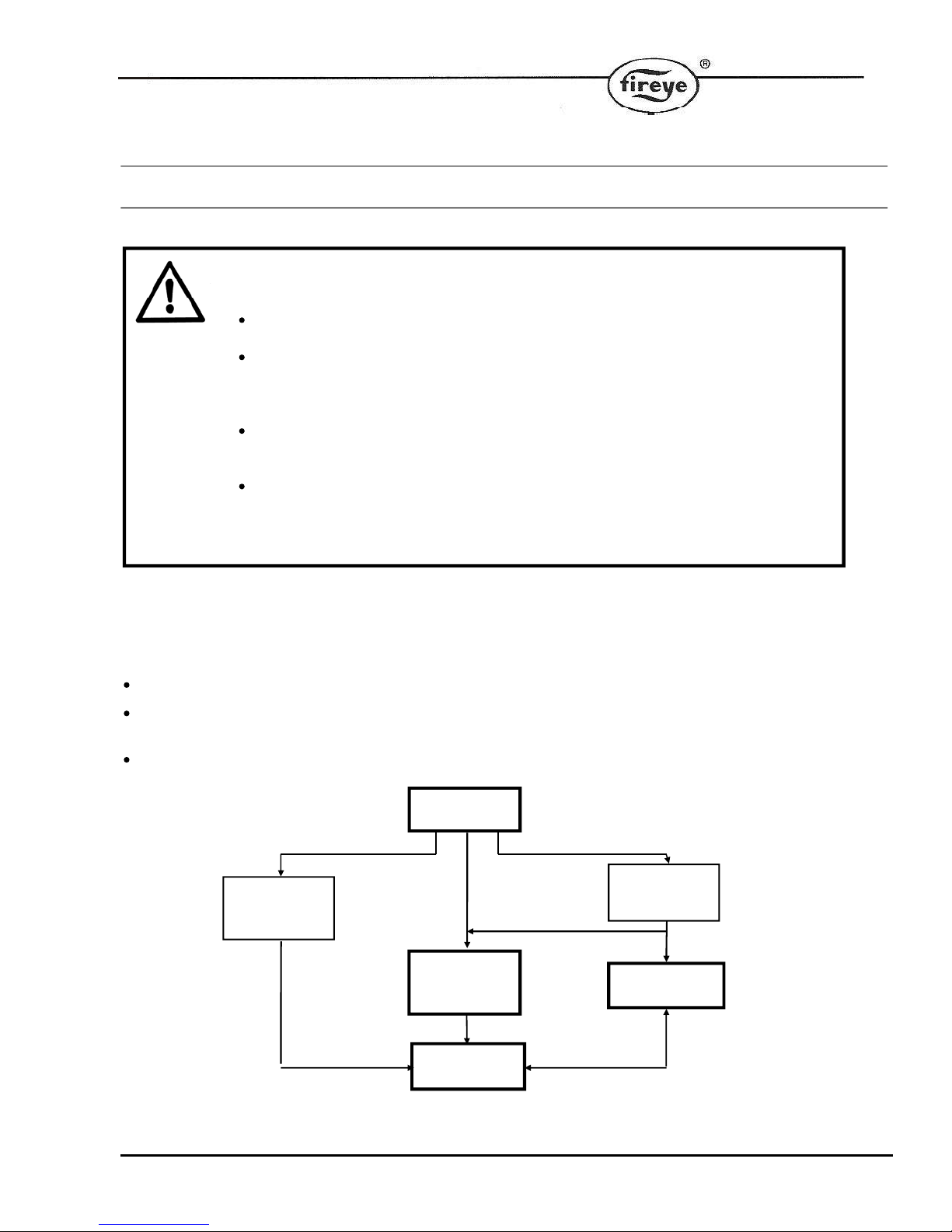
If any settings in the control are to be changed, it is necessary to enter a commission mode. Three passcodes
are available for this purpose, shown as LV1 (Level 1), LV2 (Level 2), and LV3 (Level 3) in this manual
Supplier passcode – LV3 – allows entry to all commissioning modes.
Adjust ratio passcode – LV2 -- allows adjustment of some option parameters and entry to adjust ratio
mode.
Site passcode – LV1 -- allows adjustment of some option parameters.
RUN
MODE
SITE
PASSCODE
LV1
<COM>
1
2
ADJUST
RATIO MODE
LV2
<MODE>
OPTION SET
MODE
<COM>
3
BURNER ON
SUPPLIER
PASSCODE
LV3
BURNER OFF
COMMISSION
RATIO MODE
<COM>
5
Page 6
1.2 Commissioning data
1.2.1 Option parameters
The PPC6000 series is configured by programming Option Parameters (memory registers), which describe the
configuration of the burner and the boiler. Option parameters are set and adjusted in Option Set mode, but it
may not be possible to adjust all of them if the burner is on.
1.2.2 Setpoints
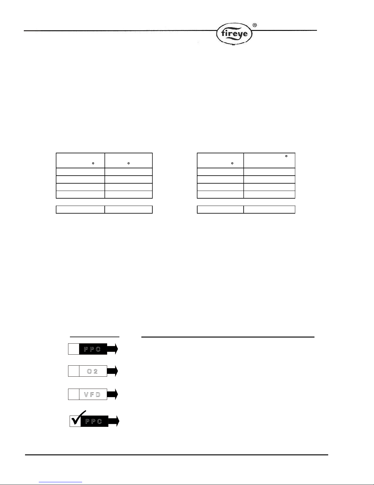
Setpoints contain information about required motor positions. There are four profiles (or tables) of setpoints. A
minimum of four positions (P0, P1, P2, and P3) MUST be entered for the PPC6000 to run in automatic.
)
Air position
( )
Profile 1 (Gas)
position (
2.1 1.9
2.1 88.9
24.6 30.6
21.3 25.8
76.8 85.6
Profile 2 (Oil)
CLOSE(P0)
PURGE(P1)
IGNITION(P2)
LOW FIRE(P3)
HIGH FIRE(Px)
Air position(
)
position( )
1.7 1.9
1.7 88.9
10.6 28.7
10.6 28.7
50.2 83.5
Up to 24 setpoints may be entered for each profile, including close, purge, and ignition.
New setpoints must be entered in commission ratio mode.
Existing setpoints may be modified in adjust ratio mode or commission ratio mode.
1.3 The Commissioning process.
1.3.1 Navigation.
The symbols below will be used throughout the Commissioning Process in this manual to indicate the correct
application for each commissioning OPTION, for use by the Commissioning Personnel.
A convenient check box has been added to the beginning of the symbols so that the Commissioning
Personnel can mark each appropriate option as it is completed.
SYMBOL MEANS:
Commissioning Personnel MUST execute this option
For Customers with O2 TRIM option, Commissioning Personnel
For Customers with VFD options, Commissioning Personnel MUST
P P C
O 2
V F D
P P C
6
MUST ALSO execute this option
ALSO execute this option
After each appropriate option parameter is complete,
CHECK THE BOX!
Page 7

1.3.1.1 Entering commission ratio mode
f
To enter commission ratio mode, turn the burner off. Once the burner has completely shut down, press the
key labeled COM and select the supplier passcode value using the UP/DOWN keys. The supplier passcode is
normally 2 sets of three numbers and is entered as shown below.
Run mode, burner of
COM
Supplier passcode 1
set of numbers
Supplier passcode 2
set of numbers
st
nd
ENTER
ENTER
If the entered passcode is correct, ‘P 0’ will be seen on the display. This represents the closed position
setpoint.
1.3.1.2 Changing from Commission / Adjust Ratio mode to Option Set mode
Commission / Adjust ratio mode
MODE
Option set mode
To enter option set mode, enter commission ratio mode or adjust ratio mode (see sections 1.3.1 or 1.6.2
respectively) and press the key labeled MODE.
1.3.1.3 Changing from option set to Commission / Adjust ratio modes
Option set mode
MODE
Commission ratio / Adjust ratio mode
1.3.1.4 Exiting from commission mode
To exit from any commission mode to run condition, press the key labeled RUN and then ENTER.
e.g.
Option set mode
ENTERRUN
Run mode
NOTE: Exiting from “full commissioning” mode at P3 or higher will erase any point above the displayed Px. If
this is undesirable, exit “full commissioning” mode at HIGH FIRE.
1.4 Using option set mode
Use the UP/DOWN keys to select the Option parameter to be adjusted.
Use the Scroll keys to navigate between Option numbers and the Option values.
Use the UP/DOWN keys to change the value of the option parameter. When the correct value is selected
then press the ENTER key to store the new value.
Set or adjust all of the parameters as required by moving between the parameters and adjusting as
detailed above.
7
Page 8
1.4.1 Option parameter list
CAUTION
Use extreme care when entering option parameters. Incorrect data entry could
cause a hazardous situation to occur.
It is possible that additional parameters may be present in the unit depending on
the application and/or supplier.
Note: Option parameters are marked with LV1, LV2, and LV3, which indicate what level passcode is
required. If, when using the supplier passcode (LV3), it is not possible to adjust the value of an option
parameter, then the burner must be turned off to make the adjustment.
Option 00.1 - Site passcode (0 - 999) LV3
This is a three digit passcode that will allow the site engineer or end-user to enter option set mode and adjust
a limited range of option parameters (those not marked with ‘LV2’ or ' LV3' in this section). This passcode can
be zero, in which case the user only needs to press the COM / ENTER key twice to enter option set mode with
limited access.
Option 00.2 - Serial communications control address (0 - 15) LV3
If the control is to be connected to other equipment via the serial communications interface, it must be given a
unique address using this option parameter. Additionally if more than one control unit is connected on the
CAN bus (for example to share a display), the units must all have unique addresses BEFORE THEY ARE
CONNECTED TO THE SAME CANbus.
Option 00.3 - Reset hours run (0 - 1) LV3
This option parameter allows the HOURS RUN display for all fuels to be reset to zero. To perform a reset, set
this option parameter to 1 and leave option set mode. When the burner begins to modulate, the HOURS RUN
display will be reset and the option parameter automatically returns back to 0.
Option 00.4 – User program select (0 / 1) LV1
This parameter may not be available. Where it is available, it allows the user to de-select the Fireye’s standard
modulation program, and select a user program. The user program may be modified using PC software to
change the controls behavior for non-standard applications.
The programmable system only allows access to non-safety related functions such as modulation, enabling /
disabling burner start-up and other similar functions. Only the user program can be modified, and Fireye’s
program can be re-selected at any time by changing this parameter back to zero.
Option 00.4
value
0 Run standard manufacturer modulation program. Controls PID, control limits, and
Meaning
8
Page 9

some Input / Output settings (see option parameters 20.0 to 29.9)
1 Run user program, if available.
Option 00.5 – Language select (0 / 1) LV1
DEFAULT: 0
This parameter may not be available. Where it is available, it allows the user to change the language used for
the display. Depending on spare memory and customer requirements, this option may only change the text
displayed to users in RUN mode, and not in COMMISSION mode – or all text can be changed to a second
language.
Option 00.5
Meaning
value
0 Operate with standard language (usually ENGLISH).
1 Operate with alternate language, at least in RUN mode – but possibly in other modes
depending on specification of the control.
Option 00.6 – Remote / Local Control (0 - 2) LV3
This parameter can be used to force the control to operate the boiler using setpoint 1 or 2, ignoring all remote
influences.
Option 00.5
Meaning
value
0 Normal (remote) operation. The boiler will be controlled to setpoint 1 or 2 depending
on options 20.0, 20.7 to 22.X. The setpoint and control limits can be overridden by
external influences such as analog / digital inputs and serial communications.
1 The boiler will be controlled to setpoint 1 as set in option parameter 21.X. Inputs that
would affect this such as the remote setpoint function on option parameter 20.7 and all
serial communications inputs are disabled.
2 The boiler will be controlled to setpoint 2 as set in option parameter 21.X. Inputs that
would affect this such as the remote setpoint function on option parameter 20.7 and all
serial communications inputs are disabled.
Option 01.0 – Power Up Option (0 - 30) LV3
This option can be used to modify the behavior of the control at power-up.
Option 01.0
value
0 Normal power-up. If no faults and fuel / burner selected, the burner will start.
1 Lockout. The burner will always lockout after a power-up. An F75 will be generated
which will require manual intervention to clear.
2 – 30 The control will power-up as normal, but wait for 2 to 30 seconds before checking the
digital inputs for fault conditions. This may be useful to prevent nuisance lockouts at
power-up due to water levels and plant interlocks. The control will remain in safety
shutdown (but not locked out) for this time.
Option 01.1 – Keyboard Auto/Manual enable (0 - 1) LV3 [Engineer’s Key 33]
DEFAULT: 1
9
Meaning
Page 10

It is possible to enable/disable the auto/man facility from the keyboard. Selecting a 0 will disable the operation
of the ‘auto/man’ function from the keyboard. Selecting a 1 will enable the operation of the ‘auto/man’ function
from the keyboard.
Option 01.2 – Fault Mute Input enable (0 - 2) LV3
The Fault Mute function is available via Comfire 2, on the keyboard and can also be selected to be from a
digital input. Selecting a non-zero value will enable the operation of the ‘Fault Mute’ function from the
corresponding digital input. It should be ensured that the digital input selected is not used for any other
function (option parameters 1.x, 16.x and 18.x, 20.x). MUST be connected as shown in section 3.6.11.
Please note any key/button providing a fault mute function must be mounted local to the burner.
Number entered in
parameter 01.2
0 Comview & Keyboard only NONE
1 Input 1 Input 1, PA5 to PA11 Low Voltage
2 Input 2 Input 2, PA6 to PA11 Low Voltage
3 Input 3 Input 3, PA7 to PA11 Low Voltage
4 Input 4 Input 4, PA8 to PA11 Low Voltage
Fault Mute Function Digital inputs used
Servomotor Shaft Position Warning
It is not possible to reposition the shaft of the servomotor other than to the factory settings of either
clockwise or counter clockwise. That is, the shaft flat (as viewed from the shaft end) will either be in the
9-12 o’clock or 6-9 o’clock position at PO (burner off). Using the “out of the box” settings will make
future replacement of servomotors easier.
Some motors have a clutch release to allow for the driven device to be rotated for inspection after
commissioning. It must be noted that releasing the clutch while the motor is powered will cause the
servomotor to drive back to the commissioned P0 position. Power should be removed if the clutch is
used for this purpose.
10
Page 11
P P C
Option 02.x – Drive Name LV3
CAUTION
The total electrical load for all connected servo motors must not exceed 40VA.
Each Drive connected to the system can be given a name which will than be shown on the text display, The
are a maximum of 10 drives (0 – 9), which can be connected, the names are set by option parameter 02.0 to
02.9.
The drives are displayed with the drive number first, then a three character label, such as ‘1GAS’, ‘2AIR’,
‘3AIR’ etc.
The permitted drive names are:
Number
entered in
parameter
02.X
0 N/A Not used N/A This drive will not be used.
1 FUE Fuel drive YES Generic fuel drive
2 GAS Fuel drive YES A gas drive
3 OIL Fuel drive YES An oil drive
4 CUP Fuel drive YES Cup speed for rotary cup burners
5 FGR Fuel drive NO Flue Gas Recirculation damper
6 PUM Fuel drive YES VFD controlled oil pump. Can be used for
7 WAS Fuel drive YES Waste fuel (combined fuel firing)
8 PRI Fuel drive YES Primary (flame shaping) air
9 FUE Fuel drive NO Generic fuel, but not trimmed.
10 AIR Air drive YES Main combustion air damper
11 FAN Air drive YES Main combustion air fan
12 SEC Air drive YES Secondary air (same as 10 apart from
13 AIR Air drive NO Generic Air, but not trimmed.
14 SLE Air drive YES Burner Sleeve
Drive
Name
Considered
as :
Trim if
selected :
Meaning
oil warming – see option parameter 9.0
name)
Two (or more) drives can be allocated the same name.
The number entered also tells the control information about the drive. If the number entered here is less than
10, the drive is considered a fuel. If the number is greater than or equal to 10, it is considered an air drive. This
only makes a difference when oxygen trim is enabled for a particular drive, since it determines the trim
direction. Selection of fuel trim or air trim is made with option parameters 31.1 to 31.4.
Primary air is considered a fuel drive since it is used for flame shaping and should normally track the fuel
valve.
11
Page 12
P P C
Option 03.x – Drive Serial Number LV3
CAUTION
The total electrical load for all connected servo motors must not exceed 40VA.
Each Drive
connected to the system has a unique serial number allocated to it during production testing. This number
cannot be changed and is used to uniquely identify each drive.
When the system is in commissioning mode the serial number of all the connected drives is read by the main
unit and displayed as a ‘list’ to allow the selection of the relevant serial number unit for each drive (0 – 9) to be
made.
Scrolling the list in an upward direction will scroll through all drive options available until ‘0, No Drive’ is
displayed. Enter this value to disconnect the specified drive from any hardware.
Scrolling the list in a downward direction will stop when the currently selected item is displayed, and the value
will stop flashing.
The display will show type information for each drive present (such as the torque rating of a servo), but the
commissioning engineer should be aware of which serial number servo is connected to which item on the
burner.
If the optional VFD daughterboard is fitted, four additional options are present:
Displayed Option Meaning
-a,VFD1:mA VFD channel 1 is used with a 4-20mA feedback
-b,VFD1:Hz VFD channel 1 is used with an encoder pulse (frequency) feedback
-c,VFD2:mA VFD channel 2 is used with a 4-20mA feedback.
-d,VFD2:Hz. VFD channel 2 is used with an encoder pulse (frequency) feedback.
Variable Speed Drive Selection:
Important Note: When selecting a VSD or variable frequency drive (VFD) consideration must be given to the
size and weight of the blower wheel. While a “fan” application is by nature a variable torque load, the inertia
(weight) of the blower wheel must be considered. Typical HVAC type drives do not speed up or slow down
large blower wheels with enough control to operate within the tolerance of the PPC or NX series control.
Therefore, a VSD (VFD) with some built in breaking capability, such as a constant torque drive, should be
used. At a minimum, if the drive has a constant torque setting, it must be enabled to minimize faults due to
drive hunting.
If a drive serial number is changed, any profiles using that drive will require re-commissioning. A ‘profile
invalid’ fault (see FAULT 64) will lock the burner out on an attempt to fire a profile which has had a previously
commissioned drive removed. The profile can be re-commissioned by using the NEXT / ENTER keys in
commission ratio mode to verify all points on the combustion curve.
12
Page 13

P P C
Option 04.x – Drive Usage Information LV3
The system will allow a maximum of four fuel / air profiles to be entered. Each drive (servo or VFD) can be
selected to operate for any, all or none of these profiles. This way the system can be programmed to use the
‘gas’ servo (for example) on a gas profile – but not an oil profile.
When the control is firing a profile that doesn’t use a specific drive, that drive can be disconnected or faulty
and the control will carry on working. So if the gas servo is broken, the burner can be run on oil, for example.
The number to be entered is a binary code:
+1 if the drive is used for profile 1,
+2 if the drive is used for profile 2,
+4 if the drive is used for profile 3,
+8 if the drive is used for profile 4.
This means that the number entered is from 0 to 15:
Number entered in parameter 4.X Drive X used for
profile(s)
0 NONE
1 1
2 2
3 1,2
4 3
5 1,3
6 2,3
7 1,2,3
8 4
9 1,4
10 2,4
11 1,2,4
12 3,4
13 1,3,4
14 2,3,4
15 1,2,3,4 (ALL)
If these parameters are changed after the burner has been commissioned, any profiles affected will need to be
re-commissioned. A drive selection fault will lock the burner out on an attempt to fire a profile which has had a
previously commissioned drive removed.
Example of use:
Option parameter 4.0 = 4
Option parameter 4.2 = 1
drive 0 used for profile 3 only.
drive 2 used for profile 1 only.
Option parameter 4.0 = 15
Option parameter 4.4 = 5
P P C
drive 4 used for profile 3 and profile 1 only.
Option 05.x – Drive Options LV3
13
drive 0 used for all profiles.
Page 14
This parameter is used to specify direction for each servo drive. This parameter has no effect for variable
speed drives (VFD). If this parameter is changed, affected profiles must be re-commissioned by a qualified
engineer.
Number entered in parameter 5.X Drive Options
0 Drive moves counter-clockwise (looking at output shaft).
1 Drive moves clockwise (looking at output shaft).
Options 06.1-06.4 – Profile Naming LV3
This selects the fuel associated with each profile (1 thru 4) to be displayed after the burner-on hours, e.g. 861
hours Profile 1 Gas, visible on the main display during operation.
Options 07.x, 08.x– RESERVED
V F D
Option 09.0 - Inverter control accuracy (0 / 1) LV3
Variable Speed Drive Selection:
Important Note: When selecting a VSD or variable frequency drive (VFD) consideration must be given to the
size and weight of the blower wheel. While a “fan” application is by nature a variable torque load, the inertia
(weight) of the blower wheel must be considered. Typical HVAC type drives do not speed up or slow down
large blower wheels with enough control to operate within the tolerance of the PPC or NX series control.
Therefore, a VSD (VFD) with some built in breaking capability, such as a constant torque drive, should be
used. At a minimum, if the drive has a constant torque setting, it must be enabled to minimize faults due to
drive hunting.
This parameter affects all inverters connected to the unit.
Option
Meaning
parameter 09.0
value
0 Low accuracy (normal setting). Control will be performed to within approximately
0.45Hz for a 0-50Hz system.
1
High accuracy. Control will be performed to within approximately
0.15Hz for a 0-
50Hz system.
Note: When using the high accuracy setting, the control may have difficulty with controlling the speed of the
inverter. If this occurs, use the low accuracy setting for reliable operation.
V F D
Option 09.1 - Inverter error tolerance (0 / 1) LV3
This option parameter affects all inverters connected to the unit.
14
Page 15
Option parameter 09.1
Meaning
value
0 Small tolerance (normal setting). The control will perform a non-volatile
lockout if the inverter positioning error exceeds
30 for 15 seconds or 55 for
3 second (units conform to those seen on the display).
1 Large tolerance. The control will perform a non-volatile lockout if the inverter
positioning error exceeds
55 for 3 seconds (units conform to those seen on
the display).
Note: Only use the large tolerance setting if an inverter error of up to 55 will not cause an unsafe combustion
condition to occur at any firing position.
V F D
Option 09.2 - Inverter closed loop gain (15 – 125%) LV3
DEFAULT: 100
This option parameter affects all inverters connected to the control.
For normal operation, use 100%. If the inverter control is unstable, reducing this value has the effect of
damping the inverter’s response as its speed approaches its setpoint.
V F D
Option 09.3 - Inverter stop time (0 – 100 seconds) LV3
Determines the minimum time between a burner shutdown and subsequent startup. Set this parameter to give
the inverter(s) sufficient time to stop before the burner restarts. This parameter will increase the time the
burner is held in status 5.
V F D
Option 09.4 - Inverter acceleration time (0 –60 seconds recommended) LV3
DEFAULT 30
The value entered for this parameter should be the time in seconds for the inverter(s) to move from minimum
to maximum speed.
The inverter(s) should also be able to move from maximum to minimum speed in the same time, if this is not
the case adjust the time in the inverter(s) to ensure the time to accelerate and de-accelerate are the same.
If this option parameter does not match the true VSD acceleration / deceleration times, drive positioning will be
compromised and position faults will be likely.
Note: This parameter can be set to values between 60 and 100, but this should only be used as a last resort if
required, and is not recommended. If a very slow inverter is used, care must be taken during commissioning
that UP / DOWN keys are not held for more than a few seconds. It is possible that the control could get out of
step with the inverter and cause a position fault during the commission process. This control is not designed to
work with inverters that take more than 60 seconds to drive from zero to maximum speed.
V F D
Option 09.5 – VFD1 Speed Encoder Scaler (255 - 999) LV3
When using encoder feedback for VFD1, this option should be programmed to ensure that the feedback signal
gives between 950 and 995 when the motor is at maximum speed (drive signal at 20mA). The value for the
parameter may be calculated using the following formula:
(Motor Max RPM x No of teeth on encoder)
15
= Scaler
Page 16

60
The value may need adjustment once the unit has been tested. Specifically, it must be ensured that the
feedback received never exceeds this value. In practice this may mean adding 2% to 5% to this value.
V F D
Option 09.6 – VFD2 Speed Encoder Scaler (255 - 999) LV3
When using encoder feedback for VFD2, this option should be programmed to ensure that the feedback signal
gives between 950 and 995 when the motor is at maximum speed (drive signal at 20mA). The value for the
parameter may be calculated using the following formula:
(Motor Max RPM x No of teeth on encoder)
= Scaler
60
The value may need adjustment once the unit has been tested. Specifically, it must be ensured that the
feedback received never exceeds this value. In practice this may mean adding 2% to 5% to this value.
Option 09.7- RESERVED
Option 09.8- RESERVED
Option 09.9- RESERVED
Option 14.0 – Primary Fault Relay (0-8) LV3
This option parameter assigns the primary faults to a specific relay. Relays 1 & 2 share a common connection.
Option parameter 14.0
Meaning Connection Details
value
0 Primary faults not assigned to any relay. N/A
1 Primary faults assigned to relay 1 Display, PR3(COM), PR1(NO),
PR2(NC). Low voltage or line
voltage.
2 Primary faults assigned to relay 2 Display, PR7(COM), PR5(NO),
PR6(NC). Low voltage or line
voltage.
3 Primary faults assigned to relay 3 Display, PR7(COM), PR9(NO),
PR8(NC). Low voltage or line
voltage.
4 Primary faults assigned to relay 4 Main Unit, PE4 (line voltage out).
5 No function. N/A
6 No function. N/A
7 Primary faults assigned to relay 7 Daughterboard, PZ15 – PZ16. LOW
VOLTAGE AND CURRENT ONLY.
8 Primary faults assigned to relay 8 Daughterboard, PZ18 – PZ17. LOW
VOLTAGE AND CURRENT ONLY.
16
Page 17

These relays MUST NOT be used to provide a safety function.
A relay can be used to indicate any combination of fault conditions from 14.0, 14.1 and 14.2 – this means that
one relay could be used for all faults. When used for an alarm function, the relay will de-energize when in the
fault condition, so an alarm bell would be wired in series with the normally closed contacts.
Option 14.1 – Limit Relay (0-8) LV3
This option parameter assigns the limits to a specific relay. Relays 1 & 2 share a common connection.
Option parameter 14.1
Meaning Connection Details
value
0 Limits not assigned to any relay. N/A
1 Limits assigned to relay 1 Display, PR3(COM), PR1(NO),
PR2(NC). Low voltage or line
voltage.
2 Limits assigned to relay 2 Display, PR7(COM), PR5(NO),
PR6(NC). Low voltage or line
voltage.
3 Limits assigned to relay 3 Display, PR7(COM), PR9(NO),
PR8(NC). Low voltage or line
voltage.
4 Limits assigned to relay 4 Main Unit, PE4 (line voltage out).
5 No function. N/A
6 No function. N/A
7 Limits assigned to relay 7 Daughterboard, PZ15 – PZ16. LOW
VOLTAGE AND CURRENT ONLY.
8 Limits assigned to relay 8 Daughterboard, PZ18 – PZ17. LOW
VOLTAGE AND CURRENT ONLY.
These relays MUST NOT be used to provide a safety function.
A relay can be used to indicate any combination of fault conditions from 14.0, 14.1 and 14.2 – this means that
one relay could be used for all faults. When used for an alarm function, the relay will de-energize when in the
fault condition, so an alarm bell would be wired in series with the normally closed contacts.
Option 14.2 – Oxygen and Flue Temperature Limit Relay (0-8) LV3
This option parameter assigns the limits to a specific relay. Relays 1 & 2 share a common connection.
17
Page 18

Option parameter 14.2
Meaning Connection Details
value
0 Flue Limits not assigned to any relay. N/A
1 Flue Limits assigned to relay 1 Display, PR3(COM), PR1(NO),
PR2(NC). Low voltage or line
voltage.
2 Flue Limits assigned to relay 2 Display, PR7(COM), PR5(NO),
PR6(NC). Low voltage or line
voltage.
3 Flue Limits assigned to relay 3 Display, PR7(COM), PR9(NO),
PR8(NC). Low voltage or line
voltage.
4 Flue Limits assigned to relay 4 Main Unit, PE4 (line voltage out).
5 No function. N/A
6 No function. N/A
7 Flue Limits assigned to relay 7 Daughterboard, PZ15 – PZ16. LOW
VOLTAGE AND CURRENT ONLY.
7 Flue Limits assigned to relay 8 Daughterboard, PZ18 – PZ17. LOW
VOLTAGE AND CURRENT ONLY.
These relays MUST NOT be used to provide a safety function. (See below)
A relay can be used to indicate any combination of fault conditions from 14.0, 14.1 and 14.2 – this means that
one relay could be used for all faults. When used for an alarm function, the relay will de-energize when in the
fault condition, so an alarm bell would be wired in series with the normally closed contacts.
P P C
Option 15.0 - Modulation sensor input type (0 - 1) LV3
The modulation sensor input caters for connection to a standard 0-5V or 4-20mA signal. When using a 420mA sensor, the control may be used to monitor the boiler high safety limit and perform a non-volatile lockout
if it is exceeded, additional external limits must still be in place to protect the boiler in case of a sensor failure.
Ensure that the links on the circuit board are set to correspond with the requirements of the sensor/signal
being used. Incorrect link setting may damage or destroy the units being connected.
18
Page 19
Option parameter
15.0 value
0 0 - 5V operation. Set the JP1 link to ‘OUT’. Set the JP3 link as
1 4 - 20mA operation. Set the JP1 link to ‘IN’. Set the JP3 link to’30V’.
2 4 - 20mA operation. Set the JP1 link to ‘IN’. Set the JP3 link to’30V’.
Meaning
required. This option is used to provide a 0 to 5 volt tracking input only.
The burner modulation will track the voltage applied, going to high fire
for 5 volts. There is no ‘measured value’, just a tracking setpoint.
Option parameters 15.0 to 15.5 are unavailable.
This option allows for connection to a 4 to 20mA pressure or
temperature sensor. The burner modulation will track the current
applied, going to high fire for 20mA and low fire for 4mA. If the current
goes outside the range, the burner will go to low fire. There is no
‘measured value’, just a tracking setpoint. Option parameters 15.0 to
15.5 are unavailable.
This option allows for connection to a 4-20mA measured value input
device such as a pressure or temperature sensor. The internal PID will
be used, if selected.
P P C
Option 15.1 – Modulation input decimal places (0 to 2) LV2
This parameter specified the number of decimal places to which the measured value and setpoint are
displayed. It also affects the scaling of the zero, span and safety limit – it is vital that this parameter is set
before parameters 15.2, 15,3 and 15.5
Option parameter
Meaning
15.1 value
0 Measure value and setpoint displayed with no decimal places. Range
of values is from 000 to 999.
1 Measure value and setpoint displayed with one decimal place. Range
of values is from 00.0 to 99.9.
2 Measure value and setpoint displayed with two decimal places. Range
of values is from 0.00 to 9.99.
P P C
Option 15.2 – Modulation input zero value (0 - 999 / 0.0 - 99.9 / 0.00 – 9.99) LV3
This value will normally be left at zero. It is the measured value to be displayed when the sensor connected is
at its minimum value.
If a 4-20mA sensor is used, this parameter should be set to the 4mA value (usually zero).
P P C
Option 15.3 – Modulation input span value (0 - 999 / 0.0 - 99.9 / 0.00 – 9.99) LV3
This value is the measured value to be displayed when the sensor connected is at its maximum value.
If a 4-20mA sensor is used, this parameter should be set to the 20mA value.
19
Page 20
P P C
Option 15.4 – Setpoint control units (0 – 3) LV3
This option selects the displayed units for setpoint and measured value.
Option parameter
Meaning
15.4 value
0 Show measured value as ‘PSI’.
1 Show measured value as ‘bar’.
2 Show measured value as ‘°F’
3 Show measured value as ‘°C’
P P C
Option 15.5 - Boiler high safety limit (0 - 999 / 0.0 - 99.9 / 0.00 – 9.99) LV3
If a 4-20mA sensor is used, this parameter may still be configured to give a lockout when a high limit is
reached. In this case, a value other than zero must be entered. Note: When a 4-20mA sensor is used,
external limits must be in place to protect the boiler in case of sensor failure.
Option 15.6 – Modulation Time (0 – 120 seconds)*
This option parameter sets the minimum time the burner will take to modulate from low to high fire or vice
versa. Note - only the modulation speed in AUTO mode is affected. The burner may modulate slower than this
setting if the drive speeds dictate this at any point in the range.
Option 15.7 – Bumpless Transfer (0 or 1)* LV3
This parameter affects the burner operation whilst in MANUAL mode only.
Option parameter
Meaning
15.7 value
0 When the burner comes back on after going off, it will remain at low
fire.
1 When the burner comes back on after going off, it will go to the last
modulation rate that it was set to in manual mode and stay there.
20
Page 21

Option 15.8 – Low before Off (0 or 1)* LV3
When set to 1, this parameter will change the way a normal controlled shutdown works.
Option parameter
Meaning
15.8 value
0 The burner will turn off immediately when it is expected / required to.
1 The burner will modulate down for up to 30 seconds (or until low fire is
reached) and then turn off.
Note: This function works for shutdowns caused by control limits for the currently selected setpoint and for
shutdowns caused by option parameter 20.1 (aux shutdown) only. Lockouts / shutdowns caused by the alarm
inputs in parameters 18.X will always work immediately.
Option 16.1 – Go back to pilot (0-15) LV3
This option allows a digital input to be configured to force the control to modulate down to low fire (if not
already there) and then move to the ignition position (P2). When at P2 the ignition-prove output (LFS) comes
on. The burner will continue to run at the ignition position until the digital input is removed.
This function can be used to prevent the burner from having to go off when the demand is low, meaning that it
is ready to immediately respond to a sudden increase in demand (no pre-purge required).
The digital input number to use for this function is entered as the option parameter value.
Number entered in parameter 16.1 Digital input used :
0 None.
1 Input 1, PA5 to PA11 Low Voltage
2 Input 2, PA6 to PA11 Low Voltage
3 Input 3, PA7 to PA11 Low Voltage
4 Input 4, PA8 to PA11 Low Voltage
5 Do not use.
6 Do not use.
7 Not a real input. Used for custom applications.
8 Not a real input. Used for custom applications
9 Not a real input. Used for custom applications
10 Not a real input. Used for custom applications
11 Not a real input. Used for custom applications
12 Not a real input. Used for custom applications
13 Not a real input. Used for custom applications
14 Not a real input. Used for custom applications
15 Not a real input. Used for custom applications
21
Page 22

Option 16.2 – Allow profile swap (0-16) LV3
This option performs exactly the same as 16.1 above except that when the control is at the pilot position, it will
allow a fuel profile change without forcing the burner to go off. When the fuel profile selection changes, the
ignition-prove output (LFS) will go off and the control will move all drives to the ignition (P2) positions on the
new fuel profile. The LFS will then come back on.
Number entered in parameter 16.1 Digital input used :
0 None. Do not allow profile swap.
1 Input 1, PA5 to PA11 Low Voltage
2 Input 2, PA6 to PA11 Low Voltage
3 Input 3, PA7 to PA11 Low Voltage
4 Input 4, PA8 to PA11 Low Voltage
5 Do not use.
6 Do not use.
7 Not a real input. Used for custom applications.
8 Not a real input. Used for custom applications
9 Not a real input. Used for custom applications
10 Not a real input. Used for custom applications
11 Not a real input. Used for custom applications
12 Not a real input. Used for custom applications
13 Not a real input. Used for custom applications
14 Not a real input. Used for custom applications
15 Not a real input. Used for custom applications
16 Always ON. Always allow profile swap.
22
Page 23

Option 18.1 to 18.4 – Low Voltage Fail-safe Alarm / Lockout Inputs (0 – 360) LV3.
These functions are all fail-safe and may be used to lockout or shutdown the burner.
The fault number generated always relates directly to the input that caused the fault (by going open circuit). Thus F1 comes from input 1,
F2 comes from input 2 and F4 comes from input 4.
The lockout functions themselves are activated by putting a number into option parameters 18.1 to 18.4 for
inputs 1 to 4. The number is a one, two or three digit number defined as follows (zero gives no function).
HUNDREDS
(fault type)
0 – This alarm will lockout the
burner and shows on the display
as ‘FXX’. Manual intervention (fault
mute) is required to restart the
burner once the fault condition has
cleared. The burner will lockout
within one second.
1 – This alarm will shutdown the
burner and show on the display as
‘FXX’. When the fault condition
clears, this fault will change to
‘CXX’ and the burner will restart
without manual intervention. The
burner will shutdown within three
seconds.
2 – This alarm is for indication only.
It will appear on the display as
‘LXX’ but will not stop the burner
operating. The limit will operate
within three seconds.
3 – This operates the same as
selection 1 in this column, but the
fault will be generated when the
input closes. This should not be
used for any safety function
because if the wire breaks, it
cannot be detected.
4 to 9 are spare and can’t be
selected.
4 to 9 are spare and can’t be
selected.
4 to 9 are spare and can’t be
selected.
TENS
(fuel type)
0 or 1 – Fault will be active for
any fuel selection (including no
fuel selected at all).
2 – Fault will be active only
when the currently selected
profile fires GAS.
3 – Fault will be active only
when the currently selected
profile fires OIL.
4 – Fault will be active only
when there is a fuel profile
currently selected (either firing
GAS or OIL).
All other values will work like
selection 1 (including zero). 5
to 9 are spare so new
functions can be added later.
All other values will work like
selection 1 (including zero). 5
to 9 are spare so new
functions can be added later.
All other values will work like
selection 1 (including zero). 5
to 9 are spare so new
functions can be added later.
UNITS
(burner status type)
0 or 1 – Fault will be active
regardless of the current burner
status (i.e. all the time).
2 – Fault will be active after the
fan has started, the air pressure
switch has made and the drives
have made their purge positions
(i.e. once pre-purge starts). Not
active during post purge.
3 – Fault will be active after prepurge has finished (i.e. drives
moving to the ignition position).
Not active during post purge.
4 – Fault will be active after pilot
ignition has started (status 11
onwards). Not active during post
purge.
5 – Fault will be active after
main ignition has started (status
13 onwards). Not active during
post purge.
6 – Fault will be active after the
drives have reached their low
fire positions and the burner is
ready to modulate (status 16).
Not active during post purge.
All other values will work like
selection 1 (including zero). 7
to 9 are spare so new
functions can be added later.
23
Page 24

Option
Digital Input Number / Terminals Fault number
parameter
number
18.1 Input 1 - PA5 to PA11, LOW VOLTAGE F1 or L1
18.2 Input 2 – PA6 to PA11, LOW VOLTAGE F2 or L2
18.3 Input 3 – PA7 to PA11, LOW VOLTAGE F3 or L3
18.4 Input 4 – PA8 to PA11, LOW VOLTAGE F4 or L4
To set input 2 to give a high gas pressure lockout you might enter 25 (025) into option parameter 18.2. This
will give a lockout when gas is selected and the main valve is open.
To set input 1 to give a second low water lockout you would enter 11 (or 1) into option parameter 18.1.
To set input 3 to give a high water alarm you would set 211 (or 200 or 210 or 201) in option parameter 18.3.
Option 19.1 to 19.4 – Fail-safe Alarm / Lockout Display Messages LV3.
The lockout functions are completely separate from the lockout messages. The messages are chosen from a
list of 32 possible items using option parameters 19.1 to 19.4 (for inputs 1 to 4). These are the default
messages, but at least some of them can be modified using serial communications and a PC.
Option parameter
19.X value
0 Alarm Input Open
1 Low Water
2 Extra Low Water
3 High Water
4 High Gas Pressure
5 Low Gas Pressure
6 High Oil Pressure
7 Low Oil Pressure
8 High Oil Temp.
9 Low Oil Temp.
10 Low Atom. Media
11 High Temperature
12 Low Temperature
13 High Pressure
14 Low Pressure
15 Panel Switch Open
16 High Stack Temp.
17 Fan Interlock
18 End Switch Open
19 Oil Interlock
20 Gas Interlock
21 to 31 (spare)
Meaning
24
Page 25
CAUTION
The product allows for customization of various non-safety critical functions
including the modulation control. The option parameters shown below relate to
the default modulation control function programmed in the control at the factory.
To verify this has not been replaced by an application specific function check with
the equipment supplier and / or check option parameter 00.4, if available.
Option 20.0 – Set-point Select input (0 - 16) LV3
This option parameter allows for a digital input to be used to select between modulation setpoint sets 1 and 2
(see option parameters 21.0 and 22.0 onwards). Select 0 to always give setpoint 1. A value of 16 will
permanently select setpoint 2.
Digital Input Numbers Digital input used :
0 None. Always reads OFF.
1 Input 1 - PA5 to PA11, LOW VOLTAGE
2 Input 2 – PA6 to PA11, LOW VOLTAGE
3 Input 3 – PA7 to PA11, LOW VOLTAGE
4 Input 4 – PA8 to PA11, LOW VOLTAGE
5 Do not use.
6 Do not use.
7 Not a real input. Used for custom applications.
8 Not a real input. Used for custom applications
9 Not a real input. Used for custom applications
10 Not a real input. Used for custom applications
11 Not a real input. Used for custom applications
12 Not a real input. Used for custom applications
13 Not a real input. Used for custom applications
14 Not a real input. Used for custom applications
15 Not a real input. Used for custom applications
16 Always reads ON.
Option 20.1 – Boiler Shutdown input (0 - 16). LV3
A high level on the input specified here will cause the boiler to go off and stay off until it is removed. No fault /
alarm is generated. The input numbers are as specified in option parameter 20.0 above.
Option 20.2 – Low Fire Hold input (0 - 16). LV3
A high level on the input specified here will cause the boiler to go to low fire and stay there until it is removed.
The input numbers are as specified in option parameter 20.0 above.
Option 20.3 – Oxygen Trim Disable input (0 - 16). LV3
A high level on the input specified here will cause the oxygen trim function to switch off (if it is selected) until it
is removed. The input numbers are as specified in option parameter 20.0 above. See option parameter 30.5.
25
Page 26

Option 20.4 – Ignition Wait input (0 - 16).
A high level on the input specified here will prevent the burner from igniting. The drives stay at their ignition
positions, but the light up sequence will not start until this input is removed. The input numbers are as
specified in option parameter 20.0 above.
Option 20.5 – Purge Hold input (0 - 16). LV3
A high level on the input specified here will prevent the burner moving on past pre-purge. The drives stay at
their purge positions, until this input is removed. The input numbers are as specified in option parameter 20.0
above.
Option 20.6 – Purge Time Start input (0 - 16). LV3
A high level on the input specified here will prevent the pre-purge time from starting. The drives stay at their
purge positions, until this input is removed and the specified pre-purge time has elapsed. The input numbers
are as specified in option parameter 20.0 above.
Option 20.7 – Analog Input 5 function (0 - 2). LV3
This parameter allows analog input 5 (the second modulation input) to perform specific functions.
Option parameter
Digital input used :
20.7 Value
0 This input does nothing.
1 Remote tracking input. If the control is in AUTO modulation mode
accepting remote inputs, and a valid 4-20mA signal is applied, the
control will modulate so as to track this input. 4mA = Low fire, 20mA =
High fire. If the signal goes below 3.5mA or above 21mA, this mode will
be cancelled and normal PID modulation will resume.
2 Remote Setpoint 1 Input. If the control is in AUTO modulation mode
accepting remote inputs, the value of setpoint 1 can be overridden when
a valid 4-20mA signal is applied to this input. The zero and span are set
in option parameters 21.8 and 21.9. If deviation limits are set (see option
parameter 21.5), then the high and low control limits will also move with
the setpoint. If the signal goes below 3.5mA or above 21mA, this mode
will be cancelled and normal setpoint 1 value will be applied.
Option 20.8 – Digital Input - Lead Boiler Select (1 - 4). LV3
This parameter selects the digital input (1-4), which selects this boiler as lead boiler.
P P C
Option 21.0 – PID (setpoint) 1 enable (0 - 1) LV1
This option parameter is used to select setpoint 1.
P P C
Option 21.1 – Set-point 1 control value (0 - 999 / 00.0 - 99.9 / 0.00 - 9.99) LV1
26
Page 27

This is the control value used in the PID control loop for setpoint 1. When the control is in auto mode, the PID
control loop will modulate the boiler to maintain the measured value at the same level as set by this parameter.
P P C
Option 21.2 –Set-point 1 proportional band (0 - 999 / 00.0 - 99.9 / 0.00 - 9.99) LV1
This is the width of the proportional band that is used by the PID control loop for setpoint 1. If the setpoint was
5.00 bar, and this term was set to 1.00, then the proportional band would be from 4.00 to 5.00 bar. A
measured value of 4.00 bar would give high fire, and 5.00 would give low fire, assuming no integral or
derivative terms were entered.
A value of 0 means no proportional band – the burner would stay at high fire until the setpoint is reached, then
drop to low fire. Proportional control is therefore needed to prevent the measured value from overshooting.
Option 21.3 – Set-point 1 integral time (0 – 99.9 minutes) LV1
This is the integral time used in the PID control loop for setpoint 1. It may be set to any value from 0 to 999,
seconds. If a value of 0 is entered the integral function is disabled, otherwise the time entered is the number of
minutes the control will take to give an additional modulation change equal to that currently given by the
proportional term. The lower the number (apart from zero), the more affect the integral function has. A large
number will cause the integral term to act very slowly.
Integral control is required for the burner to accurately reach its setpoint.
Option 21.4 – Set-point 1 derivative time (0 – 999 seconds) LV1
This is the derivative time used in the PID control loop for setpoint 1. It may be set to any value from 0 to 999.
A value of zero will disable the derivative function. A non-zero value will have the effect of ‘advancing’ the
modulation rate change caused by a constantly changing measured value by the number of seconds given. A
low value will have little effect; a large value will cause a large effect.
Derivative control is seldom needed for boilers, but can improve the response of the modulation system to
sudden load changes. Too much can cause control instability.
Option 21.5 - Setpoint 1 control limit type (0 - 2) LV3
This option parameter defines the control limit type for setpoint 1. The control limits are used to automatically
turn the burner off when it is not needed, and bring it back on when it is needed.
Option parameter
Meaning
21.5 value
0
No limits. The burner will run until another method is used to switch it
off.
1
Absolute limit. The values entered in option parameters 21.6 and
21.7 are the actual limit values.
2
Deviation limit. The values entered in option parameters 21.6 and
21.7 represent a deviation (i.e. offset) from the setpoint 1 control value.
This means that if the setpoint control value is changed, the limits are
automatically changed correspondingly.
27
Page 28

Option 21.6 - Setpoint 1 low limit control value (0 - 999 / 00.0 - 99.9 / 0.00 - 9.99) LV1
If the boiler is off due to a controlled shutdown, this parameter defines the measured value at which the boiler
will be turned on again.
Option 21.7 - Setpoint 1 high limit control value (0 - 999 / 00.0 - 99.9 / 0.00 - 9.99) LV1
If the boiler is on and firing, this parameter defines the measured value at which the boiler will be turned off via
a controlled shutdown.
Option 21.8 – Remote Setpoint 1 zero (4ma) value (0 - 999 / 00.0 - 99.9 / 0.00 - 9.99) LV1
This is the zero value for the remote setpoint function specified by option parameter 20.7.
Option 21.9 – Remote Setpoint 1 span (20mA) value (0 - 999 / 00.0 - 99.9 / 0.00 - 9.99) LV1
This is the span value for the remote setpoint function specified by option parameter 20.7.
Option 22.0 – PID (set-point) 2 enable (0 - 1) LV1
This option parameter is used to select setpoint 2.
Option 22.1 – Set-point 2 control value (0 - 999 / 00.0 - 99.9 / 0.00 - 9.99) LV1
This is the control value used in the PID control loop for setpoint 2. When the control is in auto mode, the PID
control loop will modulate the boiler to maintain the measured value at the same level as set by this parameter.
Option 22.2 – Set-point 2 proportional band (0 - 999 / 00.0 - 99.9 / 0.00 - 9.99) LV1
This is the width of the proportional band that is used by the PID control loop for setpoint 2. If the setpoint was
5.00 bar, and this term was set to 1.00, then the proportional band would be from 4.00 to 5.00 bar. A
measured value of 4.00 bar would give high fire, and 5.00 would give low fire, assuming no integral or
derivative terms were entered.
A value of 0 means no proportional band – the burner would stay at high fire until the setpoint is reached, then
drop to low fire. Proportional control is therefore needed to prevent the measured value from overshooting.
Option 22.3 – Set-point 2 integral term (0 – 999 seconds) LV1
This is the integral time used in the PID control loop for setpoint 2. It may be set to any value from 0 to 999,
seconds. If a value of 0 is entered the integral function is disabled, otherwise the time entered is the number of
seconds the control will take to give an additional modulation change equal to that currently given by the
proportional term. The lower the number (apart from zero), the more affect the integral function has. A large
number will cause the integral term to act very slowly.
Integral control is required for the burner to accurately reach its setpoint.
Option 22.4 – Set-point 2 derivative term (0 - 100) LV1
This is the derivative time used in the PID control loop for setpoint 2. It may be set to any value from 0 to 999.
A value of zero will disable the derivative function. A non-zero value will have the effect of ‘advancing’ the
modulation rate change caused by a constantly changing measured value by the number of seconds given. A
low value will have little effect; a large value will cause a large effect.
28
Page 29

Derivative control is seldom needed for boilers, but can improve the response of the modulation system to
sudden load changes. Too much can cause control instability.
Option 22.5 - Setpoint 2 control limit type (0 - 2) LV3
This option parameter defines the control limit type for setpoint 2. The control limits are used to automatically
turn the burner off when it is not needed, and bring it back on when it is needed.
Option parameter
Meaning
22.5 value
0
No limits. The burner will run until another method is used to switch it
off.
1
Absolute limit. The values entered in option parameters 22.6 and
22.7 are the actual limit values.
2
Deviation limit. The values entered in option parameters 22.6 and
22.7 represent a deviation (i.e. offset) from the setpoint 1 control value.
This means that if the setpoint control value is changed, the limits are
automatically changed correspondingly.
Option 22.6 - Setpoint 2 low limit control value (0 - 999 / 00.0 - 99.9 / 0.00 - 9.99) LV1
If the boiler is off due to a controlled shutdown, this parameter defines the measured value at which the boiler
will be turned on again.
Option 22.7 - Setpoint 2 high limit control value (0 - 999 / 00.0 - 99.9 / 0.00 - 9.99) LV1
If the boiler is on and firing, this parameter defines the measured value at which the boiler will be turned off via
a controlled shutdown.
Option 22.8 – Remote Setpoint 2 zero (4mA) value (0 - 999 / 00.0 - 99.9 / 0.00 - 9.99) LV1
If the boiler is on and firing, this parameter defines the measured value at which the boiler will be turned off via
a controlled shutdown.
Option 22.9 – Remote Setpoint 2 span (20mA) value (0 - 999 / 00.0 - 99.9 / 0.00 - 9.99) LV1
If the boiler is on and firing, this parameter defines the measured value at which the boiler will be turned off via
a controlled shutdown.
Option 23.0 – Warming Enable (0 or 1) LV1
This parameter allows a warming function to be applied to the boiler, and makes option parameters 23.1 and
23.2 available. If zero is entered, no warming limit is applied.
Option 23.1 – Warming Limit (0 - 999 / 00.0 - 99.9 / 0.00 - 9.99) LV1
If, when the burner starts up and reaches modulation, the measured pressure / temperature value is lower
than that specified here, the control will hold the boiler at low fire until the value specified is reached. The
29
Page 30

control will hold the boiler at low fire (in status 15) indefinitely unless a non-zero time has been entered in
option parameter 23.2.
Note : If during normal modulation, the measured value falls below this limit having once been above it, the
warming function will not be re-applied. The warming function is only applied on a burner start-up.
Option 23.2 – Warming Time (0 to 999 minutes) LV1
This parameter specifies a maximum time to hold the burner at low fire for, before ignoring the warming limit
and allowing normal modulation.
Additionally, when the burner goes off (for any reason other than power interruption), and the measured value
falls below the warming limit, the warming function will not be activated again until this time has passed.
NOTE: Further parameters (up to 29.9) may be available here if they are part of a users program or
non-standard manufacturers program.
Options 24.x - Sequencing:
Sequencing (lead/lag) is managed by using the “setpoint select” function internally to choose between Setpoint
1 and Setpoint 2 via the communications bus between PPC6000’s. The “lead” or “master” boiler controls the
“lag” or “slave” boiler(s) by switching them from setpoint 2 (“lag stand by” or “banking”) to the setpoint 1 values,
and turns on based on Option 24.6 (lag on delay) value. The lead boiler will override the modulation rate of the
last lag boiler to come on and cause it to modulate in unison with the lead (master) boiler. If both the lead
(master) boiler and last lag (slave) boiler remain above the Option 24.6 value another lag (slave) boiler will be
started after Option 24.7 (lag (slave) on delay) value has expired. Other lags that are on will remain at high fire
until the last lag is turned off. At this point, the next lag boiler will begin to modulate with the lead (master) and
so on until the lead (master) is carrying the load. The sequence in which boilers are turned on is set in Option
24.1-24.3 via communications addresses of each PPC6000. When a lead (master) boiler is deselected as lead
(master) and Option 24.0 has not been changed to 0, the boiler remains as lead (master) until a new lead
(master) takes control. Once the new lead (master) takes control, the previous lead (master) may be turned off
based on the demand and Option 24.1-24.3 settings.
If the lead (master) boiler is turned off, or fails to come on within three minutes, while operating as the lead,
sequencing will be disabled and all lag (slave) boilers will revert to their own PID settings. Should a lag boiler
fail to come on within three minutes, or the PPC6000 is faulted, sequencing will immediately call for the next
lag in the priority list.
If the lead (master) boiler is switched to manual modulation it will remain as lead bringing on lag (slave) boilers
as required. This will allow the operator to “base load” a lead boiler if required.
The PPC6000 can be the “master” (lead) boiler in a system that has PPC5000 or NX3100/4100 series as the
communications message are the same. The PPC6000 cannot be controlled by the PPC5000 or NX3100/4100
series controls as a boiler.
Stand by or Banking values
The “lag stand by” or “banking” temperature or pressure is entered as PID 2 or Setpoint 2 values however,
options 22.2, 22.3, 22.4 (the P, I and D) values are unnecessary as the burner will start and remain at low fire
until the “lag stand by” or “banking” cut out is reached. These values will be entered by;
1. Setting option parameter 22.0 to 1 (Enable Setpoint 2)
30
Page 31

2. Setting option parameter 22.1 to the desired setpoint value when in stand by.
3. Setting option parameter 22.5 to 1 (Absolute Value)
4. Setting option parameter 22.6 to the desired cut in value when in stand by.
5. Setting option parameter 22.7 to the desired cut out value when in stand by.
For example: If the normal operating setpoint is 100 PSI, and the desired stand by pressure is 75 PSI. The
setup would be:
Option Parameter Setting
22.0 1
22.1 75
22.5 1
22.6 75 (cut in or minimum pressure)
22.7 80 (cut out or maximum pressure)
NOTE: When using sequencing, setpoint 2 is unavailable for use with any digital input unless the boiler is
removed from sequencing completely.
Option 24.0 Sequence Slaves (number of boilers) (0-3) LV3
This option is set to 1, 2 or 3 in each PPC6000 to equal the number of lag “slave” boilers in the system. Once
set, option parameters 24.1, 24.2, and 24.3 will become available. If the value is set to 0 the boiler will be
taken out of sequencing and operate on its own PID. OPTION PARAMETER 00.6 MUST BE SET TO 0 FOR
SEQUENCING TO OPERATE
Option 24.1 -24.3 Priority Number(s) LV3
The order in which boilers sequence on is entered as the communication address(s) of the boilers in Options
24.1, 24.2 and 24.3. The first to be turned on will have a priority number one above that of the lead boiler.
For example: If the communications address of the four boilers were 1, 2, 3, and 4 (set in Option 0.2), boiler 1
master (lead), with the following entered in Options 24.1-24.3
Option parameter
Comms. Address Boiler
24.x value
24.1 2 2
24.2 3 3
24.3 4 4
The sequencing order would be boiler 2, 3 and 4. If boiler 2 were set to lead via Option 24.5, the order would
be boiler 3, 4 and 1. Setting boiler 3 to master (lead), the order would be boiler 4, 1 and 2. Other sequencing
orders can be achieved by changing the communications address entered in Options 24.1-24.3.
Note: Communications addresses should be changed while the boilers are not in sequencing (more
than one boiler on) so as not to disrupt operation.
Option 24.4 - Reserved
31
Page 32

Option 24.5 – Lead (master) Boiler Select Method LV3
This option parameter selects the lead (master) boiler via the keypad, digital input or communications (Comfire
2). The values are:
0 = Not lead, operates on own PID or as commanded by master (lead)
1 = lead (master) via Keypad
2 = lead (master) via digital input. (Digital Input Selected via Option 20.8)
3 = lead (master) via communications such as Comfire 2.
Note: When a lead (master) boiler is deselected as lead (master) and Option 24.0 has not been
changed to 0, the boiler remains as lead (master) until a new lead (master) takes control. Once the new
lead (master) takes control, the previous lead (master) may be turned off based on the demand and
Option 24.1-24.3 settings.
Option 24.6 - Lag (slave) On Rate (0-100%) LV3
This value determines the firing rate of the lead (master) boiler at which the first and all subsequent slave(s)
(lag) boilers come on. The slave(s) (lag) boiler(s) will be delayed in coming on by the time set in Option
parameter 24.7. At this point, the lead (master)and the will begin to modulate in unison. If the lead (master)
and modulate above this point, the next as determined by priority number (Option 24.1, 24.2, 24.3) will be
turned on. When more than one boiler is on, the master and last slave will modulate in unison while the other
slaves are held at high fire.
Option 24.7 - Lag (slave) On Delay (0-999 minutes) LV3
This option sets the time delay between the modulation rate of the lead (master) boiler (and last boiler on if
any) exceeding the value set in Option 24.6 and the next being turned on.
Option 24.8 - Lag (slave) Off Rate (0-100%) LV3
When the lead (master) boiler and last boiler modulate below this modulation rate and exceed the value set in
Option 24.9, the last turned on will be turned off. At this point, the lead (master) and the previous (if any)
turned on will begin to modulate in unison until they together are below this setting. This will continue until only
the lead (master) boiler remains on.
Option 24.9 - Lag (slave) Off Delay (0-999 minutes) LV3
This option sets the time delay between the modulation rate is at or below the value set in Option 24.8 and the
last turned on being turned off. This also sets the time delay between successive slaves (lag) being turned off
should the modulation rate stay below the setting in Option 24.8.
32
Page 33
O 2
Option 30.0 – Oxygen probe interface serial number LV3
Each CANbus device connected to the system has a unique serial number allocated to it during production
testing. This number cannot be changed and is used to uniquely identify each device.
When the system is in commissioning mode the serial number of all the connected devices is read by the main
unit and displayed as a ‘list’ to allow the selection of the relevant serial number unit to be made.
Scrolling the list in an upward direction will scroll through all oxygen probe interface options available until ‘0,
nothing’ is displayed. Enter this value to disconnect the specified device from any hardware.
Scrolling the list in a downward direction will stop when the currently selected item is displayed, and the value
will stop flashing.
The display will show type information for each device present (such as ‘O2 probe’), but the commissioning
engineer should be aware of which serial number device is being used for which function.
O 2
Option 30.1 - Oxygen probe calibration offset value (0 – 999) LV3
This option parameter is only available if option 30.0 is non-zero.
This option parameter must be set to the calibration offset value that is specified with the probe supplied.
O 2
Option 30.2 - Oxygen probe calibration gain value (0 – 999) LV3
This option parameter is only available if option 30.0 is non-zero.
This option parameter must be set to the calibration gain value that is specified with the probe supplied.
O 2
Option 30.3 - Oxygen probe calibration gas concentration (0.00 – 9.99%) LV3
This option parameter is only available if option 30.0 is non-zero.
This option parameter must be set to the percentage oxygen concentration of the calibration gas used if the
probe is to be calibrated using a reference gas (see option parameter 30.6). The range of this parameter is
0.00 - 9.99%.
O 2
Option 30.4 – Flue and inlet sensor temperature units (0 – 1) LV3
This option parameter is only available if option 30.0 is non zero.
This option parameter must be set to select the units for display of both temperatures on either
C or F.
Option parameter
30.4 value
0
1
C. The temperature value will be displayed in C.
F. The temperature value will be displayed in F.
Please note that temperature limits MUST be set in the correct units.
33
Meaning
Page 34
O 2
Option 30.5 - Oxygen input function (0/1) LV3
This option parameter can only be set above 1 if option 30.0 is non zero.
Using this option parameter, it is possible to configure the oxygen input for a monitoring function or trim
function. The two functions are explained below:
Option parameter
Meaning
30.5 value
0
Monitor only. The oxygen value is only used to provide a display of
the measured oxygen level.
1
Closed loop trim. The oxygen value is used to provide both a display
of the measured oxygen level and a feedback signal for closed loop
trim control function of the PPC6000 series control.
O 2
Option 30.6 - Oxygen probe calibrate enable (0 – 2) LV3
This option parameter is only available if option 30.0 is non-zero.
This option parameter must be used when calibrating the oxygen probe. There are three possible values:
Option parameter
Meaning
30.6 value
0
No calibrate. This is the normal operating condition, where the probe is used to
measure the oxygen concentration in the flue.
1
Calibrate in air. The probe will be calibrated for 'offset' at the normal
atmospheric oxygen concentration.
2
Calibrate in reference gas. The probe will be calibrated for 'gain' in a reference
gas with a nominal oxygen concentration the level specified in option parameter
30.3 (typically 3.0%).
Once this calibration has been successfully completed the values in 30.1 and 30.2 will be automatically
updated.
O 2
Option 30.7 - Boiler transport delay (5 – 60 seconds) LV3
Boiler transport delay is the time taken for 'gas' to travel from the burner to the oxygen probe. This delay
varies with burner fire rate.
In order for the oxygen trim control loop to be stable, this parameter must be set accurately to the transport
delay of the boiler when at low fire. This option may be set between 5 and 60 seconds inclusive.
To measure the transport delay, ignite the burner and enter adjust ratio mode. Select the low fire setpoint
and allow time for the flue oxygen reading to settle. Once the oxygen reading is steady, make a step
change to the fuel/air ratio and start a timer. As soon as the measured oxygen reading begins to change,
stop the timer. Set the option parameter to the recorded timer value in seconds.
Automatic trim commissioning (option 30.9) will attempt to set this automatically. However the value must
be checked by the engineer.
34
Page 35
O 2
Option 30.8 - Reset oxygen trim profile (0/1) LV3.
This option parameter allows the learnt trim profile to be reset. If the option is set to 1 any learnt profile
currently held in memory will be reset and the trim drives will return to their commissioned positions for the
corresponding modulation position. Once the profile has been reset this option parameter will automatically be
reset to 0.
O 2
Option parameter
Option 30.9 – Automatic trim commissioning (0 / 1) LV3
Meaning
30.9 value
0 Not selected.
1
Perform automatic trim characterization. The control will attempt to
characterize the burner profile by calculating flow values and selecting oxygen
setpoints to match the currently commissioned points.
Automatic trim commissioning will be performed under the following conditions:
An oxygen probe is fitted and fully operational
The control is in adjust ratio mode.
A hydrocarbon ratio has been entered for the current fuel (see option
parameters 36.5 – 36.8).
O 2
By default, the control modulates the burner between the set-points P
Option 31.0 - Limit Modulation Range (0 to 2) LV3
(low fire) and Ph (high fire), where Ph is
3
the last set-point entered in commission ratio mode. If oxygen trim is fitted, it is not possible for any drive
position to be trimmed lower than point P
(low fire) or higher than point Ph (high fire). Basically, you can’t take
3
fuel or air off at low fire, and you can’t add fuel or air at high fire.
This option parameter allows the engineer to overcome this limitation in one of two ways.
Firstly, the modulation range of the burner can be limited so that the burner may only modulate between points
(one set-point above low fire) and P
P
4
this limitation, each drive may be trimmed between the points P
over-fire or under-fire the burner but a degree of trim may still be achieved at high and low fire. Note that this
option may reduce the turn down of the boiler.
Another option, allows the control to adaptively adjust the modulation rate so that the required amount of trim
can be applied. The turn down of the boiler will not normally be limited because the high and low fire positions
of the trimmed drives will still be attained.
35
(one set-point below high fire). Since oxygen trim is not affected by
h-1
and Ph. This means that it is not possible to
3
Page 36
Option parameter
31.0 value
0 Modulation not limited. Burner modulates from P3 to Ph.
1 Normal modulation range limited to P4 to P
2 Modulation not limited, unless required for trim. Burner modulates from P3 to Ph,
Meaning
Oxygen trim works over full range from P
to Ph, but may not be able to apply
3
trim at high fire, or low fire – depending on trim direction.
The burner always modulates to the desired modulation rate, which may limit
the system’s ability to maintain the desired oxygen value.
always.
h-1
Oxygen trim works over full range from P
and high fire – limited by P
and Ph.
3
to Ph, and can apply extra trim at low
3
This setting is useful when there is extra capacity (usually air flow) available for
the burner, but otherwise it will reduce the turn-down ratio of the boiler.
but modulation will be adjusted (limited) to accommodate oxygen trim.
Oxygen trim works over full range from P
to Ph.
3
This setting allows oxygen trim be perform fully at all modulation positions, but
may limit the displayed modulation value. The power output (and therefore turndown ratio) should not be much affected though because the trim drives will still
operate over the whole modulation range.
O 2
Options 31.1 to 31.4 - Trim Type for profiles 1 to 4 (0 to 2) LV3
These option parameters determine the type of oxygen trim applied to profiles 1 to 4. These parameters are
used together with the parameters entered in option parameters 2.0 to 2.9 to determine which drives are
trimmed, and in which direction.
Parameter Meaning
31.1 Trim Type for profile 1.
31.2 Trim Type for profile 2.
31.3 Trim Type for profile 3.
31.4 Trim Type for profile 4.
Parameter value in
Meaning
31.X
0 No Trim. Do not apply oxygen trim when running on this profile.
1 Air Trim. Trim ‘Air’ drives when running on this profile (see option parameters 2.0
to 2.9.)
2 Fuel Trim. Trim ‘Fuel’ drives when running on this profile (see option parameters
2.0 to 2.9.)
O 2
Option 32.0 - Trim limit default (0/1) LV3
O 2
Options 32.1 to 32.4 - Trim limits (0.0 – 25.0) LV3
Option 32.0 is only available if option 30.5 (oxygen input function) has been set for closed loop oxygen trim.
It is possible for the system to trim the air or fuel drives up to a maximum deviation of ±25.0% of the total air or
fuel flow for the chosen trim drives.
36
Page 37
If option 32.0 is set to 0, the default trim limit will be ±5.0% for all profile selections. Option parameters 32.1 to
32.4 will not be available.
If option 32.0 is set to 1, it is possible to individually adjust the trim limit for each profile selection using option
parameters 32.1 to 32.4. The trim limit may be adjusted from 0.0% (no trim) up to a maximum of ±25.0%
(maximum allowable trim).
It is the responsibility of the commissioning engineer to ensure the trim limit set will not allow a
hazardous combustion condition to occur in the event of an oxygen probe failure. Where oxygen is to
be considered safety critical, option parameters 31.X should be used to setup a second oxygen
monitor. When a second oxygen monitoring system is used, the oxygen can be considered fail-safe,
and the trim limits can be set up to 50% instead of 25%.
O 2
Options 33.1 to 33.4 - Trim integral gain (0.0 – 99.9%) LV3
Options 33.1 to 33.4 are only available if option 30.5 (oxygen input function) has been set for closed loop
oxygen trim.
In order for the oxygen trim control loop to be stable, the integral gain must be set correctly. Options 33.1 to
33.4 allow the integral gain to be set individually for each profile combination to any value between 0.0 and
99.9%. As a general recommendation, the integral gain should be initially set to 15.0%.
If the burner is firing, it is only possible to make an adjustment to the option parameter that relates to the
selected profile. If the burner is not firing, the integral gain for any profile selection may be adjusted.
O 2
O 2
Option 34.0 - Trim proportional gain default (0/1) LV3
Options 34.1 to 34.4 - Trim proportional gain (0.0 – 99.9%) LV3
Options 34.0 to 34.4 are only available if option 20.5 (oxygen input function) has been set for closed loop
oxygen trim.
If oxygen trim proportional gain is not required for any profile selection, set option parameter 34.0 to 0.
If oxygen trim proportional gain is required, set option parameter 34.0 to 1. Option parameters 34.1 to 34.4 will
then become available. Options 34.1 to 34.4 allow the loop gain to be set individually for each profile selection
to any value between 0.0 and 99.9%.
Oxygen trim proportional gain is not normally required.
O 2
Option 34.5 - Calculating and entering the flow values manually – optional LV3
If the flow values are to be calculated manually, the procedure below must be followed.
Enter Adjust Ratio Mode with oxygen trim disabled as outlined above.
1. Select the high fire position. This will cause the display to show A(n), where n is the number of the high fire
profile point.
2. Wait until the oxygen reading has stabilized, the value can be viewed using the engineer’s key.
37
Page 38

3. Record the excess air value at location x in the table. For single fuel profiles, this value may be found
using the Engineer’s Key parameter EK48 (provided the hydrocarbon ratio has been entered into the
appropriate option parameter (35.1 - 35.4) for this fuel). For multiple fuel profiles, Refer to NOTE under
section Options 35.1 to 35.4.
4. Select the profile position immediately below high fire. This will cause the display to show A(n -1).
5. Wait until the oxygen reading has stabilized and record the excess air value at location a
in the table
1
6. Move air dampers 1 and 2 (if fitted) up until they stop, so that they are at the setpoint immediately above
the current position. Do not press enter.
7. Wait until the oxygen reading has stabilized, then record the excess air value at location b
in the table,
1
relating to the current profile position
8. Repeat the above for all other profile positions including low fire (profile position A3), recording each time
the values at locations a and b in the table. When extra air is added at P3, the time taken before the flue
oxygen reading starts to increase should be measured and entered into option parameter 30.7.
9. After completing the table for all Excess Air values a and b, complete the Excess Air + 100 column, by
adding 100 (i.e. y = x + 100, c = a + 100 and d = b + 100.
10.Complete the Ratio column by dividing c by d (i.e. e = c/d).
11.Complete the Airflow column by multiplying e by the previous value of f (i.e. f
= ex f
x
x-1
).
12.If the system will be applying trim to the fuel, the fuel flow column must be completed. This is achieved by
multiplying the airflow at each point by the ratio of excess air + 100 at high fire divided by the excess air +
100 at the actual point (i.e. g
= fx(y/cx)).
x
38
Page 39
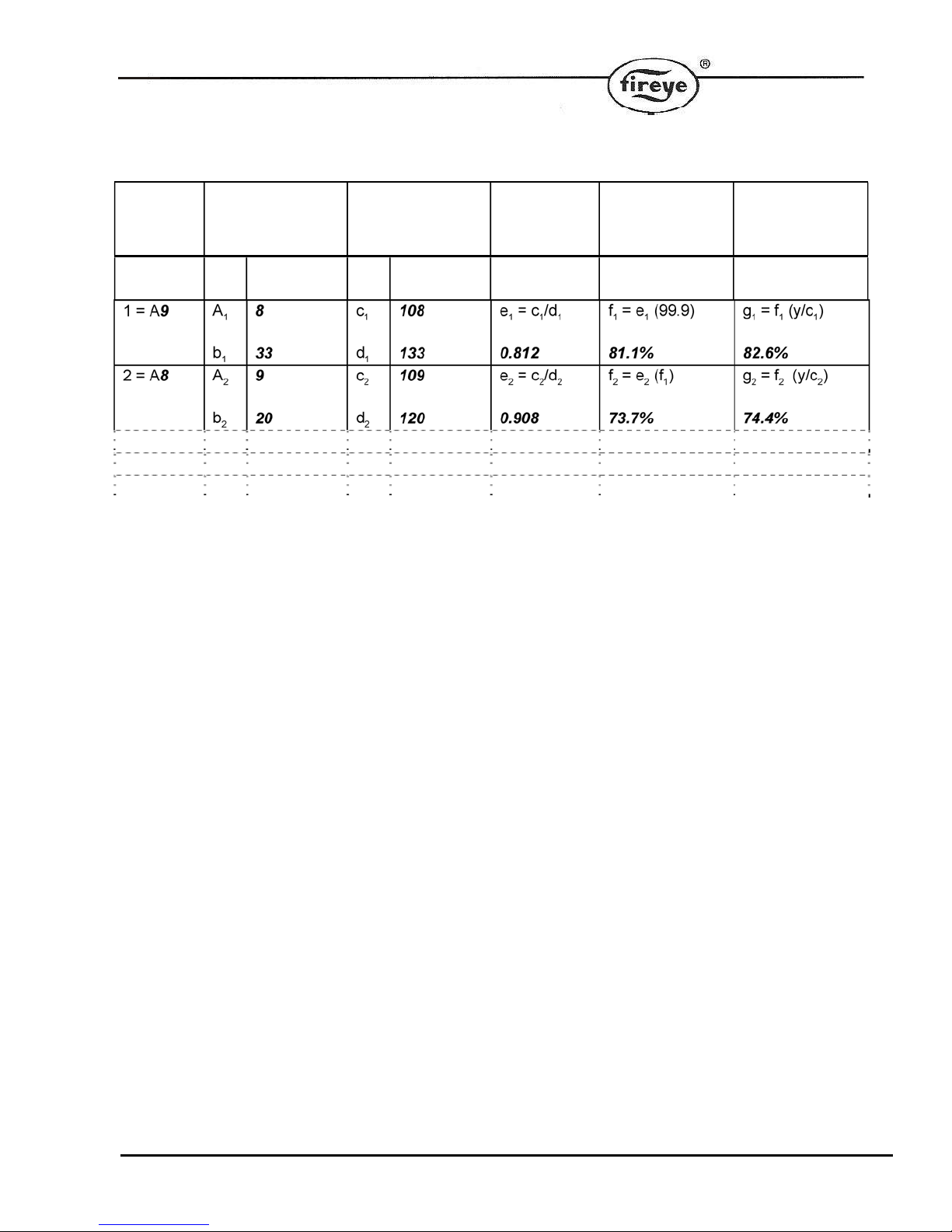
Example of table completed for A10 (high fire) to A8. In practice, the table must be filled out down to A3 (low
fire).
Profile
position
High fire
= A10
Excess Air Ex. Air + 100
y = x + 100
c = a + 100
d = b + 100
X
10
y
110
Ratio Airflow Fuelflow
----------------
99.9% 99.9%
39
Page 40

Table: Flow calculation table
Profile
Excess Air
position
High fire
= A
1 = A a
2 = A a
3 = A a
4 = A a
5 = A a
6 = A a
7 = A a
8 = A a
9 = A a
10 = A a
11 = A a
12 = A a
13 = A a
14 = A a
15 = A a
16 = A a
17 = A a
18 = A a
19 = A a
20 = A a
x y
c
1
b
1
c
2
b
2
c
3
b
3
c
4
b
4
c
5
b
5
c
6
b
6
c
7
b
7
c
8
b
8
c
9
b
9
c
10
b
10
c
11
b
11
c
12
b
12
c
13
b
13
c
14
b
14
c
15
b
15
c
16
b
16
c
17
b
17
c
18
b
18
c
19
b
19
c
20
b
20
Ex. Air + 100
y = x + 100
c = a + 100
d = b + 100
e
1
d
1
e
2
d
2
e
3
d
3
e
4
d
4
e
5
d
5
e
6
d
6
e
7
d
7
e
8
d
8
e
9
d
9
e
10
d
10
e
11
d
11
e
12
d
12
e
13
d
13
e
14
d
14
e
15
d
15
e
16
d
16
e
17
d
17
e
18
d
18
e
19
d
19
E
20
d
20
1
2
3
4
5
6
7
8
9
10
11
12
13
14
15
16
17
18
19
20
Ratio Airflow Fuelflow
= c1/d
= c2/d
= c3/d
= c4/d
= c5/d
= c6/d
= c7/d
= c8/d
= c9/d
= c10/d
= c11/d
= c12/d
= c13/d
= c14/d
= c15/d
= c16/d
= c17/d
= c18/d
= c19/d
= c20/d
1
2
3
4
5
6
7
8
9
f1 = e1 (99.9) g1 = f1 (y/c1)
f2 = e2 (f1) g2 = f2 (y/c2)
f3 = e3 (f2) g3 = f3 (y/c3)
f4 = e4 (f3) g4 = f4 (y/c4)
f5 = e5 (f4) g5 = f5 (y/c5)
f6 = e6 (f5) g6 = f6 (y/c6)
f7 = e7(f6) g7 = f7 (y/c7)
f8 = e8 (f7) g8 = f8 (y/c8)
f9 = e9 (f8) g9 = f9 (y/c9)
10f10
11f11
12f12
13f13
14f14
15f15
16f16
17f17
18f18
19f19
20f20
= e10 (f9) g10 = f10 (y/c10)
= e11 (f10) g11 = f11 (y/c11)
= e12 (f11) g12 = f12 (y/c12)
= e13 (f12) g13 = f13 (y/c13)
= e14 (f13) g14 = f14 (y/c14)
= e15 (f14)15 g15 = f15 (y/c15)
= e16 (f15) g16 = f16 (y/c16)
= e17 (f16) g17 = f17 (y/c17)
= e18 (f17) g18 = f18 (y/c18)
= e19 (f18) g19 = f19 (y/c19)
= e20 (f19) g20 = f20 (y/c20)
40
Page 41

Option 35.0 – Inlet temperature sensor serial number LV3
O 2
Each CANbus device connected to the system has a unique serial number allocated to it during production
testing. This number cannot be changed and is used to uniquely identify each device.
When the system is in commissioning mode the serial number of all the connected devices is read by the main
unit and displayed as a ‘list’ to allow the selection of the relevant serial number unit to be made.
Scrolling the list in an upward direction will scroll through all temperature sensor options available until ‘0,
nothing’ is displayed. Enter this value to disconnect the specified device from any hardware.
Scrolling the list in a downward direction will stop when the currently selected item is displayed, and the value
will stop flashing.
The display will show type information for each device present (such as ‘air temp’), but the commissioning
engineer should be aware of which serial number device is being used for which function.
O 2
Options 35.1 to 35.4-Hydrocarbon ratios of each fuel respectively (0.00 – 9.99) LV3
If a display of calculated burner efficiency, or ‘automatic trim commissioning’ is required, the hydrocarbon
ratios for the required fuels must be entered. These may be set between 0.0 and 9.99 inclusive, where the
value entered is the hydrocarbon ratio x 10. For example, for a hydrocarbon ratio of 0.157, a value of 1.57
should be entered.
Note : When firing multiple fuels, the mixture between the fuels fired may vary across the firing range of the
burner. When this happens, the effective hydrocarbon ratio and calorific value of the fuel combination will
change. The accuracy of the calculated efficiency and the ‘automatic trim commissioning’ procedure will be
adversely affected by this. It maybe that these functions should not be used, in which case these values
should be entered as zero.
O 2
Options 35.5 to 35.8-Calorific values of fuels/profiles 1 to 4 respectively (0.0 – 99.9) LV3
These option parameters are only available if option 35.0 (inlet temperature sensor) is not set to zero.
If a display of calculated burner efficiency is required, the calorific value of the required fuels must be entered.
-1
May be set between 0.0 and 99.9 MJkg
inclusive.
Note : When firing multiple fuels, the mixture between the fuels fired may vary across the firing range of the
burner. When this happens, the effective hydrocarbon ratio and calorific value of the fuel combination will
change. The accuracy of the calculated efficiency and the ‘automatic trim commissioning’ procedure will be
adversely affected by this. It maybe that these functions should not be used, in which case these values
should be entered as zero.
The table below shows the calorific values and hydrocarbon ratios of several common fuels. These values
should be used as a guide only. If the display is required to show gross efficiency in addition to entering the
gross calorific values a non zero value for the boiler radiated heat loss MUST be entered.
41
Page 42
Fuel Gross calorific value Net calorific value Hydrocarbon ratio
(x10)
Gas 52.8 47.6 3.20
Light oil 45.6 42.8 1.57
Medium oil 43.1 40.8 1.35
Heavy oil 42.9 40.5 1.28
O 2
Option 35.9 - Boiler radiated heat loss (0.0 – 9.9%) LV3
This option parameter is only available if option 35.0 (inlet temperature sensor) is not set to zero.
If this option parameter is set to zero the unit will calculate the net efficiency, if non-zero it will calculate gross
efficiency.
For accurate calculation of boiler gross efficiency, this option parameter must be set to the value of the heat
lost through the shell of the boiler at high fire as a percentage of the burner's output at high fire. The range of
this parameter is 0.0 to 9.9%.
O 2
Option 36.0 - Flue temperature alarm select (0/1) LV3
This option parameter is only available if option 30.0 is non zero.
If option 36.0 is set to 0, the flue temperature high and low alarms are disabled.
If option 36.0 is set to 1, the flue temperature high and low alarms are enabled and option parameters 36.1 to
36.4 and 37.1 to 37.4 become available.
O 2
Options 36.1 to 36.4 - Flue temperature low alarm values (0 – 999) LV3
Using option parameters 36.1 to 36.4, it is possible to set a different flue temperature low alarm value for each
profile combination. Each option parameter may be set to any value between 0 and 999 inclusive. The
temperature units should be set with respect to option parameter 30.4 .
If the burner is firing, it is only possible to make an adjustment to the option parameter that relates to the
selected profile. If the burner is not firing, the low alarm value for any profile selection may be adjusted.
When the flue temperature drops below the low alarm value for the selected profile, a fault number will appear.
O 2
Options 37.1 to 37.4 - Flue temperature high alarm values (0 – 999) LV3
Using option parameters 37.1 to 37.4, it is possible to set a different flue temperature high alarm value for
each profile selection. Each option parameter may be set to any value between 0 and 999 inclusive. The
temperature units should be set with respect to option parameter 30.4 .
If the burner is firing, it is only possible to make an adjustment to the option parameter that relates to the
selected profile. If the burner is not firing, the high alarm value for any profile selection may be adjusted.
When the flue temperature rises above the high alarm value for the selected profile combination, a fault
number will appear.
42
Page 43
O 2
Option 38.0 - Oxygen alarm select (0 – 2) LV3
Option parameter 38.0 is only available when option 30.5 (oxygen input select) is not set to zero and the
optional oxygen probe interface unit is connected.
Since the oxygen alarm values relate to the oxygen setpoint values, oxygen setpoint values must first be
entered in adjust ratio mode.
Option parameter
Meaning
38.0 value
0
1
Alarms disabled. Oxygen low and high alarms are disabled.
Alarms enabled, no non-volatile lockout. Oxygen low and high alarms are
enabled and option parameters 38.1 to 41.4 will become available. If an alarm
value is exceeded, a fault number will appear but no non-volatile lockout will
occur.
2
Alarms enabled with non-volatile lockout. Oxygen low and high alarms are
enabled and option parameters 38.1 to 41.4 will become available. If an alarm
value is exceeded, a fault number will appear and a non-volatile lockout will
occur.
O 2
O 2
O 2
O 2
Options 38.1 to 38.4 - Oxygen low alarm values at low fire (0.0 – 99.9%) LV3
Options 39.1 to 39.4 - Oxygen low alarm values at high fire (0.0 – 99.9%) LV3
Options 40.1 to 40.4 - Oxygen high alarm values at low fire (0.0 – 99.9%) LV3
Options 41.1 to 41.4 - Oxygen high alarm values at high fire (0.0 – 99.9%) LV3
Using option parameters 38.1 to 41.4, it is possible to set different oxygen alarm values at high fire and low fire
for each profile.
At firing positions other than high and low fire, the alarm limit is interpolated between the two points. For
example, if the oxygen limit has been entered as 5% of setpoint at low fire and 10% of setpoint at high fire, the
limit at mid fire will be 7.5%.
The alarm limits may set to any value between 0.0 and 99.9%, where the value entered relates to a
percentage deviation from each oxygen setpoint in the firing range.
If the burner is firing, it is only possible to make an adjustment to the option parameters that relate to the
selected profile. If the burner is not firing, the alarm values for any profile selection may be adjusted.
An oxygen low alarm will be caused by one or more of the following events :
The level drops below 0.5% O
The level drops below the low alarm limit for 2 minutes
The level drops below twice the low alarm limit for 30 seconds
An oxygen high alarm will be caused by one or more of the following events:
The level rises above the high alarm limit for 2 minutes
The level rises above twice the high alarm limit for 30 seconds
43
for 30 seconds
2
Page 44
When 2 probes the low alarm will also be caused by the following event:
The difference between the oxygen values exceeds the value set in option parameter 42.4 for 2 minutes
O 2
Option 42.0 – Second Oxygen probe interface serial number LV3
Each CANbus device connected to the system has a unique serial number allocated to it during production
testing. This number cannot be changed and is used to uniquely identify each device.
When the system is in commissioning mode the serial number of all the connected devices is read by the main
unit and displayed as a ‘list’ to allow the selection of the relevant serial number unit to be made.
Scrolling the list in an upward direction will scroll through all oxygen probe interface options available until ‘0,
nothing’ is displayed. Enter this value to disconnect the specified device from any hardware.
The FIREYE oxygen probe and associated electronics are not fail-safe. It is for this reason that the maximum
amount of oxygen trim allowed must be limited by the commissioning engineer using option parameter 32.1 to
32.4 . The trim must be limited to ensure that in the event of a probe fault (incorrect O
level), the combustion
2
does not become unsafe.
For applications demanding large amounts of oxygen trim to be applied, or where oxygen monitoring is
especially critical, a second oxygen probe and controller can be selected here. The two oxygen readings from
the probes can be compared when the burner is running to provide fail-safe oxygen monitoring.
O 2
Option 42.1 – Second Oxygen probe calibration offset value (0 – 999) LV3
This option parameter is only available if option 31.0 is non-zero.
This option parameter must be set to the calibration offset value that is specified with the probe supplied.
O 2
Option 42.2 – Second Oxygen probe calibration gain value (0 – 999) LV3
This option parameter is only available if option 31.0 is non-zero.
This option parameter must be set to the calibration gain value that is specified with the probe supplied.
44
Page 45
O 2
Option 42.3 – Second Oxygen probe calibrate enable (0 – 2) LV3
This option parameter is only available if option 31.0 is non-zero.
This option parameter must be used when calibrating the second FIREYE oxygen probe. There are three
possible values.
Option parameter
Meaning
31.3 value
0
No calibrate. This is the normal operating condition, where the probe is used to
measure the oxygen concentration in the flue.
1
Calibrate in air. The probe will be calibrated for 'offset' at the normal
atmospheric oxygen concentration.
2
Calibrate in reference gas. The probe will be calibrated for 'gain' in a reference
gas with a nominal oxygen concentration the level specified in option parameter
30.3 (typically 3.0%).
Once this calibration has been successfully completed the values in 31.1 and 31.2 will be automatically
updated.
O 2
Option 42.4 –Oxygen variation probe 1 to probe 2 LV3
This option parameter is only available if option 31.0 is non-zero.
This option parameter sets the maximum deviation between the oxygen values measured by the 2 separate
probes before a safety shutdown occurs. The probes are checked when the burner is firing only, and the time
to shutdown is 30 seconds. User intervention (i.e. fault mute) is required to restart the burner.
Option 44.0 - Set real time clock (0/1) LV1
Setting this option 1 enables the user to set the clock in the control used for fault logging. First set this option
to 1 then adjust the options 49.1 to 49.6. When these are correct, check that this option is still at 1, then press
the RUN key then the ENTER key.
Option 44.1 – Set Year (00 – 99) LV1
Option 44.2 – Set Month (1 – 12) LV1
Option 44.3 – Set Day (1 – 31) LV1
Option 44.4 – Set Hours (0 - 23) LV1
Option 44.5 – Set Minutes (0 - 59) LV1
Option 44.9 – Reset Fault Log (0 - 1) LV3
This option clears the current the fault history.
Set the option parameter to 1, then press RUN, then ENTER. The control will erase the fault history and return
to run mode.
45
Page 46

Option 45.0 - Erase / Restore enable (0 - 1) LV3
CAUTION
If this value is displayed as a ‘2’, the option parameter data has been ‘up-
loaded’ into the control, ensure all option parameters are set to match the
requirements of the burner to which it is connected. Failure to do so could
cause a hazardous condition to occur.
After all option parameters have been checked to match the requirements of the
burner to which it is connected, reset this option parameter to zero to allow the
system to operate.
If an attempt is made to operate the system with this option parameter set to ‘2’
a fault will be generated and the control will perform a non-volatile lockout,
preventing the burner from firing.
In order to erase information in memory for a specific profile selection (see option parameter 45.1), this option
must be set to '1'. Once the control has left set-up mode, this parameter will automatically be reset to '0'.
In order to restore information to the control from the back-up held in the display (see option parameter 45.2),
this option must be set to a ‘1’. Once the control has left set-up mode, this parameter will automatically be
reset to ‘0’.
If this option parameter is set to ‘2’ see caution message above.
Option 45.1 - Erase command (0 - 5) LV3
When erase enable (option 45.0) is set to '1', this option parameter determines which information will be
erased when the control leaves option set mode.
0 - No erase.
1 - Erase profile 1.
2 - Erase profile 2.
3 - Erase profile 3.
4 - Erase profile 4.
5 - Erase all setpoints and initialize all option parameters.
If 5 is selected, all profile setpoints will be erased and all option parameters will be set to default values.
The control will be initialized to the same state as when it was shipped.
Option 45.2 - Restore command (0 - 999) LV3
When erase / restore enable (option 45.0) is set to '1', this option parameter allows the back-up data held in
the display to be loaded into the main unit, this may take up to 5 minutes to complete during which time the
control will not allow the burner to operate.
To restore the data from the back-up held in the display set this option parameter to ‘100’.
If 100 is selected, the data from the back-up data held in the display will be loaded into the main unit.
A back-up of the data held in the main unit is automatically stored in the display when the control is in
modulation status.
46
Page 47

1.5 Commission ratio mode
1.5.1 Description
Commission ratio mode is used for entering a new profile or changing an existing profile.
Using commission ratio mode, it is possible to step through each setpoint including close, purge and ignition.
Once a setpoint has been entered, it is not possible to go back and modify it again in the same commissioning
session. To do this, adjust ratio mode must be used after all the required setpoints have been entered.
1.5.2 Using commission ratio mode
CAUTION
Use extreme care while commissioning the system. While operating in commissioning mode
the safety of the system is the sole responsibility of the commissioning engineer.
Incorrect positioning of either fuel or air could cause a hazardous situation to occur.
If the servo-motor positions have been up-loaded it is essential that the combustion is
verified at each firing position to ensure a hazardous condition cannot occur, and for the data
to be stored in the control.
To adjust the position of a servo motor or inverter, select the motor using the scroll keys, then use the
UP/DOWN keys to change the value.
Each setpoint in the profile is referred to with a letter and number (refer to the table below).
No. Name Comments
P0 Close This defines the positions the motors will move to when the burner is
off, and must be set to the lowest position each motor can reach.
P1 Purge This defines the positions the motor will move to when the burner is
purging, and can be set as required for each servo-motor.
P2 Ignition Position during ignition. May be outside the normal firing range.
P3 Low fire Low fire setpoint.
............. ...........
Px High fire High fire setpoint, which is the last setpoint entered (max. P24)
47
Page 48

The procedure for entering or modifying a profile is as follows: Please see Appendix, Section 2.3 for
suggestions on developing a profile.
1. Enter commission ratio mode (see section 1.3.1). P0 (close) is displayed.
2. If the close setpoint has been entered before and no change is required, press NEXT. Otherwise, move
each motor to its lowest position and press ENTER. P1 (purge) is displayed (flashing).
3. The controlled shutdown relay should now close (if there are no faults, and there is a call for heat – see
engineers key 18). The burner controller should now apply power to the profile select input for the required
profile (PE9 to PE12). If the purge position has been set before the selected motors will automatically
move to their relevant P1 positions and stop, if no change is required press NEXT. Otherwise, move each
motor to its required pre-purge position and press ENTER. If the purge setpoint has not been entered
before move each motor to its required position and press ENTER. P1 (purge) is displayed. Please note
that if a purge position for a particular drive has not been entered before the drive will remain at its closed
position. The engineer must ensure that the main combustion air damper is set to open enough to
purge the boiler.
4. Once P1 (purge) has been confirmed by pressing ENTER the unit will give a purge prove output. The unit
will remain at the pre-purge position until it receives the request from the burner controller to move to the
ignition position. If the ignition setpoint has been entered before, the drives will move to their ignition
positions and once all drives stop moving P2 (ignition) will be displayed, if a change is required or the
ignition setpoint has not been entered before, move all the motors being used to their required ignition
positions and press ENTER.
5. To attempt ignition of the burner, hold down the NEXT key for approximately three seconds, this
will give an ignition prove output to the burner controller. If it is wished to change the ignition position
adjust the relevant drive(s) and press ENTER, if the position is acceptable press NEXT. Once the unit
receives the request to modulate from the burner controller P3 will be displayed.
6. If the low fire setpoint has been entered before and no change is required, press NEXT. Otherwise, move
each drive to the required low fire position and press ENTER. P4 (next profile setpoint above low fire) is
displayed.
7. Repeat step 6 for each required profile setpoint, up to a minimum of P4 and a maximum of P23.
8. Leave commission ratio mode. The last profile setpoint entered will become the high fire setpoint.
If a controlled shutdown occurs, the control will return to step 2. The setpoints entered in the current
commissioning session are not lost and the NEXT key may be used to step through the start-up
sequence and fire the burner.
If a non-volatile lockout occurs, the setpoints are kept in the same way as for a controlled shutdown. It
will be necessary to remove all faults before moving further than step 2.
If power is removed from the controller the setpoints entered in the current commissioning session will
be lost.
1.5.3 Leaving commission ratio mode
Commission ratio mode
ENTERRUN
Run mode
To leave commission ratio mode and return to run mode, press the key labeled RUN followed by the key
labeled ENTER.
.
48
Page 49

If P3 (or higher) has been commissioned, the existing profile will be overwritten. If you do not wish
pp
the existing profile to be overwritten, disconnect the power to the control without pressing RUN and
ENTER.
Only the setpoints used in the current commissioning session will be stored. For example, if an
existing profile has setpoints up to P15 but only the setpoints up to P10 were viewed or altered, then only
the setpoints up to P10 will be stored. Therefore, it is vital that NEXT is pressed to get to the last setpoint
in the profile before leaving commission ratio mode. This does not apply if only the close, purge or ignition
setpoints (P0, P1 or P2) are altered.
1.6 Adjust ratio mode
1.6.1 Description
Adjust ratio mode is used only for changing an existing profile.
Using adjust ratio mode, it is possible to modify the motor positions for any setpoint in the firing range from
low to high fire (P3 and higher).
It is also possible to view all setpoints (P0 and higher), even with the burner off.
The setpoints may be chosen in any order.
It is not possible to modify any motor position so that it is higher than the high fire setpoint.
It is not possible to modify the close, purge or ignition positions (P0, P1 or P2 respectively). For this,
commission ratio mode must be used.
1.6.2 Entering adjust ratio mode
Run mode, burner on
COM
Su
lierpasscode
ENTER
To enter adjust ratio mode, turn the burner on. Once the burner begun its startup sequence, press the key
labeled COM and obtain the adjust ratio passcode value using the UP/DOWN keys. Once the correct
passcode value has been obtained, press the key labeled ENTER.
If the entered passcode was correct, ‘A n’ will be seen on the display, where n is the number of the setpoint
currently under adjustment.
49
Page 50

1.6.3 Using adjust ratio mode
CAUTION
Use extreme care while commissioning the system. While operating in adjust
ratio mode the safety of the system is the sole responsibility of the
commissioning engineer.
Incorrect positioning of any drive could cause a hazardous situation to occur.
To adjust the position of a servo-motor or inverter, select the relevant drive and use the UP/DOWN keys.
To change the setpoint being modified, using the scroll key select the setpoint and then use the UP/DOWN
keys.
Each setpoint in the profile is referred to with a letter and number.
No. Name Comments
A0
A1
A2
A3
............. .................
Ax High fire High fire setpoint, which was the last setpoint entered (max P24)
The procedure for modifying a setpoint is as follows :
1. Enter adjust ratio mode. ‘A n’ is displayed in the window, where n is the number of the setpoint that is
closest to the current firing position.
2. Use the scroll key to select the setpoint and use the UP/DOWN keys to move to the setpoint in the firing
range to be altered.
3. Wait for the ‘A n’ display to stop flashing and modify the drive(s) as required.
4. If the modified positions are not required, press the NEXT key to return the drive(s) to their original
positions or use the scroll key to move to a different setpoint.
5. Press the ENTER key to store the new drive positions for the current setpoint.
6. Repeat steps 2-5 as required. Each time step 5 is completed, the new positions will be stored
permanently.
7. Leave adjust ratio mode.
Close
Purge
Ignition
Low fire
The close setpoint cannot be altered in adjust ratio mode.
The purge setpoint cannot be altered in adjust ratio mode.
The ignition setpoint cannot be altered in adjust ratio mode.
Low fire setpoint.
If the ‘A n’ display is flashing, it will not be possible to adjust the position of any of the drives. This may be for
one of the following reasons :
The burner is not firing. Switch the burner on and wait for the control to begin modulating.
The current setpoint is A0, A1 or A2. Use commission ratio mode to adjust these setpoints.
50
Page 51

The drive(s) are moving to the required positions. Wait for the drive(s) to stop moving.
1.6.4 Leaving adjust ratio mode
Adjust ratio mode
RUN
ENTER
Run mode
To leave adjust ratio mode and return to run mode, press the key labeled RUN followed by the key labeled
ENTER.
1.7 Interrogating the software issue
There are two methods for finding the software issue :
1. From run mode, press the COM key.
2. Use the engineer’s key. Refer to Fireye bulletin PPC-6001 section 6.6 for details.
51
Page 52
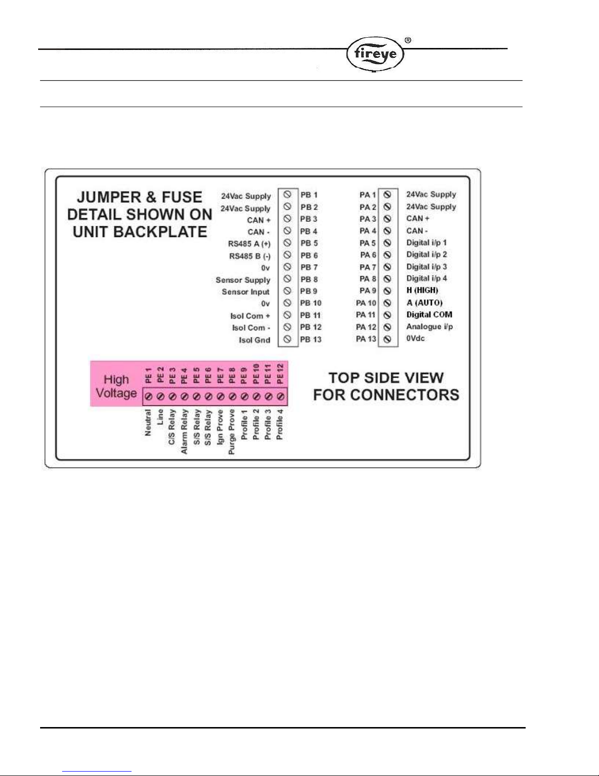
2 Appendix
2.1 Terminal Designation
Note: All wiring to terminals “PA & PB” are low voltage and
must be braided shielded wire per table 2.6.1A of Fireye Bulletin
PPC-6001. Wiring to terminals “PE” are line voltage. The
maximum wire size is 16AWG (19.3mm) for all terminals.
52
Page 53
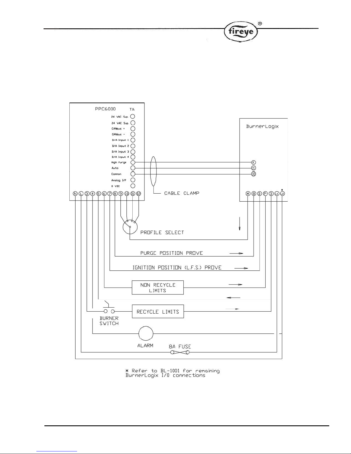
2.2 Typical Wiring Diagram / BurnerLogix
53
Page 54
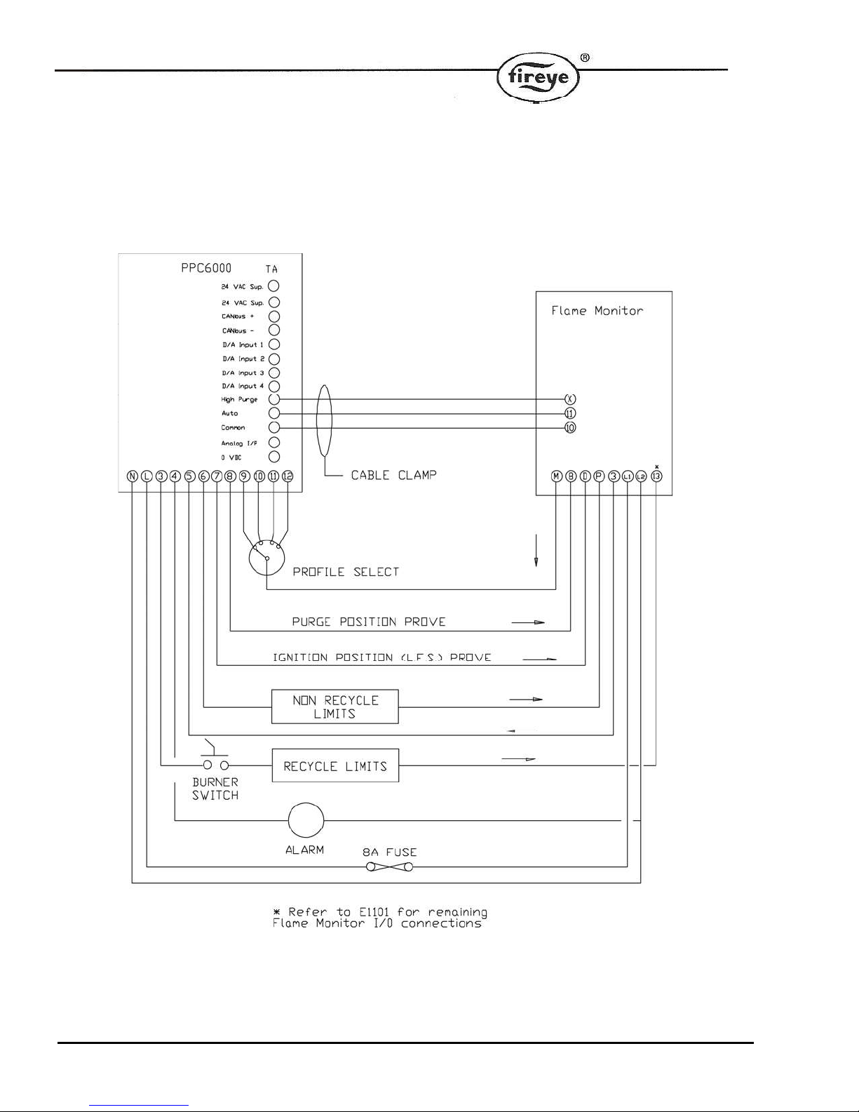
Typical Wiring Diagram / E110 Flame Monitor
54
Page 55

2.3 Combustion Profile Setup Guideline
It is safe to say that most burners do not have fuel and air control devices that have linear flow characteristics.
When commissioning the Fireye Nexus/PPC parallel positioning system, the following procedure will help
assure the maximum benefit will be realized. Before starting the installation, the commissioning engineer
should try to verify the maximum combustion air damper (flow) position so as to know the “target” high fire
position. This can be done by rotating the original jack shaft before it is removed and measuring the air
damper opening. If possible, it should be marked for reference.
There are 24 points available for creating a profile, P0 (closed/off) to P23 (high fire). The first three positions,
P0, P1&P2 are required to reach ignition which may or may not be the same as low fire (P3). After establishing
a good low fire and entering the values at P3, the display will now indicate P4 with the drives at the P3
position. At this time the main air drive or drives should be increased a minimum of one degree or until the
observed oxygen level increases approximately 1.0 to 2%, do not press enter at this time. At this point the
fuel drive should be increased slowly to bring the oxygen level back down to the desired level and entered at
this time. Following this procedure from low to high fire will yield a relatively linear profile. That is to say, each
position will increase the fuel and air flows by nearly equal amounts from low to high fire, thus making the
profile somewhat linear. This will aid in setting up O2 trim.
The PPC6000’s Engineers Key 44 (see section 6.6) displays the actual O2 value of the Fireye oxygen probe
when fitted. It should be noted that the reading of the Fireye probe will be between 1 and 1.5% lower than
most portable combustion analyzers. This is normal and due to the difference between wet and dry samples.
Bear in mind the PPC6000 will trim to the value of the Fireye probe, not to the value of a portable analyzer.
For example:
Position
Air Drive Fuel Drive Observed O2% Increased O2%
P3 5.0 15.0 7.0 9.0
P4 7.5 18.0 7.0 9.0
P5 12.0 22.0 6.0 8.0
P6 17.0 28.0 5.0 7.0
P7 24.0 33.0 4.0 6.0
P8 29.0 38.0 4.0 6.0
P9 35.0 45.0 4.0 6.0
P10 43.0 55.0 3.5 5.0
P11 53.0 67.0 3.5 5.5
P12 66.0 79.0 3.5 5.0
P13 80.0 88.0 3.5 High Fire
NOTE: The angular change in the air drive position required to achieve the 1.0 to 2.0% increase in observed
oxygen level may increase as the burner fires at higher rates. This is normal as the air “damper” will not likely
be linear. When approaching high fire large increases in the air drive servomotor travel may be required to
increase the oxygen reading by 1.0 to 2.0%. As a rule, this should be avoided as the burner is potentially “out
of air” and in so doing, the effective input to the boiler will be negligible. This would also affect the operation of
oxygen trim should this option be used.
55
Page 56

56
Page 57

This manual may be downloaded from the Fireye web site at:
y
www.Fireye.com
NOTICE
, Click on “Bulletins” or search by bulletin
number.
WARRANTIES
When Fireye products are combined with equipment manufactured by other and/or integrated
into systems designed or manufactured by others, the Fireye warranty, as stated in its General
Terms and Conditions of Sale, pertains only to the Fireye products and not to any other
equipment or to the combined system or its overall performance.
FIREYE guarantees for one year from the date of installation or 18 months from date of
manufacture of its products to replace, or, at its option, to repair any product or part thereof
(except lamps and photocells) which is found defective in material or workmanship or which
otherwise fails to conform to the description of the product on the face of its sales order. THE
FOREGOING IS IN LIEU OF ALL OTHER WARRANTIES AND FIREYE MAKES NO
WARRANTY OF MERCHANTABILITY OR ANY OTHER WARRANTY, EXPRESS OR
IMPLIED. Except as specifically stated in these general terms and conditions of sale, remedies
with respect to any product or part number manufactured or sold by Fireye shall be limited
exclusively to the right to replacement or repair as above provided. In no event shall Fireye be
liable for consequential or special damages of any nature that may arise in connection with such
product or part.
NXPG-6001
FIREYE
3 Manchester Road
Derry, New Hampshire 03038 USA
www.fire
e.com
Supersedes May 10, 2007
APRIL 8 2013
57
 Loading...