

Page 1
November 7, 2019
M-4001
FIREYE
DESCRIPTION
M4RT24
Low Voltage
FLAME SAFEGUARD CONTROLS
WARNING: Selection of this control for a particular application should be made by a competent
professional, licensed by a state or other government agency. Inappropriate application of this
product could result in an unsafe condition hazardous to life and property.
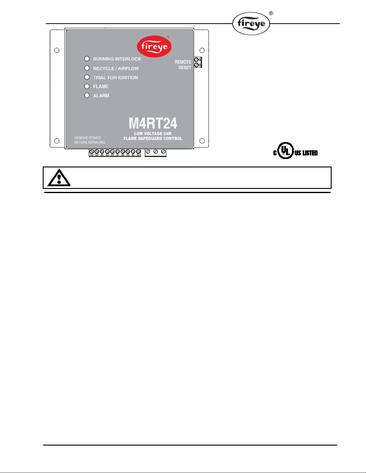
The Fireye® M4RT24 Flame Safeguard Control is a compact burner management system for low
voltage (24V AC/DC) applications. It is designed to provide automatic ignition and flame monitoring
for commercial sizes for heating and process burners that use gaseous or liquid fuels. Flame
monitoring is accomplished by an Ultra-Violet (UV) detector or Flame Rod (FR), with the built in
amplifier and programmer. Control functions and timings such as recycle/non-recycle, purge timing,
and pilot trial for ignition (PTFI) time are pre-configured at the factory, and are determined by part
number (e.g. M4RT24-17). Flame Failure Response Time (FFRT) is fixed at 4 seconds. LED
indicator lights indicate the operating status of the control.
In the event of ignition failure, following a safety shutdown, the unit locks out, activ ating an alarm
circuit. Available remote reset terminals can be used to reset the control from a lockout state. A
detailed description of the programmer sequence is found later in this document. Test jacks are
provided to permit flame signal strength measurement during operation.
The M4RT24 control incorporates a safety circuit that is operative on each start. If flame (real or
simulated), is detected prior to a start or during the purge, the fuel valves will not be energized, and
the unit will lockout. A proof of closure (POC) input could be used as an additional safety to
monitor the main fuel shutoff valves during burner startup.
All M4RT24 controls do not require a wiring base due to the available terminal blocks for easy connectivity. See INSTALLATION OF CONTROL, SCANNERS, AND FLAME DETECTORS (page
5) for temperature and wiring requirements.
1
Page 2
SPECIFICATIONS
Supply:
24V (DC or AC) (+10%, -15%)
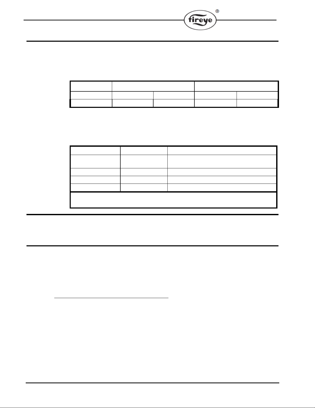
Table 1: AMBIENT TEMPERATURE LIMITS
M4RT24 Control +140°F +60°C - 40°F - 40°C
UV90L-2 Scanner +194°F +90°C - 40°F - 40°C
Power Consumption: 6 Watts (Operating)
Shipping Weight (Approx.): 2 lbs. (0.9kg)
Table 2: LOAD RATINGS
Fireye Terminal Typical Load Rating
P5.1, P5.3
P5.2 Main Fuel Valve 100VA
P5.5 Motor or contactor 4 F.L.A., 8 L.R.A.
P5.7 Alarm 25VA
APPROVALS
Underwriters Laboratories Inc.
File: MCCZ7.MP1537 and MCCZ.MP1537
ORDERING INFORMATION
MAXIMUM MINIMUM
Pilot valve
Ignition Transformer
Minimum load requirement = 100mA
F.L.A. = Full Load Amps; L.R.A. = Locked Rotor Amps
75VA
2
CONTROL:
M4RT24-17 Control, 24V (AC/DC), 5sec Purge, 5sec PTFI, recycle operation
M4RT24-33 Control, 24V (AC/DC), 5sec Purge, 10sec PTFI, Non-recycle operation, 4sec FFRT
M4RT24-35 Control, 24V (AC/DC), 35sec Purge, 10sec PTFI, Non-recycle operation, 4sec FFRT
NOTE: Please consult factory for other timing options.
FLAME DETECTORS:
UV90L-2 UV scanner, front and side (90
o
) lateral view, terminal block hook-up
69ND1-1000K4 Flame rod 1/2” NPT Mount, 12” Length
69ND1-1000K6 Flame rod 1/2” NPT Mount, 18” Length
69ND1-1000K8 Flame rod 1/2” NPT Mount, 24” Length
Page 3
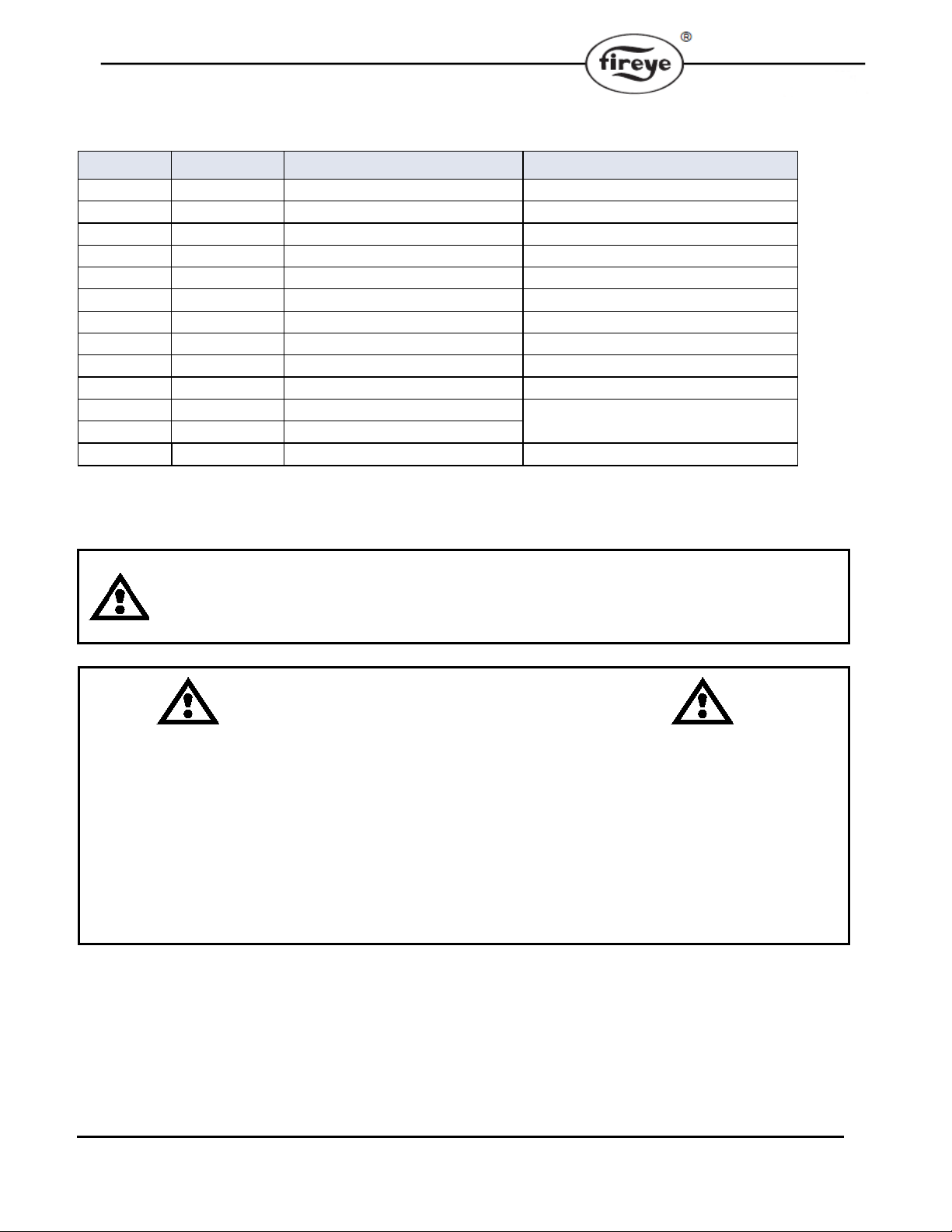
Table 3: TERMINAL WIRING
Terminal No. Type Description Rating
P5.1
P5.2
P5.3
P5.4
P5.5
P5.6
P5.7
P5.8
P5.9
P5.10
P6.1
P6.2
P6.3
Output Ignition 24V AC/DC, see load ratings
Output
Output
Input Recycle / Airflow
Output
Input Running/Safety Interlock 24V AC/DC, up to 15A
Output
Input
Input
Input
Input
Input
Input
Main Fuel Valve
Pilot Valve
Blower
Alarm
Proof of Closure (FVES)
24V Return
Earth Earth Ground
UV Scanner (-)
UV Scanner (+)
Flame Rod Flame Rod Excitation
24V AC/DC, see load ratings
24V AC/DC, see load ratings
24V AC/DC
24V AC/DC, see load ratings
24V AC/DC, see load ratings
24V AC/DC, 50mA
Power Supply Ground
UV Scanner Excitation
WARNING: Failure to properly install, operate, or commission the equipment in this manual could result
in significant property damage, severe injury, or death. It is the responsibility of the owner or user to
ensure that the equipment described is installed, operated and commissioned in compliance with this
manual and other system component manuals, as well with all applicable national and local codes.
!!!WARNING!!!
Boiler operation, maintenance, and troubleshooting shall only be conducted by trained personnel. Persons troubleshooting lockouts or resetting the control must respond properly to troubleshooting error codes as described in this
product bulletin.
Jumpers being used to perform static test on the system must only be used in a controlled manner and must be removed
prior to the operation of the control. Such tests may verify the external controllers, limits, interlocks, actuators, valves,
transformers, motors and other devices are operating properly. Such tests must be conducted with manual fuel valves in
the closed position only. Replace all limits and interlocks not operating properly, and do not bypass limits in interlocks.
Failure to follow these guidelines may result in an unsafe condition hazardous to life and property.
3
Page 4
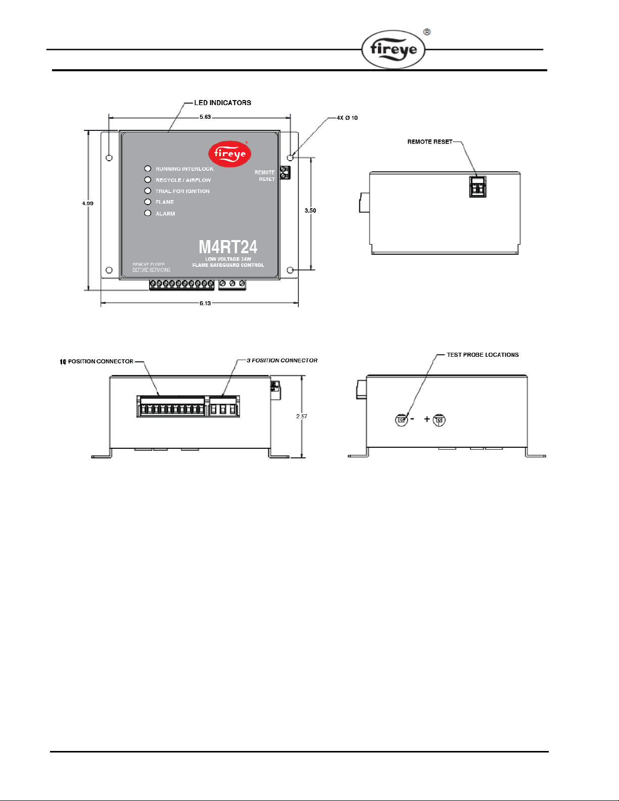
MECHANICALS
4
Page 5
p
INSTALLATION OF CONTROL, SCANNERS, AND FLAME DETECTORS
Mounting and wiring the control
Mount the control in an enclosure/burner panel that provides the proper protection for the control.
The location should be free from moisture, excessive vibration, and within the specified ambient
temperature rating. The control may be mounted in any angular position.
All wiring should comply with applicable electrical codes, regulations, and local ordinances. Use
moisture resistant wire suitable for at least 90
through 10. Consult the factory for assistance with non-standard applications.
WARNING: Installer must be trained and qualified. Follow the burner manufacturer's instructions, if supplied. Otherwise, proceed as follows.
WARNING: Controls require safety limits utilizing isolated mechanical contacts. Solid state
limit switches are not acceptable and should not be used due to their high leakage currents.
C. Circuit recommendations are foun d on pages 9
WARNING: Remove
ower from the control before proceeding.
Replaceable Fuse
The M4RT24 is designed with two field replaceable fuses. The fuses are located on the printed circuit board. The fuse(s) will blow as a result of an overload condition on Terminal P5.1, P5.2, P5.3 ,
P5.5 or P5.7. Fuse F1 protects P5.1 (Ignition), P5.2 (Main Fuel Valve), P5.3 (Pilo t Valve) and P5.7
(Alarm). Fuse F2 protects P5.5 (Blower). To replace the fuse, remove power from the system.
Unmount the control from the sub-plate. With the aid of a small screwdriver or similar tool, remove
the fuse from its holder. Install a Fireye replacement fuse (P/N 23-246) or equivalent fuse (e.g.
Littelfuse 37315300410, 6.3A, 125V).
WARNING: Turn off the power when installing or servicing the control.
5
Page 6
S
S
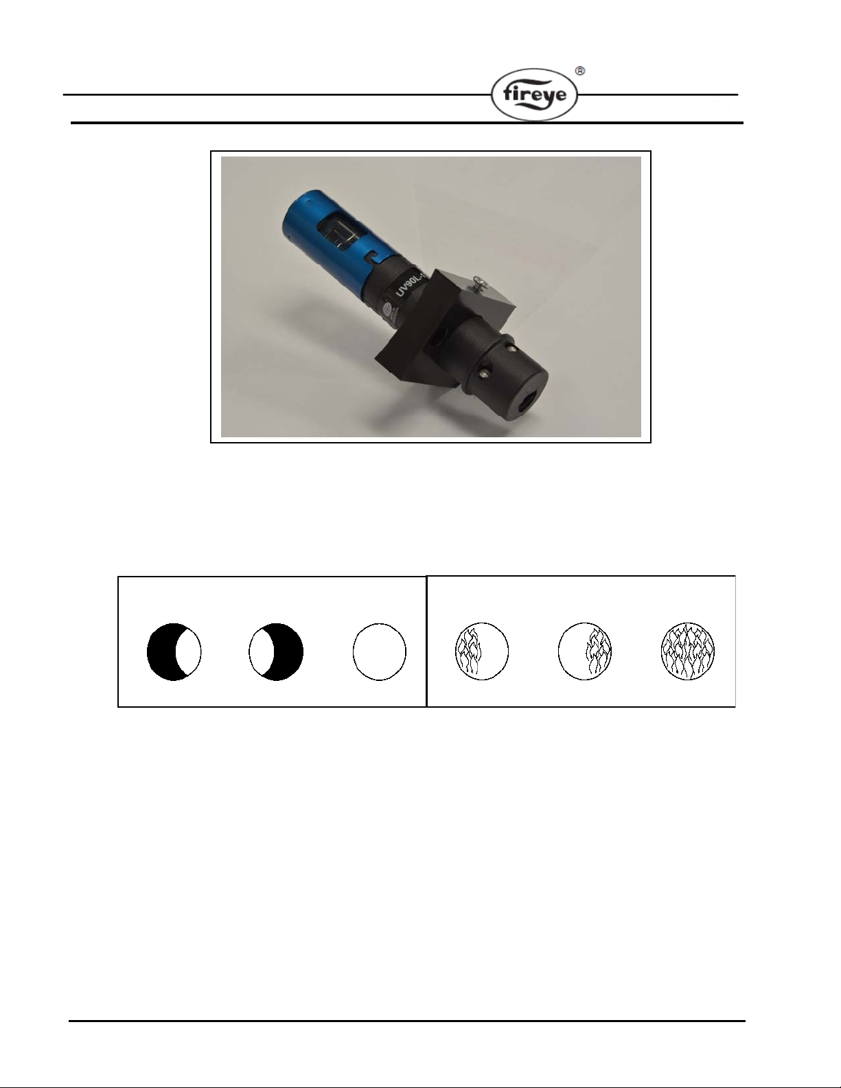
INSTALLATION - UV Scanners
INSTALLATION - UV SCANNERS
Where possible, obtain the burner manufacturer’s instructions for mounting the scanner. This information is available for most standard burners. The scanner mounting should comply with the
following general instructions:
1. Position the scanner within 39 inches (1 meter) of the flame to be monitored.
2. Select a scanner location that remains within the ambient temperature limits of the UV scanner.
UV90L-2
SCANNER MUST HAVE UNOBSTRUCTED
VIEW OF FLAME
NOT THIS NOT THIS BUT THI
3. If the scanner mounting pipe sights through the refractory, d o not extend it more than halfway
through. The sight pipe must permit an unobstructed view of the pilot and/or main flame, and
both pilot and main flames must completely cover the scanner field of view.
4. Smoke or unburned combustion gases absorb ultra-violet energy. On installations with negative
pressure combustion chambers, a small hole drilled in the sight pipe assists in keep ing the pipe
clean and free from smoke. For positive pressure furnaces, provide clean air to pressurize the
sight pipe, if necessary.
5. Two UV90L-2 scanners may be installed on the burner if it is necessary to view two areas to
obtain reliable detection of the flame. They must be wired in parallel.
6. Request the assistance of any Fireye field office for recommendations of a proper scanner
installation on a non-standard application.
FLAME MUST COMPLETELY COVER
SIGHT OPENING
NOT THIS NOT THIS BUT THI
6
Page 7
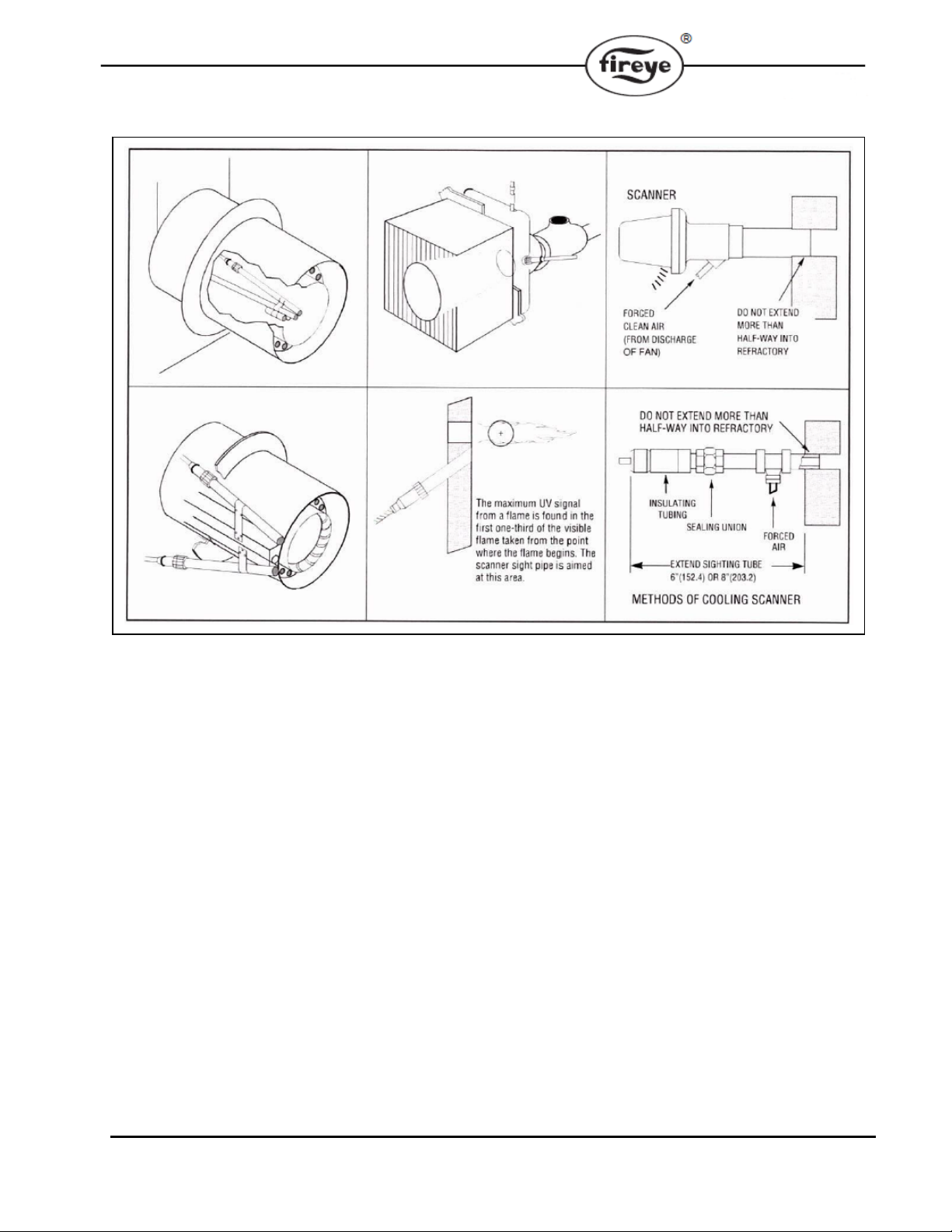
TYPICAL SCANNER INSTALLATIONS
WIRING - UV SCANNERS
The UV90L-2 is supplied with a terminal board. Use two #20 AWG conductors rated for 90° C,
600V to connect the UV90L-2 to the control.
There is polarity associated with the UV scanner wiring. Connect the “+” terminal to P6.2 and the “-”
terminal to P6.1. Scanner wires must be installed in a separate conduit. The wires from several
scanners may be installed in a common conduit.
1. Selection of Wire
a. Wiring: For extended scanner wiring up to 500 feet (152 M), and for shorter lengths to
reduce signal loss, use a shielded wire (Belden 8254-RG62 coaxial cable, or equal) for
each scanner wire. The ends of the shielding must be taped and not grounded.
b. Avoid asbestos insulated wire.
c. Multi-conductor cable is not recommended without prior factory approval.
2. High voltage ignition wiring must not be installed in the same conduit with flame detector
wires.
7
Page 8
INSTALLATION - 69ND1 FLAME ROD
The 69ND1 flame rod proves a gas pilot flame and/or main gas flame. It is a spark plug type unit
consisting of
a spark plug connector for making electrical connections. The 69ND1 is available in 12,
24
" lengths.
The flame rod may be located to monitor only the gas pilot flame or bo th the gas pilot and main gas
flames. It is mounted on a
1
/
" NPT mount, a KANTHAL flame rod, a glazed porcelain insulating rod holder and
2
" 18" or
1
/
" NPT coupling.
2
The following instructions should be observ ed:
1. Keep flame rod as short as possible.
1
/
2. Keep flame rod at least
" from any refractory.
2
3. Flame rod should enter the pilot flame from the side so as to safely prove an adequate pilo t
flame under all draft conditions.
4. If the flame is nonluminous (air and gas mixed before burning), the electrode tip should extend
at least
1
/
" into the flame, but not more than halfway through.
2
CORRECT
POSITION
OF ROD
INADEQUATE FLAME
CORRECT POSITION
OF PILOT FLAME
WRONG POSITION
OF ROD
PILOT BURNER
5. If the flame is partly luminous, the electrode tip should extend only to the edge of the flame. It
is not necessary to maintain absolutely uninterrupted contact with the flame.
6. It is preferable to angle the rod downward to minimize the effect of sagging and to prevent it
from coming in contact with any object.
7. An adequate grounding surface for the flame must be provided. The grounding surface in actual
contact with the flame must be at least four times greater than the area of the portion of the
flame rod in contact with the flame. It is essential to adjust the flame rod an d ground area ratio
to provide a minimum signal reading of 6.0 VDC.
Note: Interference from the ignition spark can alter the true signal reading by adding to, or
subtracting from it. This trend sometimes may be reversed by interchanging the primary wires (lin e
voltage) to the ignition transformer. This interference can also be reduced by the addition of
grounded shielding between the flame rod and ignition spark.
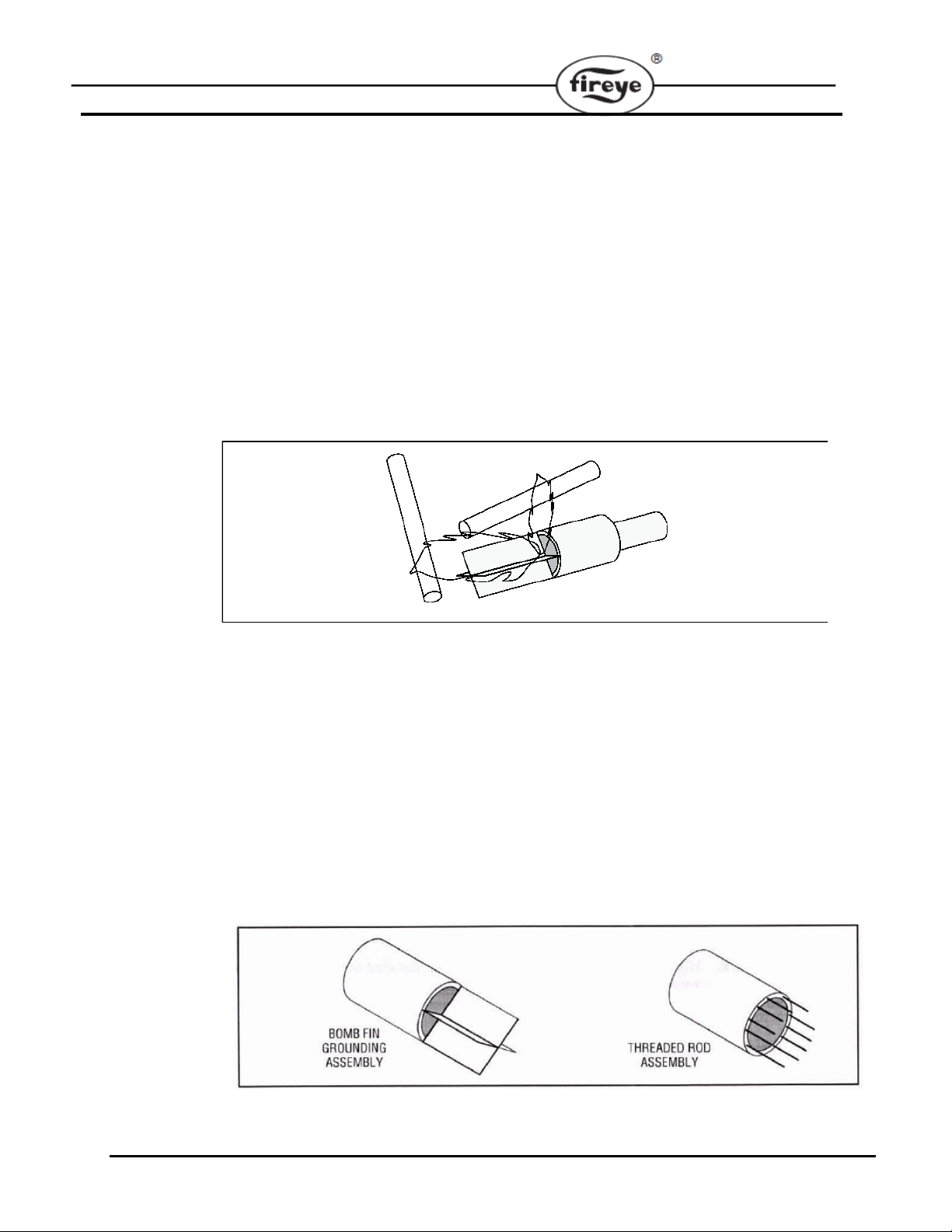
8. Proven types of flame grounding adap ters, as shown below, may be used to provide adequate
grounding surface. High temperature stainless steel should be used to minimize the effect of
metal oxidation. This assembly may be welded directly over the pilot or main burner nozzle.
8
Page 9
p
prop
WIRING OF FLAME RODS
For proper operation of flame rectification systems, it is necessary to maintain at least 20 megohms
insulating resistance in the flame rectification circuit.
1. The scanner should be wired using metal cable or rigid conduit.
2. High voltage wiring must not be installed in the same conduit with scanner wiring.
Selection of Scanner Wire
1. Use #18, 20, or 22 gauge wire with 90° C, 600 volt insulati o n fo r up to 20 f eet dist ance.
2. The type of insulation used with flame rectification is important, since it must protect against
current leakage resistance to ground. Use Belden 8254-RG62 Coaxial Cable (or equal) for runs
greater than 20 feet. Maximum wiring run not to exceed 100 feet.
MAINTENANCE
UV Scanner
The UV scanner should be periodically checked for faulty or runaway condition. With the system in
standby, manually shutoff the main fuel supply. Run the system and make sure that the control does
not detect a flame or the scanner is not “firing.”
RESET
69ND1 Flame Rod
The flame rod and its insulator should be kept clean by washing routinely with soap and water. Rods
should be routinely replaced as they oxidize.
Flame Signal Strength
Routine observation of the flame signal strength will forewarn any d eterioration in the capability of
the flame detector or its application.
Periodic Safety
It is recommended that a procedure be established to test t he complet e flam e safeguard system at least
once a month. This test should verify the proper operati on of all limit switches and safety interlocks as well as flame failure protection and fuel safety shutoff valve tightness.
In the event of a lockout condition, the M4RT24 can be reset v ia the remote reset terminals. Using
those terminals, a remote, dry contact pushbutton switch can be connected. The maximum wire
length is 100 feet (no.18 AWG wire size is recommended).
CAUTION: Remote reset is recommended only on a control solely for proved ignition programming (pilot ignited burner) or a control for use only with appliances in which
unburned fuel cannot accumulate and that is intended for installation in inaccessible
locations such as o
WARNING: When choosing a model of the M4RT24, selection of the Purge time and
Recycle / Non-Recycle operation for a particular application, should only be performed by
a competent professional, licensed by a state or other government agency. Inappropriate
selection of these safety critical parameters could result in an unsafe condition hazardous
to life and
en-flame, ceiling-suspended gas heaters.
erty.
9
Page 10

LED INDICATOR LIGHTS
The M4RT24 has 5 LED lights to indicate the operating status of the control. The function of these
lights are:
RUNNING INTERLOCK: This LED is activated whenever input Terminal P5.6 is energized and
after Terminal P5.8 has been energized. The burner system safety interlocks should be wired in
series and connected to the M4RT24 Terminal P5.6 (Running/Safety interlock).
RECYLE/AIRFLOW: This LED is lit whenever all of these conditions exist:
— Input Terminal P5.6 is energized (operating control and safety interlocks closed).
— Input Terminal P5.4 is energized (proof of airflow switch is closed).
— Output Terminal P5.5 is energized (blower motor).
TRIAL FOR IGNITION: This LED is activated only during the Pilot Trial for Ignition Period.
FLAME: This LED is activated whenever an adequate flame signal is detected between the
M4RT24 Terminals P6.1 & P6.2 (UV scanner) or P6.3 & Earth (Flame rod). It should be noted that
the LED is also activated whenever there is false flame condition.
ALARM: This LED is energized whenever a safety lockout occurs. (See APPLICATION AND
FUNCTION section).
NOTE: The M4RT24 is not powered until the user’s operating control is energized and both Terminals P5.6 and P5.8 are energized.
APPLICATION AND FUNCTION
The M4RT24 provides prepurge, ignition and flame safeguard for heating and process gas fired
burners. The “recycle” or “non-recycle” operation is configured at the factory. Purge times and trial
for ignition times are also set at the factory.
The M4RT24 amplifier circuitry is designed to utilize a UV Scanner or Flame Rod for flame detection. The Flame Failure Response Time (FFRT) is fixed at 4 seconds.
Pilot Ignited Burners - “Recycle” Operation
When configured for recycle, the typical wiring arrangement illustrated on page 15 for pilot ignited
burners provides the following function:
1. With power applied to Terminals P5.6 (Running Interlock) and P5.8 (Proof of Closure), the
burner motor circuit (Terminal P5.5) is energized. The control then waits for the proof of
airflow input (Terminal P5.4) to be energized
2. The Pre-purge timing starts when Terminal P5.4 is energized.
3. Following the prepurge period, KL-1 closes, energizing Terminal P5.3 which powers the pilot
gas valve and Terminal P5.1 which powers the spark ignition. A five or ten sec. (based on configuration) trial for ignition is initiated (
4. When pilot flame is detected (
powers the main fuel valve, KF-2 opens de-energizing Terminal P5.1 which shuts off the spark
ignition.
5. When the operating control opens its circuit, or if a power failure occurs, the entire system is
de-energized. Power interruptions in the millisecond range do not affect the operation of the
control. Power interruptions of longer duration will cause the control to recycle.
6. In the event the pilot flame is not detected by the end of trial for ignition period (TFI), the pilot
gas valve (Terminal P5.3) and spark ignition (Terminal P5.1) are de-energized. A safety shutdown occurs followed in approximately 30 seconds by a safety lockout that de-energizes the
blower motor (Terminal P5.5) and energizes the lockout alarm circuit (Alarm LED lit).
7. In the event of a flame failure during a firing period, the pilot and main fuel valves are de-ener-
gized. Following the prepurge period, with proven air flow (AirFlow LED lit), the pilot gas valve
and spark ignition are re-energized and a five or ten sec. (based on configuration) trial for
ignition is initiated (TFI LED lit). If pilot flame is detected (Flame LED lit), the main fuel valve
Trial for Ignition LED lit).
Flame LED lit), KF-1 closes, energizing Terminal P5.2 which
10
Page 11

is energized, the spark ignition is de-energized. In the event the pilot flame is not detected by
the end of trial for ignition period (TFI), the pilot gas valve (Terminal P5.3) and spark ignition
(Terminal P5.1) are de-energized. A safety shutdown occurs followed in approximately 30
seconds by a safety lockout that de-energizes the blower motor (Terminal P5.5) and energizes
the lockout alarm circuit (Alarm LED lit).
8. Remote Reset is required following any safety lockout.
NOTE: Wait 10 seconds after lockout before restarting the control.
Pilot Ignited Burners - “Non-recycle” Operation
The function of “non-recycle” pilot ignited burners is the same as described for the “recycle” controls, except that the “non-recycle” operation will lockout following any flame failure. “Recycle” or
“non-recycle” operation is configured at the factory.
Direct Spark Ignited Burners - “Recycle” Operation
The typical wiring arrangement illustrated on pages 15 for direct spark ignited burners provides the
following functions:
1. With power applied to Terminal P5.6 (Running Interlock) and Terminal P5.8 (Proof of
Closure), the burner motor circuit (Terminal P5.5) is energized. The control then waits for the
proof of airflow input (Terminal P5.4) to be energized.
2. The Pre-Purge timing starts when Terminal P5.4 is energized.
3. Following the selected prepurge period, KL-1 closes, energizing Terminal P5.3 which powers
the primary main fuel valve, and Terminal P5.1 which powers the spark ig nition. A five or ten
second (based on factory configuration) trial for ignition is initiated (TFI LED lit).
4. When pilot flame is detected (Flame LED lit), KF-1 closes, energizing Terminal P5.2 which
powers the secondary main fuel valve, and KF-2 opens, de-energizing Terminal P5.1 which
shuts off the spark ignition.
5. When the operating control opens its circuit, or if a power failure occurs, the contro l is de-ener-
gized. Power interruptions in the millisecond range do not affect the operation of the control.
Power interruptions at longer duration will cause the control to recycle.
6. In the event the pilot flame is not detected by the end of trial for ignition period (PTFI), the
pilot gas valve (Terminal P5.3) and spark ignition (Terminal P5.1) are de-energized. A safety
shutdown occurs followed in approximately 30 seconds by a safety lockout that de-energizes
the blower motor (Terminal P5.5) and energizes the lockout alarm circuit (Alarm LED lit).
Direct Spark Ignited Burners - “Non-recycle” Operation
The function of “non-recycle” direct spark ignited burners is the same as described for the “recycle”
controls, except that the “non-recycle” operation will lockout following any flame failure. “Recycle”
or “non-recycle” operation is pre-configured at the factory.
Proof Of Closure (POC) Operation
The POC input (Terminal P5.8) is intended for burner safe start -- thus proving that the fuel safety
shutoff valves are in the closed position before a burner cycle commences. The control will not start
a burner cycle if the POC input is not active at standby. If the feature is not required, tie POC input
to +24Vinput supply. Please consult the appropriate codes or regulations concerning the
requirements for proof of valve closure.
11
Page 12
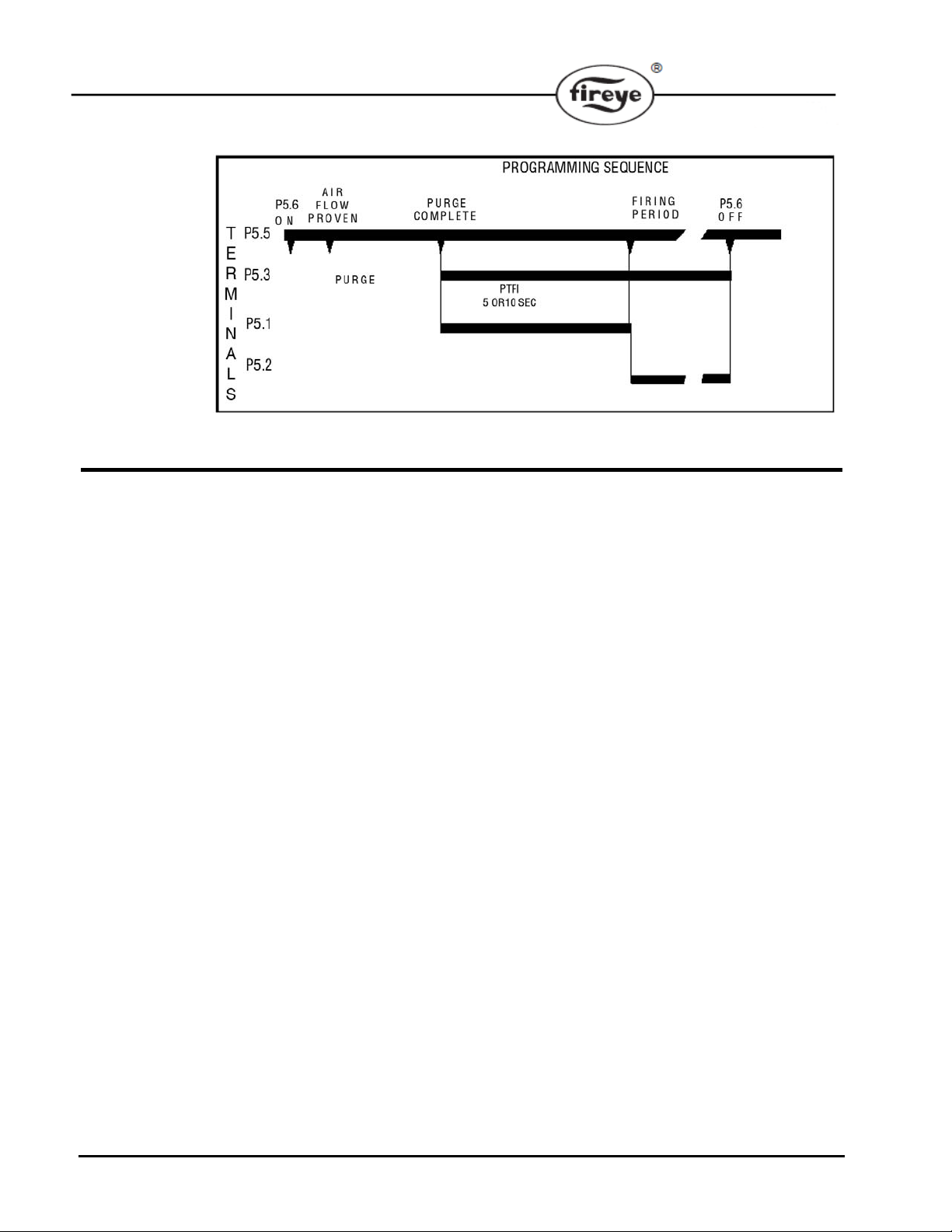
TIMING CHART
Recycle/Non-Recycle operation on loss of flame after Terminal P5.2 energized. Recycle on loss of
airflow after flame proven.
INSTALLATION TESTING
Use of Test Meter
Testing the Fireye M4RT24 Control requires the use of a test AC-DC multimeter, with a 1,000 ohm/
volt DC rating or greater, or a digital meter with 500K input impedance or greater.
With the test meter on the DC scale, and the test meter leads inserted into the test jacks. A steady
DC voltage reading of 8 to 10 volts should be obtained when the control is detecting a strong flame,
4 to 8 volts indicates an acceptable flame, and 2 to 4 volts indicates a weak flame.
NOTE: UV5-1 scanner produces a smaller dynamic range for flame signal output. With the UV5-1
scanner connected, a steady DC voltage reading of 3 volts should be obtained when the control is
detecting a strong flame, 2 to 3 volts indicates an acceptable flame, and below 2 volts indicates a
weak flame.
12
Normal Pilot Flame Test
CAUTION: Before making a pilot flame test, manually shut off the fuel supply to the main
burner.
1. Observe the pilot flame signal on the meter. If the average signal is below the minimum of
4VDC, readjust the pilot flame or realign the flame detector.
2. During the pilot flame test, if flame is not detected within the PTFI timing window, the control
will lockout. To re-establish the pilot flame trial for ignition (PTFI), manual reset of the lockout
is required, and a complete prepurge accomplished.
3. When UV flame detection is used, a test is required to verify that UV radiation from the
ignition spark is not being detected. To accomplish this, manually shut off both pilot and main
fuels. Initiate a normal start-up, and when the PTFI sequence is on, observe the meter which
should read no signal greater than 1.0VDC. If more than 1.0VDC is observed, realign the UV
scanner, and/ or shield the spark from the scanner’s view.
4. With all methods of flame detection, verify pilot flame failure response by manually shutting
off the pilot fuel and then initiate a normal start-up. With no pilot flame present, the control will
de-energize the pilot assembly at the end of the trial for ignition interv al, and the control will
lockout. Also, to verify that the ignition spark does not “give” a flame signal on UV or flame
rod applications.
Page 13
Normal Main Flame Test
1. Manually shut off the main fuel valve for a pilot ignited burner, or the secondary fuel valve for
a direct spark ignited burner.
2. Set the test meter on the DC scale and insert the test leads into the test jacks on the amplifier
module. (If the meter reads backwards, reverse the meter leads). Red - Plus, Black - Negative.
3. Initiate a normal startup.
4. When the main flame is established, the test reading should be normal: a steady DC voltage
reading of 2 to 10 volts.
5. Inadequate flame signal may be improved by:
a Assuring that the flame detector and wiring installations have followed the instructions on
pages 4 through 8.
b Assuring that the flame detector is clean and within the ambient temperature limits.
c Assuring that the flame is sufficiently large to detect.
d Assuring that the flame quality (fuel to air ratio, combustion air velocity) is satisfactory.
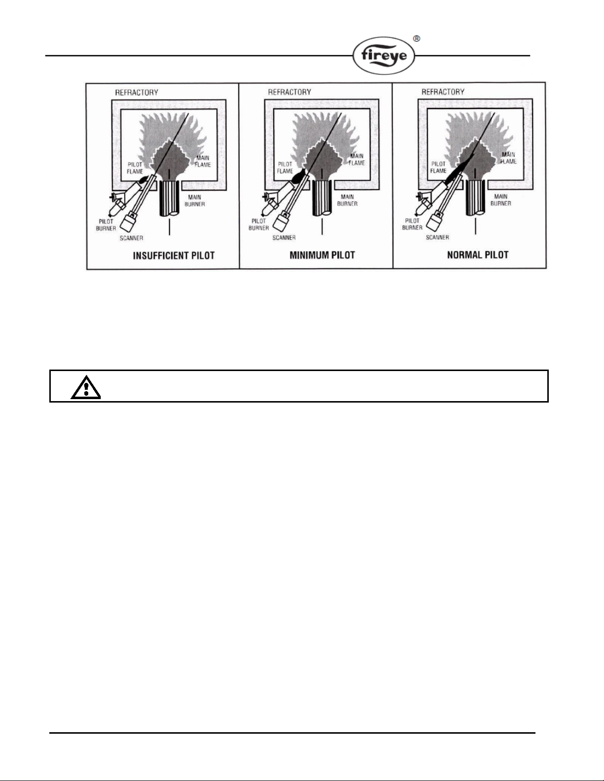
Minimum Pilot Test
This test insures that the flame detector will not sense a pilot flame too small to light the main flame
reliably. It must be made on every new installation as well as following the repositioning of the flame
detector. This procedure should not be used on a direct spark ignited burner.
1. Manually shut off the fuel to the main burner.
2. Connect a test meter to the test jacks.
3. Initiate a normal startup.
4. Reduce the fuel to the pilot until the DC voltmeter reads approximately 6 volts or when the pilot
is at the minimum to provide a reliable main flame light-off. See WARNING below. This is the
minimum pilot.
5. Slowly turn on the main fuel and insure that the main flame lights off promptly and normally.
WARNING: If light-off is delayed, shut off the power to the installation. Realign the flame
detector so that pilot flame detection sees a larger pilot flame. Repeat this test until the
main flame lights reliably with minimum pilot.
WARNING: The minimum pilot test must be accomplished by a trained and qualified
burner technician.
6. After the minimum pilot test is completed satisfactorily, increase the pilot flame to normal size,
and observe that the main flame is properly establi shed dur i ng a n ormal cycle.
13
Page 14
Flame Failure Test
1. Temporarily connect spark ignition and pilot valve to Terminal P5.3.
2. Initiate a normal startup.
3. Manually shut off all fuel and observe the loss of flame signal on the test meter.
4. If flame signal does not reduce to zero within the flame failure response time of the control,
inspect the flame scanner for potential “run-away” situation.
5. IMPORTANT: When the test is completed, reconnect the spark ignition to Terminal P5.1.
14
Page 15
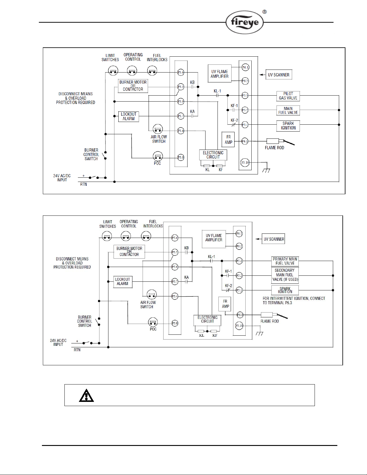
FIGURE 1. TYPICAL WIRING ARRANGEMENT FOR PILOT IGNITED BURNER.
Use moisture resistant wire suitable for at least 90°C.
FIGURE 2. TYPICAL WIRING ARRANGEMENT FOR DIRECT SPARK IGNITED BURNER
Use moisture resistant wire suitable for at least 90°C.
CAUTION: Control wiring procedures which deviate from those shown in the
diagrams may bypass safety functions designed in the control. Contact Fireye
Representative before deviating from the recommended wiring diagrams.
15
Page 16

NOTICE
WARRANTIES
When Fireye products are combined with equipment manufactured by others and/or integrated into
systems designed or manufactured by others, the Fireye warranty, as stated in its General Terms and
Conditions of Sale, pertains only to the Fireye products and not to any other equipment or to the
combined system or its overall performance.
FIREYE guarantees for one year from the date of installation or 18 months from date of manufacture
of its products to replace, or, at its option, to repair any product or part thereof (except lamps, electronic tubes and photocells) which is found defective in material or workmanship or which otherwise
fails to conform to the description of the product on the face of its sales order. THE FOREGOING
IS IN LIEU OF ALL OTHER WARRANTIES AND FIREYE MAKES NO WARRANTY OF
MERCHANTABILITY OR ANY OTHER WARRANTY, EXPRESS OR IMPLIED. Except as
specifically stated in these general terms and conditions of sale, remedies with respect to any product
or part number manufactured or sold by Fireye shall be limited exclusively to the right to replacement
or repair as above provided. In no event shall Fireye be liable for consequential or special damages of
any nature that may arise in connection with such product or part.
16
FIREYE M-4001
3 Manchester Road November 7, 2019
Derry, New Hampshire 03038 Supersedes July 16, 2019
www.fireye.com
 Loading...