

Page 1
• Adjacent to, ordirectly above,heaters, air-conditioningvents orceiling fans.
• In an areawhere thetemperature may fallbelow -30°Cor rise above 37°C.
• In areas above 93% relative humidity (RH), non-condensing.
• Near fluorescent lights. Electrical noise and flickering may affect the
operation of the heat alarm.
• Closer than 300mm to light fittings.
• In such a position that it is difficult or dangerous to reach for testing or maintenance.
• Do not sitethe alarmin an area wherewateror other liquidsmayenter thealarm.
H
OW TO INSTALL THIS HEAT ALARM
D
ANGER: E
LECTRIC SHOCK HAZARD.TURN OFF POWER TO THE HEAT ALARM CIRCUIT AT THE MAIN DIS-
TRIBUTION BOARD BY REMOVING THE FUSE OR SWITCHING THE CIRCUIT BREAKER TO THE OFF POSITION
A
ND SECURING IT
.
W
ARNING: T
HIS HEAT ALARM SHOULD BE INSTALLEDONLY BY A QUALIFIED ELECTRICIAN IN ACCOR-
D
ANCE WITH THEREGULATIONSFORELECTRICALINSTALLATIONSPUBLISHED BY THEINSTITUTION OFELEC
-
TRICAL ENGINEERS (BS 7671)AND/OR ALL PRESIDING LOCAL, REGIONAL AND NATIONALCODES.
WARNING:HEAT ALARMS SHOULD BE CONNECTEDON A SINGLE INDEPENDENT,
DEDICATED CIRCUITAT THE MAIN DISTRIBUTIONBOARD. NO OTHER ELECTRICAL
EQUIPMENT,EXCEPT COMPATIBLE SMOKEAND CO ALARMS, SHOULD BE CONNECTED TO THISCIRCUIT. IF YOUR HOMEHAS RESIDUAL CURRENT DEVICE PROTECTION ON THEELECTRICAL INSTALLATION ORON INDIVIDUAL CIRCUITS, CHECK
WITH A QUALIFIEDELECTRICIAN TO MAKE SURE THAT FAULTSON CIRCUITS SERVING SOCKET OUTLETSOR PORTABLE APPLIANCES CANNOTCAUSE INTERRUPTION
TO THE SUPPLY TO THE HEAT ALARMS.
1. Route the household AC supply/interconnect cable into the dry lining box or
Firex surface pattress.
2. Using a suitably-rated terminal block, connect the neutral supply to the blue
lead of the connector plug.
3. Using a suitably-rated terminal block, (supplied with Firex pattresses),connect
the line supply to the brown lead of the connector plug.
4. If interconnecting is desired, connect the orange or white of the connector
plug to the designated interconnect conductor of the household cable. See
note INTERCONNECTING HEAT ALARMS.
NOTE: If this is to be a single-station heat alarm, connect the orange or white
wire to an unused terminal block
5. Insert the completed connector block onto the mounting pins of the Firex Pattress or recess into dry lining box.
6. For the KF30, KF30LL ONLY :
a. Open the battery compartment door.
b. Connect a new, healthy 9V DC battery to the battery connector inside the
battery compartment. Be sure the battery is securely connected.
The heatalarm may beep briefly when the battery is installed.
c. Close the battery compartment door,snapping it into place.
d. For KF30LL, the battery door can be locked using the tamper-proof screw
provided.
7. Pass the connector plug through the mounting plate of the heat alarm, align
slots and fasten mounting plate securely to the Firex Pattress or dry lining box.
NOTE: If this is to be a single-station heat alarm, connect the orange or white wire
to an unused terminal block
8. Attach the connector plug to the pins on the back of the heat alarm. The plug
will only fit one way, and will snap into place.
9. Gently tug the connector to be sure it is attached securely.
10. Position the heat alarm on the mounting plate and turn it clockwise to lock it
into place.
11. Turnon the power to the heat alarm circuit at the main distribution board.
12. Testthe heat alarm for AC operation. See TESTINGTHE HEAT ALARM.
• Some fires are slow smouldering, low heat-producing, or are in a different
room to that in which the heat alarm is located, or the heat from the fire may
bypass the alarm – the heat alarm may not give a warning under these circumstances.
• HEATALARMSHAVE LIMITATIONS.Thisheat alarmis not guaranteedto protect
livesor property. Heatalarmsare not a substitute forinsurance.Householders
shouldinsuretheirlives andproperty.In addition,as with any electronic device,
it is possible for the heat alarm to fail at any time.
• Never paint this heat alarm.
HEAT ALARM LOCATION
Heatalarms give an audible warning when the temperatureat the alarm reaches
57°C.Heat alarms are ideal for kitchens, garages,cellars, boiler rooms, attics and
otherareas where there are normally high levels of fumes,smoke or dust which precludethe use of smoke alarms due to the risk of false alarms.
Guidanceon fire detection in dwellings is containedin BS 5839: Part 6. For normalsizedbungalows, two-story houses,flats and maisonettes, the British Standardrecommendsthat the minimum level of protection shouldcomprise smoke alarms in the
hallwaysand staircases. This minimum standardnecessitates one smoke alarmin the
hallwayof a typical bungalow or one smoke alarm on each level of a two-storyhouse.
Heatalarms should not be used in these circulation areas.If there are, for example,
longhallways, even the minimum standard may necessitateadditional interconnected
smokealarms.
If, however,the design of the dwellingdoes not comply with modern fire safety standards,or if factors such as the presence of several young children,or elderly occupantsor disabled people, or of smokers, the use of portable heatersor solid fuel fires
duringthe night, or the use of electric blankets, particularlyby the elderly, the British
Standardadvises that additional detectiondevices, installed withinrooms, may be
necessary.
The BritishStandard recommends that,if therisk justifies the provision of detectorsin
a kitchen,boiler room, or other area (except a circulationarea) in which smoke
alarmswould be likely to give false alarms, heat alarms shouldbe used. However, the
Standardalso advises that heat alarms may be installedin other rooms instead of
smokealarms, provided that the constructionenclosing the room (including the door)
can resistfire for a sufficient time after operationof a heatalarm to enable occupants
to escapesafely. However,a heat alarm is unlikely to operate early enough to save
the lifeof anyoneasleep in the room in which it is installed. Moreover,a heat alarm in
the roomof fireorigin may not give sufficient warning foroccupants to escape safely
if the door to thatroom is open. A Heat Alarm is also recommended in the Living
Room,if a smokealarm in that location, suffers nuisancealarms from smokers.
HEAT ALARM SITING
FOR BEST PROTECTION, IT ISRECOMMENDED THAT YOU INSTALL A SMOKE OR
HEATALARM INEVERY ROOM. Inaddition, it is recommended thatall smoke and
heat alarms should be interconnected.
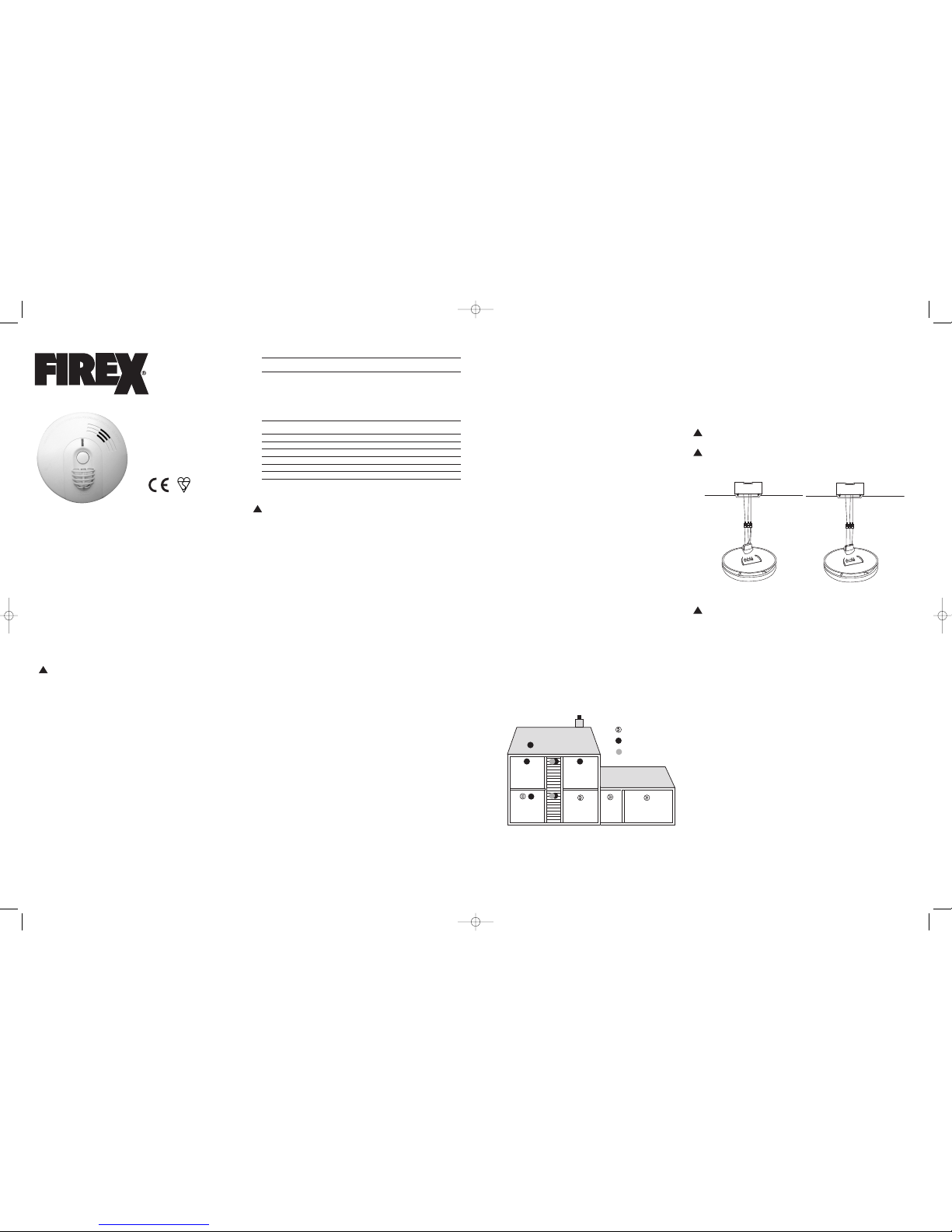
Installheat alarm on a standarddry lining boxor Firex pattress as closeto the centre of
theceiling as possible.If the centre is not practical,mount the heatalarm no closer
than300mm away from a wall orcorner.
In rooms with open joists or beams, all ceiling-mounted alarms should be located
on the bottom of such joists or beams and not up in joist channels. On sloped,
peaked or gabled ceilings, install heat alarm 90cm from highest point. If only wall
placement is possible, install no further than 150mm from ceiling.
DO NOT installheat alarms:
• Directly over the cooker, stove or oven.
• In areas with high humidity, like bathrooms or shower rooms, or areas near
dishwashers or washing machines. Install heat alarms at least 3m away from
these areas if possible.
SPECIFICATIONS
I
TEM (MODEL NUMBER) KF30, KF30LL, KF30R
E
LECTRICAL RATING 230V AC, DCBACK UP (KF30: 9V REPLACEABLE,
K
F30LL L
ONG LIFE 9
V L
ITHIUM,
KF30R: RECHARGABLE)
I
NTERCONNECTING FIREX UP TO ANY COMBINATION OF 23OTHER ALARM
SMOKE AND HEAT ALARMS MODELS,
KF1, KF1R,KF2, KF2R, KF3, KF3R,
(
OR PATTRESS WITH RELAY) 4870, 4881,4973, 4985, 4892, 4899,1SFW, 1SFWR,
2
SFW,2SFWR, 3SFW, 3SFWR
AND K
S1280
KF10, KF10LL,KF10R, KF20, KF20LL, KF20R,KF30,
K
F30LL ANDK
F30R
TEMPERATURE RATING 5
7°C
M
AXIMUM AMBIENT 37.8°C
TEMPERATURE RATING
OPERATING TEMPERATURE 0
°C
TO 4
0°C
OPERATES UP TO 93% HUMIDITY (NON-CONDENSING)
RE
COMMENDEDCOVERAGE
50M
2
RECOMMENDED SPACING 5
.3
M
MAXIMUMDISTANCE FROM WALL 7
.7
M
MA
XIMUMCEILINGHEIGHT
6M
IMPORTANT SAFETY INFORMATION
PLEASE READ AND SAVETHESE INSTRUCTIONS
WARNING
• The KF30R requires constant 230V AC power AND fully charged batteries to
operate properly. It requires 2 full days under mains power to reachfull back
up capacity. The batteries are not replaceable. Do not connect heat alarm to
any other type of device except those listed in this user guide.
• The KF30 and KF30LL heat alarm requires constant 230V AC power AND a
healthy 9V DC battery to operate properly. Removal of battery and loss or disconnection of AC power will render the alarm inoperative. DO NOT use any
other kind of battery except as specified in this user guide. Do not connect
heat alarmto any other type of device except those listed in this user guide.
• The TEST/FALSE ALARM CONTROL button accurately tests all heat alarmfunctions. DO NOT use any other test method for routine testing. Testheat alarm
weekly to ensure proper operation.
• Higher ceilings will increase the time needed by the heat alarm to detect a
fire. In most dwellings the ceiling height will keep this reaction time within
acceptable limits. However, ceilings with a height of over 6m may delay the
reaction time of the heat alarm significantly. Advice from your local distributor or Fire Brigade should be obtained when installing a heat alarm on a ceiling higher than 6m.
• This heat alarm should be installed only by a qualified electrician. The installation should comply with BS 7671 and all prevailing local, regional and national
codes.
• This heat alarm is designed to be used only as part of the protection of a single family dwelling or a house in multiple occupation (HMO) of no more than
two stories. It also may be used in conjunction with smoke alarms within individual flats or apartments in larger houses in multiple occupation, to provide
an early warning to occupants of a fire in a room within the dwelling, but a
communal fire alarm system also should be provided in such cases. DO NOT
install this heat alarm in any other buildings, such as hotels, motels, dormitories, hospitals, nursing homes or group homes of any kind. In these occupancies, a complete automatic fire detection and alarm system, complying with
BS 5839: Part 1, should be installed.
• Heat alarms should be used only in conjunction with smoke alarms, with
which the heat alarms should be interconnected, in order to provide early
warning of heat, smoke, or fire. Smoke alarms should be installed on every
level of the dwelling.
• Interconnected heat alarms and smoke alarms offer maximum protection. By
interconnecting heat alarms and smoke alarms, when one unit senses heat,
smoke, or fire, and sounds its alarm, all others will sound as well. DO NOT
connect this heat alarm to any other type of alarm except those stated in this
user guide or an approved auxiliary device.
• Heat alarms interconnected with smoke alarms may not alert every household
member every time. The alarm sounder of the heat alarm is loud in order to
alert individuals of a potential danger.However, there may be limiting circumstances where an occupant may not hear the alarm (e.g., outdoor or indoor
noise, sound sleepers, drug or alcohol usage, impaired hearing, etc.). Household members must hear the alarm’swarning sound and quickly respond to it
to reduce the risk of damage, injury, or death that may result from fire.
• Check carefully that, when any one device operates, the alarm signal given by
interconnected devices is clearly audible throughout the building, particularly
in bedrooms, where it is essential that the alarm signal will wake sleeping occupants.
• This heat alarm can sound an alarm only when it detects temperatures of 57°C
or above. Heat alarms do not sense smoke or gas. In some fires, hazardous
levels of toxic chemicals and smoke can build up before a heat alarm will operate. Temperatures may not reach 57°C to activate the heat alarm QUICKLY
ENOUGH to ensure safe escape.
HEAT ALARM FEATURES
• This heat alarmis powered from a 230V AC supply, and has a DC battery back-up
source.AC/DC heat alarms offer added protectionin the event of a power failure.
• Uniquepower connector prevents interconnectingwith incompatibleheat alarms,
CO alarms,smoke alarms, orsecurity systems.
• Items KF30,KF30LL and KF30R heat alarms can be interconnectedwith up to 23
othermodels, KF1, KF1R, KF2, KF2R, KF3, KF3R, 4870, 4881,4973, 4985, 4892, 4899,
KF10,KF10R, KF20, KF20R, KF30 and KF30R, 1SFW,1SFWR, 2SFW, 2SFWR, 3SFW
and 3SFWR,4MCO, 4MDCO. Do not connect to any other type or model of smoke,
CO, or heat alarm.
• Hush quietsunwanted alarms for up to 9 minutes.
• KF30R includespermanent rechargeablelithium batteries.
• Alarmmemory identifieswhich alarm has activated
• Optionaluse tamper-resistantfeature serves as a safeguard against tampering.
• The heat alarmwill sound a short beep about once every 40 seconds if the battery
is low.
• Multi-purposegreen and red LEDs indicate thatthe heat alarm is connected to the
AC supply,is working normally,or is in alarm.
• Loud alarmsounder – 85 decibels [dB(A)] at 3m – will sound to alert you to an
emergency.
• Testbutton checks heat alarm operation.
• KF30LLis providedwith a long life lithium battery that laststhe full life of the alarm
and a tamper-proofoption using screw provided
57°C TEMPERATURE RATING
KF30LOOSE BATTERY
KF30LLSEALED-INLITHIUM BATTERY
KF30RRECHARGEABLE
P
LEASE READ AND SAVETHIS USER GUIDE
I
nstaller:Please leavethis userguidewith
theoccupier (or,in thecaseof ahouse
inmultiple operation,with theowner).
CONTENTS
p.1 Heat Alarm Features
p.1 Specifications
p.2 Important Safety Information
p.3 Heat Alarm Location
p.3 Heat Alarm Siting
p.4 How to Install This Heat Alarm
p.5 Interconnecting Heat Alarms
p.5 Red and Green LED Indicators
p.5 False Alarm Control
p.5 Testingthe Heat Alarm
p.6 Maintenance, Cleaning,and Battery replacement-KF30 only
p.7 Repair
p.7 Fire Safety Rules and Preventing Hazardous Situations
p.7 Fire Procedure
p.7 What to Do in Case of Fire
p.8 Troubleshooting
p.8 Guarantee
BEDROOM
ATTICOFFICE
BEDROOM
HEATALARM
OPTICAL ALARM
IONISATIONALARM
KITCHENLIVING ROOM
GARAGE
UTILITY/
LAUNDRY
CEILING
INTERLINK
NEUTRAL
BROWN
ORANGEOR WHITE
BLUE
C
EILING
INTERLINK
NEUTRAL
BROWN
ORANGEOR WHITE
BLUE
KF30R
KF30, KF30LL
S
tandard Dry Lining box or Firex pattress
Standard Dry Lining box or Firex pattress
KF30
KF30LL
KF30R
USER GUIDE
BS5446pt 2:2003
LICENSENO. KM503753
WARNING:HEAT ALARMS ALONE ARENOT SUFFICIENT FOR LIFE SAFETY AS THEY ARE NOT DESIGNED TO DE-
TECT SMOKE. THEY ARE INTENDED TO DETECT TEMPERATURES OF 57°C AND ABOVE TO PROVIDE AN ADDI-
TIONAL SOURCE OF INFORMATION THAT IS SUPPLEMENTARY TO THAT PROVIDED BY SMOKE ALARMS TO
INCREASE THE PROBABILITY THAT AN EARLY WARNING WILL BE PROVIDEDAND SO ENHANCELIFE SAFETY AND
PROPERTYPROTECTION
. SEEHEAT ALARMSHAVELIMITATIONSIN THE IMPORTANT SAFETY
INFORMATION
SECTION OF THIS USER GUIDE.
!!!
!
!
1003-7203-00_(KF30_KF30LL_KF30R)_V6a:_ 2015.2.4 10:07 AM Page 1
Page 2
Theseguidelines will assist you in the event of a fire. However,to reduce the chance
thatfires will start, practice fire safety rulesand prevent hazardous situations.Contactyour local Fire Brigade for more information.
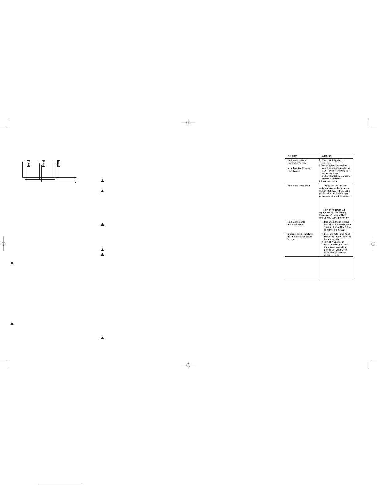
TROUBLESHOOTING
GUARANTEE
The manufacturerguarantees this productto be free from defects in material and
workmanshipunder normal use and service (“Defects”)for a period of six (6) years
fromthe date of purchase (the “Guarantee Period”).Should any Defects be discoveredwithin the Guarantee Period, the Companywill, at its option, repair or replace the
defectiveproduct provided that: (a) it is returnedduring the Guarantee Period with
postageprepaid and with proof of purchase date to the addressshown below and (b)
the Companyverifies that the claim is proper.This Guarantee does not cover damage
resultingfrom accident, improper installation,maintenanceor repair,misuse, abuse
or productmodification. This Guaranteedoes not confer any rights other than those
expresslyset out above and does not cover any claims for consequentialloss or damage.This Guarantee is offered as an extra benefit and does not affectyour statutory
rightsas a consumer.
Returnunits in a padded carton, postage prepaid,to:
FIREX PRODUCTS
KIDDE SAFETY EUROPELIMITED
MathisenWay
Colnbrook, Berkshire SL3 0HB
UnitedKingdom
Tel.: +44 (0) 1753 685148
www.smoke-alarms.co.uk
FIRE SAFETY RULES AND PREVENTING
HAZARDOUS SITUATIONS
Siting,testing, andtaking care of heat and smokealarms is just one stepin helping to
protectyour family andhome from fires. Youmust also reducethe chance that fireswill
startin your home and increaseyour chances ofescaping if a fire does start.At a
minimum,your home firesafety program shouldinclude the followingguidelines:
• Use smoking materials properly – never smokein bed or when sleepy or under
the influenceof alcohol or other drugs.
• Keep matches and other sources of ignitionaway from children.
• Store flammable materials in propercontainers and never store or use them
nearopen flames or sparks.
• Keep electrical appliances and theirleads in good working condition, and do not
overloadelectrical circuits.
• Keep fireplaces, chimneys, and barbecuegrills clean, and make sure they are
properlysited away from combustible materials.
• Keep portable heaters and open flames suchas candlesaway from combustible
materials.
• Do not allow rubbish to accumulate.
• Have the electrical wiring in your house checkedby a qualifiedelectrician at
leastevery 10 years (or more often as it ages).
• Never leave cooking unattended.
FIRE PROCEDURE
If you hear theheat or smoke alarm sounding, and you have not pushed the testbutton,it is warning you of a dangeroussituation.You will need torespond immediately.
Toprepare forsuch occurrences,develop family escapeplans, discussthem with all
householdmembers,and practice them regularly.For yoursafety, as a minimum,you
shoulddo the followingto have more effectivefire safety.
• Draw a floor plan of your homeand find all ways to escapeif there is a fire. On
theground floor,consider whetherwindows can be used forescape. On upper
floors,consider whetherexternal rescuewill be possibleif escape routes are
blockedby fire or smoke.
• Expose everyoneto the sounds of the heat alarmand of the smoke alarmand explainwhat the sounds mean.Show them how to checkto see if doors are hot beforeopening them, howto stay close to the floor andcrawl along the floorto stay
belowdangerous smoke,fumes and gases, andhow to use the alternativeexit if
a dooris hot. Instruct themnot to open the door if the dooris hot.
• Decide on a meeting placea safe distance fromyour house and make sureall
membersof your householdunderstand theyshould go and wait for youthere if
thereis a fire. Explain tochildren that they mustbe ready to leave the houseby
themselvesif necessary.
• Hold fire drills everysix (6) months to makesure everyone, evensmall children,
knowwhat to do to escape safely.
• Know where to go to call theFire Brigade from outsideyour house.
• Provide emergencyequipment, suchas fire extinguishers,and teach your family
howand when to use this equipment.
WHAT TO DO IN CASE OF A FIRE
Afteryou have prepared family escape plans and practicedthem with your family, you
haveincreased their chances of escaping safely.Review the following ruleswith your
familywhen you have fire drills, so everyone will rememberthem in a real fire.
1. Don’t panic, stay calm. Your safe escape may depend on thinking clearly and
remembering what you have practiced.
2. Get out of the house, following your planned escape route, as quickly as
possible. Do not stop to collect anything or to get dressed.
3. Opendoors carefully only after feeling to see if they are hot. Do not open a door
if it is hot; use an alternativeescape route. If your escape route is blocked,go to
a windowand shout for help. If necessary, stuff clothingor other materials in the
gapsround the room door to stop smoke from entering until help arrives.
4. Stay close to the floor; smoke and hot gases rise toward the ceiling.
5. Keep doors and windows closed unless you open them to escape.
6. Meet at your pre-arranged meeting place after leaving the house.
7. Call the Fire Brigade as soon as possible from outside yourhouse. Give your
full address, including the name of the town or village.
8. Always call the Fire Brigade as soon as possible, even if a fire seems small.
9. Never re-enter a burning orsmoke-filled building.
2. Firmly depress and hold the TEST/Hush button for at least five (5) seconds. The
heat alarm will sound a loud beep for about three (3) times a second. The
alarm may sound for up to ten (10) seconds after the TEST/Hush button is released. NOTE: If heat alarms are interconnected, all heat and smoke alarms
should sound an alarm within three (3) seconds after any test button is pushed
and the tested heat alarm sounds.
3. If the heat alarm does not sound, turn off the power to the heat alarm circuit at
the main distribution board and check the wiring. Retest the heat alarm.
!WARNING:IF
THE HEATALARM SOUNDS
, A
ND THE HEATALARM IS NOT BEING TESTED
, T
HE HEAT
ALARM IS SENSINGA TEMPERATURE OF
5
7°C
OR ABOVE.
THE ALARMSOUND REQUIRES YOUR
I
MMEDIATEATTENTION ANDACTION. EVACUATE THEDWELLING IMMEDIATELY!
MAINTENANCE AND CLEANING
In additionto weekly testing, this heat alarm must be cleanedperiodically to remove
dust,dirt and debris.
DANGER: ELECTRIC SHOCK HAZARD.
TURN OFF THEAC SUPPLY TO THEHEAT ALARM ATTHE MAIN DISTRIBUTION BOARD BYREMOVING THE FUSEOR SWITCHING THE APPROPRIATECIRCUIT BREAKER TO THE OFFPOSITION BEF
ORE CLEANINGTHE HEAT ALARM.
W
ARNING:
H
EATALARMS ARE LIFE-SAVING DEVICESAND SHOULD BECARED FOR PERIODICALLY
CLEANING
Clean the heat alarm at least once annually to remove dust, dirt and debris. Always
turn off the AC power to the heat alarm before cleaning it.
Using the soft brush or wand attachment to a vacuum cleaner,vacuum all sides and
the cover of the heat alarm. Be sure that all vents are free from debris. If necessary,
turn off the AC power and use a cloth dampened with warm water to clean the heat
alarm cover.
IMPORTANT:Do not attempt to removethe cover or clean insidethe heat alarm.
THIS WILL INVALIDATE YOUR GUARANTEE. Failure to properly clean and maintain
this heat alarm may result in impaired operation and possible failure and will invalidate the guarantee.
WARNING:BATTERIES NOTREPLACEABLE INTHE KF30LL ORKF30R.
M
ODEL KF30R HASPERMANENTLY MOUNTEDRECHARGEABLE LITHIUM BATTERIESTHAT ARE DESIGNED
TO LAST THE USEFULLIFE OF THE ALARM.
BATTERY REPLACEMENT– KF30 ONLY
Alwaysturn off the AC power to the heat alarm before replacing the battery. Replace
the batteryat least once annually, or immediatelywhen the low battery signal
soundsonce a minute, even though the heat alarm is receivingAC power. Use only
the following batteries as replacements in this heat alarm: Energizer 522 ; Duracell
MN1604 or MX 1604; FDK CP-V9Ju; Ultralife U9VL-J-P.
CAUTION: DANGER OF EXPLOSION IF BATTERYIS INCORRECTLY REPLACED. USEONLY THE BATTERIES
SPECIFIED IN THE USER USER GUIDE
.
WARNING:D
O NOT USE ANY OTHER TYPE OF BATTERY, EXCEPT AS SPECIFIED IN THIS USER GUIDE. DO
N
OT USE RECHARGEABLE BATTERIES
.
1. Turnoff the AC power supply to the heat alarm at the main distribution board.
2. Insert a small screwdriver into the slot in the mounting plate and turn the heat
alarm counterclockwise to detach the alarm.
3. Gentlypulldown the heatalarm.Be carefulnot to separateanywire connections.
4. Pull out the connector plug from the back of the heat alarm.
5. From the back of the heat alarm, remove battery door screw and lift the tab to
open the battery compartment door.
6. Remove the battery from the compartment. Disconnect the drained battery
from the battery compartment and discard.
7. Connecta new, healthy9V battery to the connector. The batterywill fit only one
way.Be sure the batteryconnector is securelyattached to thebattery terminals.
8. Place the battery into the battery compartment.
9. Close the battery compartment door. Push down until it snaps into place. Install battery door screw.
10. Using the TEST button, test the heat alarm to verify 9V DC battery back-up. See
TESTING THE HEAT ALARM.
11. Replace the connector plug. The connector will snap into place. Gently tug the
connector to be sure it is attached properly.
12. Reattach the heat alarm to the mounting plate by turning the heat alarm clockwise until it snaps into place.
13. Turnon the AC power and test the heat alarm using the TEST button. See
TESTING THE HEAT ALARM.
REPAIR
CAUTION:DO NOT ATTEMPT TO REPAIR THIS HEAT ALARM.DOING SO WILL INVALIDATEYOUR GUARANTEE.
If the heat alarm is not operating properly, see TROUBLESHOOTING. If necessary,
and if the heat alarm is still under warrant, pack it in a well-padded carton and send
it, with Proof of Purchase postage prepaid, to the address given at the end of this
user guide.
If the heat alarm is no longer under guarantee, have a qualified electrician replace
the heat alarm immediately with a comparable Firex brand heat alarm.
INTERCONNECTING HEAT ALARMS
Use 1.5mm2 minimum solid or stranded cable with a rating of 230V. When interconnecting heat alarms, CO alarms or smoke alarms, the maximum cable length
between anytwo should be 450m for 1.5mm2 cable (20 ohm loop resistance.)
DO NOT connect to any other type or model of heat alarm, CO alarms or smoke
alarm. Connect all interconnected heat and smoke alarms to a single final circuit.
Wiring must conform to I.E.E. Regulations for Electrical Installations (BS 7671).
RED AND GREEN LED INDICATORS
Thisheat alarm features a red and green LED indicator that can be seen throughthe
clearlight pipe on the top of alarm. The LEDs indicate the following:
GREEN
ON –AC power is present.
OFF – AC power is not present.
R
ED
BLINKSONCE EVERYA 5 MINUTES AND 20 SECONDS –Mains power is
presentindicating normal operation.
BLINKSONCE EVERY 10 SECONDS – False Alarm Control activated.
OFF – DC power is not present.
BLINKSONCE A SECOND and unit is sounding alarm – senses 57°C
temperatureor greater.
OFF and unitis soundingalarm – Another interconnected smoke/heatalarm in
the networkhas sensed smoke or 57°C and is signaling this alarm.
3 RAPID FLASHESAT 40 SECOND INTERVAL - Indicateswhich alarm has
previouslydetected an alarm condition.
HUSH CONTROL
WARNING:BEFORE USING THE ALARM’S HUSH FEATURE, FULLYIDENTIFY THE
SOURCE OF THEHEAT BUILD UP ANDMAKE SURE THAT THEAREA IS SAFE.
TO ACTIVATE CONTROL PUSHAND RELEASE THE TEST/FALSEALARM CONTROL
BUTTON IN THECENTER OF THE ALARM. THEALARM WILL SILENCE IMMEDIATELY
AND THE REDLIGHT (LED) WILL BLINK APPROXIMATELY EVERY10 SECONDS FOR
THE NEXT 10MINUTES. THIS FEATURE ISTO BE USED ONLYWHEN A SAFE CONDITION IS KNOWNTO EXIST.
The Hush feature will silence the alarm for approximately 9 minutes. A rapid rise in
temperature will override the False Alarm Control and cause the unitto sound an
alarm.
After 9 minutes the heat alarm will revert to normal operation. If the unit still detects
a dangerous situation the alarm will sound again.
If interconnected alarms are installed, the unit that detects the high temperature
and sounds the alarm cannot be inadvertently silenced by the TEST/Hush button of
other units. In this case all of the alarms will continue to sound for as long as a dangerous situation is detected or until the TEST/Hush button of the initiating alarm is
pressed.
If the alarm does not go into False Alarm Control and continues to sound its alarm,
the heat in the area is too high and a dangerous situation may exist – take
emergency action.
TESTING THE HEAT ALARM
WARNING:TEST EACH HEAT ALARM AND SMOKE ALARM TO BE SURE THAT EACH IS INSTALLED
CORRECTLY AND IS OPERATING PROPERLY
.
S
TAND AT ARM’S LENGTH FROM THE HEAT ALARM WHEN TESTING. THE ALARM SOUNDER IS LOUD TO
ALERT YOU TO AN EMERGENCY AND CAN BE HARMFUL TO HEARING
.
T
EST THE HEAT ALARM WEEKLY AND UPON RETURNING FROM HOLIDAY, ORWHEN THE HOUSE HAS BEEN
UNOCCUPIED FOR SEVERAL DAYS
.
Testall heat alarms weekly by doing the following:
1. Check the TEST/HUSH button. If the green LED above the
test button is ON, the heat alarm is receiving AC power.
ORANGE OR WHITE ORANGE OR WHITE
FOR INTERCONNECTING: USE A MINIMUM OF 1.5mm2CABLE
NEUTRAL
LINE
NOTE:Colorsshown correspondto electricalcodesin the United Kingdom.Colors may
varyin othercountries.
once every 40 seconds
3 chirps every 40 seconds
(KF30, KF30LL Only).
KF30R:
KF30
KF30LL: This alarm has a long life lithium
battery to last the full life of the alarm.
If the alarm beeps every 40 seconds
there is a unit fault and it needs replacing.
Ten (10) year end of life warning.
Alarm must be replaced
(REPLACE IMMEDIATELY! )
NOTE: PUSH AND HOLD TEST BUTTON
1003-7203-00
!
!!!
!
!!!
1003-7203-00_(KF30_KF30LL_KF30R)_V6a:_ 2015.2.4 10:07 AM Page 2
 Loading...