

Page 1

PRODUCT OVERVIEW
PRODUCT APPLICATION:
The Firex Series Duct Smoke Detectors provide early detection of smoke and products of combustion present in the air moving through an HVAC
duct in commercial, industrial and residential applications.
These devices are designed to prevent the recirculation of smoke in areas by the air handling systems, fans and blowers. Complete systems
may be shut down in the event of smoke detection.
NOTE
For the correct installation of a duct smoke unit, please refer to the NFPA 72E (Standard for Automatic Fire Detectors) and NFPA 90A (Standard
for Installation of Air Condition and Ventilation Systems.)
This detector is not intended for open area protection nor should it be used for early warning detection or replace a regular fire detection system.
Maple Chase provides a special U.L. 50 listed, NEMA 3R rated weatherproof enclosure separately (Model 555) which should be used in
appropriate outdoor applications for protection from the elements. Other installations above the roof line (attics, banjo type roofs, etc.) do not
require the special Model 555 weatherproof enclosure as long as the Maple Chase duct smoke detectors are not exposed to dripping water or
other environmental elements. The Model 555 weatherproof enclosure should be used in all applications where environmental elements are a
concern or local code requires a weatherproof enclosure for proper installation. All installations of our duct smoke detectors and weatherproof
enclosures should be done in accordance with all applicable electrical and building codes.
PRODUCT DESCRIPTION
:
The Firex Smoke Detector is fitted with a mounting base that will accept an Ionization Detector Head Model # 2850-450 or Photoelectric Detector
Head Model # 2850-550. The duct unit supports 2 sets of form “C” and 1 form “A” Alarm Contacts and 1 form “C” Trouble Contact. The trouble
contact supervises the presence of the input power and removal of the detector head.
THE TROUBLE CONTACTS (TERMINALS 4-15-5) ARE SHOWN IN THE NON-ENERGIZED CONDITION.
The trouble contact will not
operate in the event of a smoke alarm.
The Firex Duct Detector models 2650-760 and 2650-761 will operate on one of the following input voltage sources: 24VAC, 24VDC, 115VAC
and 230VAC.
The duct smoke detector units are designed to operate in duct widths from 12 inches to 10 feet wide with an air velocity between 300 and 4,000
feet per minute. To verify correct installation, the pressure differential between the input and exhaust tubes should be measured using a
Magnehelic pressure gauge or equivalent. An acceptable reading must be between 0.01 and 1.2 inches of water.
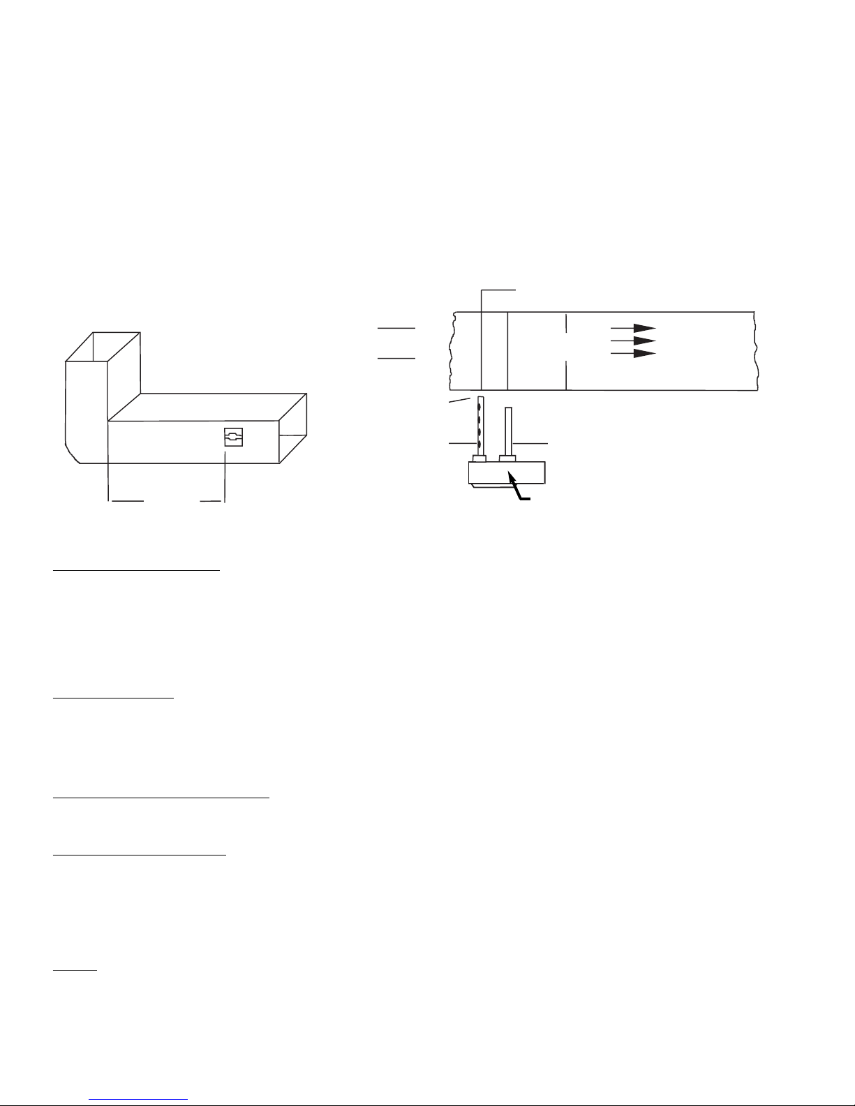
For a Duct Smoke Detector unit to operate correctly, it must be installed 6 duct widths from any obstruction i.e. elbows, deflector plates, filters,
dampers, etc. In situations where the criteria cannot be met, deviations are acceptable providing they meet the pressure differential
requirements.
SAMPLING TUBES:
The principal of operation of a duct detector is based on the Venturi effect. Two tubes extend into the HVAC duct. Air flowing through the duct
is forced into the air intake tube via the air intake holes, and passes over the detector head. The air will be drawn out via the exhaust tube back
into the HVAC duct. (7” exhaust tube provided in the installation kit.)
When the particles of smoke suspended in the air stream reach the alarm threshold of the detector head, the unit will go into alarm.
Duct Unit Installation
DUCT SMOKE LOCATION PRE-REQUISITES:
This guideline contains general information on duct smoke detector installation, but does not preclude the NFPA documents listed. Maple Chase
Company assumes no responsibility for improperly installed duct detectors. To determine the correct installation position for a Firex Duct Smoke
Detector, the following factors must be considered.
1) A uniform non turbulent airflow of between 300 ft/min to 4,000 ft/min. must be present in the HVAC duct. To determine the duct
velocities examine the engineering specifications that define the expected velocities or use an Alnor model 6000P
velocity/meter (or equivalent).
2) In order to prevent stratification, duct smoke units, where possible, must be located a minimum of six duct widths down stream
from a source of turbulence i.e. elbows, deflector plates, filters, dampers, and inlets.
MODEL 2650-760 Ionization
MODEL 2650-761 Photoelectric
INSTALLATION INSTRUCTIONS FOR
UNIVERSAL DUCT SMOKE DETECTORS
R
AP 186 MA 2650-760; 01/01
Page 2
In installations where it is impossible to adhere to the six duct width requirement, units can be installed closer but as far from inlets, bends or
deflector plates as possible. Should this situation arise, check velocity readings in the duct prior to the duct smoke unit installation. Ensure the
duct smoke unit pressure differential complies with the unit specifications. The pressure differential between the input sampling tube and
exhaust tube for the Firex series duct smoke unit should be greater than 0.01 inches of water and less than 1.2 inches of water.
3) Identify a location for the installation of the duct unit that will permit easy access for viewing and serviceability.
4) Install duct units in the return air side of an HVAC unit prior to the air being exhausted from the building or diluted with outside air.
5) When installing duct smoke units down stream of filters, fires occurring in the filters will be detected, but if the filters become blocked
insufficient air flow through the duct unit will prevent the correct operation of the duct detector.
6) Where possible, install duct detectors upstream of air humidifiers and downstream of dehumidifiers.
7) To prevent false alarms, the duct detector should not be mounted in areas of extreme high or low temperatures, in areas where high
humidity exists or in areas where the duct may contain gases or excess dust.
6 Duct Widths
Minimum
Bend or Other
Obstruction
Insert Red Stopper
This End of Inlet Tube
Air Flow
Tube Support Hole Only for Ducts
Greater than 3 Feet Wide
Duct Width
Air Flow
Direction
Set
Screw
2650 Duct Smoke
Detector
SAMPLING TUBE ASSEMBLY:
Sampling tubes are to be ordered separately in one of the 3 standard lengths.
552 For duct widths of 1.0’ TO 2.5’
553 For duct widths of 2.5’ TO 5.0’
554 For duct widths of 5.0’ TO 10.0’
The standard sampling tubes are steel tubes with air intake holes drilled down the entire length of the tube. These tubes must be cut to length
and must span the entire width of the duct. Sampling tubes over 3.0 feet must be supported on the opposite side of the duct. To ensure the
correct operation of the sensing tube, the red end cap (red stopper in installation kit) must be inserted in the end of the air intake sampling tube.
DUCT PREP
ARATION
:
For ease of duct unit installation, remove mounting template from the installation kit. Remove paper backing from the
mounting template and affix it to the duct at the desired location. Using the template as a guide, drill 2 mounting holes (3/32” diam.) for the
12 X 1/2” sheet metal screws packaged in the installation kit.
Drill or punch 1 1/4” holes for sampling tubes, using the template as a guide. Clean all holes.
MOUNTING DUCT SMOKE DETECTOR
Mount the housing to the duct using 2 #12 x 1/2” sheet metal screws. Install the intake tube making sure the holes are facing the air flow. Tighten
the latch screw to secure the tube. Install the exhaust tube. Tighten the latch screw to secure the tube.
AIR SAMPLING VERIFICA
TION:
To ensure correct operation of the duct unit use a Magnehelic differential pressure gauge or Dwyer model 4000 to determine the differential
pressure between the inlet and exhaust tubes. The differential pressure between the two tubes should be greater than 0.01 inches of water and
less than 1.2 inches of water.
Electrical Installation
WIRING
Prior to connecting power to the Firex 2650-760 and 2650-761 duct units, determine the correct input voltage and ensure it is connected to the
correct terminals. (Refer to power connections)
24VAC/DC,Terminals (9, 10); 115VAC, Terminals (115, H, G); 230VAC, Terminals (220, H, G).
Holes Face
Air Flow
Inlet Tube
Exhaust Tube
Installed Downstream of
Air Flow
Do Not Insert
Red Stopper
AP 186 MA 2650-760; 01/01
Page 3

(+) PILOT OUT
TERMINAL CONNECTIONS
:
NC C NO
RELAY
Firex Duct Unit
In alarm, 7 and 18
will open,
interrupting supply
to fan
18
8
Fan Supply Source
7
10A
ALARM
CONTACT
1
23456789
10
G
220
115
H
11
12 13 14 15
16 17
18 19
20
GROUND
24 VDC COM (-)
10A
*TROUBLE
CONTACTS
NO
POWER
INPUT
24
VAC/VDC
10A
ALARM
CONTACT
NC
NC
NO
C
C
POWER
INPUT
220/240
VAC
120
VAC
NC
NO
C
C
(+)
ALARM
CONTACT
L
(-) (+)
AUX
POWER
OUT
2A
ALARM
CONTACT
NO
*TROUBLE CONTACTS ARE SHOWN
IN NON-ENERGIZED CONDITION.
UNDER NORMAL OPERATION
CONTACTS WILL BE REVERSED.
TEST PROCEDURES
OPERATIONAL TESTING
To determine the correct operation of the Firex Duct Smoke Detector, ensure power is connected and the green pilot LED is illuminated.
The LED on the detector head flashes during the standby mode. The LED on the detector head will be permanently illuminated when smoke is
detected and the head is in alarm.
With the air handling unit shut down, and the clear cover removed, press and hold the test/reset button on the Firex Duct Unit. The red alarm
LED on the circuit board will be illuminated and the alarm relay outputs will change state. Using a multimeter set to OHMS (or continuity buzzer
function on the meter) place the meter probes on the following terminals and ensure the contacts are closed (continuity) (18, 8), (6,17) when
releasing the test/reset button these contacts will open.
The trouble contacts (4, 15, 5) will not change state in the event of a fire alarm, operational or functional testing. The trouble contacts can be
tested by rotating the Apollo detector head counter-clockwise and removing the detector head. This action will extinguish the pilot (green) LED
and cause the trouble contacts to change state, (4, 15) will be closed (continuity) (5, 15) will be open circuit. Replacing the detector head and
rotating it clockwise until it locks, will cause the green pilot LED to be illuminated and the unit will be operational, terminals (4, 15) will be open
circuit and (5, 15) will be closed (continuity).
FUNCTIONAL TESTING
Once operational testing is concluded the unit requires functional testing to determine the correct operation of the detector head.
RESET INPUT
CAUTION:
For terminals (7, 8, 18), (6, 16, 17), (13, 14) do not use looped wire under terminals. Break wire run to provide supervision of connections. To
test the correct operation of the duct smoke unit, excluding the detector head (see functional testing page 4) remove detector head and connect
one of the appropriate dedicated power sources to the applicable terminals (See above). Replace detector head and the unit will be energized
(The green LED will be illuminated). When pressing the test/reset button the red alarm LED will be illuminated. In the event of a fire alarm,
certain equipment may have to be shut down. A shut down will be achieved by interrupting the supply source to that particular piece of equipment
when wired as indicated below.
EXAMPLE
:
FAN
AP 186 MA 2650-760; 01/01
Page 4

MAGNET TESTING: Place the magnet provided with the instruction kit on top of the housing between the raised sections above the detector
head (as indicated on the unit cover). Allow at least five (5) seconds for alarm initiation. Remove magnet and reset detector.
SMOKE TESTING:
Using smoke test canister with testing nozzle (Part Number 565), insert the test gas nozzle into the test point on the unit
cover. Press can against cover to release gas into chamber. CAUTION:
Do not spray gas for more than 1/2 second. Overuse of test gas
facility will result in detector contamination.
After 15 to 20 seconds the detector head will go into alarm, illuminating the detector head LED and causing the duct unit functions to operate,
relays will change state and the remote accessories if attached will function. Please allow several minutes for the gas to evaluate the chamber
before the detector may be reset.
If no test gas is available to conduct the testing, remove cover and blow smoke from a cotton wick or punk directly at the head to cause alarm.
The alarm indicator will illuminate within one minute.
Should testing be required for simulated fire conditions, smoke bombs placed in the duct may not be suited for the particular detector head
selected and installed.
Ionization Detector Head 2850-450 utilizes a radioactive source as its means of detection and will detect smoke particles of between .1 and 1
micron in size.
Photoelectric Detector Head 2850-550 operates on the principle of light scatter and will detect smoke particles of between 1 and 10 microns in
size.
When purchasing smoke bombs for functional testing, ensure smoke particle sizes comply with the criteria as described above.
MAINTENANCE
Each installation location must be assessed on its own merits. If the protected area is of a very dirty nature then the Firex Duct units will have
to be checked and cleaned on a Quarterly basis or when cleaning is required.
As a guideline the detector head should be cleaned every six months or as required.
The best methods of cleaning are to vacuum the detector head thoroughly or to blow the detector head out using compressed air.
Do not use chemicals to clean the detector head housing as this could contaminate the detector head and damage the casing.
Sensing tubes must be inspected and cleaned in accordance with the schedule as determined above, to allow the free flow of air through the
sensing tube.
AP 186 MA 2650-760; 01/01
Model Number:
Detector Model Number:
S65 Ionization Detector Head 2850-450
S65 Photoelectric Detector Head 2850-550
POWER REQUIREMENTS
QUIESCENT CURRENT ALARM CURRENT
24V AC 39.4mA 24V AC 128.7mA
24V DC 13.5mA 24V DC 59.3mA
115V AC 13.8mA 115V AC 27.0mA
230V AC 7.9mA 230V AC 16.0mA
RELA
Y CONTACT RATINGS:
Alarm contacts: 2 form “C” rated at 10AMPS @ 115V AC resistive, 1 Form A @ 2AMPS
Trouble contacts: 1 Set form “C” rated at 10AMPS @ 115V AC resistive
Air velocity: 300 to 4,000 ft/min
Ambient temperature: Model 2650-760 32
o
F to 155oF (0oC to 68oC)
: Model 2650-761 32
o
F to 100oF (0oC to 38oC)
Humidity: 10% to 85% R.H. no condensation
Material: Gray plastic backbox with clear plastic cover
Dimensions: L-13 1/2”, X H-4 1/2”, Depth - 2 1/4”
Max. net wt.: 3 lbs.
Radioactive element: For Firex 2650-760 (Ionization model)
Americium 241, 0.9 micro curie
Do not expose to corrosive atmospheres.
PRODUCT SPECIFICATIONS
2650-760 Ionization
24V AC/DC, 115V AC, 230V AC
2650-761 Photoelectric
24V AC/DC, 115V AC, 230V AC
Maple Chase Company
2820 Thatcher Road
Downers Grove, Illinois 60515 USA
Telephone +1 630 719 5500 Facsimile +1 630 719 4400
Technical Service Telephone +1 800 445 8299
E-mail mctechservices@maplechase.com
www.maplechase.com
TM
Page 5

RED
BLACK
BLACK
RED
RED
BLACK
RED
BLACK
Fire Alarm Control Panel Wiring
UL
Listed
Fire
Alarm
Control
Unit
5
15
5
15
13
14
13
14
Firex Detector
#1
Firex Detector
#2
EOL
End
of
Line
Fig. 1
12
19
19
REMOTE ACCESSORY WIRING
vvv
vvv
1
20
4
19
vvv
15
20
YELLOW
“TROUBLE
LED
KEY OR
PUSH BUTTON
“TEST/RESET
SWITCH
RED
“ALARM”
LED
AND
OR
HORN/
STROBE
_
_
GREEN
PILOT
LED
TROUBLE CONTACTS
CANNOT BE CONNECTED
TO FIRE ALARM PANEL
WHEN USING THIS
OPTION
JUMPER
HEAD OR COVER
REMOVAL
TEST / RESET
ALARM
(WHEN NOT INTERCONNECTED)
PILOT
2
Remote Accessories Approved For Use With This Detector
535 Remote Alarm 542 Remote Alarm, Pilot, Horn, key-operated Test/Reset Switch
536 Remote Alarm, push button Test/Reset Switch 543 Remote Alarm, Pilot, Horn
537 Remote Alarm, Pilot, push-button Test/Reset Switch 544 Remote Alarm, Trouble, Pilot, Horn, key-operated Test/Reset Switch
538 Remote Alarm, key-operated Test/Switch 545 Horn/Strobe, red housing, clear cover
539 Remote Alarm, Pilot, key-operated Test/Reset Switch 546 Horn/Strobe, white housing, opaque cover
540 Remote Alarm, Pilot 547 Horn/Strobe, white housing, clear cover
541 Remote Alarm Horn
AP 186 MA 2650-760; 01/01
Page 6

- BLK
DETECTOR INTERCONNECTION WIRING
COMMON FUNCTIONS
1
20
1
20
1
20
12
20
12
20
12
20
13
14
19
20
13
14
19
20
13
14
19
20
ALL RELAYS OPERATE WITH
SINGLE ALARM
30 DETECTORS MAX
ALL RELAYS OPERATE WITH SINGLE
ALARM
INDIVIDUAL HORN/STROBE OPERATE
ON ALARMED DETECTOR ONLY
30 DETECTORS MAX
ALL RELAYS OPERATE WITH
SINGLE ALARM
ALL HORN/STROBES OPERATE
WITH SINGLE ALARM
10 DETECTORS MAX
COMMON TEST/RESET
30 DETECTORS ONLY
NORMALLY
OPEN RESET
SWITCH
Unit #1 Unit #2 Unit #3
Unit #1 Unit #2 Unit #3
Unit #1 Unit #2 Unit #3
Unit #1 Unit #2 Unit #3
12 12 12
H
+ RED
- BLK
H
+ RED
- BLK
H
+ RED
- BLK
13
14
19
20
13
14
19
20
13
14
19
20
12 12 12
H
+ RED
- BLK
H
+ RED
- BLK
H
+ RED
AP 186 MA 2650-760; 01/01
 Loading...