

Page 1
INSTALLATION INSTRUCTIONS
FW4-H and FW2-H
These installation instructions are for the FW-4, FW4-H, FW-2 and the FW2-H FIREWOLF Smoke Detectors.
CAUTION!!!
Install this and all life safety devices in accordance with
applicable NFPA standards, local codes, and the authorities having jurisdiction. Failure to follow these instructions may result in failure of the detector to initiate
an alarm condition. Napco Security Systems, Inc. and
the original equipment manufacturer, are not responsible for detectors that have been improperly installed,
tested, or maintained.
For testing and cleaning information, ref er to these instructions and/or call the NAPCO fax request line at
(631) 842-3291. Also refer to NFPA-72 Chapter 5 for
Automatic Fire Detectors for installation guidelines and
Chapter 7 for testing and maintenance requirements.
Use “3M” Weatherban # 606 non-flammable sealing
compound to seal field wiring conduit openings in the
mounting back box. Compliance with this request may
reduce the occurrence of the “STACK EFFECT”.
SPECIFICATIONS SMOKE DETECTOR DATA
Detector
FW-2 FW2-H FW-4 FW4-H
Type of Detector
Photoelectric
(2 wire baseless)
Photoelectric
(2 wire baseless)
Photoelectric
(4 wire baseless)
Photoelectric
(4 wire baseless)
Working Voltage
8.0 - 35.0 VDC 8.0 - 35.0 VDC 8.0 - 35.0 VDC 8.0 - 35.0 VDC
Voltage
Waveform
Filtered DC
15% ripple max.
Filtered DC
15% ripple max.
Filtered DC
15% ripple max.
Filtered DC
15% ripple max.
Max. Alarm
Current
Limit current to
150mA @ 35.0
VDC
Limit current to
150mA @ 35.0
VDC
55mA @ 35.0
VDC
55 mA @ 35.0
VDC
Max. Surge
Current
200µA 200µA 200µA 200µA
Average
Standby Current
38µA @ 12 VDC
55µA @ 24 VDC
70µA @ 35 VDC
38µA @ 12 VDC
55µA @ 24 VDC
70µA @ 35 VDC
38µA @ 12 VDC
55µA @ 24 VDC
70µA @ 35 VDC
38µA @ 12 VDC
55µA @ 24 VDC
70µA @ 35 VDC
Compatibility
Identifier
HD-6 HD-6 N/A N/A
Sensitivity Test
Feature
Built-In Test
Feature
Built-In Test
Feature
Built-In Test
Feature
Built-In Test
Feature
NAPCO
Control Panel
Compatibility
See Wiring
Diagram Below
See Wiring
Diagram Below
N/A N/A
Heat Element
Rating
N/A 135° F N/A 135° F
Note:
When mounting detector on a wall, it must be between 4” and 12” from the ceiling.
Trim Ring 3” OCT 4” Oct
Box Mounting
Wiring
: Connect wiring to the bases as shown in the wiring diagrams that follow. Detectors may be mixed on the same initiating
loop as long as the number of two-wire powered detectors does not exceed the specifications of the control panel. See Specification
Table above.
CAUTION: Connect wiring to terminals as shown. Do not loop wire under terminals. Break wire run to provide supervision.
FW-4 Wiring Diagram
FW-2 Wiring Diagram
Compatible Control Panels:
FW-C2Z, FW-C4Z, FW-C4EZ
GEM-P3200
GEM-P9600
GEM-P800, GEM-P8 01
GEM-P816, GEM-P1632
NAPCO Express XP600
MA3000
Note:
For cross listings with additional manufacturers and models pending,
contact the NAPCO Technical Support Department for the latest listings at
(800) 645-9440. Also available online at www.napcosecurity.com (go to the
Firewolf folder and download FW2_WI1009_ADDM).
CAUTION
The FW-2 requires current
Limiting to no more than 150mA
@ 35.0 VDC
Magnum Alert® is a Registered trademark of NAPCO. Gemini,™ Signature™ and NAPCO Express™ are Trademarks of NAPCO.
Napco Security Systems, Inc.
333 Bayview Avenue * Amityville, NY 11701
Phone: (800) 645-9445 (631) 842-9400 Fax: (631) 789-3383
U.L. Listed
Control
Panel
U.L. Listed
Power
Supply
*24VDC
U.L. Listed
Power
Supply
*12VDC
* = Use 12 or 24VDC - CANNOT BE USED SIMULTANEOUSLY
LISTED
END-OF-LINE
RELAY
12 OR 24VDC
LISTED
END-OF-LINE
DEVICE
R
®
LISTED
END-OF-LINE
DEVICE
U.L. LISTED
COMPATIBLE
CONTROL PANEL
Page 2
To mount the FW- 4 and the FW-2 Baseles s Det ec tor
Head to the Trim Ring, do th e fol lowing:
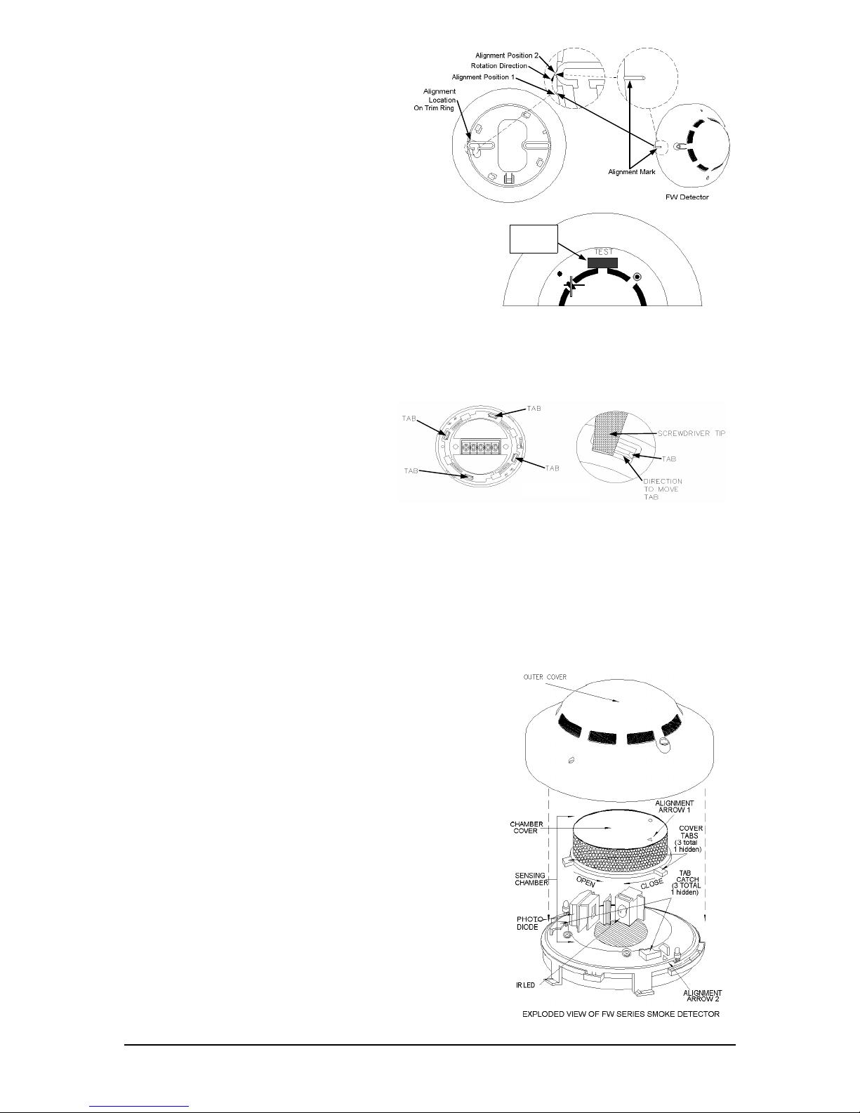
1. Place the Baseless Detector Head over the Trim Ring with
its back towards the Trim Ring.
2. Place the detector with the Alignment Mark at Alignment
Position 1 (see di agram).
3. Bring the detector together with the Trim Ring.
4. Turn the detector clockwise and when the Alignment Mark
is at Alignment Pos ition 2 the detector will have s napped
into place (see diagram).
5. Refer to the diagram for visual reference to the alignment
marks.
FIREWOLF SENSITIVITY TEST FEATURE and INSTALLATION VERIFICATION
Note: The FW- 4 and the FW-2 have a built-in automatic sensitivity test feature that will automatically indicate a change in sensitivity.
1. In normal conditio n both LEDs flash Green.
2. When the sensitivity drifts outside of its sensitivity limits, both LEDs flash Red (e.g., when the unit needs cleaning).
3. In the alarm state b o th LEDs are on Red c on t inuously.
4. When the condition exists as stated in 2 above, the device needs to be cleaned or returned to the factory for servicing. Refer to the following instructions f or cleaning information:
MANUAL CLEANING PROCEDURE
Tools you will nee d:
∗
2 small screwdrivers (1/8” wide)
∗
A small soft-bristled artist’s paint brush
∗
Denatured alcohol
∗
Clean dry compressed air.
NOTE:
Use only lint-free materials when cleaning the chambers of the photoelectric smoke detector. Use of fibrous materials may result in
false alarms.
Clean the Detector
CAUTION: Do not attempt to remove the insect screen.
1. Remove the Outer Cover of the detect or as specified and set aside.
2. Place the detector in the palm of your left hand and grasp the Chamber Cover
with your right hand. Twist the Chamber Cover counter-clockwise until the
Cover Tabs clear t he T ab Catches. Lift and separ a te the Chamber Cover and
Outer Cover from the Optical Unit.
3. Swab the Optical un it with denature d alcohol using a small soft-bristled brush.
4. Use dry clean compressed air to dry the optical unit and to remove any remaining particles.
5. Clean the Chamber Cover and Outer Cover in the same manner.
Reassemble the Detector
1. Locate the Alignment Arrows on both the Chamber Cover and the Optical Unit.
2. Set the Chamber cover onto the Optical Unit while making sure that Alignment
Arrow 1 and Alignment Arrow 2 are aligned with each an other.
3. Holding the detector in your left hand and grasping the Chamber Cover with your
right hand, rotate the Chamber Cover clockwise until the Cover Tabs snap into the
Tab Catches.
4. Place the Outer Cover of the detector nose down on a flat surface.
5. Align the Outer Cover Nub with the Alignment Arrow on the enclosure (two Orientations are possible, only one will fit properly).
6. With the Outer Cover Nub aligned with the Alignment Arrow, press down firmly on
the back of the detector. The detector will s nap i nto th e Outer Cover. The detector is now ready to be returned to the Trim Ring from which it was removed.
7. The detector should be re-tested by performing the test procedure described in
this document.
Note:
If after testing, the detector is not working within the prescribed limits, then
return it to the manufacturer for servicing.
Remove and Disassemble the Detector
Follow the steps in this section to prepare the detector for cleaning:
1. Remove the detector from the trim ring.
2. Disassemble detector by placing one screwdriver under the tab as show n in Diagram 2B (above).
3. Then place the second screwdrive r under the next adj acent TAB pushing it the direction shown in Diagram 2B.
4. Push the screwdriver outward from the center of the detector and lift the Enclosure upward.
5. Do the same with the second screwdriver, but do not remove it--keep it in place.
6. Ta ke the first screwdriver and place it under the third TAB adjacent to the second TAB. Push the TAB outward and lift
the Enclosure upward.
7. With three tabs f reed, the Enclosure will finally remove easily with the ap pl ication of the screwdriver.
WI 972C 10/04
TESTING THE FW- 4 and the FW-2 INSTALLATION
For go/no-go testing, a magnet will be required.
1. Hold the magnet j ust UNDER the word “TEST” as shown on Diagram 2A.
2. The detector should alarm within 10 seconds (If control panel is programmed for
Fire Alarm Verification, it may take up to 30 seconds).
3. The detector’s LEDs should be on Red continuously and any control panel indicating appliances should activate.
4. Silence the system and activate the control panel reset to reset smoke detector.
5. The smoke detector LEDs should flash Green.
DIAGRAM 2B
DIAGRAM 2A
HOLD
MAGNET
HERE
© NAPCO 2004
 Loading...