

Page 1
HotView
Hardware Installation Guide
HotPort 6000 Series
HotViewProTM
Indoor and Outdoor Wireless Mesh Nodes
Manual Revision 0.95 022807
The contents of this Installation Guide are subject to change without notice.
Please refer to the Firetide web site, www.firetide.com, for current versions.
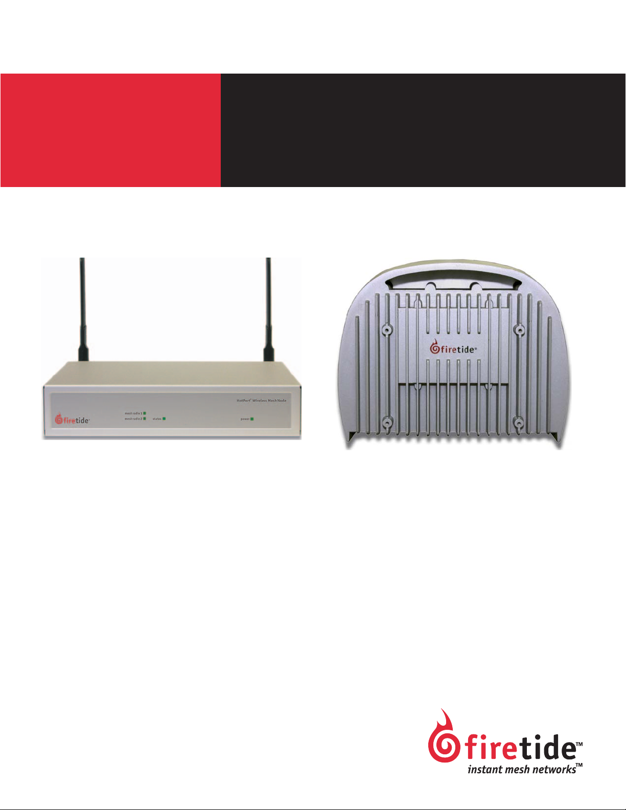
Series 6200 - Outdoor NodeSeries 6100 - Indoor Node
Page 2
Firetide Limited End User Product Warranty
Pursuant to all provisions described herein, Firetide hardware products and
Firetide antennas are warranted for one (1) year from the date of purchase
against defects in the build materials and workmanship. Firetide does not
warrant that the Products will meet any requirements or specifications of
any End User Customer. This warranty applies to the entire Firetide product,
including the AC power adapter.
Pursuant to all provisions described herein, Firetide sof tware products are
warranted for ninety (90) days from the date of purchase against defects in
the build materials and workmanship. Firetide also warrants that the Software will materially conform to the documentation supplied by Firetide with
the Software. In the event that the Software fails to materially conform to
the documentation and an authorized Firetide reseller is notified in writing
of such failure within the warranty period, Firetide or its reseller shall use
commercially reasonable efforts to promptly correct the nonconformity.
Firetide does not warrant that the use of the Software will be uninterrupted
or error free.
The above warranties are void if the alleged defect cannot be verified by
Firetide or if, as determined by Firetide, the product failure was due to tampering, abuse, misuse, accident, shipping, handling, or storage; or if the
product has been installed, used, or maintained in a manner not described
in the product user manual; or if the product has been altered in any way;
or if product serialization has been altered. Any attempt to disassemble or
repair the product by anyone other than Firetide immediately voids this
warranty.
This warranty applies only to the original End User purchaser of the product
and may not be transferred to any other individual or entity.
THE FOREGOING ARE THE EXCLUSIVE WARRANTIES APPLICABLE TO THE PRODUCT INCLUDING THE SOFTWARE, AND THE EXCLUSIVE REMEDY FOR DEFECTS
IN THE PRODUCT. FIRETIDE DISCLAIMS ALL OTHER WARRANTIES, WHETHER
EXPRESS, IMPLIED, STATUTORY OR OTHERWISE, INCLUDING BUT NOT LIMITED
TO IMPLIED WARRANTIES OF MERCHANTABILITY, NON-INFRINGEMENT OR FIT-
NESS FOR A PARTICULAR PURPOSE. SOME LAWS DO NOT ALLOW THE EXCLUSION OF IMPLIED WARRANTIES SO TO THAT EXTENT THIS LIMITATION MAY NOT
APPLY TO YOU.
In no event will Firetide be liable for any special, incidental, consequential,
punitive or indirect damages whatsoever (including, without limitation,
damages for loss of profits, business interruption, loss of information, or
other pecuniary loss) arising out of the use or inability to use the product
or the performance, interruption or failure of the product, irrespective of
the cause of action, even if Firetide has been advised of the possibility of
such damages. Firetide’s cumulative liability for all claims arising out of or
in connection with this warranty will not exceed the amount paid by the
original End User purchaser to purchase the product. The amounts payable
for the product are based in part on these limitations and these limitations
shall apply notwithstanding the failure of essential purpose of any remedy.
Some jurisdictions do not allow the exclusion or limitation of incidental or
consequential damages, so to that extent the above limitations or exclusions may not apply to you.
By using the product the original End User purchaser agrees to and is bound
by these terms and conditions.
In the event that a product fails to meet this warranty and Firetide’s authorized reseller is notified in writing of such failure within the warranty period, Firetide shall, at its own discretion, either repair the product or replace
it with the same or a functionally-equivalent product free of charge. Replacement products may contain refurbished materials in whole or in part.
Firetide will honor this warranty provided the product is returned through
an authorized Firetide reseller or dealer with shipping charges prepaid,
along with a proof of purchase describing the original purchase date and
product serial numbers if applicable. The authorized reseller must acquire a
Return Materials Authorization (RMA) number from Firetide prior to returning any product. Firetide does not accept shipments of defective products
without shipping charges prepaid.
Safety Instructions & Explanation of Graphic Symbols
The HotPort outdoor wireless mesh node must be installed by a qualified professional such as a licensed electrician. Failure to install this equipment properly may result in equipment damage and personal injury or death.
This symbol is intended to alert the user to the presence of non-insulated dangerous voltage that may be
of sufficient magnitude to constitute a risk of lethal
electric shock to persons.
This symbol is intended to alert the user to the presence of important operating, maintaining and servicing instructions in the literature accompanying the
HotPort node. Failing to comply with this instruction
may result in electrical shock.
This symbol is intended to alert the user to the presence of important operating, maintaining and servicing instructions in the literature accompanying the
HotPort node. Failing to comply with this instruction
may result in a hazard.
Copyright Notice: ©2003-2007 Firetide, Inc. All rights reserved.
Trademarks: Firetide, the Firetide logo, Instant Mesh Networks, HotPort, and HotPoint are trademarks of Firetide, Inc. All other trademarks are the property of their respective owners.
2 HotPort 6000 Series Mesh Nodes February 2007
Page 3

Contents
HotPort Node Installation . . . . . . . . . . . . . . . . . . . . . . . . . . . . . . . . . . . . . . . . . . . . . . . . . . . . . . . . . . . . . . . . . . . . . . . . . . . . . . . . . . . . . .5
Unpacking . . . . . . . . . . . . . . . . . . . . . . . . . . . . . . . . . . . . . . . . . . . . . . . . . . . . . . . . . . . . . . . . . . . . . . . . . . . . . . . . . . . . . . . . . . . . . . . . 5
Indoor Mesh Node . . . . . . . . . . . . . . . . . . . . . . . . . . . . . . . . . . . . . . . . . . . . . . . . . . . . . . . . . . . . . . . . . . . . . . . . . . . . . . . . . . . . . . . . .5
Antenna Assembly . . . . . . . . . . . . . . . . . . . . . . . . . . . . . . . . . . . . . . . . . . . . . . . . . . . . . . . . . . . . . . . . . . . . . . . . . . . . . . . . . . . . . . . . .5
Power . . . . . . . . . . . . . . . . . . . . . . . . . . . . . . . . . . . . . . . . . . . . . . . . . . . . . . . . . . . . . . . . . . . . . . . . . . . . . . . . . . . . . . . . . . . . . . . . . . .5
Documentation . . . . . . . . . . . . . . . . . . . . . . . . . . . . . . . . . . . . . . . . . . . . . . . . . . . . . . . . . . . . . . . . . . . . . . . . . . . . . . . . . . . . . . . . . . .5
Compact Disk (CD) . . . . . . . . . . . . . . . . . . . . . . . . . . . . . . . . . . . . . . . . . . . . . . . . . . . . . . . . . . . . . . . . . . . . . . . . . . . . . . . . . . . . . . . . .5
Outdoor Mesh Node . . . . . . . . . . . . . . . . . . . . . . . . . . . . . . . . . . . . . . . . . . . . . . . . . . . . . . . . . . . . . . . . . . . . . . . . . . . . . . . . . . . . . . . .5
Antenna Assembly . . . . . . . . . . . . . . . . . . . . . . . . . . . . . . . . . . . . . . . . . . . . . . . . . . . . . . . . . . . . . . . . . . . . . . . . . . . . . . . . . . . . . . . . .5
Power . . . . . . . . . . . . . . . . . . . . . . . . . . . . . . . . . . . . . . . . . . . . . . . . . . . . . . . . . . . . . . . . . . . . . . . . . . . . . . . . . . . . . . . . . . . . . . . . . . .5
Documentation . . . . . . . . . . . . . . . . . . . . . . . . . . . . . . . . . . . . . . . . . . . . . . . . . . . . . . . . . . . . . . . . . . . . . . . . . . . . . . . . . . . . . . . . . . .5
Compact Disk (CD) . . . . . . . . . . . . . . . . . . . . . . . . . . . . . . . . . . . . . . . . . . . . . . . . . . . . . . . . . . . . . . . . . . . . . . . . . . . . . . . . . . . . . . . . .5
Planning Your Installation . . . . . . . . . . . . . . . . . . . . . . . . . . . . . . . . . . . . . . . . . . . . . . . . . . . . . . . . . . . . . . . . . . . . . . . . . . . . . . . . . . . . . .6
Staging Considerations . . . . . . . . . . . . . . . . . . . . . . . . . . . . . . . . . . . . . . . . . . . . . . . . . . . . . . . . . . . . . . . . . . . . . . . . . . . . . . . . . . . . . . 6
Required Tools and Supplies . . . . . . . . . . . . . . . . . . . . . . . . . . . . . . . . . . . . . . . . . . . . . . . . . . . . . . . . . . . . . . . . . . . . . . . . . . . . . . . . . . 6
Indoor Node Installation . . . . . . . . . . . . . . . . . . . . . . . . . . . . . . . . . . . . . . . . . . . . . . . . . . . . . . . . . . . . . . . . . . . . . . . . . . . . . . . . . . . . . . .7
Outdoor Node Installation . . . . . . . . . . . . . . . . . . . . . . . . . . . . . . . . . . . . . . . . . . . . . . . . . . . . . . . . . . . . . . . . . . . . . . . . . . . . . . . . . . . . . .8
Preparing the Unit. . . . . . . . . . . . . . . . . . . . . . . . . . . . . . . . . . . . . . . . . . . . . . . . . . . . . . . . . . . . . . . . . . . . . . . . . . . . . . . . . . . . . . . . . . 8
Preparing the Site for Mounting . . . . . . . . . . . . . . . . . . . . . . . . . . . . . . . . . . . . . . . . . . . . . . . . . . . . . . . . . . . . . . . . . . . . . . . . . . . . . . . 8
Safety Considerations . . . . . . . . . . . . . . . . . . . . . . . . . . . . . . . . . . . . . . . . . . . . . . . . . . . . . . . . . . . . . . . . . . . . . . . . . . . . . . . . . . . . . .8
Weatherproofing . . . . . . . . . . . . . . . . . . . . . . . . . . . . . . . . . . . . . . . . . . . . . . . . . . . . . . . . . . . . . . . . . . . . . . . . . . . . . . . . . . . . . . . . . .8
Preparing Earth Ground . . . . . . . . . . . . . . . . . . . . . . . . . . . . . . . . . . . . . . . . . . . . . . . . . . . . . . . . . . . . . . . . . . . . . . . . . . . . . . . . . . . . .8
Mounting the Antennas. . . . . . . . . . . . . . . . . . . . . . . . . . . . . . . . . . . . . . . . . . . . . . . . . . . . . . . . . . . . . . . . . . . . . . . . . . . . . . . . . . . . . . 9
Mounting Guidelines . . . . . . . . . . . . . . . . . . . . . . . . . . . . . . . . . . . . . . . . . . . . . . . . . . . . . . . . . . . . . . . . . . . . . . . . . . . . . . . . . . . . . . .9
Mounting the Bracket . . . . . . . . . . . . . . . . . . . . . . . . . . . . . . . . . . . . . . . . . . . . . . . . . . . . . . . . . . . . . . . . . . . . . . . . . . . . . . . . . . . . . . 10
Mounting Guidelines . . . . . . . . . . . . . . . . . . . . . . . . . . . . . . . . . . . . . . . . . . . . . . . . . . . . . . . . . . . . . . . . . . . . . . . . . . . . . . . . . . . . . .10
Wall Mounting . . . . . . . . . . . . . . . . . . . . . . . . . . . . . . . . . . . . . . . . . . . . . . . . . . . . . . . . . . . . . . . . . . . . . . . . . . . . . . . . . . . . . . . . . . .10
Pole Mounting . . . . . . . . . . . . . . . . . . . . . . . . . . . . . . . . . . . . . . . . . . . . . . . . . . . . . . . . . . . . . . . . . . . . . . . . . . . . . . . . . . . . . . . . . . .10
Using Mounting Straps . . . . . . . . . . . . . . . . . . . . . . . . . . . . . . . . . . . . . . . . . . . . . . . . . . . . . . . . . . . . . . . . . . . . . . . . . . . . . . . . . . . . .10
Mounting the Node . . . . . . . . . . . . . . . . . . . . . . . . . . . . . . . . . . . . . . . . . . . . . . . . . . . . . . . . . . . . . . . . . . . . . . . . . . . . . . . . . . . . . . . . 11
Connecting Cables. . . . . . . . . . . . . . . . . . . . . . . . . . . . . . . . . . . . . . . . . . . . . . . . . . . . . . . . . . . . . . . . . . . . . . . . . . . . . . . . . . . . . . . . . 12
Power Options - Outdoor Nodes. . . . . . . . . . . . . . . . . . . . . . . . . . . . . . . . . . . . . . . . . . . . . . . . . . . . . . . . . . . . . . . . . . . . . . . . . . . . . . . 13
Power Supply . . . . . . . . . . . . . . . . . . . . . . . . . . . . . . . . . . . . . . . . . . . . . . . . . . . . . . . . . . . . . . . . . . . . . . . . . . . . . . . . . . . . . . . . . . . .13
DC Power . . . . . . . . . . . . . . . . . . . . . . . . . . . . . . . . . . . . . . . . . . . . . . . . . . . . . . . . . . . . . . . . . . . . . . . . . . . . . . . . . . . . . . . . . . . . . . .13
Building a Custom Ethernet Cable . . . . . . . . . . . . . . . . . . . . . . . . . . . . . . . . . . . . . . . . . . . . . . . . . . . . . . . . . . . . . . . . . . . . . . . . . . . . . 13
Appendix A - Contacting Firetide . . . . . . . . . . . . . . . . . . . . . . . . . . . . . . . . . . . . . . . . . . . . . . . . . . . . . . . . . . . . . . . . . . . . . . . . . . . . . . . .14
Appendix B - Connector Wiring . . . . . . . . . . . . . . . . . . . . . . . . . . . . . . . . . . . . . . . . . . . . . . . . . . . . . . . . . . . . . . . . . . . . . . . . . . . . . . . . .15
HotPort Outdoor Node Ethernet Transition Cable Pin Descriptions . . . . . . . . . . . . . . . . . . . . . . . . . . . . . . . . . . . . . . . . . . . . . . . . . . . . 15
Power Connector Pin Descriptions . . . . . . . . . . . . . . . . . . . . . . . . . . . . . . . . . . . . . . . . . . . . . . . . . . . . . . . . . . . . . . . . . . . . . . . . . . . . . 15
Appendix C - Specifications . . . . . . . . . . . . . . . . . . . . . . . . . . . . . . . . . . . . . . . . . . . . . . . . . . . . . . . . . . . . . . . . . . . . . . . . . . . . . . . . . . . .16
Common Specifications . . . . . . . . . . . . . . . . . . . . . . . . . . . . . . . . . . . . . . . . . . . . . . . . . . . . . . . . . . . . . . . . . . . . . . . . . . . . . . . . . . . . . 16
Wireless Interface . . . . . . . . . . . . . . . . . . . . . . . . . . . . . . . . . . . . . . . . . . . . . . . . . . . . . . . . . . . . . . . . . . . . . . . . . . . . . . . . . . . . . . . .16
Outdoor Unit Specifications. . . . . . . . . . . . . . . . . . . . . . . . . . . . . . . . . . . . . . . . . . . . . . . . . . . . . . . . . . . . . . . . . . . . . . . . . . . . . . . . . . 17
Indoor Unit Specifications. . . . . . . . . . . . . . . . . . . . . . . . . . . . . . . . . . . . . . . . . . . . . . . . . . . . . . . . . . . . . . . . . . . . . . . . . . . . . . . . . . . 17
Appendix D - Regulatory Notices . . . . . . . . . . . . . . . . . . . . . . . . . . . . . . . . . . . . . . . . . . . . . . . . . . . . . . . . . . . . . . . . . . . . . . . . . . . . . . . .18
USA . . . . . . . . . . . . . . . . . . . . . . . . . . . . . . . . . . . . . . . . . . . . . . . . . . . . . . . . . . . . . . . . . . . . . . . . . . . . . . . . . . . . . . . . . . . . . . . . . . .18
Canadian Compliance Statement . . . . . . . . . . . . . . . . . . . . . . . . . . . . . . . . . . . . . . . . . . . . . . . . . . . . . . . . . . . . . . . . . . . . . . . . . . . .18
Firetide Instant Mesh Networks 3 February 2007
Page 4

Caution! Risk of electric shock!
POWER LINES CAN BE LETHAL
Do not install the HotPort outdoor mesh node where possible contact with power lines can be made. Antennas, poles, towers, guy
wires, or cables may lean or fall and contact these lines. People may
be injured or killed if they are touching or holding any part of equipment when it contacts electric lines. Make sure there is NO possibility that equipment or personnel can come in contact directly or
indirectly with power lines.
ASSUME ALL OVERHEAD LINES ARE POWER LINES
The horizontal distance from a tower, pole or antenna to the
nearest power line should be at least twice the total length
of the pole/antenna combination. This will ensure that the
pole will not contact power if it falls either during or after installation.
SURVEYING THE SITE
Look over the entire site before beginning any installation and anticipate possible hazards. Never assume anything without checking
it out for yourself! Don’t take shortcuts!
TO AVOID FALLING, USE SAFE PROCEDURES WHEN WORKING AT
HEIGHTS ABOVE GROUND
Select equipment locations that will allow safe and simple in-
•
stallation.
Don’t work alone. A friend or co-worker can save your life if an
•
accident happens.
Don’t attempt repair work when you are tired. Not only will
•
you be more careless, but your primary diagnostic tool -
deductive reasoning - will not be operating at full capacity.
Use approved non-conducting ladders, shoes, and other safety
•
equipment. Make sure all equipment is in good repair.
If a tower or pole begins falling, don’t attempt to catch it. Stand
•
back and let it fall.
If anything such as a wire or pole does come in contact with a
•
power line, DON’T TOUCH IT OR ATTEMPT TO MOVE IT. Instead,
save your life by calling the power company.
Don’t attempt to erect antennas or towers on windy days.
•
MAKE SURE ALL TOWERS AND POLES ARE SECURELY GROUNDED,
•
AND ELECTRICAL CABLES CONNECTED TO ANTENNAS HAVE LIGHTNING ARRESTORS. This will help prevent fire damage or human
injury in case of lightning, static build-up, or short circuit within
equipment connected to the antenna. The HotPort outdoor node
has built-in lightning protection. Be sure that any other equipment connected to the HotPort node also has the same level of
protection.
The base of the antenna pole or tower must be connected direct-
•
ly to the building protective ground or to one or more approved
grounding rods, using 10 AWG ground wire and corrosion-resistant connectors.
Refer to the National Electrical Code for grounding details.
•
IF AN ACCIDENT SHOULD OCCUR WITH THE POWER LINES
DON’T TOUCH THAT PERSON, OR YOU MAY BE ELECTROCUTED.
•
Use a non-conductive dry board, stick, or rope to push or drag
•
them so they no longer are in contact with electrical power.
Once they are no longer contacting electrical power, administer
•
CPR if you are certified.
Immediately have someone call for medical help.
•
Do not open the cover
Dangerous voltages inside.
•
No serviceable parts inside.
•
Refer to qualified service personnel.
•
Unit must be disconnected from power prior to servicing.
•
Unit has tamper-evident labeling that indicates when the cover has been removed.
•
4 HotPort 6000 Series Mesh Nodes February 2007
Page 5

HotPort Node Installation
This hardware installation guide describes how to install the HotPort node safely. The HotPort is intended to be installed by trained professionals. Be sure to read and understand all installation and safety instructions before proceeding with the installation.
Table 1. Summary of HotPort 6000 Series Mesh Nodes
Model Use No. of Radios
6101 Indoor, Worldwide, 2.4, 4.9, 5 GHz 1
6102 Indoor, Worldwide, 2.4, 4.9, 5 GHz 2
6201 Outdoor, Worldwide, 2.4, 4.9, 5 GHz 1
6202 Outdoor, Worldwide, 2.4, 4.9, 5 GHz 2
Unpacking
The HotPort node package contains the following items. If you are missing any of these items, contact your Firetide reseller.
Indoor Mesh Node
HotPort node in plenum-rated enclosure.
•
Antenna Assembly
Two detachable 2.4 Ghz omni-directional antennas.
•
Two detachable 5 Ghz omni-directional antennas.
•
Note: HotPort nodes come with two pairs of staging antennas. Use
these antennas to determine which RF frequency band (2.4 or 5 GHz)
to use in your installation location. After you decide, order spectrumspecific (that is, 2.4 or 5 GHz) antennas from Firetide. Firetide offers
a range of antennas; refer to the Firetide Antenna Guide for current
offerings.
Power
Power brick with NEMA5-15 (US) to IEC cord. Other IEC cords are
•
available separately .
Note: Series 6100 nodes have an improved, positive-retention DC power cable, and will NOT work with existing Firetide Hotport 3100 and
3500 series power supply bricks.
Documentation
6100 Series Quick Install Guide.
•
Warranty and registration card.
•
Compact Disk (CD)
HotView sof tware.
•
HotView Pro User Guide.
•
HotPort 6000 Series Hardware Installation Guide
•
Warranty/Registration Card.
•
EULA.
•
Outdoor Mesh Node
HotPort node in NEMA-4X enclosure with weatherproof caps.
•
Two N to reverse-polarity SMA adapters.
•
Lockable bracket kit for pole and wall mounting. Designed to fit
•
37 mm to 50 mm (1.5 in to 2.0 in) poles. The mounting bracket
also has slots for mounting straps for attaching to larger diameter or irregularly shaped poles.
Weatherized Ethernet transition cable (2 m (6.6 ft)), circular,
•
watertight, IP67-rated female to RJ-45/RJ-45 male connector
kit with Bulgin connector housing.
Antenna Assembly
Two detachable 2.4 Ghz omni-directional antennas.
•
Two detachable 5 Ghz omni-directional antennas.
•
Power
Power cord with NEMA 5-15 (US) plug. Other cords are available
•
separately.
Note: Series 6200 nodes will work with existing Firetide Hotport 3200
and 3600 series power supply bricks.
Documentation
6200 Series Quick Install Guide.
•
Warranty and registration card.
•
Compact Disk (CD)
HotView sof tware.
•
HotView Pro User Guide.
•
HotPort 6000 Series Hardware Installation Guide.
•
Warranty/Registration Card.
•
EULA.
•
Firetide Instant Mesh Networks 5 February 2007
Page 6

Planning Your Installation
HotPort 6000 Series nodes are easy to install. They are mechanically compatible with existing HotPort nodes. 6000 Series nodes
form their own mesh, however - they will not mesh with 3000 Series
nodes.
Staging Considerations
You should set up and test your nodes indoors, on a bench or table, before installing them. This will allow you to pre-configure the
nodes so that they are all on the same RF channel, etc.
Set up your HotPort node in a lab with all other HotPort units using
1.
the two provided antennas.
Make all the necessary cable connections and power the Hot-
2.
Port units.
Required Tools and Supplies
The following tools and supplies must be provided by the customer:
#2 Philips screwdriver
•
Small adjustable wrench
•
Wire cutters to cut tie wraps around cables
•
Ladders, lifts, and/or platforms to install the HotPort node on
•
poles and structures
10 AWG grounding cable to connect the HotPort node to earth
•
ground
Grounding connectors and grounding rod
•
Weatherproofing kit – this kit provides electrical tape and butyl
•
mastic. Check your local distributor for weatherproofing antennas and coaxial cables.
Hose clamps, band clamps, U-bolts, or similar brackets, suitable
•
for attaching the HotPort node to your chosen antenna mast.
6200 Series outdoor nodes are improved compared to earlier designs. For new installations, a single weatherproof power cord is
provided. No external ‘brick’ is used. The 6200 Series can power up
to two peripherals via PoE, as well. For existing installations, the
6200 Series can accept the DC power from supplies used to power
3200 Series and 3600 Series nodes. The 6200 Series will also fit the
existing pole mount.
Install the HotView software on a workstation and connect the
3.
workstation to a HotPort node (see the HotView User Guide for
information about installing and using HotView).
Use HotView to configure the HotPort nodes and create a small
4.
mesh network. Configure and test the network settings you
plan to use.
Hose clamps, band clamps, U-bolts, or similar brackets, suitable
•
for mounting the antennas to your chosen antenna mast.
If you need to build a custom cable to connect a wired-Ethernet device to your HotPort, you will need an RJ-45 crimping tool and a
Catgory 5 Ethernet cable with at least one RJ-45 connector to connect a peripheral to the HotPort.
The following tools and supplies are optional:
Cordless screwdriver #2 Philips
•
Cordless drill
•
Antenna stand (used to mount the antenna pole)
•
6 HotPort 6000 Series Mesh Nodes February 2007
Page 7
Indoor Node Installation
8mpadaYjqÛ9jY[c]l DYafÛDgmflaf_Û9jY[c]l
?glGgjlÛD]k`ÛEg\]
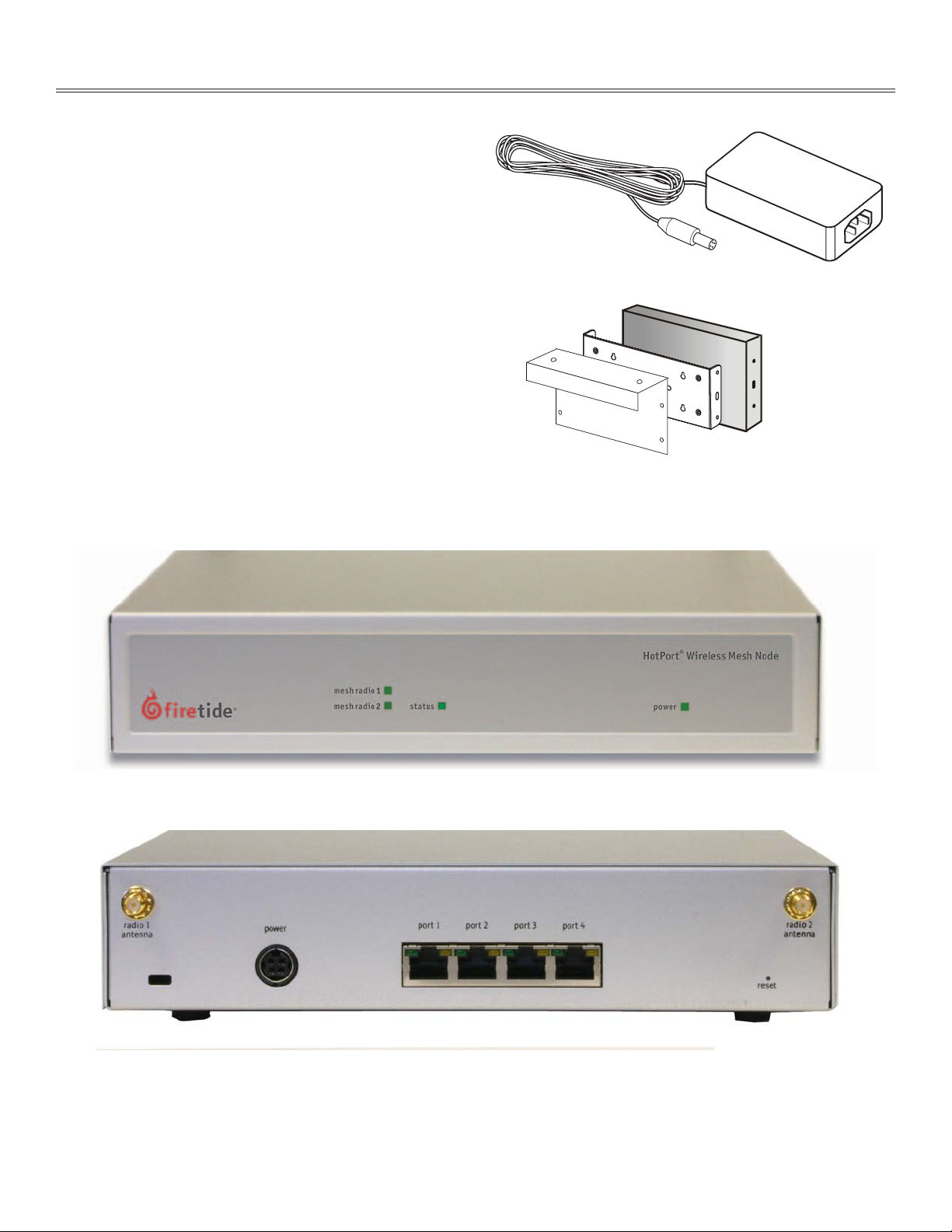
Indoor node installation is straightforward. Place the unit on a
table or shelf, or use the optional bracket to attach it to a wall, ceiling, or cubicle partition. Attach the antennas, keeping in mind that
all antennas on all units should be parallel - typically vertical. Apply
power. The power LED should illuminate immediately; after about 60
to 90 seconds, the status LED should switch to steady green.
Firetide recommends that you power up and configure all nodes on
a table or bench before deployment. Use HotView or HotView Pro to
configure your mesh.
Note the location of the reset button in the lower right corner of the
rear panel. A paperclip can be used to reset the unit after it has fully
booted and the status light has come on.
Figure 3. HotPort 6100 Series Mesh Node - Front View
Figure 1. AC Power Brick
Figure 2. Optional Mounting Bracket
Figure 4. HotPort 6100 Series Mesh Node - Rear View
Firetide Instant Mesh Networks 7 February 2007
Page 8

Outdoor Node Installation
Preparing the Unit
Pre-assemble the antenna, HotPort node, and other devices to
1.
a metal pole and antenna stand and then relocate and attach
the entire stand to a roof top. It is often easier to install all
devices to one object, such as a pole, and then attach the pole
to the roof. In many cases, connecting the devices to a pole already attached to the roof top can be difficult and dangerous.
A lightning surge suppressor must be used. Some antennas in-
2.
clude one. If not, you must install a lightning surge supressor.
Install the antenna and any wireless devices higher than the
3.
HotPort node. Take care when locating the HotPort node far
away from the antenna; a short antenna cable gives better performance than a longer one. Firetide recommends that you use
antenna cables less than 3 meters; if you have an application
which requires a long antenna cable, consult the factory.
Preparing the Site for Mounting
Prior to mounting the antenna and enclosure, prepare the site for mounting as described below.
Safety Considerations
Consider the following safety issues.
If using a ladder, use approved, non-conducting ladders.
•
Use approved and non-conducting shoes and other safety equip-
•
ment. Make sure that all equipment is in good repair.
If mounting to a pole or tower, make sure all poles and towers are
•
securely grounded.
Make sure antenna cables have lightning arrestors.
•
Weatherproofing
The two Ethernet ports on the bottom of the HotPort node feature
circular, watertight IP67-rated connectors. Use the included weatherized Ethernet transition cable/RJ-45 connector kit to connect
Ethernet devices with male RJ-45 connectors to the HotPort node.
Be sure to weatherize the entire Ethernet cable, from end to end.
Preparing Earth Ground
The HotPort node must be properly connected to earth
ground. Failure to do so may result in equipment dam-
age, injury, or death. The product warranty does not cover damages resulting in part or in whole from improper grounding.
The components that will attract lightning strikes are the antenna,
the antenna pole, and the Ethernet and power cables. Below are
some guidelines for installing grounding components.
The HotPort node and its antenna must both be grounded.
4.
Use weatherproofing kits that include non-vulcanized rubber
5.
to weatherproof connectors and antennas. All Ethernet cables
must be waterproofed; standard RJ-45 connectors do not last
outdoors.
Power over Ethernet: Consider which devices require PoE and
6.
what the required input voltage will be.
Connect peripheral devices to the HotPort node.
7.
Connect power to the HotPort node and peripherals.
8.
Having a proper ground is critical. The following steps repre-
•
sent minimum acceptable grounding practices. Consult your
location’s building and electrical codes regarding antennas and
follow them, or consult the National Electric Code (NEC).
If connecting to a tower or pole, connect the base of the tower
•
pole directly to the building’s ground or to one or more approved
grounding rods using 10 AWG ground wire and corrosion-resistant connectors.
Connect the grounding cable to rain gutters only if the
•
rain gutter or other conductive material is connected to earth
ground.
Grounding rods should be copper and between 6 - 8 ft
•
(1.8 m – 2.4 m) long.
Install all grounding components in straight lines. If bends are
•
unavoidable, do not make sharp turns.
Earth-to-ground resistance should not be more than
•
10 ohms.
Understanding the soil is very important in order to create a
•
proper earth ground. If your soil is rocky or sandy, drive your
ground rods and then pull them back out and dump an approved
ground enhancement material into the holes where the grounding rods go. Then replace the grounding rods. Keep in mind that
some salt compounds are corrosive and can cause copper to corrode.
8 HotPort 6000 Series Mesh Nodes February 2007
Page 9

Mounting the Antennas
Once you determine which RF band to use, you can order spectrumspecific high-gain antennas from Firetide.
The following material provides some general guideleines for
mounting antennas. Refer to the information which came with your
antenna for detailed mounting instructions.
Mounting Guidelines
For best results, the mounting location should be selected to en-
•
able maximum performance of the antennas. Generally speaking, a higher antenna will have better overall range and coverage.
Most omnidirectional antennas can be mounted directly to the
•
HotPort node, or directly to a pole. Larger or heavier antennas
should be mounted to the pole.
Position the antennas on the pole above the HotPort enclosure.
•
The antennas should not be within 3 f t (0.9 m) of any metal bar
•
or structure, and ideally not within 3 ft (0.9 m) of any concrete
or stone structure. In general, try to locate the antennas as far
from such objects as practicable.
HotPorts should not be placed where trees or foliage are in the
•
line-of-sight path between any pair of units.
Shorter antenna cables give better performance. Plan your in-
•
stallation to minimize antenna cable length. However, do not
attempt to splice or shorten the antenna cable. If a longer coax
cable is required, the system requires a 50 ohm cable.
Do not mount the HotPort antennas within 3 ft (0.9 m) of other
•
antennas. If you do, interference may occur.
Do not mount the antenna pole near power lines.
•
If a longer coax cable is required, contact your local distributor
•
to obtain a 50 ohm cable with the correct connectors. In order to
maintain proper system operations, there should be more than 8
dB of insertion loss between the HotPort node and the antenna.
Insertion loss is defined as the loss of signal strength when a
cable is inserted between the transmitter and the receiver. Insertion loss is measured in dB.
When mounting next to an access point, mount the access point
•
lower on the pole and at least 3 ft (0.9 m) from the antennas. You
can also mount the access point on a horizontal bar to achieve
the required 3 foot separation.
Wall Mounting
Position the antennas above or to the side of the HotPort enclo-
•
sure to permit easy attachment of the antenna to the connector
at the bottom of the enclosure.
RF signals can be attenuated by a wall or the composition of a
•
building. When utilizing omni-directional antennas, connecting
the antennas to a wall may limit the amount of coverage.
Firetide Instant Mesh Networks 9 February 2007
Page 10
Mounting the Bracket
The HotPort enclosure should be mounted securely to a wall/wood structure or a pole approximately 1.5” (37 mm) to 2” (50 mm) in diameter. You can also mount the enclosure to a wall, light poles, and irregularly shaped poles. Series 6200 outdoor nodes will fit existing
Series 3200 and 3600 brackets. The brackets have been designed with multiple holes and slots to allow mounting with bolts, straps, or
other methods.
Attach the enclosure to the universal mounting bracket by slid-
Mounting Guidelines
For best results, the location should enable maximum perfor-
1.
mance of the antenna and any attached devices, such as access points or cameras. When possible, provide clear line-ofsight access for the antennas. You can test various locations by
mounting the unit to a portable stand until you can determine
the ideal location for permanent mounting.
The location must allow for a solid connection to earth ground.
2.
Be sure the earth ground wire or strap does not obstruct access
to the enclosure.
The unit must be within reach of the power cord. A two-meter AC
3.
cord is provided, or a DC cord may be used. Series 6000 nodes
will work with power supplies from Series 3000 nodes, but cannot be powered over Ethernet.
Wall Mounting
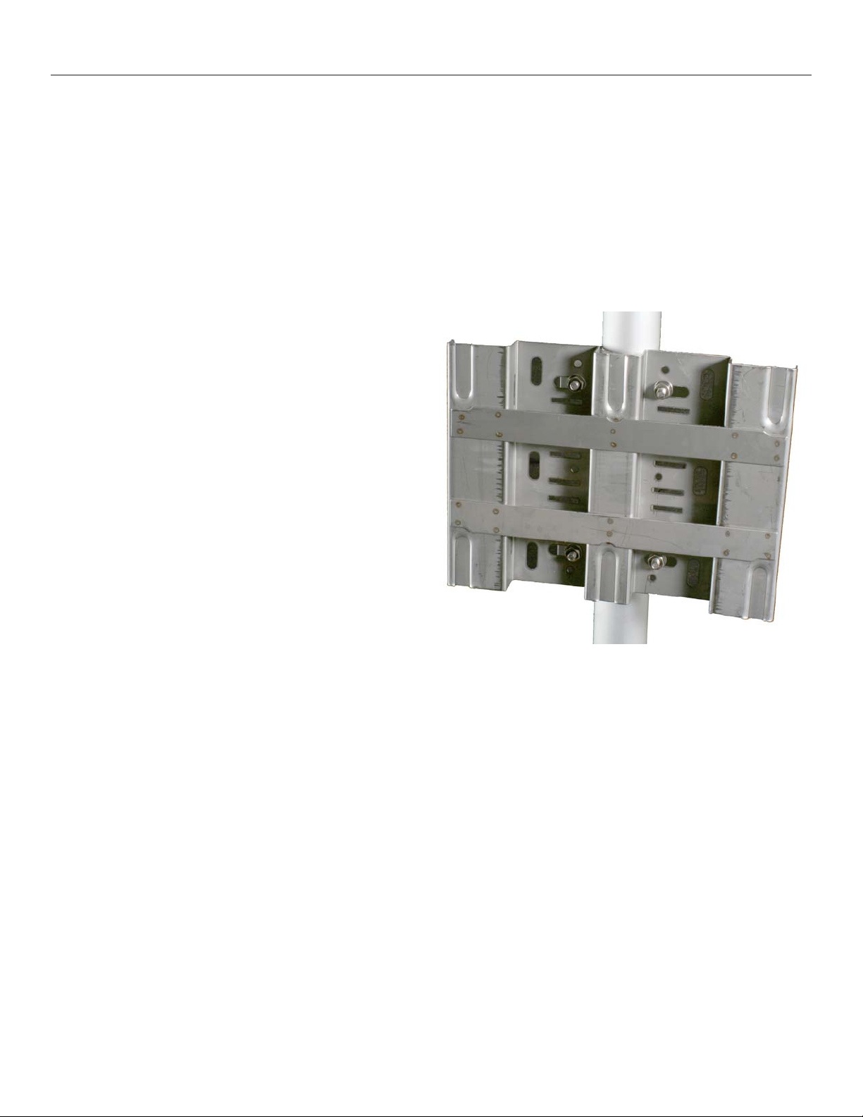
The Universal Mounting Bracket, shown in Figure 5, contains
1.
holes and slots to allow it to be mounted via U-bolts or straps.
Furthermore, it can be mounted on either a horizontal pole or a
vertical pole. Use four screws to attach the universal mounting
bracket securely to the wall using the four holes near the top
and bottom of the universal mounting bracket. Use appropriate
anchors when attaching to masonry or other materials.
Attach the enclosure to the universal mounting bracket by slid-
2.
ing the metal clips on the back of the enclosure into the metal
straps on the universal mounting bracket.
Secure the enclosure to the universal mounting bracket using
3.
the four captive screws on the sides on the universal mounting
bracket.
Pole Mounting
You can mount the HotPort node to a pole using U-bolts. The section below describes how to mount the enclosure to a 1.5” (37 mm)
or 2” (50 mm) pole.Position the pole mounting bracket against the
pole. Insert the U-bolts from behind the pole and through the pole
mounting bracket.
You installation kit includes a small T-handle socket wrench which
fits the supplied nuts.
Insert the two U-bolts through the four holes near the top and
1.
bottom of the universal mounting bracket.
On each U-bolt threaded shaft, place a washer, a lock washer,
2.
and one or more 6 mm nuts as spacers. Smaller pole diameters
usually require a spacer nut to hold the bracket away from the
U-bolt clamp.
Use four lock washers and 6 mm nuts to secure the universal
3.
mounting bracket, pole mounting bracket, and U-bolts assembly.
4.
ing the metal clips on the back of the enclosure into the metal
straps on the universal mounting bracket.
Secure the enclosure to the universal mounting bracket using
5.
the four captive screws on the sides of the universal mounting
bracket.
Figure 5. Universal Mounting Bracket Attached to Pole
Using Mounting Straps
For poles with diameters larger than 2” (50 mm), horizontal poles,
irregularly shaped poles, or lighting lamps, you can use mounting straps to mount the HotPort enclosure. Position the universal
mounting bracket against the pole.
Thread two mounting straps around the pole and through the
1.
slots located near the top and bottom of the universal mounting bracket. Secure the mounting straps.
Attach the enclosure to the universal mounting bracket by slid-
2.
ing the metal clips on the back of the enclosure into the metal
straps on the universal mounting bracket.
Secure the enclosure to the universal mounting bracket using the
four captive screws on the sides of the universal mounting bracket.
10 HotPort 6000 Series Mesh Nodes February 2007
Page 11
Mounting the Node
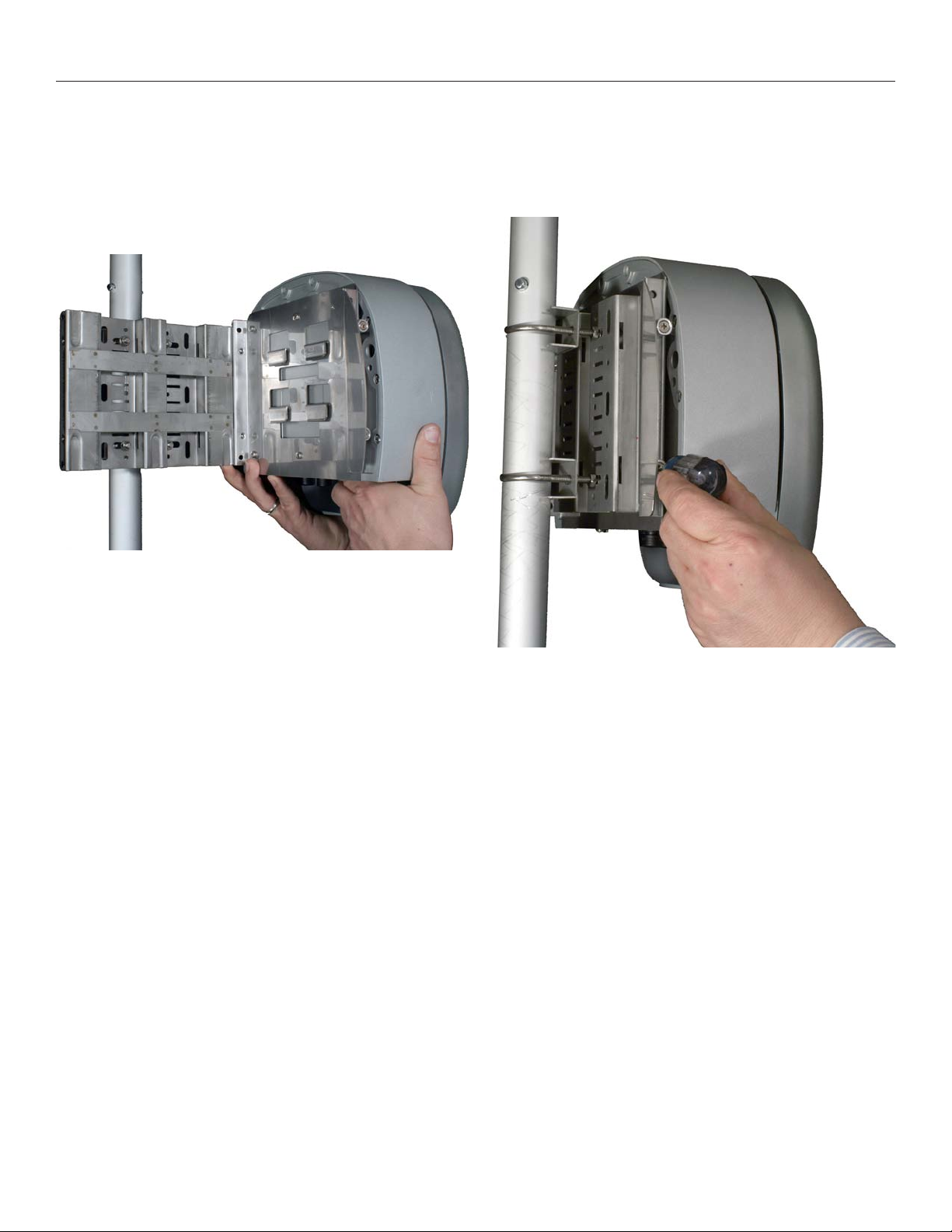
Attach the supplied backing plate to the HotPort node, using the
supplied screws. Note that the holes in the node are pre-tapped for
the supplied metric screws; do not use other screws.
Next, slide the node assembly onto the bracket, so that the four tabs
on the node assembly engage the straps on the bracket, as shown
in the photo.
Figure 6. Mounting the Node
Then tighten the four captive screws on the node assembly. This
locks the node onto the bracket. Don’t leave these screws loose; if
you do, it’s easy to knock the node off the bracket.
Figure 7. Tighten Screws
Firetide Instant Mesh Networks 11 February 2007
Page 12
Connecting Cables
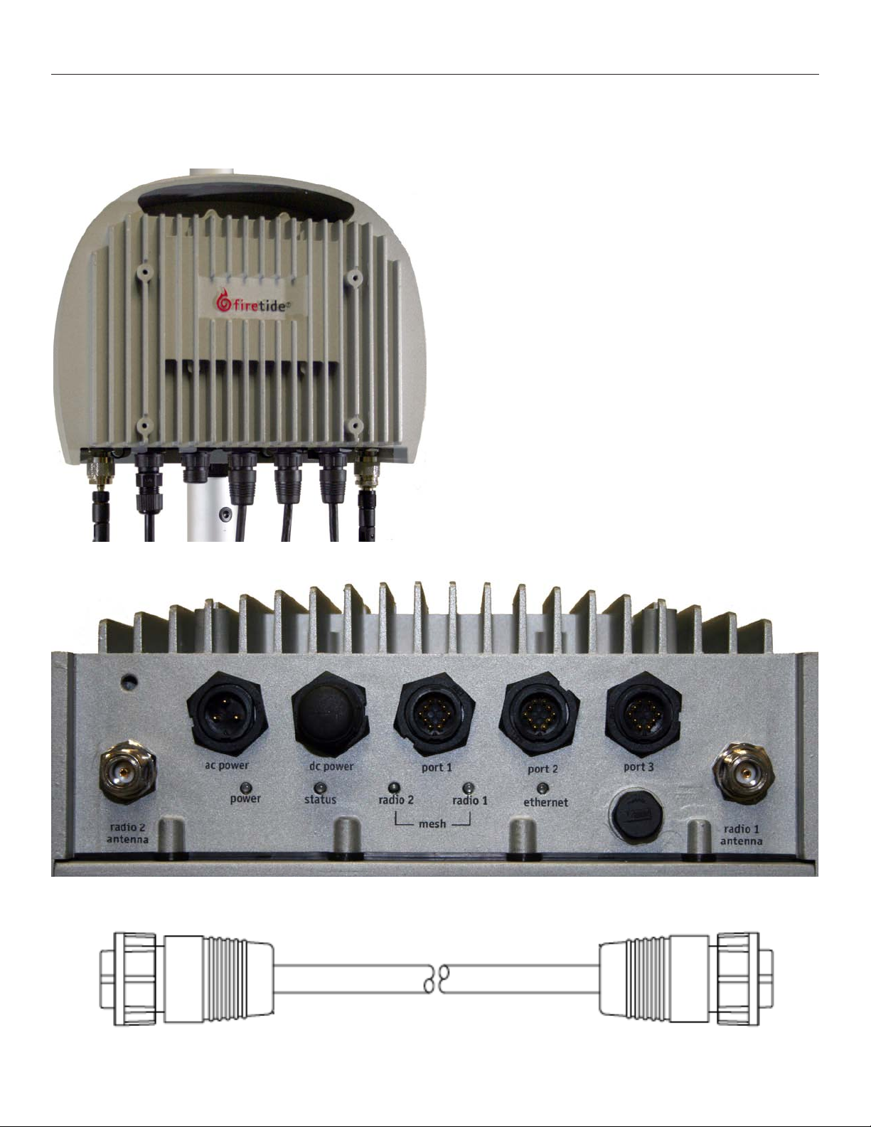
After your node is securely mounted, attach the two antennas, the
power cable, and any Ethernet cables you need, as shown in Figures
8 and 9.
Figure 8. Connected Outdoor Node
If you are using your Series 6200 with a companion Firetide HotPoint access point, a special Ethernet cable is available to connect
the two units and to supply PoE power to the AP. The cable is shown
in Figure 10.
Note the locations of the reset button under the weatherproof cap,
just below Ethernet port 3. To perform a factory reset on the unit,
power it on and wait for the status light to come on. Then press the
reset button.
Figure 9. HotPort Node Bottom Panel
Figure 10. Ethernet Cable for HotPort-HotPoint AP Connection
12 HotPort 6000 Series Mesh Nodes February 2007
Page 13
Power Options - Outdoor Nodes
Power Supply
The power supply can provide power to the HotPort enclosure from
an AC outlet. The power supply is rated for 90-240 VAC.
Powering Other Ethernet Devices
Ports 2 and 3 on a 6200 Series node can provide Power over Ethernet (PoE) functionality to Powered Devices (PD) connected to these
ports. (Port 1 cannot.) A Powered Device can receive data and the
power to process the data from the HotPort node, which functions
as Power Sourcing Equipment (PSE) in this configuration. To receive power from a HotPort node, the device must support the IEEE
802.3af standard, which defines PoE functionality.
Building a Custom Ethernet Cable
Firetide supplies a cable that will connect your 6200 Series node
directly to a HotPoint Access Point. To connect to other devices, you
will need to assemble an adapter cable. To assist in this, Firetide
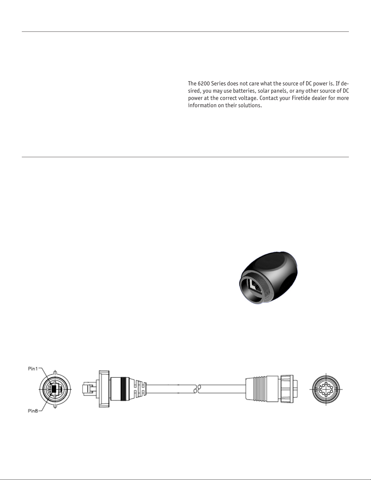
supplies a weatherized Ethernet transition cable, which is PoE compatible. A weatherized RJ-45 coupler is also included.
To connect power to the unit from PSE:
Construct a shielded Category 5 Ethernet cable:
1.
Insert one end of the Ethernet cable (without an RJ-45 connec-
2.
tor) through the provided coupler housing.
Use an RJ-45 crimping tool to attach an RJ-45 connector to this
3.
end of the Ethernet cable.
Insert the male RJ-45 connector on the constructed Ethernet
4.
cable into the female-to-female Ethernet coupler.
Connect the male RJ-45 connector on the Firetide-supplied
5.
Ethernet transition cable to the female-to-female coupler.
Remove the protective cap from an Ethernet port on the Hot-
6.
Port enclosure and insert the circular, 10-pin connector on the
Ethernet transition cable.
Tighten all connectors to ensure a watertight seal.
7.
DC Power
In addition to its AC input, the 6200 Series features a DC input. It
is compatible with older 3200 Series external power supplies, so if
you are upgrading an older node, you may re-use the supply if convenient.
The 6200 Series does not care what the source of DC power is. If de-
sired, you may use batteries, solar panels, or any other source of DC
power at the correct voltage. Contact your Firetide dealer for more
information on their solutions.
Do not connect both AC and DC supplies simultaneously.
Note: Regardless of your exact configuration of Ethernet cable and
power sources, you must make sure all cables and connections are
completely waterproofed. It is a good installation practice to leave
enough cable slack so that there is a drip loop in each cable. This provides a low point for water to drip off the cable, rather that running
down to a connector.
Figure 11.
Waterproof RJ-45 Coupler
Figure 12. Waterproof Ethernet Cable
Firetide Instant Mesh Networks 13 February 2007
Page 14

Appendix A - Contacting Firetide
Dealer Provided Technical Support and Warranty Services
If you need additional technical assistance, please contact your
Firetide dealer directly. All authorized Firetide dealers are trained
and authorized to provide technical support and warranty services
for our products and have qualified technical staff available to help
you build and maintain your Firetide mesh network.
Firetide Provided Technical Support
You can also get technical support from Firetide. Simply email support@firetide.com, or call 1-877-FIRETIDE, extension 2, or +1 408
399 7771.
Product Returns
Please contact your Firetide dealer for instructions on returning
defective or damaged products for repair or replacement. Do not
return products to Firetide, Inc. Please keep all original packaging
materials in the event they are needed to return the product for servicing.
Sales Assistance
If you need additional HotPort wireless mesh nodes or accessories,
please contact your Firetide dealer directly. If you do not know your
dealer’s name, simply email sales@firetide.com and we will send
you the dealer information you need. To help us provide the best
service possible, be sure to include your phone number, address,
and the serial numbers of the HotPort nodes at your location.
14 HotPort 6000 Series Mesh Nodes February 2007
Page 15
Appendix B - Connector Wiring
9 10
7 8
5 6
3 4
1 2
brown
blue
black
white
power
ground/drain
Pin 1
Pin 2
Pin 3
Pin 4
Pin 3
Pin 4
1
2
3
4
5
6
1
2
3
4
Female - End View
Connect to 6200
Series HotPort
Male - End View
Connect to Power
Supply
HotPort Outdoor Node Ethernet Transition Cable Pin Descriptions
Table 2. Circular, Watertight IP66-Rated Connector and Port Pin Descriptions
Connector Pin # Wire Color Port Pin #
1 White/Orange 1
2 Orange 2
3 White/Green 3
4 Blue 4
5 White/Blue 5
6 Green 6
7 White/Brown 7
8 Brown 8
Drain Wire 9
Drain Wire 10
Table 3. RJ-45 Connector Pin Descriptions
Pin # Signal Description
1 TXD+ TX Data 10 BaseT/100 BaseTX
2 TXD- TX Data 10 BaseT/100 BaseTX
3 RXD+ RX Data 10 BaseT/100 BaseTX
4 PoE+ +48 VDC PoE Power
5 PoE+ +48 VDC PoE Power
Power Connector Pin Descriptions
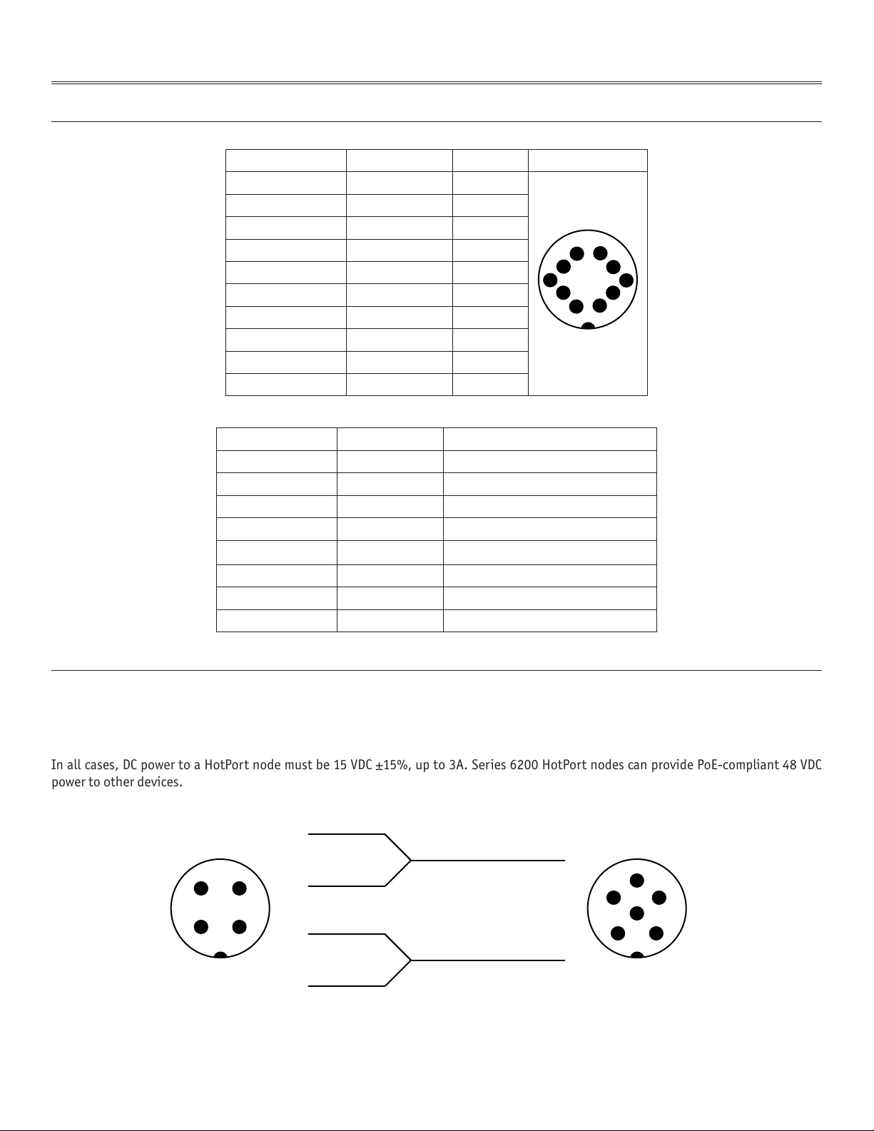
Figure 13 shows the pinout of the power connectors used to supply power to Series 6100 nodes (left) and Series 6200 nodes (right). Each
view is of the cable connector, as viewed end-on.
If you wish to construct a cable to supply power to a Series 6200 node with a Series 6100 node indoor power supply, you can do so by wiring
as shown in Figure 13. Likewise, other cables can be constructed for custom applications, as long as the wiring shown is followed.
In all cases, DC power to a HotPort node must be 15 VDC ±15%, up to 3A. Series 6200 HotPort nodes can provide PoE-compliant 48 VDC
power to other devices.
6 RXD- RX Data 10 BaseT/100BaseTX
7 PoE- -48 VDC PoE Power
8 PoE- -48 VDC PoE Power
Figure 13. Power Transition Cable
Firetide Instant Mesh Networks 15 February 2007
Page 16
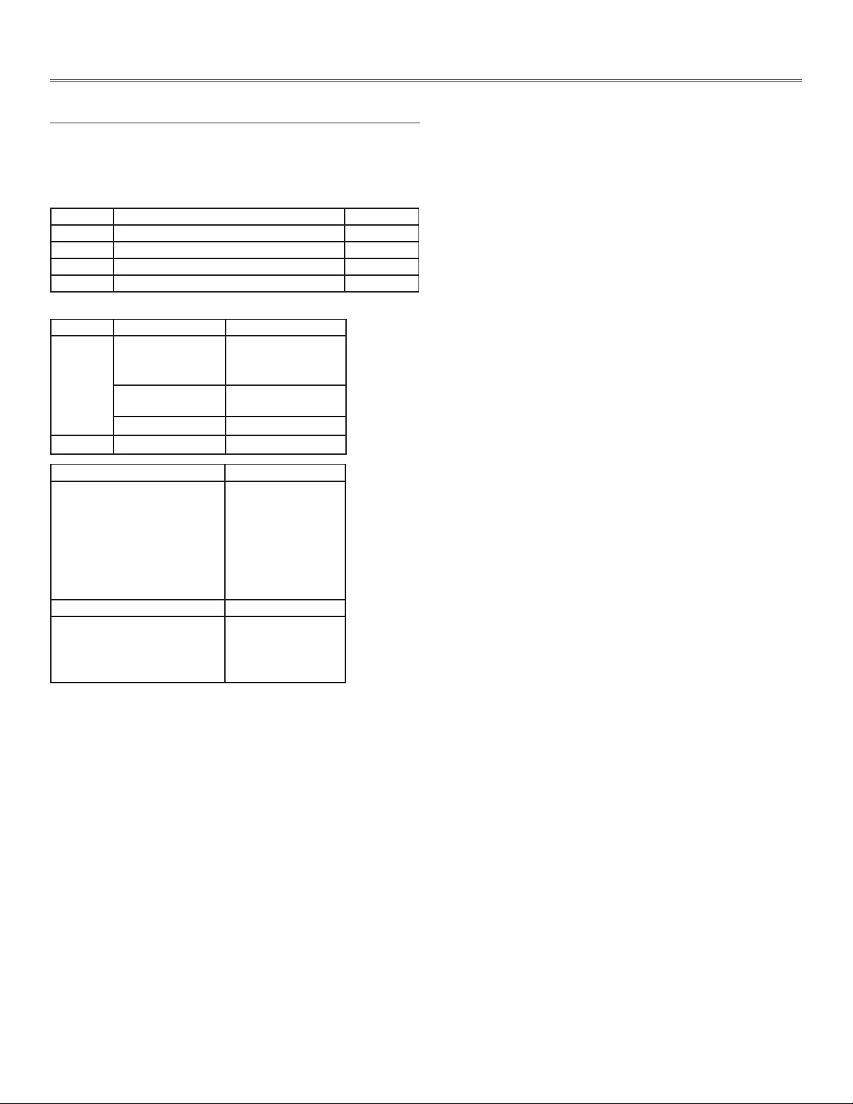
Appendix C - Specifications
Common Specifications
Wireless Interface
These tables describes the technical limits of the nodes. Various
country restrictions may further limit available choices.
Model Use No. of Radios
6101 Indoor, Worldwide, 2.4, 4.9, 5 GHz 1
6102 Indoor, Worldwide, 2.4, 4.9, 5 GHz 2
6201 Outdoor, Worldwide, 2.4, 4.9, 5 GHz 1
6202 Outdoor, Worldwide, 2.4, 4.9, 5 GHz 2
For all models:
Bands (GHz) Frequency (GHz) Restrictions
802.11a 5.15-5.25
5.25-5.35
5.725-5.825
4.9-5.090
4.94-4.990
5.470-5.725 ETSI 301.893, U-NII
802.11b/g 2.412-2.484
Bands (GHz) Max TX Power
802.11a 5.725-5.825 UNII-3
5.470-5.735 UNII
5.25-5.36 M UNII-2
5.15-5.25 UNII-1
802.11b 24 dBm/all rates
802.11g 26dBm/6-24Mbps
Japan only
US Public Safety
26dBm/6-24Mbps
26dBm/36Mbps
24dBm/48Mbps
23dBm/54Mbps
23 dBm 6-54 Mbps
23 dBm 6-54 Mbps
17 dBm 6-54 Mbps
26dBm/36Mbps
25dBm/48Mbps
24dBm/54Mbps
Supported Data Rates & Standards
802.11a 6/9/12/18/24/36/48/54Mbps + 108Mbps (Turbo
•
Mode) except Japan
802.11a Capable of switching to 1⁄4 and 1⁄2 rates for 4.940
•
– 4.990 GHz Public Safety Band
802.11b 1/2/5.5/11Mbps
•
802.11g 6/9/12/18/24/36/48/54Mbps
•
Network Standards: IEEE 802.11a/b/d/g/e/f/h/i
•
Dynamic Frequency Selection (DFS) capable in conjunction with
•
Firetide Software application
Transmit Power Control (TPC) capable in conjunction with Firetide
•
Software application
Mesh Protocol
Firetide AutoMesh Protocol
•
Mesh Management Software
HotView mesh management software (bundled)
•
HotView Pro™ mesh management software (optional)
•
Security & Encryption
Security: WPA—64/128/152 w/TKIP, AES, IEEE 802.1x (LEAP)
•
Antennas
Two detachable omni directional, vertical polarization, dual
•
band antennas
Single detachable, high gain, spectrum-specific, omni direc-
•
tional and directional antennas available (order separately). See
Firetide Antenna Guide.
Regulatory Agency Certifications
Contact your Firetide dealer for product availability and certifi-
•
cations for your country.
16 HotPort 6000 Series Mesh Nodes February 2007
Page 17

Outdoor Unit Specifications
Indoor Unit Specifications
Network Ports
Three 10/100 Mbps Ethernet ports with weatherproof connec-
•
tors, LED activity indicator
IEEE 802.3, 802.3u compliant
•
CSMA/CD 10/100 autosense
•
Ports 2, 3 PSE Power over Ethernet per 802.3af
•
Enclosure
Cast aluminum NEMA-4X/IP66 enclosure
•
Two N-type antenna connectors
•
Two weatherproof power connectors (AC and DC)
•
Three weatherproof Ethernet connectors
•
System indicator LEDs (power, status, mesh (per radio))
•
Weight: 12 lbs (5.5 Kg) with bracket
•
Dimensions: 8.8” x 11.2” x 4” (220 x 280 x 100 mm)
•
Power
AC Input: 90-240 VAC, 50-60 Hz, 0.9A
•
DC Input: 15 VDC ±15%, 3 A
•
Port 2: IEEE 802.3af compliant PoE (PSE), 13.5 W max
•
Port 3: IEEE 802.3af compliant PoE (PSE), 13.5 W max
•
Environmental Specifications
Operating temperature: -40º C to +60ºC
•
Storage temperature: -40º C to +85º C
•
Humidity (non-condensing): 10% to 90%
•
Storage humidity (non-condensing): 5% to 95%
•
Maximum altitude 15,000 feet (4600 meters)
•
Included Accessories
Bracket for pole and wall mounting
•
External power cord
•
Removable sun shield
•
One weatherized Ethernet transition cable with watertight RJ-
•
45 coupling. Additional cable kits may be ordered.
Staging antennas, 1 pair
•
Network Ports
Four 10/100 Mbps Ethernet ports with LEDs
•
IEEE 802.3, 802.3u compliant
•
CSMA/CD 10/100 autosense
•
Enclosure
Plenum-rated metal enclosure
•
Two RP-SMA antenna connectors
•
One DC power connector
•
Four Ethernet connectors
•
System indicator LEDs: power, status, per-radio mesh
•
Weight: 3 lbs (1.4 Kg)
•
Dimensions: 9.4” x 6” x 1.8” (238 x 152 x 48 mm)
•
Power
DC Input: 15 VDC ±15%, 3 A
•
Environmental Specifications
Operating temperature: 0º C to +60ºC
•
Storage temperature: -20º C to +70º C
•
Humidity (non-condensing): 10% to 90%
•
Storage humidity (non-condensing): 5% to 95%
•
Maximum altitude 15,000 feet (4600 meters)
•
Included Accessories
AC power adapter
•
Staging antennas, 1 pair
•
Optional Accessories
Wall or cubicle-mount bracket
•
Optional Accessories
Outdoor weatherproof Ethernet cable for use with HotPoint APs
•
Luminaire photocell socket power tap
•
Firetide Instant Mesh Networks 17 February 2007
Page 18

Appendix D - Regulatory Notices
USA
FCC Class A Notice
This device complies with Part 15 of the FCC Rules. Operation is subject to the following two conditions:
This device may not cause harmful interference.
•
This device must accept any interference received, including in-
•
terference that may cause undesired operation.
FCC Part 15 Note
This equipment has been tested and found to comply with the limits
for a Class A digital device, pursuant to Part 15 of the FCC Rules.
These limits are designed to provide reasonable protection against
harmful interference in an office installation. This equipment generates, uses and can radiate radio frequency energy and, if not
installed and used in accordance with the instructions, may cause
harmful interference to radio communications. However, there is no
guarantee that interference will not occur in a particular installation. If this equipment does cause harmful interference to radio or
television reception, which can be determined by turning the equipment off and on, the user is encouraged to try to correct the interference by one or more of the following measures:
Reorient or relocate the receiving antenna.
•
Increase the separation between the equipment and receiver.
•
Connect the equipment into an outlet on a circuit different from
•
that to which the receiver is connected.
Consult the dealer or an experienced radio/television technician
•
for help.
FCC Part 90 Note
This equipment has been tested pursuant to FCC Part 90, DSRC-C
mask certification, and is approved for use in the US on Public Safety
bands by licensed Public Safety agencies.
FCC Radiation Exposure Statement
To ensure compliance with the FCC’s RF exposure limits, the antenna
used for this transmitter must be installed to provide a separation
distance of at least 90 cm from all persons and must not be co-located or operated in conjunction with any other antenna or transmitter. Installers and end users must follow these installation instructions.
Installation
Antenna(s) for this unit must be installed by a qualified professional. Operation of the unit with non- approved antennas is a violation
of U. S. FCC Rules, Part 15.203(c), Code of Federal Regulations, Title
47.
Canadian Compliance Statement
This Class A Digital apparatus meets all the requirements of the Canadian Interference-Causing Equipment Regulations. Cet appareil
numerique de la classe A respecte les exigences du Reglement sur
le material broilleur du Canada. This device complies with Class A
Limits of Industry Canada. Operation is subject to the following two
conditions:
1. This device may not cause harmful interference, and
2. This device must accept any interference received, including interference that may cause undesired operation.
Firetide HotPoint 6100 and 6200 wireless mesh nodes are certified
to the requirements of RSS-210 for 2.4 and 5 GHz spread spectrum
devices. The use of this device in a system operating either partially
or completely outdoors may require the user to obtain a license for
the system according to the Canadian regulations. For further information, contact your local Industry Canada office.
Public Safety Band
Pursuant to Part 90.1215, use of antennas with gain greater than 9
dBi and up to 26 dBi in the 4.940 - 4.990 GHz Public Safety band is
permissible without reduction of TX output power. The antenna shall
have a directional gain pattern in order to meet the requirement of
point to point and point to multi-point operation.
Modifications
Any modifications made to this device that are not approved by
Firetide, Inc. may void the authority granted to the user by the FCC
to operate this equipment.
18 HotPort 6000 Series Mesh Nodes February 2007
Page 19

Firetide Instant Mesh Networks 19 February 2007
Page 20

 Loading...