

Page 1
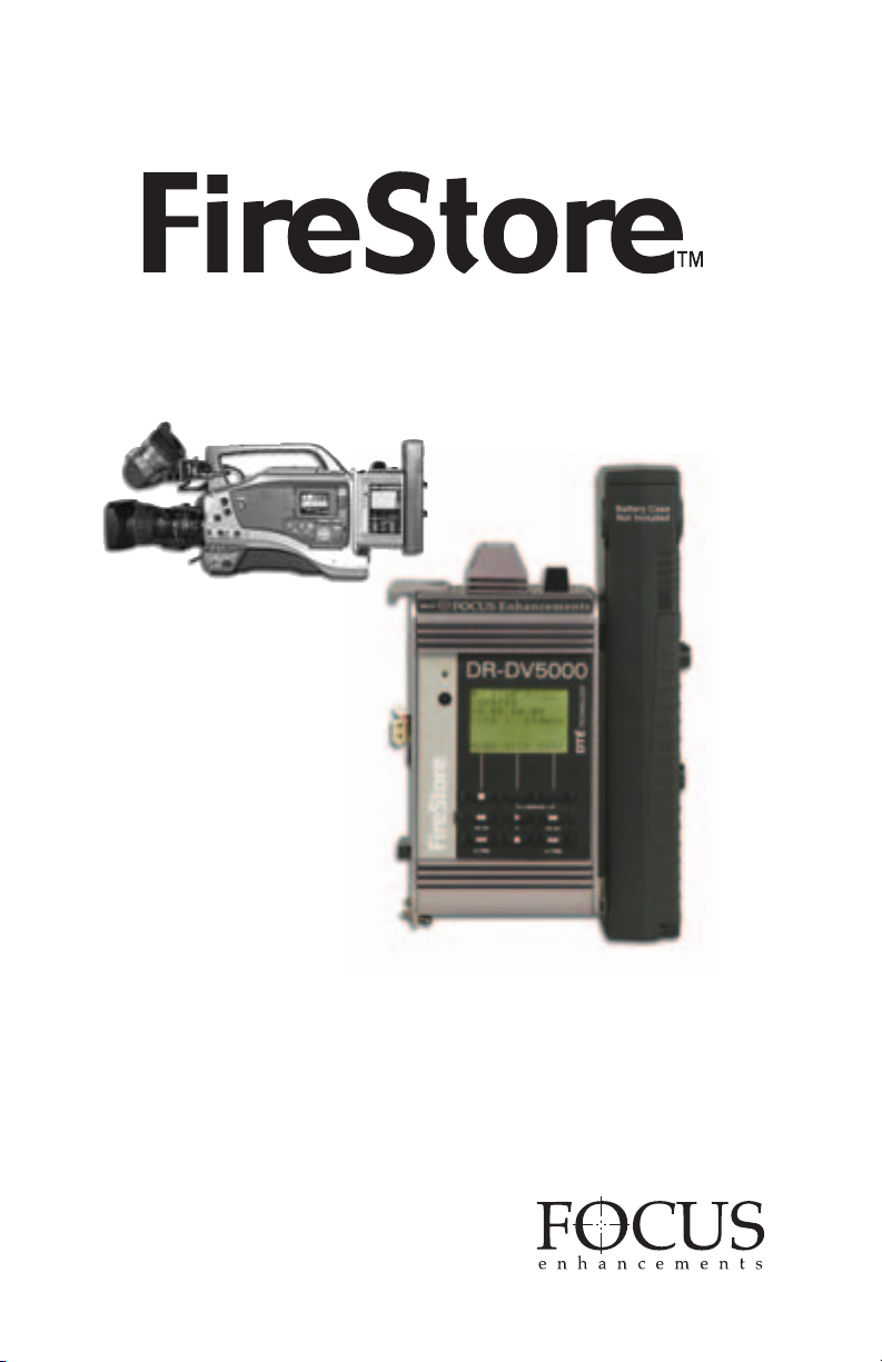
DV Video Disk Recorder
DR-DV5000
USER GUIDE
Version 1.2
Page 2
FireStore DR-DV5000 User Guide
FireStore DR-DV5000 User Guide
WARNING: TO PREVENT FIRE OR
SHOCK HAZARD, DO NOT EXPOSE
THIS EQUIPMENT TO RAIN OR
MOISTURE.
IMPORTANT NOTICE
(For U.S.Model)
The serial number for this equipment is located
on the bottom of the unit. Please write this serial
number on your enclosed warranty card and
keep it in a secure area. This is for your security.
CAUTION:
This product satisfies FCC regulations when
shielded cables and connectors are used to
connect the unit to other equipment. To prevent
electromagnetic interference with electric
appliances such as radios and televisions, use
shielded cables and connectors for connections.
NOTE:
This equipment has been tested and found
to comply with the limits for a Class A
digital device, pursuant to Part 15 of the
FCC Rules. These limits are designed to
provide reasonable protection against harmful
interference in a residential installation.
This equipment generates, uses, and can
radiate radio frequency energy and, if not
installed and used in accordance with the
instructions, may cause harmful interference
to radio communications. However, there is
no guarantee that interference will not
occur in a particular installation. If this
equipment does cause harmful interference
to radio or television reception,which can
be determined by turning the equipment off
and on, the user is encouraged to try to
correct the interference by one or more
of the following measures:
• Reorient or relocate the receiving
antenna.
• Increase the separation between the
equipment and receiver.
• Connect the equipment into an outlet
on a circuit different from that to
which the receiver is connected.
• Consult the dealer or an experienced
radio/TV technician for help.
INFORMATION TO USER
Alteration or modifications carried out
without appropriate authorization may
invalidate the user’s right to operate
the equipment.
CAUTION:
• Use of controls or adjustments or
performance of procedures other than
those specified herein may result in
hazardous radiation exposure.
• The use of optical instruments with
this product will increase eye hazard.
THE ON/OFF SWITCH IS SECONDARY
CONNECTED AND THEREFORE DOES
NOT SEPARATE THE UNIT FROM
MAINS POWER IN STANDBY
POSITION.
CAUTION:TO PREVENT ELECTRIC
SHOCK, DO NOT USE A (POLARIZED)
PLUG WITH AN EXTENSION CORD,
RECEPTACLE OR OTHER OUTLET
UNLESS THE BLADES CAN BE FULLY
INSERTED TO PREVENT BLADE
EXPOSURE.
ATTENTION: POUR PREVENIR LES
CHOCS ELECTRIQUES NE PAS
UTILISER CETTE FICHE POLARISEE
AVEC UN PROLONGATEUR, UNE PRISE
DE COURANT OU UNE AUTRE SORTIE
DE COURANT, SAUF SI LES LAMES
PEUVENT ETRE INSEREES A FOND
SANS EN LAISSER
DECOUVER
AUCUNE PARTIE A
T.
Please read through these operating instructions so you will know how to operate your model
properly. After you have finished reading the instructions, put them away in a safe place for
future reference.
PAGE 1
Page 3
FireStore DR-DV5000 User Guide
ELECTRIC
SERVICE
EQUIPMENT
GROUND
CLAMP
ANTENNA
LEAD IN WIRE
ANTENNA
DISCHARGE UNIT
(NEC SECTION 810-20)
GROUNDING CONDUCTORS
(NEC SECTION 810-21)
NEC — NATIONAL ELECTRICAL CODE
GROUND CLAMPS
POWER SERVICE GROUNDING
ELECTRODE SYSTEM
(NEC ART 250. PART H)
Fig A
IMPORTANT
CAUTION
RISK OF ELECTRIC SHOCK
DO NOT OPEN
READ INSTRUCTIONS – All the safety and
operating instructions should be read before the
product is operated.
RETAIN INSTRUCTIONS – The safety and
operating instructions should be r
future reference.
HEED WARNINGS – All warnings on the product
and in the operating instr
adhered to.
FOLLOW INSTRUCTIONS – All operating and use
instructions should be followed.
CLEANING – Unplug this product from the wall
outlet before cleaning. The product should be
cleaned only with a polishing cloth or a soft dry
cloth. Never clean with furniture wax, benzine,
insecticides or other volatile liquids since they
may corrode the cabinet.
ATTACHMENTS – Do not use attachments not
recommended by the product manufacturer as
they may cause hazards.
WATER AND MOISTURE – Do not use this
product near water – for example, near a bathtub,
wash bowl, kitchen sink, or laundry tub; in a wet
basement; or near a swimming pool; and the like.
ACCESSORIES – Do not place this product on an
unstable cart, stand, tripod, bracket or table. The
product may fall, causing serious injury to a child
or an adult, and serious damage to the product.
Use only with a cart, stand, tripod, bracket or
table recommended by the manufacturer, or sold
with the product. Any mounting of the product
should follow the manufacturer’s instructions, and
should use a mounting accessory recommended
by the manufacturer.
CART – A product and cart combination should be
moved with care. Quick stops, excessive force,
and uneven surfaces may cause the product and
cart combination to overturn.
VENTILATION – Slots and openings in the cabinet
are provided for ventilation and to ensure reliable
operation of the product and to protect it from
overheating, and these openings must not be
blocked or covered. The openings should never be
blocked by placing the product on a bed, sofa, rug,
or other similar surface. This product should not be
placed in a built-in installation such as a bookcase
or rack unless proper ventilation is provided or the
manufacturer’s instructions have been adhered to.
POWER SOURCES – This product should be
operated only form the type of power source
indicated on the marking label. If you ar
the type of power supply to your home, consult
your dealer or local power company.
uctions should be
etained for
e not sure of
CAUTION:
TO PREVENT THE RISK OF
ELECTRIC SHOCK, DO NOT
REMOVE COVER (OR BACK).
NO USER SERVICEABLE PARTS
INSIDE.REFER SERVICING TO
QUALIFIED SERVICE PERSONNEL.
IMPORTANT SAFETY INSTRUCTIONS
LOCA
– The appliance should be installed in
TION
a stable location.
NON-USE PERIODS – The power cord of the
appliance should be unplugged from the outlet
when left unused for a long period of time.
GROUNDING OR
• If this product is equipped with a polarized
alter
blade wider than the other), it will fit into the
outlet only one way. This is a safety feature. If
you are unable to insert the plug fully into the
outlet, try reversing the plug. If the plug should
still fail to fit, contact your electrician to replace
your obsolete outlet. Do not defeat the safety
purpose of the polarized plug.
• If this product is equipped with a three-wire
grounding type plug, a plug having a third
(grounding) pin, it will only fit into a grounding
type power outlet. This is a safety feature. If you
are unable to insert the plug into the outlet,
contact your electrician to replace your obsolete
outlet. Do not defeat the safety purpose of the
grounding type plug.
POWER-CORD PROTECTION – Power supply cords
should be routed so that they are not likely to be
walked on or pinched by items placed upon or
against them, paying particular attention to cords at
plugs, convenience receptacles, and the point where
they exit the product.
OUTDOOR ANTENNA GROUNDING – If an outside
antenna or cable system is connected to the
product, be sure the antenna or cable system is
grounded so as to provide some protection against
voltage surges and built-up static charges. Article
810 of the National Electric Code, ANSI/NFP
provides information with regard to proper
grounding of the mast and supporting structure,
grounding of the lead-in wire to an antenna
discharge unit, size of grounding connectors,
location of antenna dischar
grounding electrodes, and requirements for the
grounding electrode. See Fig. A.
LIGHTNING – For added protection for this product
during a lightning storm, or when it is left unattended
and unused for long periods of time, unplug it fr
the wall outlet and disconnect the antenna or cable
system. This will prevent damage to the product due
to lightning and power-line surges.
POWER LINES – An outside antenna system
should not be located in the vicinity of overhead
power lines or other electric light or power
circuits, or where it can fall into such power lines
or circuits. When installing an outside antenna
system, extreme care should be taken to keep
from touching such power lines or circuits as
contact with them might be fatal.
OVERLOADING – Do not overload wall outlets,
extension cords, or integral convenience
receptacles as this can result in a risk of fire or
electric shock.
POLARIZATION –
nating current line plug ( a plug having one
A 70,
ge unit, connection to
om
The exclamation point within an
equilateral triangle is intended to alert
the user to the presence of important
operating and maintenance (servicing)
instructions in the literature accompanying
the appliance.
OBJECT AND LIQUID ENTRY – Never push
objects of any kind into this product through
openings as they may touch dangerous voltage
points or short-out parts that could result in a fire
or electric shock. Never spill liquid of any kind on
the product.
SERVICING – Do not attempt to service this
product yourself as opening or removing covers
may expose you to danger
hazards. Refer all servicing to qualified service
personnel.
DAMAGE REQUIRING SERVICE – Unplug this
product from the wall outlet and refer servicing to
qualified service personnel under the following
conditions:
• When the power-supply cord or plug is damaged.
• If liquid has been spilled, or objects have fallen
into the product.
• If the product has been exposed to rain or water.
• If the product does not operate normally by
following the operating instructions. Adjust
only those controls that are covered by the
operating instructions as an improper
adjustment of other controls may result in
damage and will often require extensive work
by a qualified technician to restore the product
to its normal operation.
• If the product has been dropped or damaged in
any way.
• When the product exhibits a distinct change in
performance – this indicates a need for service.
REPLACEMENT PARTS – When replacement parts
are required, be sure the service technician has
used replacement parts specified by the
manufacturer or have the same characteristics as
the original part. Unauthorized substitutions may
result in fire, electric shock or other hazards.
SAFETY CHECK – Upon completion of any service
or repairs to this product, ask the service
technician to perform safety checks to determine
that the product is in proper operating condition.
WALL OR CEILING MOUNT – The product should
not be mounted to a wall or ceiling.
HEAT – The product should be situated away from
heat sources such as radiators, heat, registers,
stoves or other products (including amplifiers)
that produce heat.
ous voltage or other
Page 4
FireStore DR-DV5000 User Guide
PAGE 3
Page 5

FireStore DR-DV5000 User Guide
FOCUS Enhancements, Inc. warrants
this product against defects in materials
or workmanship as follows:
For a period of TWO years from the date
of purchase, FOCUS Enhancements, Inc.
will repair or replace the unit, at our option,
without charge for parts or labor. After the
period of TWO years, you must pay all
parts and labor charges.
The limited warranty is extended only to
the original purchaser. It does not cover damage
or failure caused by or attributable
to Acts of God, abuse, misuse, improper or
abnormal usage, faulty installation, improper
maintenance, lightning, or other incidences of
excessive voltage, or any repairs or tampering
by other than a FOCUS Enhancements
authorized repair facility. It does not cover
replacement of batteries or other consumable
parts, transportation costs or damage in transit.
This warranty will become void if the serial
number or model number identification has
been wholly or partially removed or erased.
Repair or replacement under the
ms of this warranty do not extend the
ter
terms of this warranty. This warranty can
not be modified by an agent of FOCUS
Enhancements, Inc. unless in written and signed
by an officer of FOCUS Enhancements, Inc.
Should this product prove defective in
workmanship or material, the consumer’s
sole remedies shall be such repair or
replacement provided by the terms of
this warranty. Under no circumstances shall
FOCUS Enhancements, Inc. be liab
y loss or damage, direct, consequential, or
an
le for
incidental, arising out of the use of or inability
to use this product. Some states do not allow
limitations on how long an implied warranty
lasts or the exclusions or limitations of
incidental or consequential damages, so the
above limitations or exclusions may not apply
to you. This warranty gives you specific legal
rights. You may also have other rights which
vary from state to state.
For customers outside the USA or Canada,
please contact your dealer or distributor
for repairs or technical support. Refer to
document MANL-0907-XX for a list of
International Dealers and Authorized
Service Centers.
In the United States or Canada, to obtain
warranty service, call or write the FOCUS
Enhancements, Inc. Technical Support Line
for a Return Material Authorization (RMA)
number. Technical Support can be reached at:
Email: support@FOCUSinfo. com
Telephone: 408-370-9963. 8AM-5PM,
Monday to Friday (PST)
(Hint: Mondays tend to be the
busiest)
Fax: 408-866-4859
Address: FOCUS Enhancements, Inc.
1370 Dell Ave.
Campbell, CA. 95008
Please mark the RMA number clearl
the outside of the package. Include a cop
y on
y
of your sales receipt, a brief description of
the symptoms, your name, address, phone
number and any special shipping instructions.
Then deliver or ship the product, postage
and shipping costs prepaid, to a FOCUS
Enhancements authorized repair facility. For
the name of the nearest repair facility, contact
FOCUS Enhancements, Inc. Technical Support.
PAGE 4
Page 6
FireStore DR-DV5000 User Guide
Table of Contents . . . . . . . . . . . . . . . . . . . . . . . . . . . . . . . . . . . . . . . . . . . . . . . . . . . .PAGE
Warning and Safety Information . . . . . . . . . . . . . . . . . . . . . . . . . . . . . . . . . . . . . . . . . . . . . . . . . . . . .1
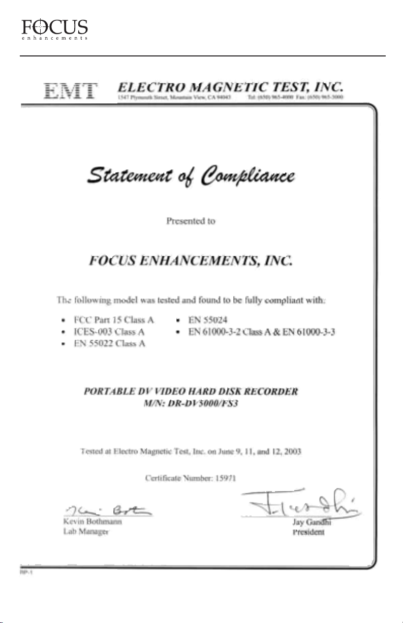
Statement of Compliance . . . . . . . . . . . . . . . . . . . . . . . . . . . . . . . . . . . . . . . . . . . . . . . . . . . . . . . . . .3
Statement of Warranty . . . . . . . . . . . . . . . . . . . . . . . . . . . . . . . . . . . . . . . . . . . . . . . . . . . . . . . . . . . . .4
Introduction . . . . . . . . . . . . . . . . . . . . . . . . . . . . . . . . . . . . . . . . . . . . . . . . . . . . . . . . . . . .7
PACKAGE CONTENTS . . . . . . . . . . . . . . . . . . . . . . . . . . . . . . . . . . . . . . . . . . . . . . . . . . . . . . . . . . .7
WHAT IS A DTE DISK RECORDER? . . . . . . . . . . . . . . . . . . . . . . . . . . . . . . . . . . . . . . . . . . . . . . .7
WHAT IS FIRESTORE DR-DV5000? . . . . . . . . . . . . . . . . . . . . . . . . . . . . . . . . . . . . . . . . . . . . . . . .7
BASIC APPLICATIONS . . . . . . . . . . . . . . . . . . . . . . . . . . . . . . . . . . . . . . . . . . . . . . . . . . . . . . . . . . .8
MOUNTING TO A CAMCORDER . . . . . . . . . . . . . . . . . . . . . . . . . . . . . . . . . . . . . . . . . . . . . . . . . .9
INSERTING AND REMOVING FIRESTORE FSHDD-1 FIREWIRE DRIVES . . . . . . . . . . . . . .11
USING EXTERNAL FIREWIRE DISK DRIVES . . . . . . . . . . . . . . . . . . . . . . . . . . . . . . . . . . . . . .11
Physical Features . . . . . . . . . . . . . . . . . . . . . . . . . . . . . . . . . . . . . . . . . . . . . . . . . . . . . .11
FRONT PANEL . . . . . . . . . . . . . . . . . . . . . . . . . . . . . . . . . . . . . . . . . . . . . . . . . . . . . . . . . . . . . . . .11
LCD DISPLAY . . . . . . . . . . . . . . . . . . . . . . . . . . . . . . . . . . . . . . . . . . . . . . . . . . . . . . . . . . . . . . . . .13
FRONT PANEL BUTTONS . . . . . . . . . . . . . . . . . . . . . . . . . . . . . . . . . . . . . . . . . . . . . . . . . . . . . .14
REAR CONNECTOR PANEL . . . . . . . . . . . . . . . . . . . . . . . . . . . . . . . . . . . . . . . . . . . . . . . . . . . . .17
DR-DV5000 Menus And Functions . . . . . . . . . . . . . . . . . . . . . . . . . . . . . . . . . . . . . . . . .17
RECORD MODE MENU . . . . . . . . . . . . . . . . . . . . . . . . . . . . . . . . . . . . . . . . . . . . . . . . . . . . . . . .18
Normal Record . . . . . . . . . . . . . . . . . . . . . . . . . . . . . . . . . . . . . . . . . . . . . . . . . . . . . . . . . . . . . . .18
Retro Disk Record . . . . . . . . . . . . . . . . . . . . . . . . . . . . . . . . . . . . . . . . . . . . . . . . . . . . . . . . . . . .18
Retro Cache Record . . . . . . . . . . . . . . . . . . . . . . . . . . . . . . . . . . . . . . . . . . . . . . . . . . . . . . . . . . .19
Loop Record . . . . . . . . . . . . . . . . . . . . . . . . . . . . . . . . . . . . . . . . . . . . . . . . . . . . . . . . . . . . . . . . .20
Snap . . . . . . . . . . . . . . . . . . . . . . . . . . . . . . . . . . . . . . . . . . . . . . . . . . . . . . . . . . . . . . . . . . . . . . .20
Time Lapse . . . . . . . . . . . . . . . . . . . . . . . . . . . . . . . . . . . . . . . . . . . . . . . . . . . . . . . . . . . . . . . . . .20
Dump To Tape . . . . . . . . . . . . . . . . . . . . . . . . . . . . . . . . . . . . . . . . . . . . . . . . . . . . . . . . . . . . . . .20
Dump To Disk . . . . . . . . . . . . . . . . . . . . . . . . . . . . . . . . . . . . . . . . . . . . . . . . . . . . . . . . . . . . . . .21
PLAY MODE MENU . . . . . . . . . . . . . . . . . . . . . . . . . . . . . . . . . . . . . . . . . . . . . . . . . . . . . . . . . . .21
Play Clip . . . . . . . . . . . . . . . . . . . . . . . . . . . . . . . . . . . . . . . . . . . . . . . . . . . . . . . . . . . . . . . . . . . .21
Loop Clip . . . . . . . . . . . . . . . . . . . . . . . . . . . . . . . . . . . . . . . . . . . . . . . . . . . . . . . . . . . . . . . . . . .21
Loop All . . . . . . . . . . . . . . . . . . . . . . . . . . . . . . . . . . . . . . . . . . . . . . . . . . . . . . . . . . . . . . . . . . . .21
Play All . . . . . . . . . . . . . . . . . . . . . . . . . . . . . . . . . . . . . . . . . . . . . . . . . . . . . . . . . . . . . . . . . . . . .22
PLAY FROM MENU . . . . . . . . . . . . . . . . . . . . . . . . . . . . . . . . . . . . . . . . . . . . . . . . . . . . . . . . . . . .22
Track List . . . . . . . . . . . . . . . . . . . . . . . . . . . . . . . . . . . . . . . . . . . . . . . . . . . . . . . . . . . . . . . . . . .22
Folder List . . . . . . . . . . . . . . . . . . . . . . . . . . . . . . . . . . . . . . . . . . . . . . . . . . . . . . . . . . . . . . . . . .22
OL MODE MENU . . . . . . . . . . . . . . . . . . . . . . . . . . . . . . . . . . . . . . . . . . . . . . . . . . . . . . .22
CONTR
Local . . . . . . . . . . . . . . . . . . . . . . . . . . . . . . . . . . . . . . . . . . . . . . . . . . . . . . . . . . . . . . . . . . . . . . .22
AV/C . . . . . . . . . . . . . . . . . . . . . . . . . . . . . . . . . . . . . . . . . . . . . . . . . . . . . . . . . . . . . . . . . . . . . . .23
Syncro Slave . . . . . . . . . . . . . . . . . . . . . . . . . . . . . . . . . . . . . . . . . . . . . . . . . . . . . . . . . . . . . . . . .23
Series Record . . . . . . . . . . . . . . . . . . . . . . . . . . . . . . . . . . . . . . . . . . . . . . . . . . . . . . . . . . . . . . . .23
Split Slaved . . . . . . . . . . . . . . . . . . . . . . . . . . . . . . . . . . . . . . . . . . . . . . . . . . . . . . . . . . . . . . . . . .24
HDD BYPASS . . . . . . . . . . . . . . . . . . . . . . . . . . . . . . . . . . . . . . . . . . . . . . . . . . . . . . . . . . . . . . . . .24
RECORD FORMAT MENU . . . . . . . . . . . . . . . . . . . . . . . . . . . . . . . . . . . . . . . . . . . . . . . . . . . . . .25
PAGE 5
Page 7
FireStore DR-DV5000 User Guide
SETUP MENU . . . . . . . . . . . . . . . . . . . . . . . . . . . . . . . . . . . . . . . . . . . . . . . . . . . . . . . . . . . . . . . . .25
HDD Port . . . . . . . . . . . . . . . . . . . . . . . . . . . . . . . . . . . . . . . . . . . . . . . . . . . . . . . . . . . . . . . . . . .25
Date Format . . . . . . . . . . . . . . . . . . . . . . . . . . . . . . . . . . . . . . . . . . . . . . . . . . . . . . . . . . . . . . . . .26
Set Date & Time . . . . . . . . . . . . . . . . . . . . . . . . . . . . . . . . . . . . . . . . . . . . . . . . . . . . . . . . . . . . . .26
Operating System Version No. . . . . . . . . . . . . . . . . . . . . . . . . . . . . . . . . . . . . . . . . . . . . . . . . . . .27
Operating System Upgrade . . . . . . . . . . . . . . . . . . . . . . . . . . . . . . . . . . . . . . . . . . . . . . . . . . . . .27
Cam Type . . . . . . . . . . . . . . . . . . . . . . . . . . . . . . . . . . . . . . . . . . . . . . . . . . . . . . . . . . . . . . . . . . .28
Timecode Mode . . . . . . . . . . . . . . . . . . . . . . . . . . . . . . . . . . . . . . . . . . . . . . . . . . . . . . . . . . . . . .28
Timecode, User Bit & Drop/Non-Drop Preset . . . . . . . . . . . . . . . . . . . . . . . . . . . . . . . . . . . . . . .29
Infrared Sensor Setting . . . . . . . . . . . . . . . . . . . . . . . . . . . . . . . . . . . . . . . . . . . . . . . . . . . . . . . . .29
GPI Settings . . . . . . . . . . . . . . . . . . . . . . . . . . . . . . . . . . . . . . . . . . . . . . . . . . . . . . . . . . . . . . . . .29
LCD Back Light Settings . . . . . . . . . . . . . . . . . . . . . . . . . . . . . . . . . . . . . . . . . . . . . . . . . . . . . . .30
Clip Preview Settings . . . . . . . . . . . . . . . . . . . . . . . . . . . . . . . . . . . . . . . . . . . . . . . . . . . . . . . . . .30
Audio Correction Settings . . . . . . . . . . . . . . . . . . . . . . . . . . . . . . . . . . . . . . . . . . . . . . . . . . . . . .30
DV Bypass . . . . . . . . . . . . . . . . . . . . . . . . . . . . . . . . . . . . . . . . . . . . . . . . . . . . . . . . . . . . . . . . . .31
Folder Pref . . . . . . . . . . . . . . . . . . . . . . . . . . . . . . . . . . . . . . . . . . . . . . . . . . . . . . . . . . . . . . . . . . 31
UTILITIES MENU . . . . . . . . . . . . . . . . . . . . . . . . . . . . . . . . . . . . . . . . . . . . . . . . . . . . . . . . . . . . .31
Organize Folders . . . . . . . . . . . . . . . . . . . . . . . . . . . . . . . . . . . . . . . . . . . . . . . . . . . . . . . . . . . . . .32
Organize OMF Clips . . . . . . . . . . . . . . . . . . . . . . . . . . . . . . . . . . . . . . . . . . . . . . . . . . . . . . . . . .32
Delete Clip . . . . . . . . . . . . . . . . . . . . . . . . . . . . . . . . . . . . . . . . . . . . . . . . . . . . . . . . . . . . . . . . . .32
Format Disk . . . . . . . . . . . . . . . . . . . . . . . . . . . . . . . . . . . . . . . . . . . . . . . . . . . . . . . . . . . . . . . . .33
Partition Volume . . . . . . . . . . . . . . . . . . . . . . . . . . . . . . . . . . . . . . . . . . . . . . . . . . . . . . . . . . . . . .33
Repair Disk . . . . . . . . . . . . . . . . . . . . . . . . . . . . . . . . . . . . . . . . . . . . . . . . . . . . . . . . . . . . . . . . . .34
File Name . . . . . . . . . . . . . . . . . . . . . . . . . . . . . . . . . . . . . . . . . . . . . . . . . . . . . . . . . . . . . . . . . . .34
Factory Reset . . . . . . . . . . . . . . . . . . . . . . . . . . . . . . . . . . . . . . . . . . . . . . . . . . . . . . . . . . . . . . . .34
Using Scene Marking . . . . . . . . . . . . . . . . . . . . . . . . . . . . . . . . . . . . . . . . . . . . . . . . . . . .35
Getting Firestore Recor
ded Clips Onto A Computer System . . . . . . . . . . . . . . . . . . .36
Mounting Firewire Disk Drives To Windows XP, 2000,
98SE And ME Computer Systems . . . . . . . . . . . . . . . . . . . . . . . . . . . . . . . . . . . . . . . . . . . . . . . .37
Using Firestore DR-DV5000 Recorded Avid OMF Clips On Avid NLE System. . . . . . . . . . . . .37
Dismounting Firewire Disk Drives Fro38m Windows XP, 2000,
98SE and ME Computer Systems . . . . . . . . . . . . . . . . . . . . . . . . . . . . . . . . . . . . . . . . . . . . . . . .39
Mounting Firewire Disk Drives To Macintosh Computer Systems . . . . . . . . . . . . . . . . . . . . . . .39
Dismounting Firewire Disk Drives From Macintosh Computer Systems . . . . . . . . . . . . . . . . . .39
DR-DV5000 Remote Control Commanders . . . . . . . . . . . . . . . . . . . . . . . . . . . . . . . . . .40
echnical Specifications . . . . . . . . . . . . . . . . . . . . . . . . . . . . . . . . . . . . . . . . . . . . . . . . .41
T
V5000 Record And Control LCD And Camcorder
DR-D
Viewfinder Display Modes . . . . . . . . . . . . . . . . . . . . . . . . . . . . . . . . . . . . . . . . . . . . . . . .42
PAGE 6
Page 8
FireStore DR-DV5000 User Guide
INTRODUCTION
Thank you for purchasing the Focus Enhancements
FireStore DR-DV5000 DTE DV Video Disk
Recorder for JVC full-size DV camcorders. DRDV5000 adds a digital disk recorder/player for a
powerful acquisition combination.
This User Guide is to be used with software
version 1.2 or higher. See page 27 of this
manual for more information to verify which
software version you are using.
The purpose of this User Guide is to explain
the features and operation of the FireStore DRDV5000. You have also received a DR-DV5000
QuickStart guide which should be kept for
quick future reference. Please study the
contents of this User Guide before attempting
to use your DR-DV5000.
Check the Focus Enhancements website regularly
for updates to software and documentation and if
you have questions or require further assistance
with your FireStore DR-DV5000, please visit:
www.focusinfo.com/support
Alternatively, contact your Focus Enhancements
or JVC FireStore dealer/distributor.
PACKAGE CONTENTS
Please take a moment to study the contents of
your FireStore DR-DV5000 package. You should
have the following contents:
• One (1) 3.5mm to DB9 Serial Cable
• One (1) Battery Gasket
• One (1) GY-DV500/-550/-700 Adapter Plate
w/ four (4) mount screws
• User Guide
• QuickStart Guide
If any of these contents are missing, please
contact Focus Enhancements or your JVC
FireStore dealer/distributor immediately.
You may need to purchase cables to connect more
than one hard disk drive to FireStore DR-DV5000
at a time. Your Focus Enhancements dealer can
help you identify additional cables you may need.
* Depending on the model number that is
ordered, drive capacity may vary. Please verify
that you have received the correct FireStore
FSHDD-1 capacity that you ordered.
WHAT IS A DTE DISK RECORDER?
A DTE DV Disk Recorder is a device that
allows you to record/playback DV video
directly to/from a removable FireWire hard disk
drive without using a computer. Video is input
or output as a
DV Video Stream through
FireStore which writes/reads a DV data stream
in NLE native file formats from/to a FireWire
hard disk drive.
• One (1) FireStore DR-DV5000 Unit w/ two
(2) captive screws
• One (1) FireStore FSHDD-1 FireWire Hard
Disk Drive (HDD)*
• One (1) Hardwire Remote Commander
• One (1) Infrared Remote Commander
• One (1) 6-pin to 4-pin Right Angle
FireWire cable.
• One (1) 6-pin to 6-pin Right Angle
FireWire cable.
PAGE 7
T IS FIRESTORE DR-DV5000?
WHA
ireStore DR-DV5000 is a DTE DV Disk
F
Recorder that mounts directly to JVC Full Size DV
camcorders. With DR-DV5000, it is possible to:
• Input or output DV video from/to JVC DV
camcorders such as the GY
D
V550 and DV700. It is also possible to use it
stand-alone with vir
-DV5000, DV500,
tually any DV video device
• Capture clips to hard disk at the acquisition
stage - there is no need to capture later.
Page 9

FireStore DR-DV5000 User Guide
• Simultaneously record to disk while recording
to your camcorder's tape.
• Record clips to disk in DTE Technology based
“edit-ready” file formats such as Raw DV, AVI
Type 1, AVI Type 2, Matrox AVI, Canopus AVI,
QuickTime and Avid DV-OMF. This means
clips are immediately available to your NLE
system without first having to transfer or
convert the clips.
• Connect your FireWire disk directly to your
computer or connect via FireStore which allows
mount and dismount of the drives without recabling or computer re-boots.
• Jump from clip to clip without spooling
through tape when in playback mode.
• As well as video, record and playback
embedded DV audio in either 2-ch (16-bit,
48kHz) or 4-ch (12-bit, 32kHz) formats.
• Record source timecode from your camcorder
or create your own Free Run, Regen or Rec
Run timecode. It is also possib
timecode and user
-bit values.
le to preset
• Record, play and navigate using FireStore DR-
DV5000’s VTR style controls.
• Record and recall a single frame of DV video.
Also record user definable time-lapse
sequences.
• Slow playback down or speed it up by 1 frame
per second increments.
• Use trick pla
30X f
yback modes such as up to 30X/-
ard and rewind speeds, reverse
ast-forw
play, loop clip and loop entire disk.
• Control DR-DV5000 remotely via FireWire
(for triggering record/pause or AV/C) from a
DV based camcorder GPI port. Alternatively,
control DR-DV5000 via RS-232C (using the
included 3.5mm to DB-9 cable), wired remote
or infrared remote control.
• Daisy-chain up to four FireWire (IEEE-1394)
hard drives (in addition to the internal removable
FSHDD-1 FireWire hard drive) together for
extremely long, uninterrupted record times.
BASIC APPLICATIONS
FireStore DR-DV5000 can be used in the
acquisition stage of production, the editing/post
production stage and the presentation stage.
FireStore DR-DV5000 is most useful in the
following applications:
• Record DV video live to disk at the acquisition
stage. Not only will you have an exact copy of
your camcorder’s tape footage on disk with the
same timecode, audio and video information, it
will be possible to quickly review shot footage
back through your camcorder without risking
damaging the tape in your camcorder’s tape
transport. This “confidence recording” will save
time and reduce costly re-shoots during production.
• Clips are recorded in DTE Technology
based “edit-ready” file formats such as RawDV,
VI Type 1, AVI Type 2, Matrox AVI, Canopus
A
VI, QuickTime or Avid DV-OMF. This will allow
A
you to get your footage onto a computer (Mac or
PC) and view or edit it quickly. The FireStore
FSHDD-1 or external FireWire disk drive can
either be connected directly to your computer
(without FireStore) or through FireStore which
allows you to mount/un-mount any connected
drives without re-cabling or re-booting. This also
allows you to capture footage to disk without tying
up your computer.
V video clips that were recorded to a
yback D
• Pla
ire hard disk drive from FireStore
connected F
DR-D
ireW
V5000 to an
y DV video device such as a
mixer, camcorder or deck. Use FireStore’s random
access capabilities to navigate quickly from clip to
clip without having to spool forward and backward
through tape. Use FireStore DR-DV5000’s trick
playback modes such as multi-speed fast forward,
incremental 1 frame per second slow motion and
reverse play to present DV video in industrial,
presentation or scientific applications.
PAGE 8
Page 10
MOUNTING TO A CAMCORDER
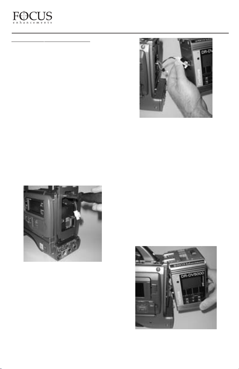
The FireStore DR-DV5000 is designed to
mount directly to full size JVC Professional DV
camcorders. When mounted to JVC GYDV5000/ 5000E/ 5001 camcorders, the DRDV5000 “hooks” to the rear of the camcorder
in the usual position of the battery. These
camcorders and DR-DV5000 also feature a 52pin connector that allows unique
communication between both devices. To
mount to a Professional DV series camcorder,
do the following:
FireStore DR-DV5000 User Guide
1) Remove and disconnect the attached battery
system from the camcorder(including battery
plate if applicable). Consult either your
camcorder’s documentation or documentation
from your battery system for more detailed
information on removing the battery system.
Leave the rubber gasket that was between the
camcorder and battery system in place.
ou are using a JVC GY-DV500, 550 or
2) If y
ou will first need to add the supplied
700, y
adapter plate to the rear of your camcorder (this
plate will allow the DR-DV5000 to “hook” to
the back of your camcorder.) Use the supplied
four screws to mount. GY-DV5000 series
camcorder owners can ignore this step.
3) DR-DV5000 features a two wire connector
with black and red cables that connects main
power between the DR-DV5000 and the
camcorder. Connect this to the equivalent
connector on the rear of your camcorder.
If you are using a digital battery system that
passes battery life status to the camcorder, and
are using a camcorder that is compatible with
these systems, connect the following cables
between DR-DV5000 and camcorder:
Anton/Bauer Digital Battery System
- Grey and Orange Cable
IDX Syncron Digital Battery System
- Blue and Red Cable
PAGE 9
Page 11
FireStore DR-DV5000 User Guide
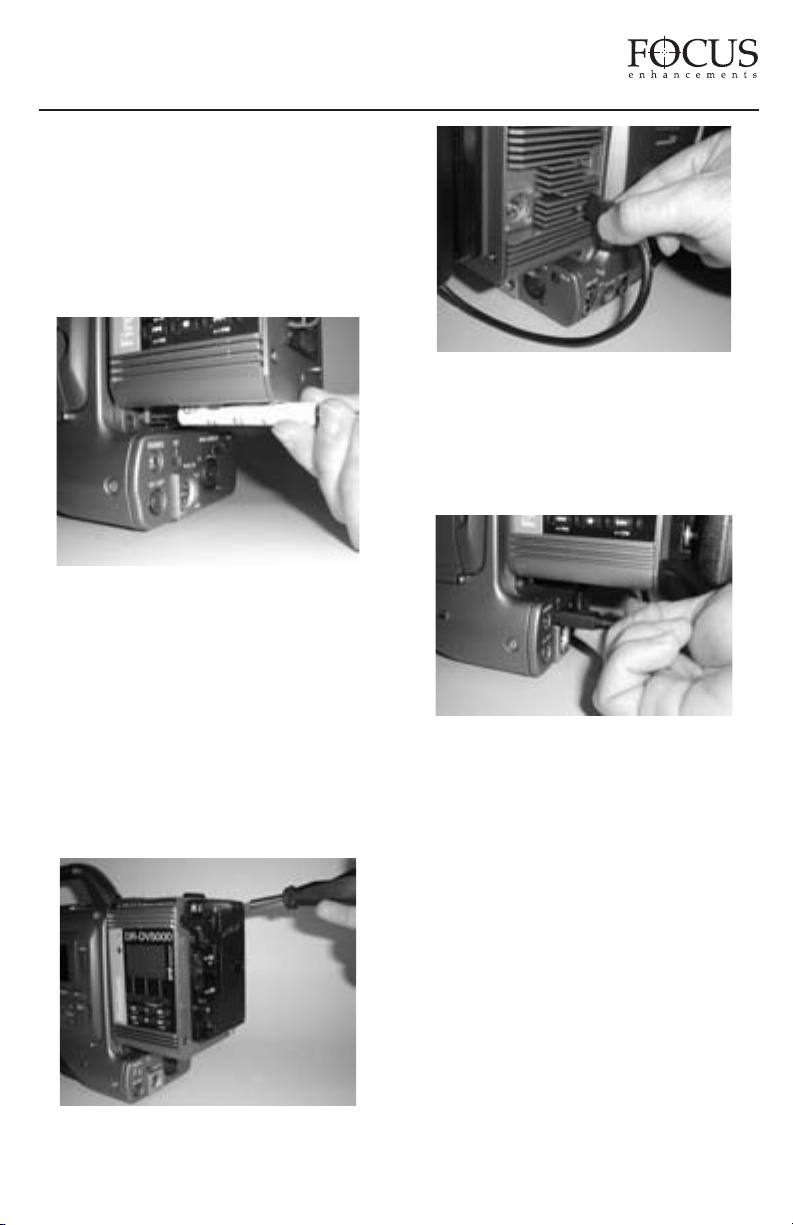
4) “Hook” the DR-DV5000 to the rear of the
the GY-DV5000 camcorder. If you are using
a JVC GY-DV5000 camcorder, use care to
ensure that the 52-pin connector on DRDV5000 mounts properly to the equivalent
connector on your camcorder. Harness any
loose cables into the “Hidey-Hole” on the DRDV5000.
5) Once mounted, secure the two captive screws
at the base of DR-DV5000 to the camcorder.
Ensure that no cables are “pinched” between
the DR-DV5000 and the camcorder.
7) Finally, connect a 6-pin to 4-pin FireWire
cable from the 6-pin FireWire port on DRDV5000 marked “DV I/O” to the 4-pin
FireWire port on the rear of the camcorder
marked “DV”.
6) Re-attach the battery system to the rear of
the DR-DV5000. Ensure to connect all power
cables and utilize the supplied gasket between
DR-DV5000 and the battery system. Harness
any loose cables in the “Hidey-Hole” on the
rear of DR-DV5000.
This final step is necessary on all JVC GYDV500, -550 and -700 series camcorders, but
may not be necessary on certain JVC GYDV5000 series camcorders. On certain models
(such as the GY-DV5000U(A) model), DV
input/output is done via the 52-pin connector
between camcorder and DR-DV5000. Check
with JVC for information on different models. A
flexible wire clamp located on the DR-DV5000
base provides strain relief for the cable.
PAGE 10
Page 12
INSERTING AND REMOVING
FIRESTORE FSHDD-1 FIREWIRE
DRIVES
The best way to get to know the FireStore
FSHDD-1 FireWire HDD is by studying the
supplied manual. The manual provides detailed
instructions and illustrations.
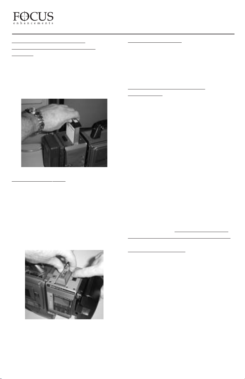
INSER
TING THE HDD: Insert the drive into
the slot on top of the DR-DV5000 unit. Ensure
that the power switch on the bottom side of the
drive is set to “On” before inserting. The drive
will only insert one way and features a “key”
on one side to prevent incorrect insertion.
Press down on the drive handle firmly until
the handle meets the top of DR-DV5000. If
power is on, you will observe the power LED
light up green.
FireStore DR-DV5000 User Guide
VING THE HDD: Slide the HDD
REMO
release latch on the DR-DV5000 top plate
toward the battery system. Once slid as far as
possible, hold the latch while at the same time
grasping the FSHDD-1 drive handle and pulling
the HDD out from DR-DV5000.
USING EXTERNAL FIREWIRE
DISK DRIVES
In addition to using FireStore FSHDD-1
ireWire HDDs in the internal slot on DR-
F
V5000, it is also possible to connect any
D
FireWire disk drive to the HDD I/O port on
DR-DV5000. Power a single FireWire disk
drive on DR-DV5000 at any given time (either
internal or external). If external drives are being
used as additional volumes to the inserted
FSHDD-1 FireWire HDD, it will be necessary
to provide external power to these drives. It may
also be necessary to partition and format drives
before use with DR-DV5000. See page 33 of
this user guide for instructions on preparing
drives before use.
NOTE: It is possible to “hot swap” both
internal and external FireWire HDDs on DRDV5000. Drives can be disconnected and
connected from the system without the need to
power cycle the unit. Ensure that DR-D
is in STOP mode before removing a disk drive.
V5000
PAGE 11
PHYSICAL FEATURES
Your FireStore DR-DV5000 features two main
surfaces, the front panel and the rear connector
panel.
FRONT PANEL
The front panel contains the backlit LCD
and nine buttons for controlling FireStore’s
functions. The top row of buttons act as Soft
Keys and provide the function displayed on the
bottom of the LCD.
Page 13
FireStore DR-DV5000 User Guide
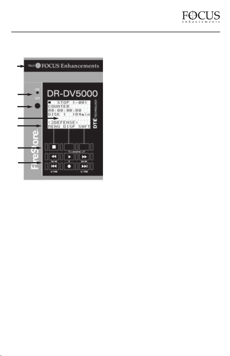
The front panel also features a tally light,
infrared remote sensor and power switch.
1
2
3
4
5
6
7
1. Tally Light
The DR-DV5000 red tally light is located at the
top of the DR-DV5000 front panel. In general,
this light will flash when DR-DV5000 is in
REC/PAUSE mode and be solid when in
RECORD mode. This light is also used to warn
the user when an error or warning message
appears on the DR-DV5000 LCD display. See the
“DR-DV5000 RECORD AND CONTROL LCD
AND CAMCORDER
MODES” section on page 42 of this User Guide
for more infor
2. Power Switch
FireStore DR-DV5000’s power switch is located on
the top left side of the front panel. This switch,
although mechanical, is controlled via software.
When the power switch is set to ON and then OFF,
in most cases the unit will take a moment to power
down. During this time, DR-DV5000 is ensuring
that any files that have not been closed properly in
VIEWFIDER DISPLAY
mation on tally light status.
a record session get closed. This prevents errors
occurring on particular files. When used with a
JVC GY-DV5000 series camcorder, DR-DV5000
communicates with the camcorder first before
power up or shutdown. In cases where the camera
power is switched to off when DR-DV5000 is
connected and ON, the camcorder will wait until
DR-DV5000 is powered down first before
powering both down. Again, this prevents errors
occurring on particular files.
3. Infrared Remote Sensor
The DR-DV5000 infrared remote sensor
is for use with the DR-DV5000 infrared remote
commander. For information on the DR-DV5000
infrared remote commander, see “DR-DV5000
REMOTE CONTROL COMMANDERS on page
40 of this User Guide. This port can be disabled in
infrared noisy environments if desired in the DRDV5000 settings menu.
4. LCD Display Screen
The DR-DV5000 LCD screen displays status,
setup and w
DR-D
default to ON, but this can be set to OFF or
AUTO-OFF mode if desired. See page 30 of
this User Guide for details.
5. Keypad Soft Key Function
The bottom line of the DR-DV5000 LCD screen
displays Soft Key functions for the top row of
buttons. Soft Keys allow the function of the top row
of buttons to change depending on particular modes.
K
6.
The top row of buttons on the DR-DV5000 front
panel are dedicated Soft Keys. Soft Key functions
change depending on what mode DR-DV5000 is
in. Current Soft Key function is displayed on the
bottom row of the LCD screen. The left key on the
top row of buttons acts as a Soft Key and as the
STOP key during record sessions. The right key
also acts as a SHIFT key which allows Standard
Keys to have a secondary function.
arning/error messages relating to
V5000. The LCD backlight is set as
eypad Soft Key
PAGE 12
Page 14
FireStore DR-DV5000 User Guide
7. Keypad Standard Keys
The bottom two rows of keys on the DRDV5000 keypad have dedicated functions such
as fast forward/back search, play, record, and
index forward back. Each key (except record)
also has a SHIFT mode which allows a
secondary function to be performed.
LCD DISPLAY
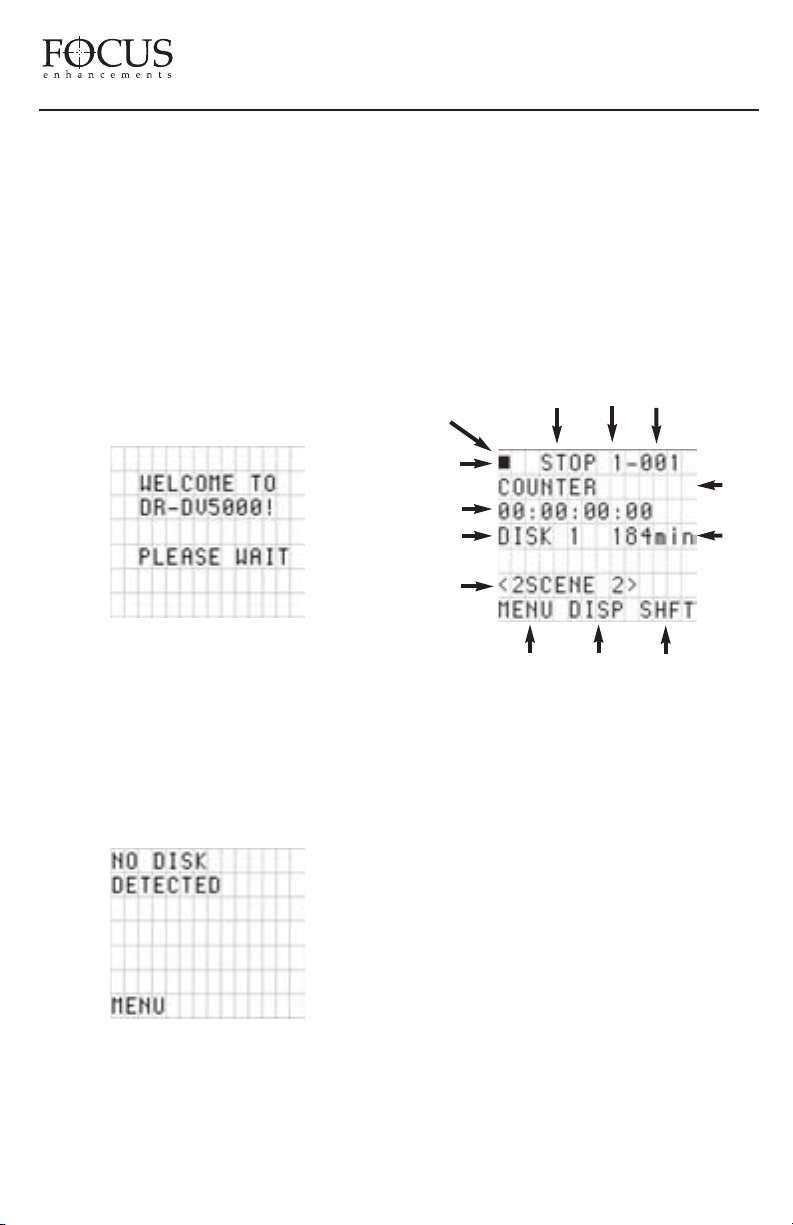
The DR-DV5000 LCD screen displays different
DR-DV5000 modes and states. On boot up,
DR-DV5000 will display the following screen:
Depending on the connected disk drive,
DR-DV5000 may or may not display “Please
Wait” during boot up.
Once booted up, if no disk drive is connected to
the DR-DV5000 (either through the internal slot
or externally via the HDD I/O port), the
following screen will appear:
the message “No Disk Detected” appears,
ensure you have a FSHDD-1 FireWire HDD
inserted properly. If the message “No Format
Detected” appears, you will first need to
partition and format the inserted drive. DRDV5000 will prompt you through the steps
required to perform a format.
Formatting will erase all data on disk!
Once ready for use, the DR-DV5000 default
Splash Screen will appear as follows:
3 4
WARNING:
5
2
1
6
7
8
9
13
10
1. Play/Record Status Symbol
This symbol displays a graphical representation
of the current DR-DV5000 playback, stop,
record or pause state.
11 12
Insert a FireStore FSHDD-1 FireWire HDD
to the internal drive slot or connect a FireWire
disk drive to the HDD I/O port. If a FSHDD-1
FireWire HDD comes from the factory, it
should be configured and ready to use. If
PAGE 13
2. Record/Play Status Indicator
In this space, DR-DV5000 will display a
character that notifies the user what record
or playback mode they are in. The characters
displayed and their respective modes are listed
on page 42 of this User Guide.
3. Current System Status
The current status of DR-DV5000 will be
displayed in this area. For instance, it will
display whether DR-DV5000 is in record, play,
stop, pause, fast search or slow motion modes.
Page 15

FireStore DR-DV5000 User Guide
4. Volume Number
The volume or disk number of the current clip
recording or playback session is displayed in this
area of the LCD. For example, a display value of
“2-014” identifies a track as being on volume 2.
5. Track or Clip Number
This area displays the current clip or track number
being recorded or played back. For example, a
display value of “2-014” identifies a track as
being clip 14 on volume 2. If a track number has
an "*" immediately following it, that particular
track has been marker as a "Keeper" track. See
page 15 of this User Guide for more information.
6. Timecode/User Bit Display Mode
This identifies the display mode for timecode
or user bit values. Selections are:
• COUNTER - counts frames during record
or playback of the current clip only.
• REMAINING - counts down the number of
frames available (time) on a particular disk during
a record session. In a playback session, this display
shows the remaining time on the current clip.
• SMPTE NTSC (or PAL) - Displays the external
timecode value being generated by a camcorder
or other device during a record session. Timecode
mode has to be set to EXT TC for this function to
operate (see page 28 of this User Guide). In
playback mode, this displays the embedded
SMPTE timecode value in a particular track.
• UB NTSC (or PAL) - Displays the set user
bit value in a particular clip. A user bit value
must be added for this to display (see page 29
of this User Guide).
7. Timecode or User Bit Value
Displays the timecode or user bit value of
display mode selected.
8. Current Disk Volume
Displays the current disk volume in relation to
available space.
Available Space on Volume
9.
Displays the space in time available on the
current volume.
10. Soft Key One Function Display
Displays the current function related to Soft
Key one (left key on the top row of buttons).
This is typically the main soft key for opening
the DR-DV5000 MENU and is also used as a
STOP key during record and playback sessions.
11. Soft Key Two Function Display
Displays current function of Soft Key two
(middle key on the top row of buttons).
12. Soft Key Three Function Display
Displays current function of Soft Key three
(right key on the top row of buttons).
13. Folder Display
Displays folder that current clip is in. If blank,
clip is not in a folder. If folder appears in
brackets (e.g. <2SCENE 2> ), the DR-DV5000
PLAY FROM menu is set to FOLDER LIST.
See page 22 of this User's Guide for more details.
• ABSOLUTE - Displays an absolute timecode
value for the particular session (sum of all
COUNTER timecode on connected v
olumes).
This is mainly used when DR-DV5000 is set to
AV/C mode and is being controlled by an external
FireWire device such as a computer.
FRONT PANEL BUTTONS
The DR-DV5000 front panel features nine buttons.
The three buttons on the top row are “Soft Keys”
w
hich allow different functions to be controlled
depending on the mode DR-D
V5000 is in. Use the
PAGE 14
Page 16
FireStore DR-DV5000 User Guide
bottom line of the LCD display to identify the
current soft key function. The remaining six
buttons have a fixed function. Several of them
also feature a secondary function that can be
accessed by pressing the SHIFT key (usually
the right Soft Key).
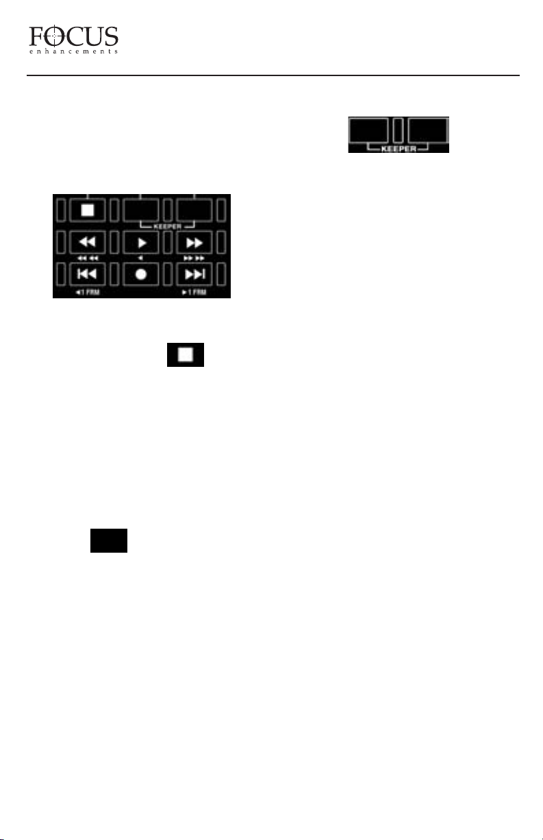
DR-DV5000 buttons have the following functions:
Soft Key 1 and STOP Key
Stops whatever is the selected mode and returns
DR-DV5000 into Pause. A second press puts
DR-DV5000 into STOP (standby with splash
screen). Splash screen is either a gray screen
or first frame of the selected clip depending on
the PREVIEW mode (see page 30 for more
info.) Key also acts as a dedicated soft key
for triggering mode/function that appears
immediately above key in the DR-DV5000 LCD
y except during record and playback.
displa
Soft Key 2
Dedicated soft key for triggering mode/function
that appears immediately above key in the DRDV5000 LCD display.
Soft Key 3 and SHIFT Key
Dedicated soft key for triggering mode/function
that appears immediately above key in the DRDV5000 LCD display. This key is also commonly
used to enter the SHIFT mode. To execute a shift
function, press SHIFT and another key at the
same time.
Keeper Clip and Scene Marking Keys
FireStore DR-DV5000 features the ability to
quickly mark clips during record and playback
to a single “Keeper” folder or multiple,
prenamed “Scene Marking” folders. It is
possible to use the front keypad for Scene
Marking or Keeper Marking but it is necessary
to first select either Keeper or Scene Marking
under FOLDER PREFENCES in the SETUP
menu as it is not possible to use both at once.
See page 31 of this User Guide for more
information.
If you have selected the KEEP preference, it is
possible to mark the current clip by pressing
and holding Soft Key (3) followed by Soft Key
(2). KEEPER can be marked on the current clip
during recording, playback or in stop mode.
The KEEPER label and a relational line
between the two keys is silk-screened on the
DR-DV5000 front panel. It is also possible to
mark a clip as a KEEPER using the KEEPER
button on one of the optional remote control
units. Once a clip has been marked as a
KEEPER, an asterix (*) will appear next to
the track number ("X-XXX*) on the LCD. To
add all clips marked as a KEEPER to the
Keeper Folder on the disk drive, select
UTILITIES -> ORGANIZE FOLD from
the DR-DV5000 menu.
If you have selected the SCENE MARK
preference, pressing and holding Soft Key (3)
followed by Soft Key (2) allows you to mark
each clip into particular pre-named folders on
disk (up to 10 folders can be prenamed. Default
names for the folders are 0 through 9. See page
35 of this User Guide to setup folders). By
holding Soft Key (3) down and repeatedly
pressing Soft Key (2), it is possible to scroll
though the available folders. It is also possible
to SCENE MARK clips to folders using the
numeric keypad on the supplied remote control
PAGE 15
Page 17
FireStore DR-DV5000 User Guide
units. SCENE MARK can be marked on the
current clip during recording, playback or in
stop mode and once selected, the clip will be
marked for placement into that particular folder.
To add all SCENE MARKED clips to their
respective folders on the disk drive, select
UTILITIES -> ORGANIZE FOLD from the
DR-DV5000 menu.
For more on KEEPER and SCENE
MARKING, see page 35 of this manual.
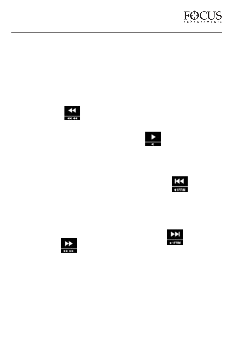
Backward Search Key
Pressing the backward search button multiple
times will result in increases in the search speed
during playback. This mode is bidirex in
forward X times normal search speed, a press
of the Back Search button will result in FF
speed being slowed down by one step. For
instance, if user is in 10X FF speed and presses
the Back Search button once, they will now be
in 2X FF mode. This applies vice versa for
backward search speeds. Speed resolution is as
follows: (NTSC, PAL will have slightly
different multiples for < 1X):
REVERSE : -30X, -10X, -2X, -1X (reverse
play), -1/2X(-15fps), Still.
FORWARD: Still, +1/2X (+15fps), +1X (play),
+2X, +10X, +30X
Forward Search Key
Pressing the forward search key multiple times
will result in increases in the search speed
during playback. This key has the same
characteristics and bidirex function as the
backward search key listed above.
Standard forward search and reverse search also
have a “higher resolution” mode where more
speeds are available. By pressing and holding the
SHIFT key plus the forward or backward search
key, the user has access to a larger number of
playback speed choices. This mode is the same as
Standard Forward Search in that it is also bidirex.
REVERSE: -30X, -25X, -18X, -15X, -12X, 10X, -8X, -5X, -4X, -3X, -2X, -1X, -15fps, 10fps, -6fps, -5fps, -3fps, -2fps, -1fps, Still
FORWARD: Still, +1fps, +2fps, +3fps, +5fps,
+6fps, +10fps, +15fps, +1X, +2X, +3X, +4X,
+5X, +8X, +10X, +12X, +15X, +18X, +25X,
+30X.
NOTE: When using the DR-DV5000 remote
control units, holding down the particular button
will not repeat the function as it does on the DRDV5000 control panel. For repeat sequences, the
button must be pressed multiple times.
Play Key
Starts playback of the selected clip. By pressing
and holding the SHIFT key plus the play
button, DR-DV5000 will immediately go into
reverse play mode.
Backward Index Key
Returns to the beginning of the current clip if in
playback mode. Two presses in sequence will
return to the previous clip during playback. In
Stop mode a press will return to the beginning
of the pre
F
vious clip.
ard Index Key
orw
Skips forward to the next sequential clip for
playback.
The forward index and backward index buttons
also have a SHIFT mode where users can move
one frame forward or one frame backward.
When DR-DV5000 is in PLAY or PAUSE mode
and the user presses and holds the SHIFT key
plus the forw
ard or backward index keys, it is
possible to forward one frame or backward one
frame with each press. If in PLAY mode, DRDV5000 will immediately go into PAUSE mode
on the particular frame.
PAGE 16
Page 18
FireStore DR-DV5000 User Guide
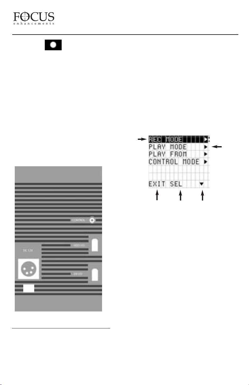
Record Key
Pressing this button once puts DR-DV5000 into
REC-PAUSE mode. A second press starts a
recording session. If this button is pressed
while a recording is in progress, DR-DV5000
will create a new clip on disk without dropping
any frames.
REAR CONNECTOR PANEL
The rear connector panel features a 6-pin
FireWire port for DV video I/O (A), a 6-pin
FireWire port for connection of external
FireWire drives or a computer (B), a 4-pin XLR
DC power input (C) and a 3.5mm control cable
input for RS232C or GPI (D).
(D)
MAIN MENU, press SOFT KEY (1) while in STOP
mode. Available items in the MAIN Menu are:
REC MODE
PLAY MODE
PLAY FROM
CONTROL MODE
HDD BYPASS
REC FORMAT
SETUP
UTILITIES
The following MENU SCREEN will appear:
1
2
3 4 5
1. Current Menu Item
Indicates the currently highlighted menu item.
(B)
(A)
(C)
DR-DV5000 MENUS AND FUNCTIONS
FireStore DR-DV5000 features a comprehensive
menu system which allows a number of features to
be initiated and setup. To enter the DR-DV5000
PAGE 17
2. Sub-Menu Available
Indicates a menu item that has a sub-menu
available. By pressing the SEL Soft Key, it is
possible to enter the sub-menu.
Exit
3.
Pressing EXIT will exit the DR-DV5000 MAIN
MENU screen.
4. Select
Pressing SEL will select the current menu item.
If a sub-menu is available, that will open. If a
sub-menu is not available, this command simply
enables or selects the menu item.
Scroll Arrow
5.
This command allows for scrolling through
menu items.
Page 19
FireStore DR-DV5000 User Guide
RECORD MODE MENU
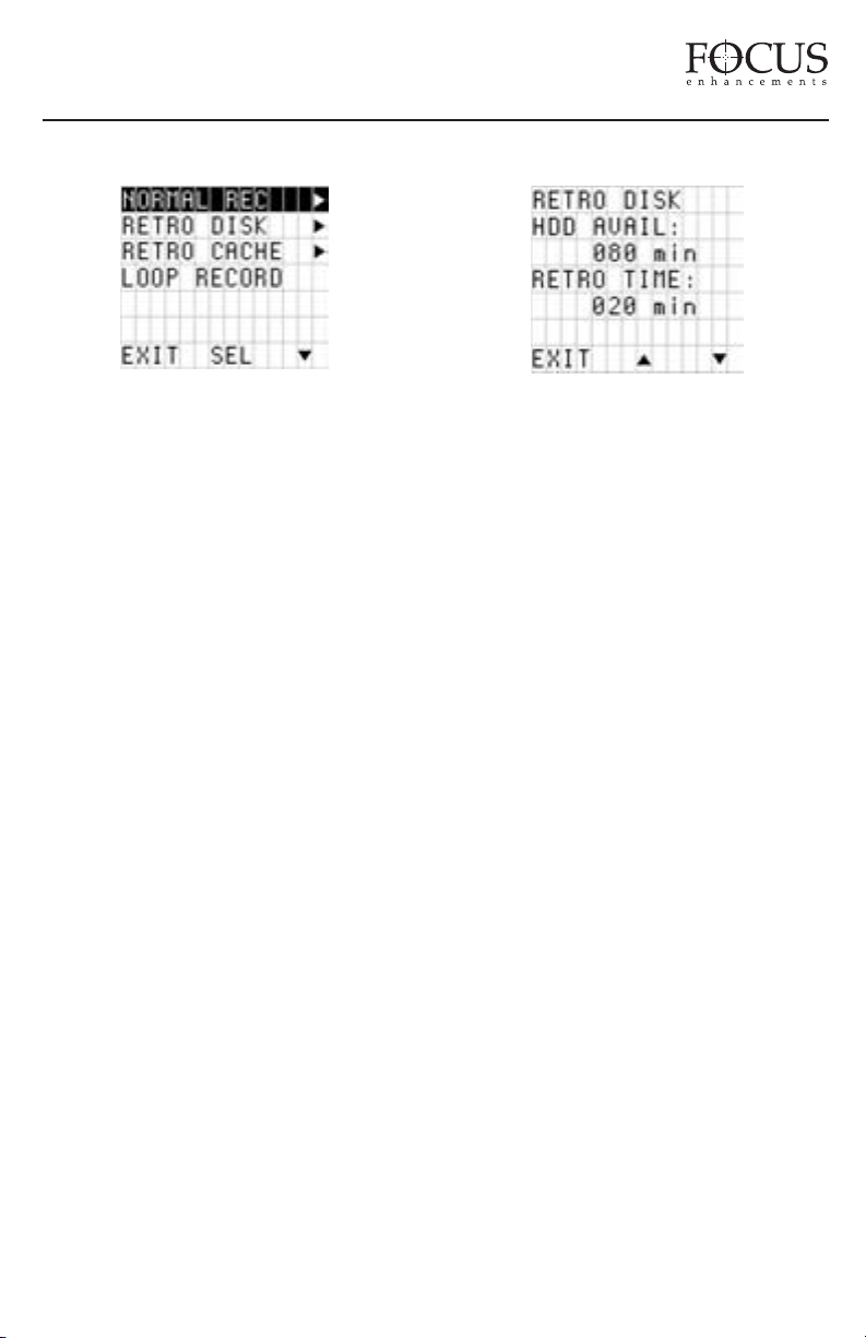
The DR-DV5000 RECORD MODE MENU allows
different record functions to be enabled. User
simply selects the mode. Pressing SEL will open
the sub menu. Pressing EXIT will exit back to the
menu screen. Once a particular mode is selected in
the Record Mode menu, the unit will remain in
that mode until a different mode is selected.
Available items in the RECORD MENU are:
NORMAL REC
RETRO DISK
RETRO CACHE
LOOP RECORD
SNAP
TIME LAPSE
DUMP TO DISK
DUMP TO TAPE
NOTE: When an inserted or attached HDD is
nearly full, in some record sessions, the HDD time
remaining may display “001min” remaining. If
RECORD is triggered, DR-DV5000 will sometimes
display NO SPACE LEFT. It is advised that when
a disk drive is close to being full, other disk drives
are readily available in order to avoid lost footage.
Normal Record
Standard and default record mode. When REC
is triggered, DR-DV5000 begins standard
recording. A single press of a STOP trigger will
put DR-DV5000 into REC PAUSE mode. A
second press puts DR-D
V5000 into STOP mode.
Retro Disk Record Mode
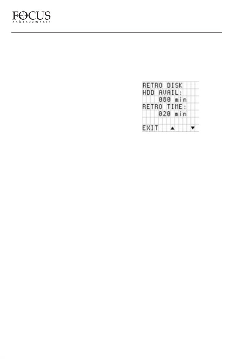
RETRO DISK Record Constantly buffers video in
a loop to a determined amount of space on the
HDD so that when record is triggered, a retro time
period can be added to the beginning of any clip.
RETRO DISK has the following characteristic.
Pressing a REC TRIGGER when in RETRO
DISK mode puts DR-DV5000 into a RETRO
DISK state (DR-DV5000’s tally light will flash as
if in PAUSE state). DR-DV5000 is actually
recording in this state, but until the RECORD
TRIGGER is pressed a second time, the video
recorded will record over itself in a continuous
loop. RETRO DISK always keeps at least the
amount of time that is selected by the end user in a
series of one minute clips. For instance, if the user
sets the RETRO DISK value to 3 minutes, they
will always have 3 minutes (made up of three, one
(1) minute clips) of video saved to disk. As the
recording goes past the 3 minute point, a fourth
clip is created. Once that clip reaches one minute,
the oldest of the previous 3 clips is deleted.
Another fourth clip is then created.
If a user selects a RETRO session that is 60
minutes or greater, instead of one minute clips,
DR-DV5000 creates 9 minute, 13 second clips
(2GB clips on disk). The characteristics of RETRO
DISK remains the same. The larger file size
prevents DR-DV5000 reaching its 999 track
limitation for very long RETRO records. Due to
the larger files sizes, the maximum amount of
drive space available is decreased in order to
accommodate the last recording in a session. For
instance, if a user has 90 minutes of disk space
PAGE 18
Page 20
FireStore DR-DV5000 User Guide
remaining, after the user sets RETRO record to
greater than 60 minutes, the available space
changes to 88 minutes of available disk space. If
the user sets RETRO time to 88 minutes, the
recording will be made up of about nine and a half
9 minute, 13 second clips. There must be space
available in this situation in order to record the final
clip which eventually will right over clip 1. This
ensures that at any given time, at least 88 minutes
of video exists after a compete RETRO DISK
record loop.
TE: DR-DV5000 must always have at least one
NO
minute of disk space (under 60 minutes) or 9
minutes, 13 seconds of disk space (when RETRO
DISK value is set to greater than 60 minutes)
remaining in addition to the RETRO DISK value
that has been set, in order to function correctly. For
instance, it is not possible to set a RETRO DISK
value of one minute if only one minute of disk
space remains.
Once RETRO DISK time is set, the user can exit
the Menus and return to the Main Screen. An “L”
will now appear next to the record symbol on DRDV5000’s display. Pressing the REC trigger once
will put DR-DV5000 immediately into RETRO
DISK RECORD. Clips are being recorded to disk
for X number of minutes in one minute increments
(each as a separate track). The tally light will flash
(as if the unit is in pause). When the REC trigger is
pressed, DR-DV5000 will kick out of RETRO
DISK mode and go into standard record. All one
minute tracks in the set loop sequence will appear
and be saved as their own tracks on disk (e.g. 1001, 1-002, 1-003 etc.) except for the recording that
was in progress, which takes on the characteristics
of a standard track. At this stage, DR-DV5000 is
essentially in standard record mode (the “L” on the
display will disappear). No frames will be lost
across tracks during the record session. Once
paused, the unit will return to RETRO DISK record
mode again (the “L” will reappear in the LCD and
viewfinder) for further RETRO recordings or until
it is disabled n the RETRO DISK Menu.
RETRO DISK can be used in LOCAL,
SYNCRO SLAVE RECORD and SPLIT
SLAVE RECORD control modes.
WARNING: Make sure DR-DV5000 is in STOP
mode before removing the disk drive from the
system. Do not attempt to remove when DRDV5000 is in REC or REC-PAUSE mode.
Retro Cache Record Mode
RETRO CACHE RECORD constantly buffers
video in a loop to a 10 second data buffer to cache
video so that when record is triggered, a retro time
period can be added to the beginning of any clip.
NOTE: Retro cache mode utilizes the same
memory data buffer as used for shock
protection on DR-DV5000. If Retro Cache
mode is not being used, all the DR-DV5000
cache is available for shock protection. If Retro
cache is ON, the shock buffer time will be
reduced by the amount of cache time that is
selected and therefore performance may vary.
RETRO CACHE has the following
characteristic. Pressing a REC TRIGGER when
in RETRO CACHE mode puts DR-DV5000 into
O CACHE state (the TALLY light on
a RETR
V5000 will flash as if in PAUSE state).
DR-D
V5000 is actually recording in this state,
DR-D
but until the RECORD TRIGGER is pressed a
second time, the video recorded will record over
itself in a continuous loop. It is much the same
as RETRO DISK recording in theory except that
it utilizes a data buffer that is separate to the
disk drive to cache video. RETRO CACHE is
also accurate down to the frame instead of the 1
minute clips used in RETRO DISK. Once a
RETRO CACHE value is set, pressing the REC
trigger once will put DR-DV5000 immediately
into RETRO CACHE Record. A “C” will now
PAGE 19
Page 21
FireStore DR-DV5000 User Guide
appear next to the record symbol on DRDV5000’s display and also in the camcorder’s
viewfinder. Video is being recorded to the DRDV5000 cache. The tally light will flash (as if
the unit is in pause). When the REC trigger is
pressed, DR-DV5000 will kick out of RETRO
CACHE record mode and go into standard
record (the “C” on the display will disappear).
Any clip that is recorded in this mode will have
the contents of the cache added to the beginning
of the clip. Once paused, the unit will return to
RETRO CACHE record mode again (the “C”
will reappear in the LCD and viewfinder) for
further RETRO CACHE recordings or until it is
disabled in the RETRO CACHE REC Menu.
RETRO CACHE RECORD can be used in
LOCAL, SYNCRO SLAVE RECORD and
SPLIT SLAVE RECORD control modes.
WARNING: Make sure DR-DV5000 is in STOP
mode before removing the disk drive from the
system. Do not attempt to remove when DRDV5000 is in REC or REC-PAUSE mode.
Loop Record
The LOOP RECORD feature allows video to
be recorded to available disk space on the
connected disk drive(s) in an endless loop. To
use LOOP RECORD, simply select in the DRDV5000 RECORD MENU. Once highlighted,
an “O” will appear on the top line of the DR-
V5000 LCD next to the PLAY/RECORD
D
STATUS SYMBOL. When record is triggered,
DR-DV5000 will begin recording on available
disk drive space. Like the RETRO DISK
feature, when DR-DV5000 is in LOOP
RECORD mode, it records sequential one
minute clips to the disk drive. When only one
minute remains on the disk drive, DR-DV5000
loops back to record over the oldest one minute
clip and so on. It is possible to PAUSE DRDV5000 in this mode and then continue a
LOOP RECORD by starting record once again.
DR-DV5000 will remain in LOOP RECORD
mode until a recording is stopped. Once
stopped, the files on disk will not be erased if a
new LOOP RECORD session is begun.
If the available time on disk is 60 minutes or
greater, DR-DV5000 will record sequential 9
minute, 13 second long clips instead of one
minute clips. The larger file size prevents DRDV5000 from reaching its 999 track limitation
for very long LOOP RECORDS.
Snap
When SNAP is selected and REC is triggered, a
single frame is grabbed. SNAP can be used
with LOCAL, and SPLIT SLAVE RECORD
control modes.
If SNAP is the RECORD MODE when power
is cut to the unit or it is turned off, on re-boot,
DR-DV5000 will be in NORMAL REC mode.
Time Lapse
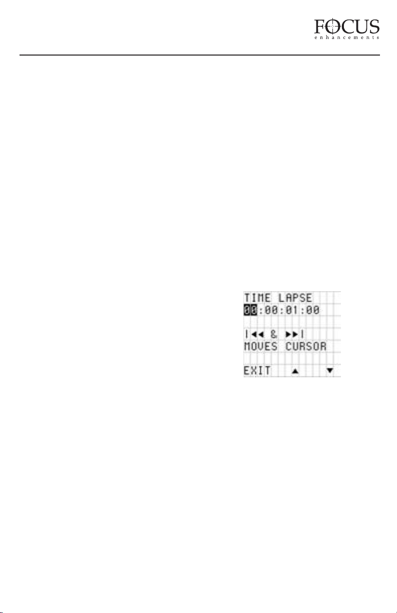
It is possible to select a time lapse interval of up
to twenty-four hours. Interval is the period of
time between DR-DV5000’s capture of a single
frame of video (a value of 00:00:01:00 means
one frame will be recorded every second). REC
INTERVAL is set by the user pressing the up
and down buttons. Time is selectable in seconds
(up to 59), then minutes up to 59. Buttons can
be released at any time to slow advance. EXIT
will exit back to the menu screen.
Dump To Tape
NOTE: This feature is for use with JVC GY-
DV5000 series camcorders only. Do not press
DR-DV5000’s REC button during a DUMP TO
TAPE session.
PAGE 20
Page 22
FireStore DR-DV5000 User Guide
In order to use this mode, the GY-DV5000
camcorder must be in VTR Mode and a record
inhibit tape must be in the camcorder. DUMP
TO TAPE does not function when camcorder
is in CAM mode. To initiate, user simply
inserts tape to the DR-DV5000 transport and
ensures a disk is inserted with footage. If DRDV5000 is unable to perform DUMP TO
TAPE, the DR-DV5000 LCD will display
“DUMP INHIBIT”. It is not possible to use
SPLIT SLAVE mode with DUMP TO TAPE.
The DUMP INHIBIT warning message will
appear on the DR-DV5000 LCD display if no
tape is present, the record inhibit tab on the
tape is set to SAVE, the camera is not in VTR
mode or the HDD is empty.
A grey picture with no audio will be recorded
for approximately 10 seconds at the beginning
of a DUMP TO TAPE session. During this 10
seconds, timecode is static.
Dump To Disk
NOTE:
This feature is for use with JVC GYDV5000 series camcorders only. Do not press
DR-DV5000’s REC button during a DUMP
TO DISK session.
PLAY MODE MENU
The DR-DV5000 PLAY MODE MENU allows
different playback functions to be enabled. User
simply selects the mode. Pressing EXIT will
exit back to the menu screen. Once a particular
mode is selected in the Play Mode menu, the
unit will remain in that mode until a different
mode is selected.
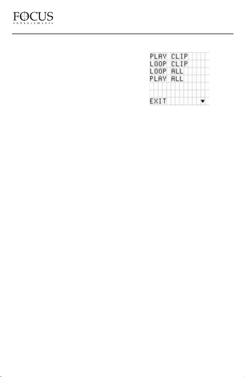
Available items in the PLAY MODE MENU are:
PLAY CLIP
LOOP CLIP
LOOP ALL
PLAY ALL
Play Clip
In order to use this mode, the GY-DV5000
camcorder must be in VTR Mode and there
must be available disk space on the DRDV5000 disk drive. DUMP TO DISK does not
function when camcorder is in CAM mode. To
initiate, user simply inserts tape. Tape will be
rewound if required before the Dump to Disk
process begins. If DR-DV5000 is unable to
perform DUMP TO DISK, the DR-DV5000
LCD will display “DUMP INHIBIT”. Before
using DUMP TO DISK mode, ensure that
DR-DV5000 record mode is NOT set to TIME
LAPSE. It is not possible to use SPLIT
SLAVE mode with DUMP TO DISK. The
DUMP INHIBIT warning message will
appear on the DR-DV5000 LCD display if no
tape is present, the camera is not in VTR
mode or the HDD is full.
PAGE 21
In this mode, DR-DV5000 will play the
selected clip from start to finish when the
PLAY button is pressed. At the end of the
particular clip, DR-DV5000 will pause.
Loop Clip
In this mode, DR-DV5000 will play the
selected clip from start to finish. Immediately
after completing the clip, DR-D
gin playing the clip again without a pause. It
be
y in this state until stopped.
will sta
V5000 will
Loop All
In this mode, DR-DV5000 will play the entire
contents of the disk (all clips from the selected
clips) in order from start to finish. At the end of
the last clip, DR-DV5000 will begin to play from
Page 23
FireStore DR-DV5000 User Guide
the beginning of the first clip again without a
pause. It will stay in this state until stopped.
Play All
In this mode, DR-DV5000 will play the entire
contents of the disk (all clips) in order from start
to finish. At the end of the last clip, DR-DV5000
will pause.
NOTE: Play Mode operation varies depending
on whether Track List or Folder List is selected
in the PLAY FROM menu. When Track List is
selected, clips are played back based on the
entire disk drive. When Folder List is selected,
clips are only played from the selected folder.
PLAY FROM MENU
The DR-DV5000 PLAY FROM MENU allows
the user to select where clips will be played
back from. There are two options available:
Track List
Select a particular folder to play clips from.
Highlighted folder is the selected folder after
exit. Once set and when PLAY is pressed, only
clips within that particular folder will playback.
If Folder List is selected, all PLAY MODES
relate to clips in the selected folder only.
If the DR-DV5000 PLAY MENU is set to
"TRACKLIST" the name of the SCENE
MARKED folder will appear without brackets on
the LCD display (e.g. 2 DEFENSE). If the PLAY
OM menu is set to "FOLDERS", the name of
FR
the SCENE MARKED folder will appear in
brackets on the LCD display (e.g. 2 <DEFENSE>.
CONTROL MODE MENU
The DR-DV5000 CONTROL MODE MENU
allows different control options to be enabled.
User simply selects the mode. Pressing EXIT
will exit back to the menu screen. Once a
particular mode is selected in the Control Mode
menu, the unit will remain in that mode until a
ferent mode is selected.
dif
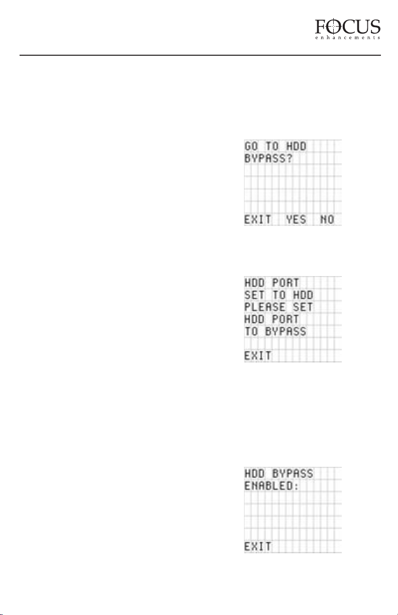
When this setting is selected, all clips on attached
disk drives will be played back sequentially based
on the order of their base file name regardless of
whether they have been marked in the KEEPER
or SCENE MARKING folders. If Track List is
selected, all PLAY MODES relate to all clips on
the connected disk drives.
Folder List
When this setting is selected, it is possible to
play back clips only from a selected folder.
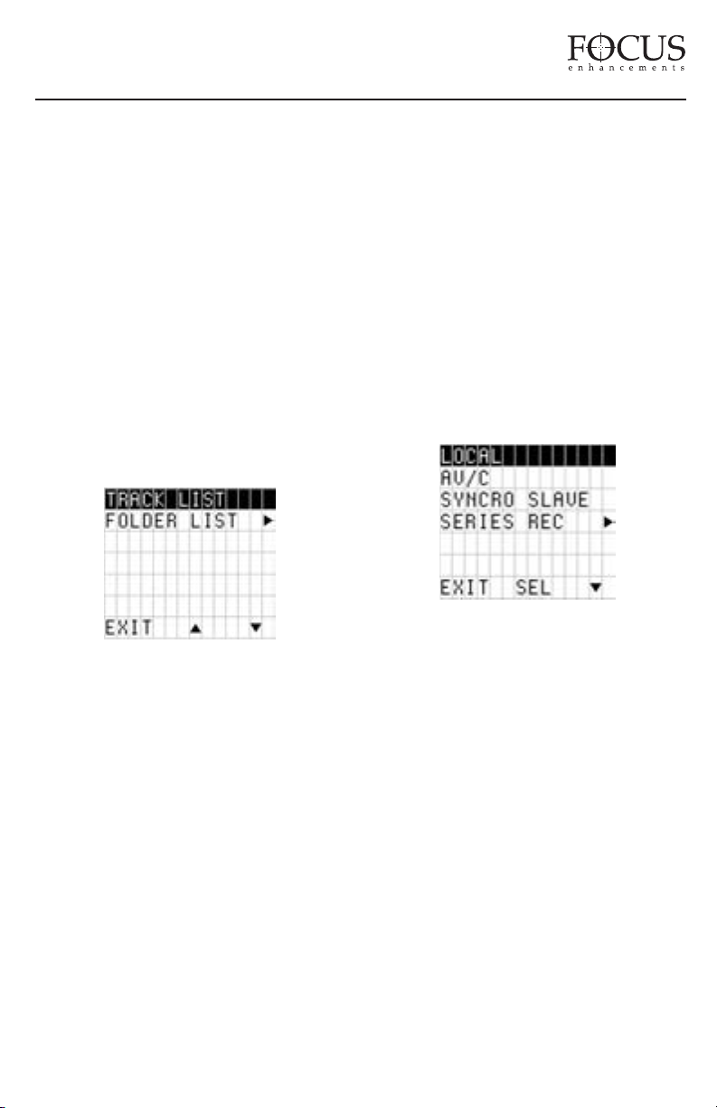
vailable items in the CONTROL MODE
A
MENU are:
LOCAL
AV/C
SYNCRO SLAVE
SERIES REC
SPLIT SLAVE
Local
In this mode, DR-D
uttons only. The camcorder tape transport
panel b
V5000 is controlled via the front
and DR-DV5000 have independent control.
PAGE 22
Page 24
FireStore DR-DV5000 User Guide
AV/C
AV/C is utilized in PLAYBACK and RECORD
situations where DR-DV5000 is controlled by
an external FireWire device (such as a DV NLE
system), connected to the "DV I/O port" on
DR-DV5000. For example, you may like to
record the ouput of your NLE's timeline to DRDV5000.
NOTE: AV/C is NOT for use in DR-DV5000
RECORD MODES.
Syncro Slaved
In SYNCRO SLAVED mode, the camcorder and
DR-DV5000 share the same REC trigger and DRDV5000 is slaved to the camcorder. Once set and
the user exits the CONTROL MENU, they will
return to the default splash screen. DR-DV5000
also immediately enters REC PAUSE mode and a
“Y” appears next to the record symbol on the
camcorder viewfinder and LCD (GY-DV5000
series only) as well as the DR-DV5000 LCD. All
triggers of REC and REC PAUSE are controlled
by the camcorder exclusively. Every time the
camcorder REC button is pressed, DR-DV5000
goes into the particular RECORD MODE that is
selected. When pressed a second time, DRDV5000 goes into REC PAUSE. Another press of
the REC button on the camcorder again starts the
particular RECORD MODE that is selected. At
this point, a new track is created on disk. Timecode
generated by the camcorder is recorded to the file
when DR-DV5000 is set to EXT TC mode.
When used with RETRO DISK or RETRO
CACHE modes, as soon as SYNCRO SLAVE is
set, the camcorder begins recording to disk. A
press of the REC trigger on the camcorder kicks
SHFT) are locked out when in this mode, as is
wired or infrared remote control units. If in VTR
mode on the camcorder, all keys work. The user is
only able to exit SYNCRO SLAVE by entering the
CONTROL MENU which they can do directly by
pressing the MENU button when on the DRDV5000 default splash screen. If the camcorder is
set to VTR mode, DR-DV5000’s control panel
becomes active in order to allow playback.
If a tape ends while using SYNCRO SLAVE
mode, DR-D
OP a recording, eject the tape in the transport
ST
V5000 will continue to record. To
and then it is possible to continue REC and
REC/PAUSE functions on DR-DV5000 with the
camcorder’s VTR button and the camcorder is set
to REGEN or PRST/REC.
NOTE: If DR-DV5000 is set to EXT TC when in
SYNCRO SLAVE mode, EXT TC will stop once
the tape in GY-DV5000 ends. Use a different TC
mode when using SYNCRO SLAVE.
Series Record Mode
SERIES
automaticall
RECORD will start recording to disk
y when a tape is close to the end of
a record session. Once recording to disk has
started, REC will continue until stop is pressed
on DR-DV5000.
DR-DV5000 out of RETRO DISK or RETRO
CACHE and goes into standard REC. When the
camcorder is triggered back into REC PAUSE
mode, DR-DV5000 once again goes into RETRO
DISK or RECORD CACHE mode again. The DRDV5000 buttons (other than MENU, DISP and
PAGE 23
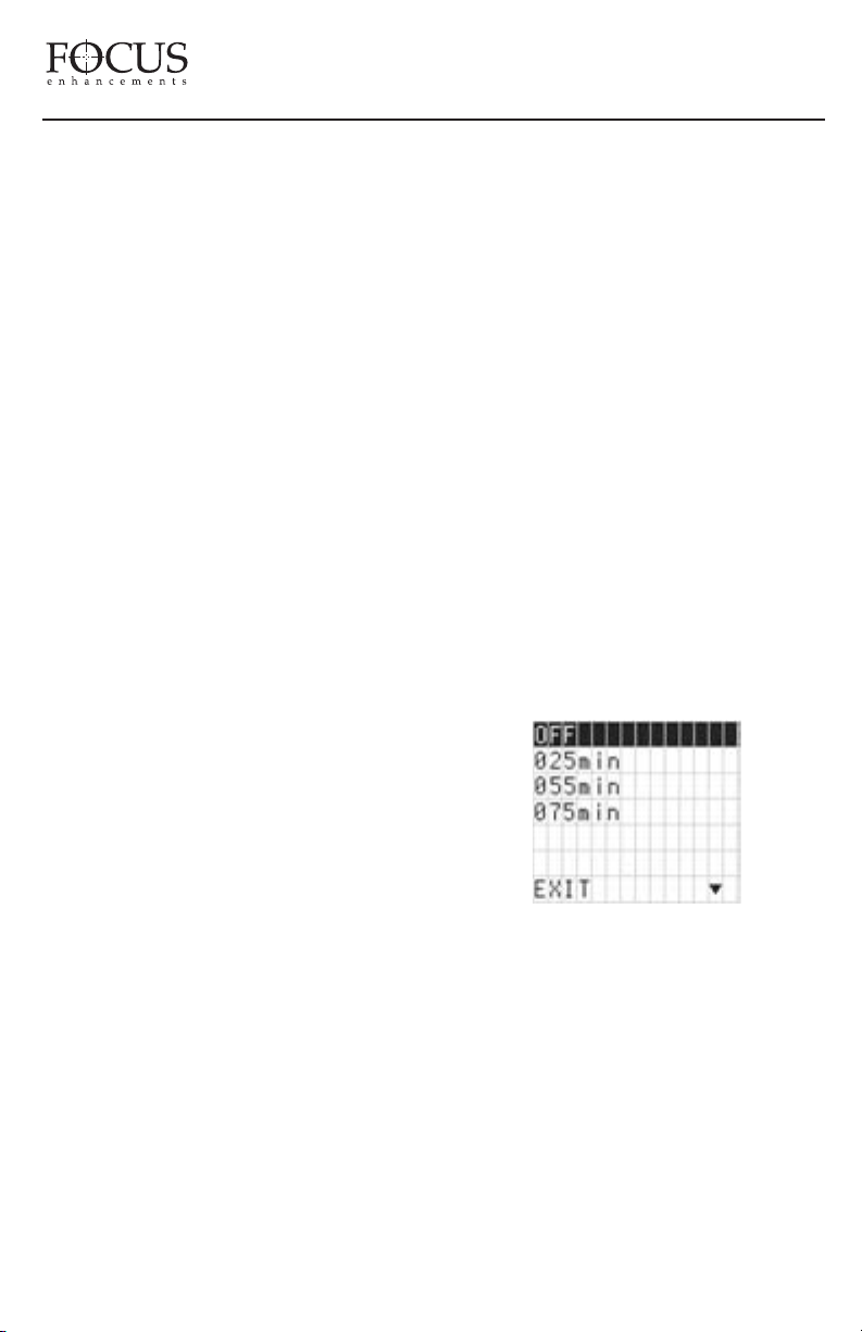
In SERIES RECORD mode, user simply selects
the particular length tape they are using in the
camcorder by pressing the down button. OFF
disables the feature. EXIT will exit back to the
default splash screen if SERIES RECORD is
enabled. An “F” will appear in the camcorder’s
Page 25
FireStore DR-DV5000 User Guide
viewfinder (GY-DV5000 series only) as well as
the DR-DV5000 front panel LCD. RETRO
DISK RECORD and RETRO CACHE
RECORD are not possible with SERIES
RECORD.
When in SERIES RECORD and on the default
splash screen, pressing MENU will go directly
to the SERIES RECORD menu. It is then
possible to EXIT SERIES RECORD mode.
Split Slave
In this mode, DR-DV5000 is controlled
by the camcorder, but separately from the
camcorder’s tape transport. DR-DV5000 is
slaved to the GY-DV5000 camcorder’s VTR
button on the side of GY-DV5000. Every time
this button is pressed, DR-DV5000 directly
begins recording (not REC-PAUSE) in the
particular RECORD MODE that is selected.
When pressed a second time, DR-DV5000 goes
into STOP mode (except in RETRO RECORD
modes). Another press of the VTR button on
the camcorder again starts RECORD again. At
this point, a new track is created on disk.
When used with RETRO DISK or RETRO
CACHE modes, as soon as SPLIT SLAVE is
set, the DR-DV5000 begins recording to disk. A
press of the VTR REC trigger button on the
side of the GY-DV5000 camcorder kicks DR-
V5000 out of Retro Disk or Retro Cache and
D
goes into standard REC.
When the VTR trigger
button on the side of the GY-DV5000
camcorder is triggered back into REC PAUSE
mode, DR-DV5000 once again goes into
RETRO DISK or RETRO CACHE mode.It is
possible to play a tape back on GY-DV5000 and
record to DR-DV5000 in SPLIT SLAVE mode.
WARNING: Do not connect DR-DV5000 to a
computer until the HDD port in the set up
menu has been set to Bypass.
When HDD Bypass is selected, the following
will display on the DR-DV5000 LCD:
If this screen does not appear, the DR-DV5000
HDD I/O port is set for use with external drives.
To set the HDD Port, go to the Main Menu and
select SETUP -> HDD PORT to set. User is
prompted as in screen above: Once set, it will be
le to set DR-DV5000 to HDD Bypass mode.
possib
Once in HDD Bypass mode, the following LCD
display will appear:
HDD BYPASS
HDD Bypass mode allows the connected
FireWire HDD to be mounted/dismounted to a
computer without removing. In this mode, the
computer connects to the HDD I/O port on the
DR-DV5000 Rear Connector Panel.
o Exit this mode, simply press the EXIT key.
T
PAGE 24
Page 26
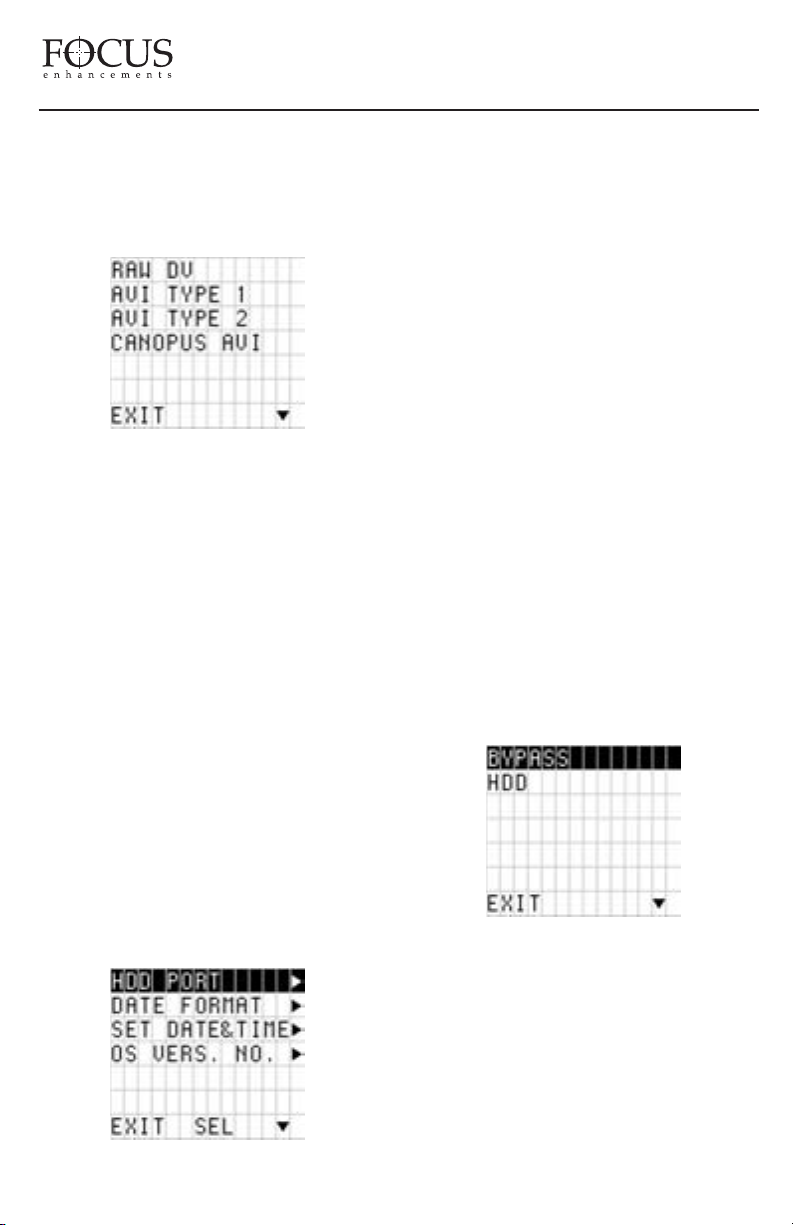
FireStore DR-DV5000 User Guide
Be sure to properly dismount the FireWire drive
from the computer system first before exiting
HDD Bypass mode on DR-DV5000.
RECORD FORMAT MENU
The RECORD FORMAT menu allows selection
of particular DTE Technology native NLE file
format prior to recording. All files are in the
DV25 standard.
Available items in the RECORD FORMAT
MENU are:
RAWDV
AVI TYPE 1
AVI TYPE 2
CANOPUS AVI
MATROX AVI
QUICKTIME
AVID OMF
The SETUP MENU allows various functions of
DR-DV5000 to be set. User simply selects the
Setup Item. Pressing SEL will open the sub
menu. Pressing EXIT will exit back to the
menu screen. Unless mentioned, the particular
setup menu will stay set until user selects a
different setting (even if the power is cycled).
Available items in the SETUP MENU are:
HDD PORT
DATE FORMAT
SET DATE&TIME
OS VERSION NO.
OS UPGRADE
CAM TYPE
TC MODE
TC SET
IR
GPI
BACK LIGHT
CLIP PREVIEW
AUDIO CORRECT
DV BYPASS
FOLDER PREF
ort
HDD P
User simply selects the format. Highlighted
format is current format after exit. Pressing
EXIT will exit back to the menu screen.
Selected format will stay set until user selects a
different format (even if the power is cycled).
SETUP MENU
PAGE 25
The HDD Port setting allows the user to assign
a function to the DR-DV5000 “HDD I/O” port.
BYPASS mode is for making the internal disk
drive available to an external device (such as a
computer). HDD Mode is used when the “HDD
I/O” port is used for connecting external
FireWire disk drives. Pressing EXIT will exit
back to the menu screen.
Page 27
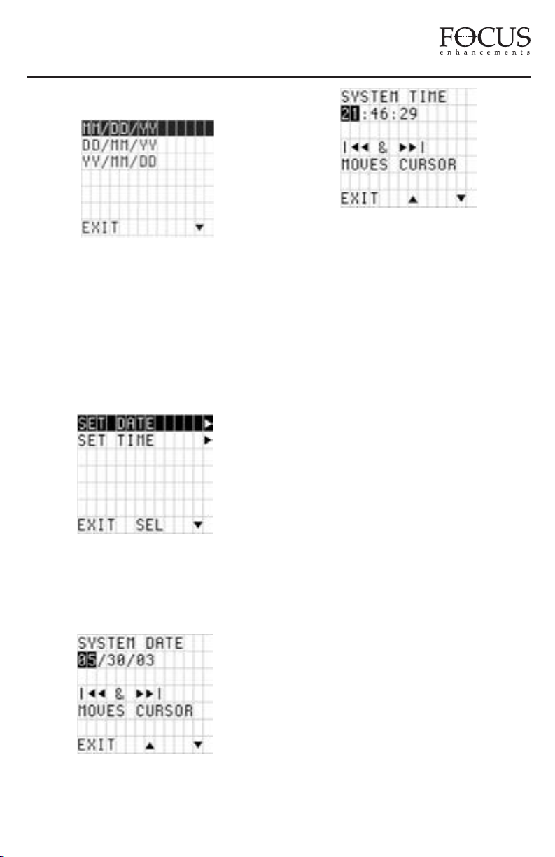
FireStore DR-DV5000 User Guide
Date Format
Allows user to select the different display
options for date on the DR-DV5000 LCD.
Setting only affects the LCD display. File
name will always remain YYYYMMDDHHMMSS.xxx (Year-Month-Date-HourMinute-Second). Pressing EXIT will exit
back to the menu screen.
Set Date and Time
Scroll from value to value using the FORWARD
and BACK INDEX Buttons. Press DOWN and
UP arrow to scroll though digits in value.
Pressing EXIT will exit back to the menu
screen. Regardless of display, file name will
always remain YYYYMMDD-HHMMSS.xxx
(Year-Month-Date-Hour-Minute-Second). User
simply selects the Menu Item. Pressing SEL
will open the sub menu. Pressing EXIT will
exit back to the menu screen.
The Date and Tme form the basis of the DRDV5000 file naming structure for use of clips
on a computer.
On DR-DV5000, files are identified by TRACK
and VOLUME (disk drive) number on the LCD.
For instance, a file on the DR-DV5000 LCD
identified as 1-043 is clip number 43 on
Volume (disk) 1.
Allows for setting date and time for file naming
poses. Date and Time are set in different
pur
menus. Pressing the SEL b
utton will open the
sub menus.
On a computer, files are identified by their base
file name made up of DATE and TIME. For
instance, a clip named 20030615-210943-
01.mov is a clip that began recording at
9:09:43PM on June 15th. 2003.
NOTE: DATE/TIME is used when creating File
name only. DR-DV5000 does not record this
information into the stream. DR-DV5000
records DATE/TIME which is in the DV stream
which is sent from the camcorder.
PAGE 26
Page 28
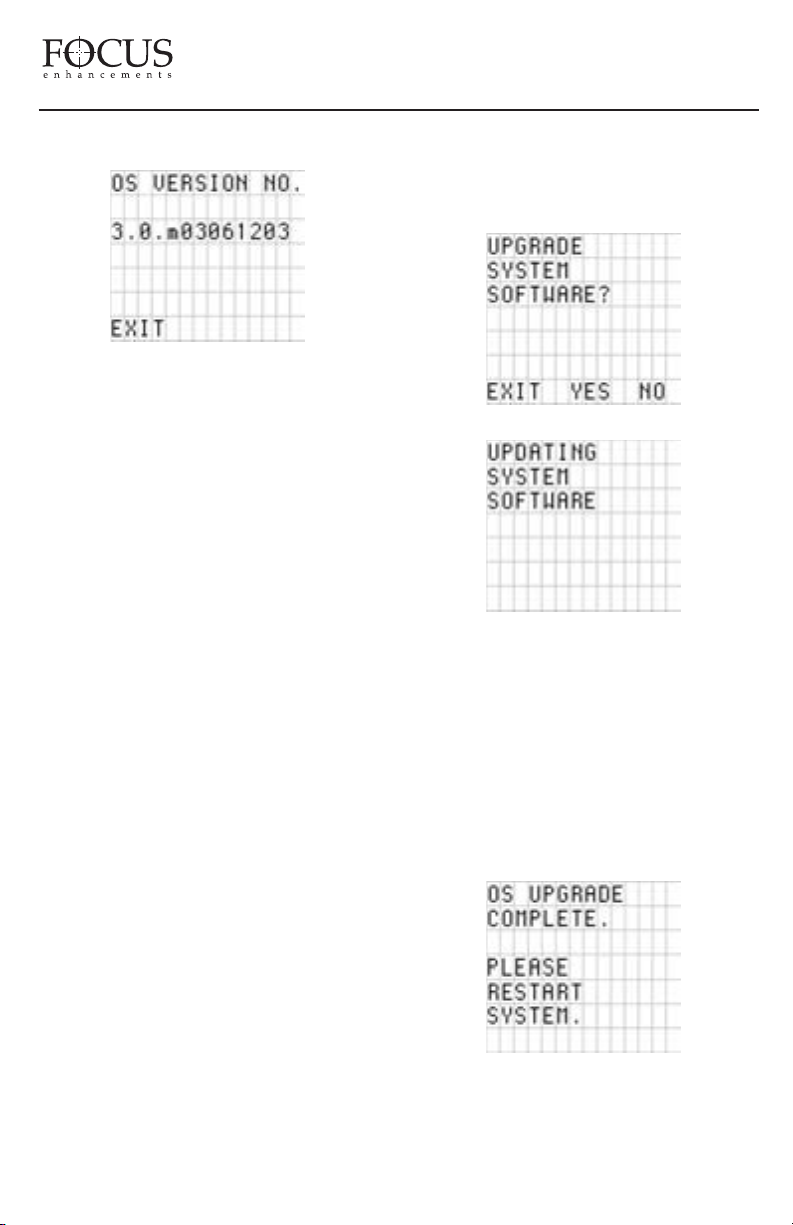
FireStore DR-DV5000 User Guide
Operating System Version No.
Displays the current system software version.
Operating System Upgrade
To upgrade system software, the user must
download a new .bin file to a FireWire drive on
their computer. The latest version of DRDV5000 software can be downloaded from
http://www.focusinfo.com/support .
To install new OS software to DR-DV5000,
do the following:
1) Download software from the Focus Website
to your local computer.
2) Unzip file using WinZip (Windows) or
Stuffit (Macintosh) on a computer system with
a FireWire (IEEE-1394) connection.
3) Rename the unzipped file called
“XXXX.bin” to “dr-dv5k.bin”.
4) Connect a FireWire disk drive that has been
used with DR-DV5000 to the computer and
copy over the file “dr-dv5k.bin”.
7) When prompted “DO YOU WANT TO
UPGRADE SYSTEM SOFTWARE?” answer
YES and YES to the erase current OS!!
Upgrade will begin.
8) After upgrade is complete, power cycle
DR-DV5000. The new software should now
be loaded and ready to use.
NOTE: If you need to restore the factory
default Operating System, hold down the
Forward and Backward Index keys during boot
up. If no .bin file is found, the screen will
display “OS UPGRADE ERROR”. It is
necessary to restart your system once an OS
upgrade is complete.
5) Disconnect F
and connect to DR-D
V5000 as per normal.
D
ireWire drive from computer
V5000. Power on DR-
6) Enter the DR-DV5000 menu and select
“SETUP”. From the SETUP menu, select “OS
UPGRADE”.
PAGE 27
Page 29
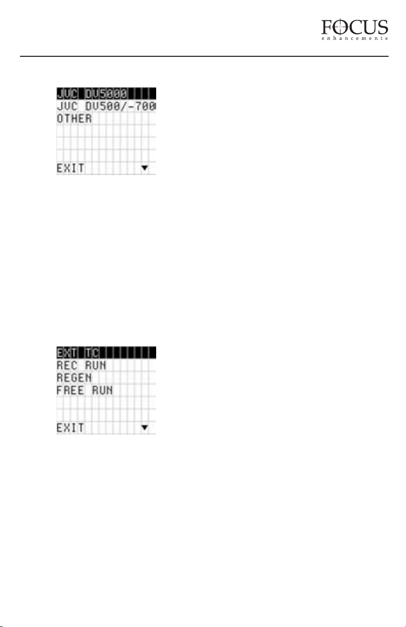
FireStore DR-DV5000 User Guide
Cam Type
User simply selects the camcorder they will be
using with DR-DV5000. This will load a
preference for that particular model. The
highlighted item is the current camcorder after
exit. Pressing EXIT will exit back to the menu
screen. Selecting JVC DV5000 or 500/-700 will
set Timecode preference to SMPTE Timecode.
Selecting OTHER will set Timecode preference
to DV Timecode. Selecting JVC DV500/-700
disables some features that are specific to
operation with a JVC GY-DV5000 camcorder.
Timecode Mode
mode will clear any stored number.
NOTE: If DR-DV5000 is set to EXT TC when
in SYNCRO SLAVE mode, EXT TC will stop
once tape in GY-DV5000 ends. Use different TC
mode when using SYNCRO SLAVE. (TC Preset
cannot be changed while in the EXT TC mode.)
REC RUN Mode - In this mode, DR-DV5000
does the following:
(1) the last timecode number recorded + 1 will
be used as the timecode number for the first
frame of the next recording.
(2) the number entered by a setting in the TC
PRESET menu will be used for the first frame
of the next recording. The last number used is
stored in the memory, so this mode persists
across recording sessions.
REGEN Mode - After a disk is mounted(at
startup, upon manual connect) and after the track
list has been constructed, DR-DV5000 looks at
the last track and looks at the timecode number
of the last frame in that track. DR-DV5000
stores that number for use as the TC value (+ 1)
for the first frame of the next recording.
ws user to select different timecode options
Allo
for use when DR-DV5000 is recording. User
simply selects the mode. Highlighted mode is
current mode after exit. Pressing EXIT will exit
back to the menu screen.
EXT TC Mode - Whatever the incoming
DV timecode, DR-DV5000 records it. If
the Camcorder TC is not running, and DRDV5000 is recording, the same TC number will
be in each frame of DV. Choosing EXT TC
If the drive is empty, DR-DV5000 uses the
value (+ 1) stored in memory.
FREE RUN Mode - When the user enables
FREE RUN mode, DR-DV5000 begins
counting from the v
TC PRESET function, w
the
entered and the
V5000 be
DR-D
alue stored. If the user uses
hen the number is
TC PRESET menu is e
gins counting.
xited,
NOTE: When the DR-DV5000 timecode mode is
set to EXT TC and the camcorder time code
mode is set to PRST/REC or REGEN, it is not
le to record timecode continuously when
possib
recording to disk onl
y. Set the DR-DV5000
timecode mode to REGEN, REC RUN or FREE
RUN (not EXT TC) when recording to disk only.
PAGE 28
Page 30
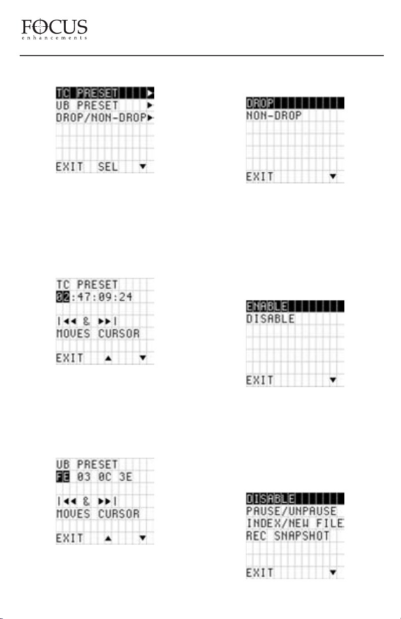
FireStore DR-DV5000 User Guide
Timecode, UserBit and Drop/Non-Drop Preset
This menu allows the user to set timecode and
user bit values for various modes. It also allows
selection of drop or non-drop frame (NTSC
only) settings. User simply selects the Menu
Item. Pressing SEL will open the sub menu.
Pressing EXIT will exit back to the menu screen.
value selection to value selection. Press the up
and down arrows to set values.
For DROP and NON-DROP, user simply selects
the mode. Highlighted mode is current mode after
exit. Pressing EXIT will exit back to the menu
screen. This item not applicable for PAL use. On
the DR-DV5000 display, DROP will be identified
by a (.) symbol and NON-DROP by a (:) symbol.
Infrared Sensor Settings
Once a timecode value is set and DR-DV5000 is
set to REC RUN or FREE RUN timecode settings,
the preset value will be the starting point for
timecode. Use the forw
ve from value selection to value selection.
to mo
Press the up and do
ard and back index buttons
wn arrows to set values.
Allows the user to set a user bit value. Use the
forward and back index buttons to move from
PAGE 29
This menu allows the user to ENABLE or
DISABLE the IR sensor on DR-DV5000. User
simply selects the Menu Item. Highlighted
mode is current mode after exit. Pressing EXIT
will exit back to the menu screen.
GPI Settings
Page 31
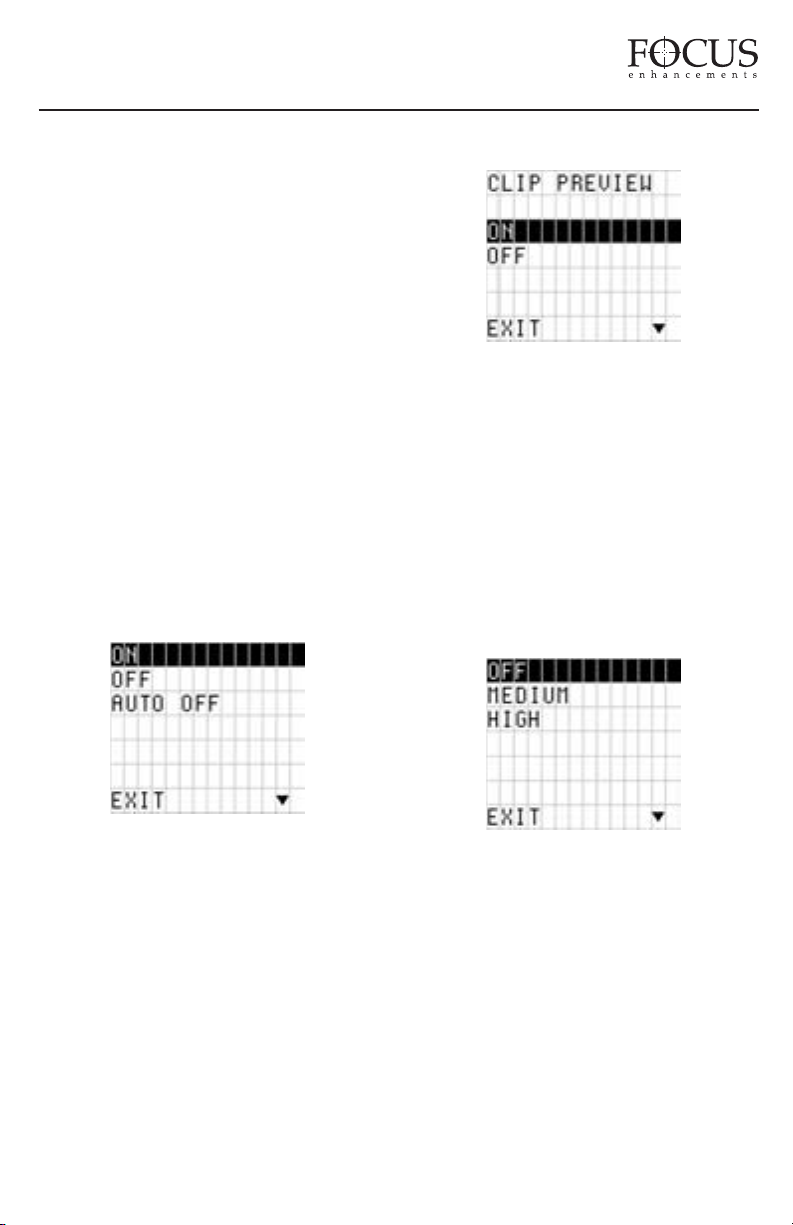
FireStore DR-DV5000 User Guide
This menu allows the user to change the setting
of the GPI port. User simply selects the Mode.
Highlighted mode is current mode after exit.
Pressing EXIT will exit back to the menu
screen.
DISABLE allows user to connect the supplied
3.5mm to DB9 cable to the GPI port and
control DR-DV5000 via RS232C from an
external device.
The remaining three items allow functions to
occur from a simple contact closure. Modes are
PAUSE/UNPAUSE (allows control of pause and
unpause during a record or playback session),
INDEX (NEW FILE) (allows a new file to be
created during a record session without losing
any frames) and REC SNAPSHOT (allows a
single frame of video to be recorded to a file.
Each sequential trigger in this mode will add
another frame to the same file until stopped).
LCD Backlight Settings
Clip Preview Settings
This menu allows the user to select CLIP
PREVIEW ON or OFF. When CLIP PREVIEW
is ON, the camcorder is in VTR mode and the
user scrolls from one clip to the next on DRDV5000 using the buttons, the first frame of each
clip will be generated and showed via DV output
after one second if the user pauses on that clip.
User simply selects the Mode. Highlighted
mode is current mode after exit. Pressing EXIT
will exit back to the menu screen.
Audio Correction Settings
This menu allows the user to enable or disable
the DR-DV5000 LCD back-light. Highlighted
state is current after exit. Pressing EXIT will
exit back to the menu screen.
The ON setting will keep the back-light on
permanently while the OFF setting will keep
the back-light off permanently. AUTO OFF will
turn off the back light after one minute.
Pressing any keypad button on DR-DV5000
will turn the back-light back on in AUTO OFF
state. This setting is advisable in high
temperature environments and also to reduce
power consumption.
This menu allows the user to change the AUDIO
CORRECTION setting on DR-DV5000. User
y selects the Mode. Pressing EXIT will
simpl
xit back to the menu screen.
e
AUDIO CORRECTION modes is an advanced
feature of DR-DV5000. It is recommended that the
customer uses the factory default settings for most
operations (F
rection Mode allows the user to alter the
Cor
perfor
recording. It is useful w
actory default is MEDIUM). Audio
mance of the audio error corrector while
hen recording to DRDV5000 from tapes with lots of dropouts. Error
correction will only effect AVI 2, Canopus AVI,
PAGE 30
Page 32
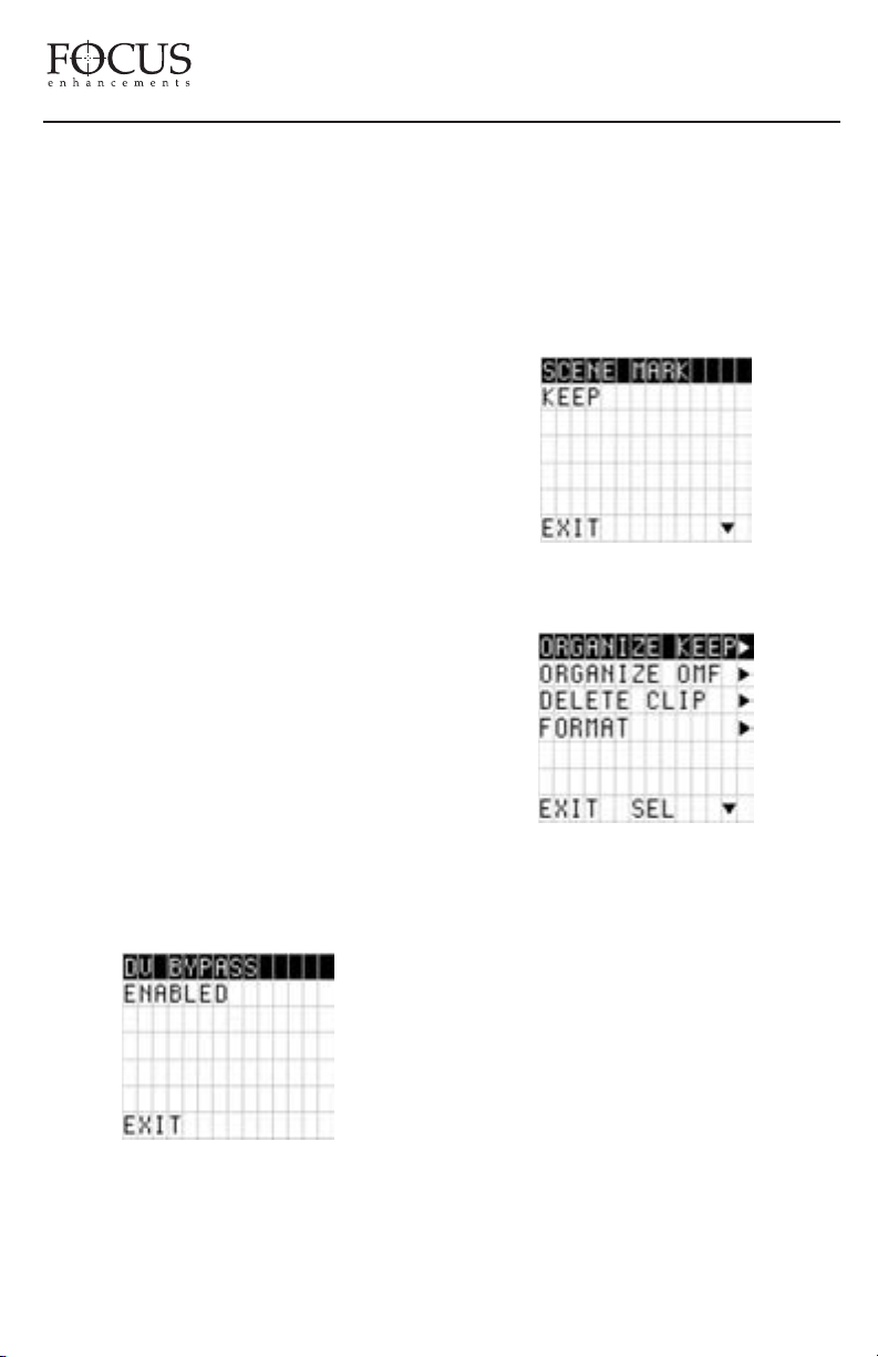
FireStore DR-DV5000 User Guide
Matrox AVI, QuickTime and AVID OMF. It does
not effect RawDV or AVI 1. The modes are:
OFF - No audio correction.
MEDIUM (default) - For “normal” clean tape
played back on GY-DV5000 camcorder or other
VTR with clean heads. Experiences occasional
very short audio mutes.
HIGH - For cases where there are visible
picture disturbances and likely long audio
dropouts (1/2 sec and up).
DV Bypass
When using a JVC GY-DV5000 camcorder
(such as the GY-DV5000U(A) that has been
modified for DV I/O via the 52-pin connector,
DV Bypass allows DR-DV5000 to act simply
as a pass through or bypass between the
camcorder and external devices such as NLE
systems. External devices can be connected to
the DR-DV5000 DV I/O connector. To enable
DV Bypass, simply scroll to DV BYPASS in
the SETUP MENU and press the SEL button.
The DR-DV5000 display will display "DV
BYPASS ENABLED". To exit this mode,
simply press the EXIT button.
Folder Pref
The DR-DV5000 FOLDER PREFERENCE
allows use of a single KEEPER folder or
multiple SCENE MARKING folders. The
highlighted preference is selected on EXIT. See
SCENE MARKING section on page 35 of this
User Guide for more details.
UTILITIES MENU
Consult with JVC or your JVC
dealer/distributor for more information on your
-DV5000 model.
GY
PAGE 31
The UTILITIES MENU allows various utility
functions of DR-DV5000 to be set. User simply
selects the Utilities Item. Pressing SEL will
open the sub menu. Pressing EXIT will e
xit
back to the menu screen.
vailable items in the UTILITIES MENU are:
A
ORGANIZE FOLD
ORGANIZE OMF
DELETE CLIP
FORMAT
PARTITION
REPAIR
FILE NAME
FACTORY RESET
Page 33
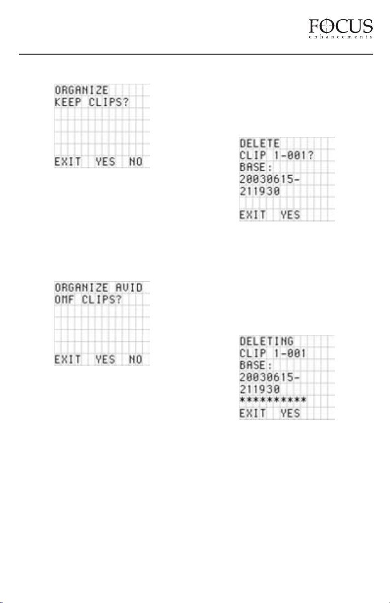
FireStore DR-DV5000 User Guide
Organize Folders
Places all files that were identified as a
KEEPER or were SCENE MARKED during
recording into a folder marked KEEPER or the
prenamed SCENE MARKING folders on the
disk drive. These folders can be imported
directly into most DV NLE bins.
Organize OMF
clips in KEEPER or SCENE MARKED folders
in Avid, manually create the “OMFI MediaFiles”
folder when your disk drive is on your computer
and drag desired clips into this folder.
Delete Clip
With this function, it is possible to delete the
selected clip. In the DELETE CLIP X-XXX
screen, user can select between clips by
pressing the forward and back index buttons.
Pressing SEL will begin the delete process.
Pressing EXIT will exit back to the menu screen.
NOTE: FOCUS recommends not deleting clips
frequently. It may cause fragmentation.
When files are recorded in the AVID OMF file
format, this command automatically takes all
the OMF and
AIF audio files at the end of a
recording session and places them into a folder
on the disk dri
When the disk is connected to a computer
ve named “OMFI MediaFiles”.
, this
folder is recognized by Avid’s Media Tool
feature enabling direct import of files into the
Avid timeline.
NOTE: If you have selected files as a KEEPER
or they have been SCENE MARKED, It is not
possible to use this feature and keep files in
their selected folders. If you would like to use
Once a clip has been deleted, the DR-DV5000
display re-organizes the clip number sequence.
For instance, if there are three clips on disk (1001, 1-002, 1-003) and the user deletes clip 1002, after delete is complete, clip 1-003 will
become clip 1-002. Base file names are not
affected however.
PAGE 32
Page 34
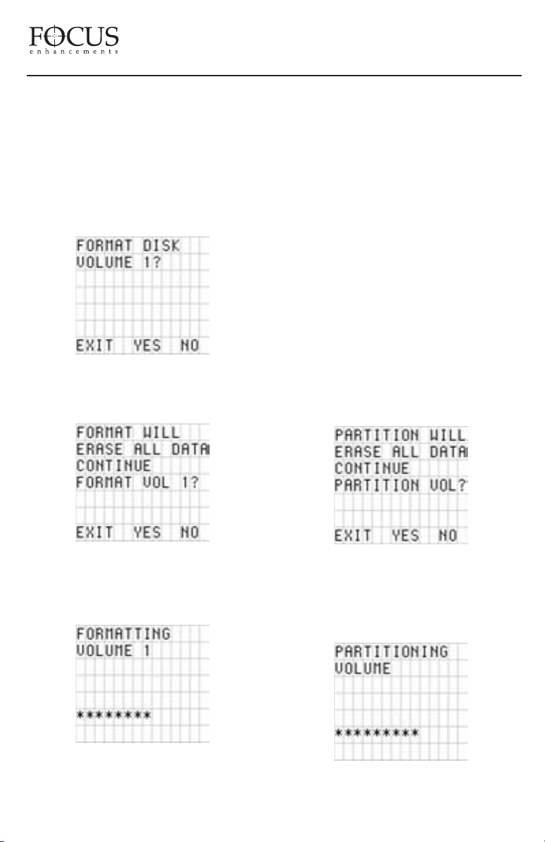
FireStore DR-DV5000 User Guide
Format Disk
With this function, it is possible for the user to
format a disk. It is recommended that this is done
after each record session to prevent fragmentation
and other problems with the disk drive.
WARNING: FORMAT ERASES ALL DATA
ON THE DISK DRIVE!
To exit from format, press either NO or EXIT.
To continue with format, press the YES key.
FireStore DR-DV5000 utilizes a FAT32 format
type. If you are using a non-FAT32 formatted
drive, see the section on Partitioning a volume.
Once complete, the disk drive is ready for use
with DR-DV5000. It is advised that the drive be
formatted before a new record session is begun.
After a format is complete, ten file folders are
added to the disk drive (numbered 0-9). These
folders are utilized in the SCENE MARKING
feature (see page 35 of this User's Guide for
details).
DESKT
Also added to the disk is a LOG folder, a
OP folder and two additional files called
Desktop DB and Desktop DF. Do not delete these
files as they are required for FireStore operation.
Partition Volume
When an unknown or blank volume type (HDD)
is connected to DR-DV5000, the Partition
process puts a FAT32 format onto the drive. It
will erase any previous partition and data.
To exit from the warning screen, press either
NO or EXIT. To begin the format, press the
YES key.
PAGE 33
To exit from partition, press either NO or EXIT.
o continue with partition, press the YES key.
T
WARNING: PARTITION ERASES ALL DATA
ON THE DISK DRIVE!
Page 35
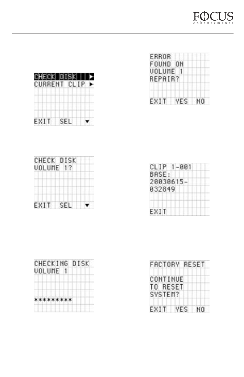
FireStore DR-DV5000 User Guide
Once complete, the disk drive is ready for use
with DR-DV5000.
Repair Disk
REPAIR allows the user to select either
CHECK DISK or CURRENT CLIP.
moments to complete in most cases.
CURRENT CLIP does a similar function, but
on the selected clip only. If an error is found,
DR-DV5000 will prompt the user to repair
the problem.
File Name
CHECK DISK scans the entire volume for any
errors (usually, if a disk was corrupted during a
recording due to sudden power loss, check disk
will alert the user of this). To exit check disk,
press either NO or EXIT.
If an error is found, the user will be prompted
to repair the file. File repair only takes a few
File Name displays the base file name of the
selected clip.
Factory Reset
When this function is selected, DR-DV5000 will
revert all settings and values back to their factory
PAGE 34
Page 36
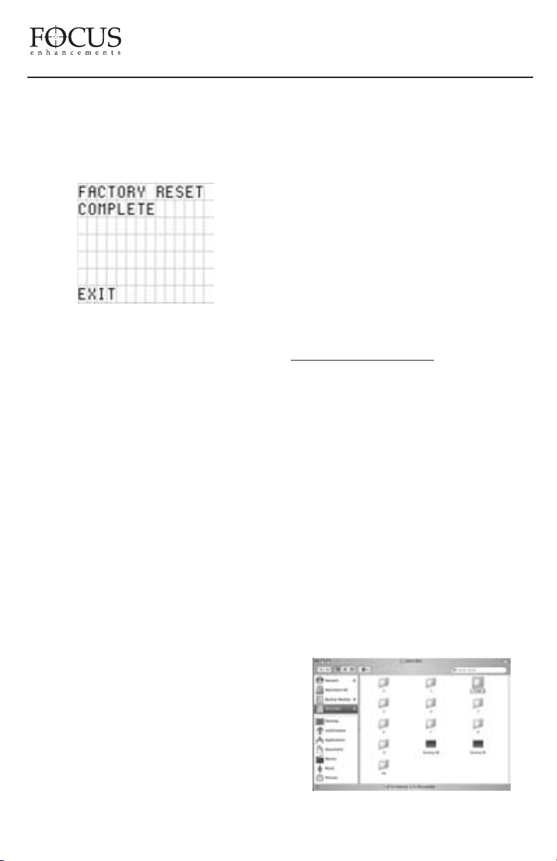
FireStore DR-DV5000 User Guide
default state. Pressing YES will start factory
reset. Pressing EXIT or NO will exit from menu.
Warning: Factory Reset is not un-doable!!!
The following screen will display when complete:
After factory reset is complete, please restart
DR-DV5000
Factory Default States Are as Follows:
Display:
• COUNTER
Rec Mode:
• DEFAULT REC MODE: NORMAL
• RETRO DISK – RETRO VALUE -> 000min
• RETRO CACHE – CACHE ->00 sec
• TIME LAPSE –> 00:00:00:00
Play Mode:
• DEFAULT PLAY MODE: PLAY CLIP
• DEFAULT PLAY FROM MODE:
TRACK LIST
Play From:
• DEFAULT PLAY FROM MODE:
TRACK LIST
Control Mode:
• DEFAULT CONTROL MODE: LOCAL
• SERIES REC -> OFF
Rec Format:
• DEFAULT REC FORMAT: AVI TYPE 2
Setup:
• HDD PORT -> HDD
• DATE FORMAT -> MM/DD/YY
• SET DATE&TIME :
• DATE: 07/24/03
• TIME: 12:00:00
• OS VERSION NO. -> VARIABLE
• CAM TYPE -> JVC DV5000
• TC MODE -> EXT TC
• TC SET:
• TC PRESET -> 00:00:00:00
• UB PRESET -> 00 00 00 00
• DROP/NON-DROP -> NON-DROP
• IR -> ENABLE
• GPI -> DISABLE
• BACKLIGHT -> ON
• CLIP PREVIEW -> PREVIEW ON
• AUDIO CORRECTION -> MEDIUM
USING SCENE MARKING
The FireStore DR-DV5000 SCENE MARKING
feature allows clips to be marked for placement in
particular folders during recording, playback or
stop mode. When a drive is formatted using
FireStore, ten folders will be created numbered 0
through 9. After format on FireStore, it is possible
to connect the HDD to a computer and give each
of these folders a custom name (if you need help
mounting your FireWire HDD to your computer
system, see section titled "Getting FireStore
Recorded Clips onto a Computer" on page 36 of
this User's Guide). To rename each folder, simply
click on the folder name until it is highlighted, then
type in the desired name of the folder.
NOTE: Folder names cannot exceed eleven
characters.
PAGE 35
Page 37
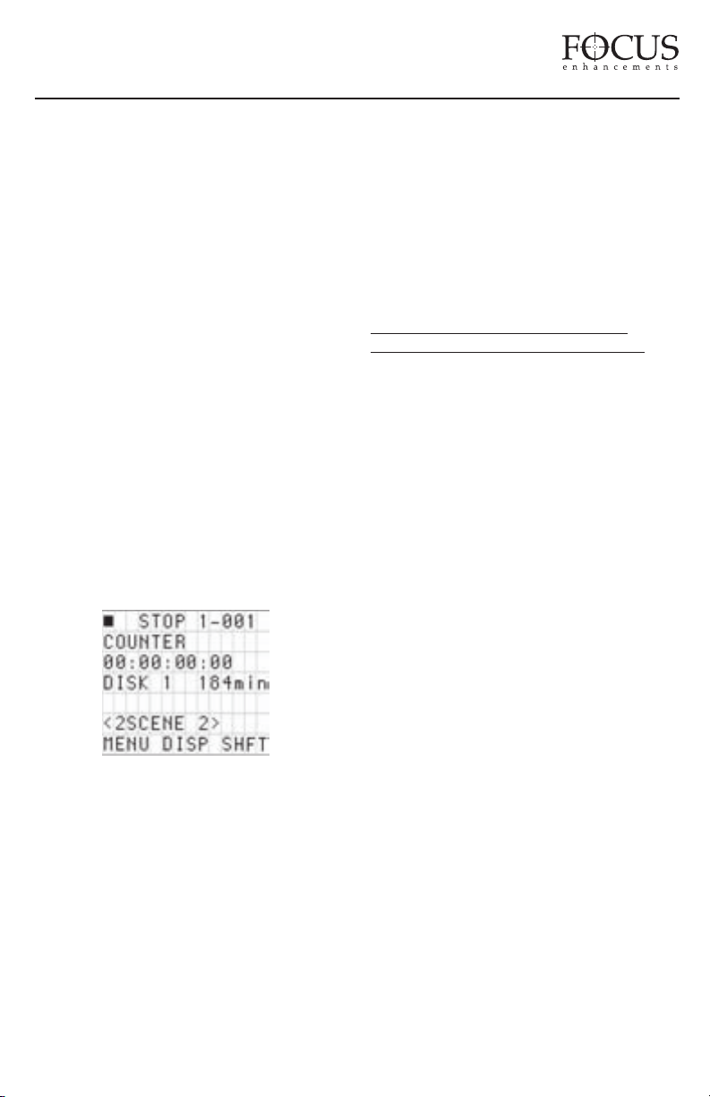
FireStore DR-DV5000 User Guide
Folders will be ordered on FireStore in
numerical followed by alphabetical order. For
instance, if folders are named “Scene 1”,
“Scene 2” and “Auditions”, they will appear on
FireStore as “1 Auditions”, “2 Scene 1” and “2
Scene 2”. The folder number is added in front
of the folder name on the FS-3 LCD display for
easy identification when using the optional
remote control commander keypads. If you
would like to create a custom order to Folders,
it is recommended that you change the name to
change the numerical /alphabetical order.
To use SCENE MARKING, it is necessary to
first enable the SCENE MARK setting under
FOLDER PREFs in the SETUP menu. Once
you have selected the SCENE MARK
preference, pressing and holding Soft Key (3)
followed by Soft Key (2) allows you to mark
each clip into the selected, prenamed folder on
disk. By holding Soft Key (3) down and
repeatedly pressing Soft Key (2), it is possible
to scroll though the available folders. Each
SCENE MARK FOLDER is shown on the DRDV5000 LCD display.
If the DR-D
V5000 PLA
Y MENU is set to
"TRACKLIST" the name of the SCENE
MARKED folder will appear without brackets
on the LCD display (e.g. 2 DEFENSE). If the
PLAY FROM menu is set to "FOLDERS", the
name of the SCENE MARKED folder will
appear in brackets on the LCD display (e.g. 2
<DEFENSE>).
It is also possible to SCENE MARK clips to
folders using the numeric keypad on the
supplied remote control units (see page 40 of
this User Guide for more infor
mation). To add
all SCENE MARKED clips to their respective
folders on the disk drive, select UTILITIES ->
ORGANIZE FOLD from the DR-DV5000
menu and answer yes to "Organize Clips". Once
complete, an additional file is added to the disk
named "grade" and files are moved to the
selected folder for easy access on an NLE
system. Do not delete the file named "grade"
from the disk if you intend to use the disk on
FireStore again.
GETTING FIRESTORE RECORDED
CLIPS ONTO A COMPUTER SYSTEM
Once you have recorded clips to your FireWire
disk drive using FireStore, it is possible to use
those clips in most computer based DV NLE
systems.
Traditionally, in order to get footage into your
NLE system, it was necessary to capture or
digitize that footage utilizing a video capture
card. Using FireStore DR-DV5000 recorded
clips, it is possible to skip this capture stage by
simply connecting the FireWire disk drive to
your computer via an OHCI compliant IEEE1394 (FireWire) PCI card or connection.
FireWire disk drives that were used with
FireStore DR-DV5000 can be connected to any
computer system that will read a FAT 32
volume. This includes Windows 98SE,
Windows ME, Windows 2000, Windows XP
and Mac OS9 and OS10. FAT32 volumes will
not work with Windows NT and older
Macintosh based operating systems. Check the
FOCUS Enhancements’ website
(www.FOCUSinfo.com) for more information.
In order for y
recorded F
ou must have an active IEEE-1394 connection
y
our computer. You also must have loaded
on y
y required FireWire disk drive drivers onto
an
our computer system (Consult y
y
disk dri
Simpl
ou to use FireStore DR-DV5000
ireWire disk drives on a computer,
our FireWire
ve documentation for more information).
y connect your FireWire disk drive to
your computer system utilizing a standard 6-pin
to 6-pin FireWire cable and connect power to
PAGE 36
Page 38
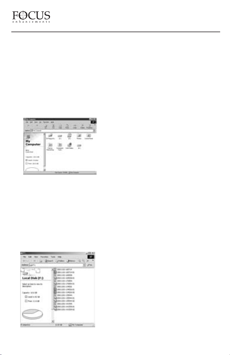
FireStore DR-DV5000 User Guide
the drive if necessary (some FireWire disk
drives receive power from the computer’s
FireWire connection. Consult your FireWire
disk drive documentation for more information).
Mounting FireWire Disk Drives to Windows
XP, 2000, 98SE and ME Computer Systems
On a Windows based computer system, simply
double click the My Computer icon on the top
left hand corner of the desktop. You will see the
following window:
Locate your FireWire disk drive. This will
probably be labeled (E:), (F:), (G:) etc. (drive C:
is usually your computer’s main disk drive).
Once located, double click on the FireWire disk
drive. (If you have trouble locating the FireWire
disk drive, right mouse click each drive and
select Properties from the menu. Click the
Hardware tab which will list the drive type).
Once opened, you should see the following window:
The FireWire disk drive contains several
different files. Clips can appear as RawDV
(.dv), AVI Type 1 (YYYYMMDDHHMMSSa01), AVI Type 2 (YYYYMMDDHHMMSSb01), Canopus AVI (YYYYMMDDHHMMSSb01), Matrox AVI (YYYYMMDDHHMMSSm01 with a separate .wav audio file
per track), QuickTime (.mov) and Avid OMF
(.omf with two separate .aif audio files per
track.).The FAT32 file system has a limitation
where any particular file cannot exceed 2GB in
size. This equates to roughly 9 minutes of
recording time. When clips are being recorded
to FireStore that exceed 9 minutes in length,
FireStore automatically creates a new file
without dropping any frames. The two clips will
have the same primary file name, however, the
last tow digits will be different. The first 2GB
part of the clip will be labeled with “-01” after
the primary file name. The second 2GB
segment will be labeled with a “-02”.
Additional 2GB segments will be labeled with a
“-0X” number. With most NLE systems on a
Windows computer, it is possible to utilize clips
within the timeline simply by selecting the clips
on the source v
connected F
olume (in this case, the
ireWire disk drive) and importing
them directly into the NLE’s bin. Clips can then
be immediately used in the NLE’s timeline.
With FireWire disk drives such as the FireStore
FSHDD-1, the drive itself is fast enough to
directly stream the clips to the NLE eliminating
the need to copy or transfer the clips before use.
When utilizing the Avid OMF file format, it is
necessary to follow the following steps to
import clips.
PAGE 37
e DR-DV5000 recorded Avid
Using Fir
OMF clips on
eStor
vid NLE systems.
A
The Avid DV OMF file format was developed
for use with Avid Xpress DV version 3.0 or
latter on Windows 2000, Windows XP or Mac
0S10. FireStore OMF clips are also compatible
with certain NewsCutter, Xpress Pro and Media
Composer systems. Check the Focus Website
for an up to date list. The Avid DV OMF file
mat creates three files simultaneously; an
for
Page 39
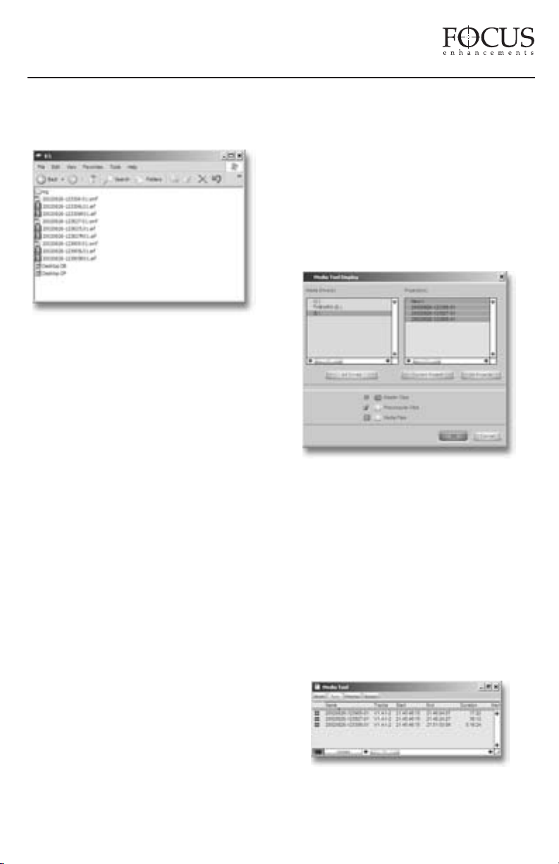
FireStore DR-DV5000 User Guide
OMF video file and two separate AIF audio
files. On the computer’s desktop, the files will
look like this...
On the FireStore DR-DV5000, the video file
(OMF) and the audio files (AIF) appear as one
track. If you delete an Avid DV OMF file,
FireStore will delete the audio and video portions
at the same time.
In order to use the FireStore DR-DV5000 recorded
Avid DV OMF files on your Avid system from the
external FireWire drive, you must do the following…
1. Locate the external FireWire drive on your
computer. (If you have trouble, you can locate the
name of the external drive by selecting
My
Computer on a Windows system. On a Mac, the
FireWire drive should appear on the desktop).
2. Open the FireWire drive when you have found it
and create a new folder named “OMFI
MediaFiles”. To do this on Windows, select
File ->
New -> Folder from the pull down menu. On Mac,
ile -> Ne
F
select
“OMFI MediaF
vid to see the disk dri
A
iles into the ne
AIF f
w Folder
. It is impor
iles” is typed cor
rectly in order for
ve. Drag all the OMF and
w folder (do not drag in the
tant that
files titled Desktop DB or Desktop DF).
been SCENE MARKED, it is not possible to
use this feature and keep files in their selected
folders. If you would like to use clips in
KEEPER or SCENE MARKED folders in Avid,
manually create the "OMFI MediaFiles" folder
when your disk drive is on your computer and
drag desired clips into this folder.
3. Launch Avid. Once you have opened the desired
project or created a new project, select
Tools ->
MediaTool. The following window will appear:
4. Locate and select the external FireWire drive
under Media Drive(s).
NOTE: If the drive does not appear, check that
you have created the OMFI MediaFiles folder
correctly with proper case and spacing. Also,
check to see that the drive is properly connected
and recognized by the computer.
Under Project(s), select All Projects (This will
highlight all items in the Project(s) window).
Master Clips is checked then press OK.
Ensure
The following Media Tools Window will appear:
NOTE: if you are using the ORGANIZE OMF
function on DR-DV5000 prior to using the disk
on a computer, step 2 is not necessary. If you
have selected files as a KEEPER or they have
PAGE 38
Page 40
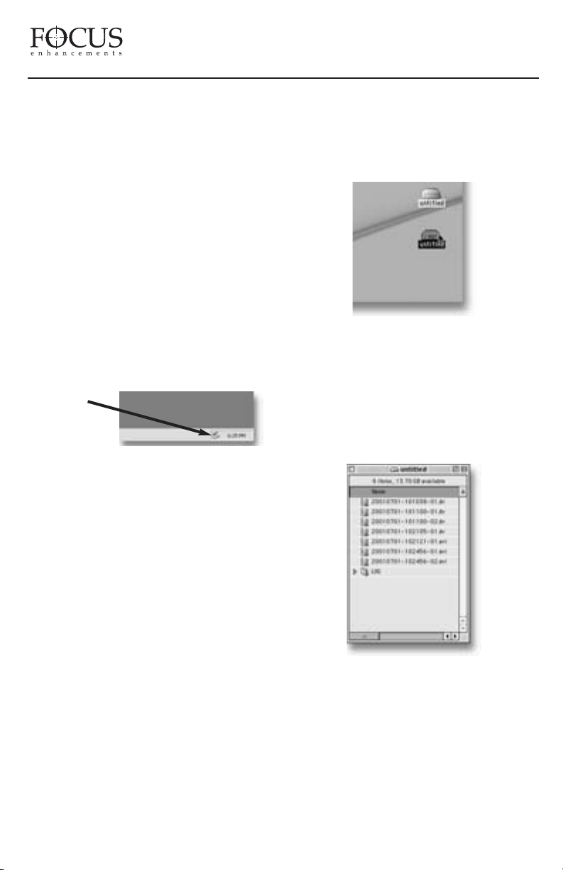
FireStore DR-DV5000 User Guide
5. Create a new bin (select File -> New Bin) or
open an existing bin in Avid. Once opened, select
all items in the Media Tools window (select
Select All). Drag the contents of the Media Tools
Window into the bin. It is now possible to use
these clips in the Avid timeline.
Dismounting FireWire Disk Drives
from Windows XP, 2000, 98SE and ME
Computer Systems
Once you have completed working with your
disk drive on a Windows XP, Windows 2000,
Windows 98SE or Windows ME computer
system, you must first dismount the drive
before unplugging it. To do this, simply click
on the Stop Device icon at the bottom right side
of the Windows task bar. See Below:
Edit->
The Windows
“STOP
DEVICE”
Icon
Once clicked, your computer system will prompt
you to “STOP” the connected FireWire disk drive.
This will begin the dismount process. Select the
message by clicking on it. The computer will now
dismount the disk drive and notify you when it is
safe to remove the volume.
FireWire disk drive drivers have also been loaded
onto you computer system (consult your FireWire
disk drive’s documentation for more information).
When mounted, your FireWire disk drive should
appear on the computer’s desktop:
The FireStore formatted disk drive will appear as a
FAT32 volume and hence have a PC label. This is
not always the case on OS10 however.
Once you have located your FireWire disk drive on
the desktop, double click the disk icon to open it
up. Once opened, you will see the following:
Mounting FireWire Disk Drives to
Macintosh Computer Systems
NOTE: Even if your FireWire disk drive was
bought for use on a Macintosh, you MUST first
format the drive as a FAT 32 volume on a
Windows based computer system for it to work
with FireStore.
On a Macintosh, start your computer and simply
connect your FireWire disk drive to the computer
utilizing a standard 6-pin to 6-pin FireWire cable.
Consult your FireWire disk drive documentation
for more information. Ensure the required
PAGE 39
Dismounting FireWire Disk Drives from
Macintosh Computer Systems
Once you have completed working with your disk
drive on a Macintosh computer system, you must
first dismount the drive before unplugging it. To
do this, simply select the disk drive on the
Page 41
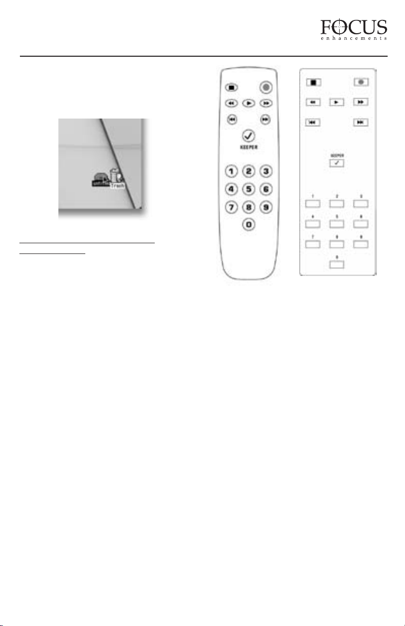
FireStore DR-DV5000 User Guide
computer’s desktop. It will be marked with a PC
symbol. Once selected, drag the drive into the
trash. This will then dismount the particular disk
drive. See Below:
DR-DV5000 REMO
COMMANDERS
Two remote control commanders came with
your DR-DV5000. One is an infrared
commander made for use with the infrared
remote sensor on the DR-DV5000 front panel
and the other features a 3.5mm, 15ft. cable for
use when infrared is not an option.
Before using your infrared remote commander,
ensure you have batteries installed in the unit (2
x AAA) and that the IR sensor is enabled (see
page 29 for details).
Before using the wired remote control
commander, ensure you have securely inserted
the 3.5mm mini jack to the CONTROL port on
the DR-DV5000 rear connector panel. You will
also require batteries to use this unit (2 x
AAA).
The DR-D
commanders ha
Buttons ha
similar DR-D
where noted. Remote buttons do not feature a
hold to repeat function like the front panel.
Multiple triggers must be repeatedly pressed.
They both feature the following keys
V5000 wired and infrared remote
ve the same functionality as the
TE CONTROL
ve the same functionality.
V5000 front panel buttons except
Wired Remote
Commander
Keypad Layout
The DR-DV5000 wired and infrared remote
commanders have the same functionality. They
both feature the following keys:
STOP
RECORD
BACKWARD SEARCH
FORWARD SEARCH
PLAY
BACK INDEX
FORWARD INDEX
KEEPER -this is the same as the KEEPER
function on the DR-DV5000 front panel.
NUMERIC KEYPAD (0-9): when using the
SCENE MARKING feature, use these keys to
mark clips to folders 0-9 (these may be
prenamed folders - see section 35 for details)
during record, playback or stop modes.
Infrared Remote
Commander
Keypad Layout
PAGE 40
Page 42
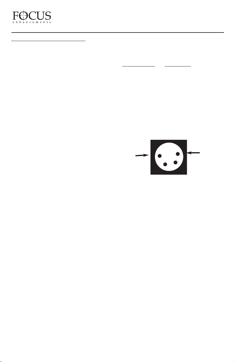
FireStore DR-DV5000 User Guide
TECHNICAL SPECIFICATIONS
Input/Outputs
• DV Video I/O - 25Mb/s
(1 x 6pin IEEE- 1394a)
• External HDD I/O - up to 400Mb/s
(1 x 6pin IEEE-1394a)
• Slot Internal HDD I/O - up to 400Mb/s
(1 x 6pin IEEE-1394a)
• GPI & RS232C Control
(1 x 3.5mm mini jack)
Power
• 2-wire AMP Connection
(from Battery-Camera)
• Anton/Bauer Digital Battery and
IDX Syncron Pass Thru
• 4-pin XLR DC input
• 10V to 17V, 7.5W
Physical Specification
• 2.5lbs (1.1kg) w/ FSHDD-1 Disk Drive
• 4 1/8" x 3 1/2" x 6 1/4"
(105mm x89mm x 159mm)
Audio/Video/Timecode Specification
• 25 Mb/s, 8-bit 4:1:1 (NTSC-DV) or 4:2:0
(PAL-DV) video (model dependent)
• SMPTE or DV embedded timecode
(Drop or Non-Drop for NTSC-DV)
• 2-ch, 16-bit (48kHz) or 4-ch, 12-bit (32kHz)
embedded digital audio
Compliance and Warranty
• CE, C-Tick and FCC
3.5mm to DB9 Serial Cable
DB9 Connector 3.5MM Jack
Pin 2 -> 2 (middle)
Pin 5 -> 3 (barrel or shaft)
Pin 3 -> 1 (tip)
NOTE: It is possible to download the latest
Serial Control Communication Specification
for DR-DV5000 from:
http://www.focusinfo.com/support
Panel Mount 4-pin XLR Power Input
Pin 1
Pin 1 BLACK (-)
Pin 4 RED (+)
Pin 4
Supported DTE Technology File Formats
RawDV (.dv), AVI Type 1 (.avi), AVI Type 2
(.avi), Canopus AVI (.avi), Matrox AVI (.avi),
QuickTime (.mov) or Avid DV-OMF (.omf)
Disk Information
• Internal Disk Type (Slot): FSHDD-1
FireWire Disk Drive
• External Disk Type: User Supplied
IEEE-1394a FireWire
• Disk Format: FAT32
• FAT32 FireWire HDD compatible with
Windows 98SE, ME, 2000, XP and
Mac OS9 and OS10
PAGE 41
Page 43

FireStore DR-DV5000 User Guide
DR-DV5000 RECORD AND CONTROL LCD AND CAMCORDER
VIEWFIDER DISPLAY MODES
When used with a JVC GY-DV5000 series camcorder, it is possible to monitor DR-DV5000 status in the
camcorder’s viewfinder (EVF) and on the LCD display. When DR-DV5000 is connected to a GY-DV5000 and
powered, a small “DD” or “CF” icon will appear in the top right side of the camcorder EVF and LCD. Next to
this will be four characters which will appear like “092S”. The three numerical values (092) represent the
remaining disk space on the FireWire disk drive (in this case 92 minutes). The letter displays the DR-DV5000
Record/Playback and Control Mode (S - in this case STOP). The different display modes are listed below:
PLAY/REC MODE CAM EVF/LCD* DR-DV5000 LCD TALLY
Stop
Pause P blink
Play P > PLAY Off
Rec (Pause) R blink ll REC Blink
Normal Rec (Rec) R REC On
Retro Disk (Stop) S L STOP Off
Retro Disk (Standby) L blink L REC Blink
Retro Cache (Stop) S C STOP Off
Retro Cache (Standby) C blink C REC Blink
Loop Record (Stop) S O STOP Off
Loop Record (Standby) O Blink O REC Blink
Loop Record (Rec) O O REC On
Snap (Stop) S STOP Off
Snap (Standby) G ll SNAP On
Snap (Rec) G ll SNAP On
Time Lapse (Stop) S STOP Off
Time Lapse (Pause) T blink ll T REC Blink
Time Lapse (Rec) T T REC On
S STOP Off
ll PLAY Off
CONTROL TYPE CAM EVF/LCD* DR-DV5000 LCD TALLY
AV/C* (Stop) S A STOP Off
AV/C* (Rec Pause) R Blink
ll A <REC TYPE> REC Blink
AV/C* (Rec) R A <REC TYPE> REC On
V/C* (Play Pause) P Blink
A
YOff
ll A PLA
AV/C* (Play) P A ALL Off
Series Rec** (Stop)
F Blink F STOP Off
Series Rec (Rec) F F REC On
Split Slave** (Pause) R Blink ll <REC TYPE>STOP Blink
Split Slave** (Rec) R R <REC TYPE>REC On
Split Slave** (Stop) S <REC TYPE>STOP Off
Syncro Slave (Pause) Y Blink ll Y <REC
TYPE>REC Blink
Syncro Slave (Rec) Y Y <REC TYPE>REC On
* AV/C is only for use when DR-DV5000 is connected to a computer system. To control DR-DV5000
from a camcorder, use Syncro Slave or Split Slave Mode.
** Series Rec and Split Sla
ve are only available when DR-DV5000 is used with a JVC GY-DV5000
camcorder.
PAGE 42
Page 44

MANL-0908-03
FOCUS Enhancements, Inc.
1370 Dell Ave. Campbell, CA. 95008 USA
Telephone: 408 866-8300 Fax:408 866-4859 www.FOCUSinfo.com
 Loading...