

Page 1
AIR COMMAND
2239
100
80
6
60
4
AIR COMPRESSOR
40
2
ACCESSORY KIT
20
0
psi
lb/in
200
0
kg/cm
3
600
400
0
2
Air
800
120
8
1000
1400
1500
kpa
1200
Bar
140
10
160
12
180
200
14
15
220
Pressure
INSTALLATION INSTRUCTIONS
Congratulations on your purchase of a new Air
Compressor Accessory Kit. This kit will be an asset to your
vehicle, meeting nearly any of your air supply needs.
Please take a few minutes to read through the
instructions, identify the components, and learn how to
properly install your Air Compressor Accessory Kit.
NOTE:
THIS KIT IS NOT DESIGNED TO RUN AIR POWERED TOOLS.
THE COMPRESSOR IS DESIGNED TO RUN AT A 20% DUTY
WITH A MAXIMUM RUN TIME OF 6 MINUTES. PLEASE
CYCLE
ALLOW
BETWEEN
ADEQUATE TIME FOR THE COMPRESSOR TO COOL
RUNNINGS.
NOTE ON CONNECTING AIR LINE TUBING:
Cut the air line tubing as square as possible. To connect
the air line tubing to the fitting, push the tubing into the fitting
as far as possible. If the tubing must be removed from the
fitting, first release the air pressure from the system. Push
the collar on the fitting toward the body of the fitting and
pull out the tubing.
TOOLS REQUIRED:
• UTILITY KNIFE • 3/8" DRILL BIT
• PHILLIPS SCREW DRIVER • 11/16" DRILL BIT
• WIRE CRIMPER/STRIPPER • ELECTRIC DRILL
• (2) 9/16" OPEN-END WRENCH • 1/2" WRENCH
• CENTER PUNCH • 3/8" WRENCH
PARTS LIST
COMPRESSOR 9335 1
AIR TANK 9127 1
PRESSURE SWITCH 9016 1
COMPRESSOR T-FITTING 3066 1
1/4" NPT PTC MALE FITTING 3
BULK HEAD FITTING 1
DRY COUPLER FITTING 1
INFLATION GAUGE UNIT 1
25 FT. EXTENSION HOSE 1
3/8" -16 x 1" HEX BOLT 4
3/8" -16 FLANGED HEX NUT 4
24-8216 08-06 NAD-30734-3
3/8" FLAT WASHER 4
10 -32 x 1" MACHINE SCREW 3
10 -32 NYLON-INSERT HEX NUT 3
3/16" FLAT WASHER 4
18 FT. AIR LINE TUBING 1
NYLON TIE 6
15 FT. 14 GAGE WIRE 1
WIRE CONNECTOR 1
FEMALE SPADE TERMINAL 1
25 AMP BLADE FUSE 1
FUSE HOLDER 1
Page 2
25 AMP FUSE
5
Page 3

BRASS SLEEVE
COMPRESSOR
FOOT
STEP 1 - PREPARE THE VEHICLE
Remove the negative terminal on the battery.
STEP 2 - PREPARE THE COMPRESSOR
RUBBER
ISOLATOR
#10 -32 LOCK
NUT
#10-32 x 1 PAN HEAD
SCREW
#10 FLAT WASHER
BRASS SLEEVE
COMPRESSOR
FOOT
RUBBER
ISOLATOR
VEHICLE
MOUNTING
SURFACE
#10 FLAT WASHER
Figure "B"
moisture. The mounting surface should be rigid to support the compressor, such as under the hood on a fender well
or in a vented storage compartment. The compressor is oil-less and can be mounted in any orientation necessary for
installation.
Using the compressor as a template, center punch, and drill three 3/16" holes. Before drilling, ensure that there are
no electrical , fuel, or brake lines on the opposite side of the mounting surface that can be damaged by the drill. Any
burrs in the holes should be removed to prevent damage to the rubber isolators. Mount the compressor using the supplied
10 -32 x 1" machine screws, 10 -32 lock nuts, and 3/16" washers. See Figure "B". Maximum vibration isolation can
be achieved by properly mounting the compressor. The machine screw and nut should be tightened only enough to
bottom-out the brass insert, see Figure "B". DO NOT OVERTIGHTEN. Overtightening will crush the brass insert
and the rubber isolator, thereby reducing vibration isolation.
Install the rubber isolator feet onto the compressor mounting
brackets. Insert the brass sleeves into the top of the isolator feet, see
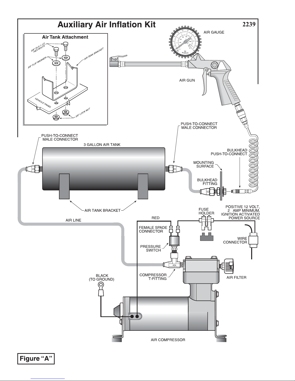
Figure "B". Install the compressor T-fitting into the threaded
exhaust port on the compressor head, see Figure "A". Tighten the
fitting sufficiently to engage the pre-applied orange thread sealant.
(Torque to 40 in. lbs.) DO NOT OVERTIGHTEN THE FITTING.
Install the pressure switch into the compressor T-fitting. Install the air
filter into the threaded inlet port on the compressor head (finger
tight). Install the positive (red) wire from the compressor onto either
spade on the pressure switch, see Figure "A".
STEP 3 - MOUNT THE COMPRESSOR
Select a convenient location to mount the compressor. This location
should provide ample air flow and be protected from airborne debris and
Attach the black wire from the compressor to a grounded component of the vehicle's chassis.
STEP 4 - MOUNT THE AIR TANK
Install the male push-to-connect fittings into both ports on the air tank. Tighten the fitting sufficiently to engage the
pre-applied orange thread sealant. Select a location to mount the air tank. This should be a protected location to prevent
damage from flying rocks or debris. Using the holes in the tank brackets as a template, mark the locations of the mounting
holes on the mounting surface. Use a center punch to mark the center of the holes on the mounting surface. Before drilling,
ensure that there are no electrical , fuel, or brake lines on the opposite side of the mounting surface that can be damaged
by the drill. Drill four 7/16" holes on the center marks. Using the supplied 3/8" hex bolts and flanged hex nuts, attach
the air tank in to the mounting surface. See Figure "A". Ensure clear access to the fittings on the air tank is maintained.
Do not exceed 120 psi in the tank.
STEP 5 - MOUNT BULK HEAD FITTING
Install the bulk head fitting in a convienent protected location. The location could be any rigid flat surface that would
be accessible for easy discharge of air for the end user. Before drilling, ensure that there are no electrical, fuel, or brake
lines on the opposite side of the mounting surface that can be damaged by the drill. Mark and drill a 11/16" hole in the
desired location. Install the bulk head fitting and tighten, see Figure "E". Install the 1/4 NPT fitting on the compressor
side of the bulk head fitting and tighten the fitting sufficiently to engage the pre-applied thread sealant. Install the dry
coupler fitting on the other side of the bulk head fitting and tighten the fitting sufficiently to engage the pre-applied sealant.
Page 4

PLASTIC
CONNECTOR
STEP 6 - ROUTE THE AIR LINE TUBING
Route a length of air line tubing from the push-to-connect fitting on
the air tank to the T-fitting on the compressor. See Figure "A".
Route a length of the airline tubing from the tank to the bulk head
fitting, see Figure "A". Route the air line to avoid sharp edges or heat
from the engine or exhaust system. Using a razor knife, make the cut
as square as possible and push the air line into the fittings as far as
possible. Do not fold or kink the air line tubing.
C
O
N
N
E
C
T
IN
G
W
IR
E
E
X
IS
T
P
IN
O
W
G
E
W
R
IR
E
STEP 7 - WIRE THE SYSTEM
Strip 1/4" off the end of the red 14 gage wire supplied with the kit.
Crimp a female spade connector onto the end of the red wire. Install
Figure "C"
the female spade connector onto the remaining spade on the pressure
switch. Using a wire connector, attach the opposite end of the wire to
an ignition activated, positive 12 Volt, 25 Amp minimum power
source. Consult the manufacturer's wiring diagram for your
vehicle. Slip the wire connector over the existing ignition activated
wire and insert the un-stripped 14 gage wire into the connector. Close
the wire connector over the wires with pliers, see Figure "C".
Install an in-line fuse in the 14 gage power wire, as close to the
power source as conveniently possible. Cut the 14 gage wire and
insert the un-stripped ends into the fuse holder. Close the fuse holder
with pliers and insert a 25 Amp blade fuse. See Figure "D".
FUSE HOLDER
Figure "D"
NOTE: Should additional wire be necessary, 14 gage multistrand
wire may be used.
STEP 8 - TEST THE SYSTEM
Re-attach the negative terminal on the battery. Turn on the vehicle's ignition. The air compressor will run for a short
time to build pressure in the tank. Once the pressure reaches 120 psi in the air tank, the pressure switch will turn the
compressor off. It will not restart until the pressure in the tank drops below 90 psi.
USING THE AIR COMPRESSOR ACCESSORY KIT
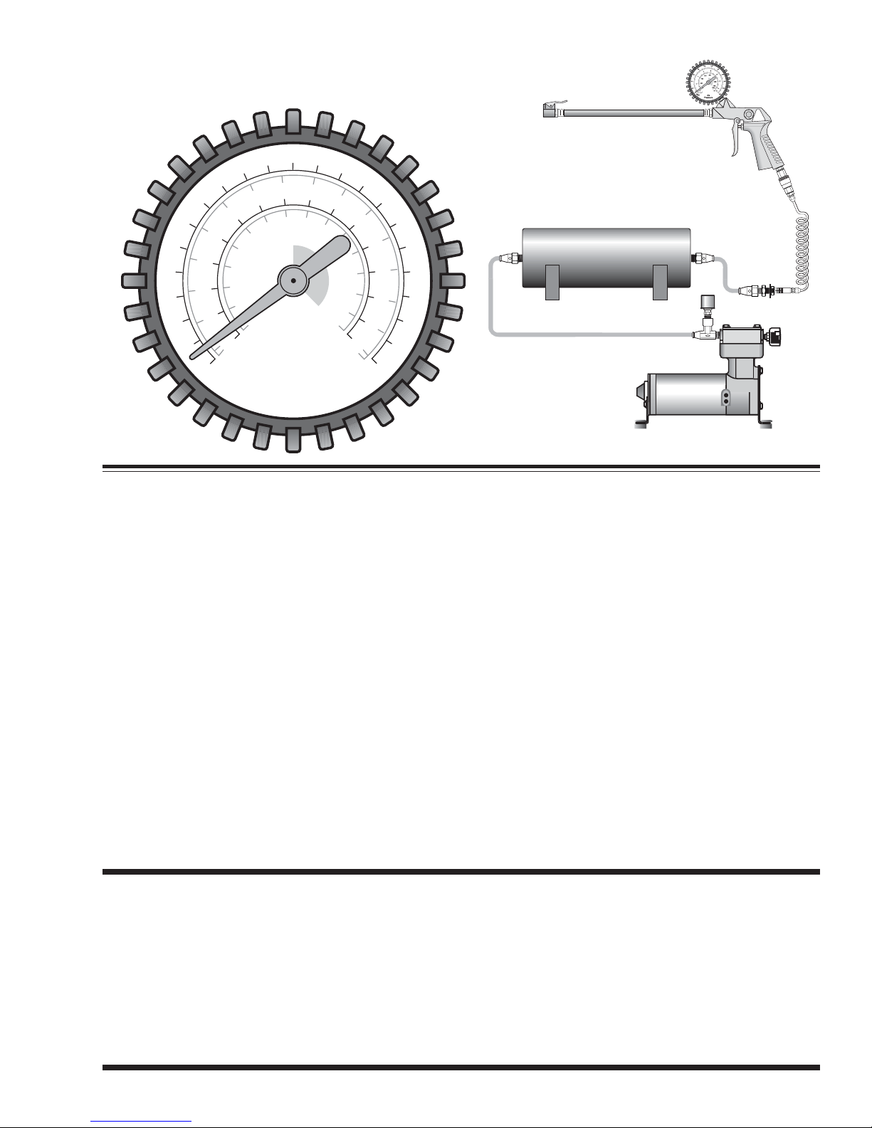
Your system is now ready to use. With the coiled tubing provided, attach the end with the coupler fitting to the bulkhead fitting. Install the coupler fitting on the gauge unit then attach the gauge unit to the coiled tubing You can now use
the air chuck gauge unit for inflation.
FILTER MAINTENANCE
It is recommended that the air compressor filter be inspected periodically. If the filter is sufficiently clogged with
road debris or moisture, it will require replacement.
Figure "E"
 Loading...