

Page 1

Page 2

TABLE OF CONTENTS
WARRANTY . . . . . . . . . . . . . . . . . . . . . . . . . . . . . . . . . . . . . . . . . . . . . . . . . . . . . . . . . .i
LIMITATION OF LIABILITY . . . . . . . . . . . . . . . . . . . . . . . . . . . . . . . . . . . . . . . . . . . . . . . .i
SYSTEM COMPONENTS . . . . . . . . . . . . . . . . . . . . . . . . . . . . . . . . . . . . . . . . . . . . . . . . .2
HEIGHT SENSOR INSTALLATION . . . . . . . . . . . . . . . . . . . . . . . . . . . . . . . . . . . . . . . . . . .5
PROGRAMMING THE SYSTEM . . . . . . . . . . . . . . . . . . . . . . . . . . . . . . . . . . . . . . . . . . . . .8
OPERATION OF THE SYSTEM . . . . . . . . . . . . . . . . . . . . . . . . . . . . . . . . . . . . . . . . . . . . .9
MAINTENANCE . . . . . . . . . . . . . . . . . . . . . . . . . . . . . . . . . . . . . . . . . . . . . . . . . . . . . . .9
COMMONLY ASKED QUESTIONS . . . . . . . . . . . . . . . . . . . . . . . . . . . . . . . . . . . . . . . . . .10
TROUBLE SHOOTING . . . . . . . . . . . . . . . . . . . . . . . . . . . . . . . . . . . . . . . . . . . . . . . . . .12
WARRANTY
What is covered
Firestone Industrial Products Company warrants the IntelliRide system to be free of defects in material and workmanship for a period of one year or 12,000 miles (whichever occurs first) from the date of original purchase.
If the control system or any part of the control system fails because of a manufacturing defect, Firestone will, at
its option, provide replacement part(s) for the consumer, without charge, provided
the customer:
1) Returns the component/system to the original purchase location, an authorized Firestone distributor.
2) Submits proof of original purchase.
What is not covered
1) Installation or service charges for replacement parts.
2) Damage caused by incorrect installation.
3) Parts that have been altered or tampered with.
4) Damage caused by vehicle accident.
5) Damage from misuse or abuse.
6) Damage caused by extraordinary environmental conditions or events, such as fire, flood or
acts of God.
LIMITATION OF LIABILITY
Warrantor is not responsible for consequential damages. Some states do not allow the exclusion or limitation
of incidental or consequential damages, so the above limitation or exclusion may not apply to you. The warranty
gives you specific legal rights, and you may also have other rights, which vary from state to state. To know
what your legal rights are in your state, consult your local or state consumer affairs office or your state’s
Attorney General.
Vehicle Note: Prior to installation of this kit, the air springs must be installed to your vehicle. Air pressure and
air lines should be removed from the air springs prior to the installation of the Intelliride™ system.
i
24-8201 09-04 NAD-32047-2
Page 3

C
C
ongratulations on your purchase of a new IntelliRide system by Firestone. This kit will provide automatic height control and leveling of
your vehicle. The following will introduce you to the system components as well as provide detailed instructions concerning installing the
height sensors and programming the system. Be sure to take all applicable safety precautions during the installation of this kit. Position
the vehicle on a solid level surface and apply the parking brake. Disconnect the negative battery cable from the battery. With the vehicle on a solid,
level surface raise the vehicle and remove the wheels. After the removal of the wheels, lower the vehicle so the suspension rests on jack stands
rated for your vehicle's weight.
TOOLS REQUIRED
> Drill > 1/2” End wrench > Phillips head screw driver
> 3/8” Drill bit > 10mm End wrench > Sharp knife
> 3/16” Drill bit > 8mm End wrench > Pliers
> Center punch > 7mm End wrench > Tape measure
> Hacksaw > 3/8” End wrench > Marker
> 1” Hole saw > 9/16” End wrench
PARTS LIST
ii
Top Box Components Part # Qty
Valve block 9235 1
Pressure Sensor 0002 1
1/4 NPT Straight Fittings 3100 8
Air Compressor 9210 1
Electronic Control Unit 0200 1
Air Dryer 0004 1
Height Sensors 0100 4
Height Sensor Bracket 5342 4
Height Control Rod 3265 4
Height Sensor Template 8252 4
Bottom Layer Components Part # Qty
Air Tank, 3 Gallon 9127 1
Wire Harness & Connections Part # Qty
Variable Leveling Connection (Park Wire) 0008 1
Wire Harness With Switches, Grommet 9238 1
Hardware & Tubing Part # Qty
Separate Plastic Bag with:
Hardware Required for Height Sensor Installation (Figure 2)
10-32 x 1” Machine Screw 8
10-32 Nylon Lock Nut 8
3/16” Flat Washer 8
M5 x 8 mm Machine Screw 8
M6 x 16 mm Machine Screw 4
M6 Nylon Lock Nut 4
Height Control Arm 4
Hardware Required for Height Sensor Linkage Installation (Refer to
Figure 6)
Hose Clamp 4
Axle Mounting Bracket 4
Height Control Linkage 8
M5 Nylon Lock Nuts 8
M5 Jam Nut 8
1/4” Tubing, 18ft. 1
Hardware & Tubing Part # Qty
Separate Plastic Bag with:
Hardware Required for Component Mounting & Air Fittings
Valve Block Mounting Hardware & Exhaust Silencer
Silencer 3271 1
10-32 x 1-3/4” Socket Head Cap Screw 2
10-32 Nylon Lock Nut 2
3/16” Flat Washer 2
Compressor Isolator Mounting Hardware & Air Fitting
1/8 NPT Fitting 1
10-32 x 1” Machine Screw 3
10-32 Nylon Lock Nut 3
3/16” Flat Washer 6
Ground Wire Mounting Hardware
1
0-32 x 1” Machine Screw 1
10-32 Nylon Lock Nut 1
3/16” Flat Washer 1
ECU Mounting Hardware
10-32 x 1” Machine Screw 1
10-32 Nylon Lock Nut 1
3/16” Flat Washer 1
Air Dryer Mounting Hardware and Air Fittings
3/8 NPT Straight Fitting 2
10-32 x 1” Machine Screw 4
10-32 Nylon Lock Nut 4
3/16” Flat Washer 4
Compressor Relay Mounting Hardware
10-32 x 1” Machine Screw 1
10-32 Nylon Lock Nut 1
3/16” Flat Washer 1
Reservoir Mounting Hardware & Air Fittings
3/8” – 16 Flange Lock Nut 4
3/8” Flat Washer 4
3/8” – 16 x 1” Hex Head Bolt 4
1/4” NPT Plug 1
1/4” NPT Fitting 1
Tie Wraps to Securely Mount Wire Harness 30
Thermal Sleeves to Protect Tubing 4
Inflation Valve for Height Sensor Installation 4
(Air Spring Method)
Torque Recommendations - 1/4 NPT Tank Plug: Tighten the fitting securely to engage the orange thread sealant.
NPT Fittings: Tighten the air fitting so as to make contact with the nylon ring and then tighten 1/4 turn to snug the fitting. No thread sealant is needed.
Pressure Sensor: The pressure sensor is sensitive to over-torque. Carefully install the pressure sensor into the valve block with 7.2 ft-lbs. (9.8 N-m) of torque.
Page 4

Battery Connection
Connections to be made with
vehicle interior
Program button. This is discon-
nected after programming and
replaced with the Park Wire.
Connector to ECU, to be mounted
inside the vehicle.
Service Switch to be used
to turn the system on and
off.
Ignition wire and ground wire.
Ignition wire should be connected
to a source less than 1/2 amp.
Grommet to be used if needed
in the firewall.
Height Control
Switch
Compressor Relay
To be mounted inside engine bay.
Figure 1
Page 5
1
IntelliRide
™
Full System Schematic
DET DESCRIPTION
1 FULL SYSTEM VALVE ASSEMBLY
2 AIR COMPRESSOR
3 AIR TANK - 3 GALLON
4 ELECTRIC CONTROL UNIT (ECU)
5 HEIGHT SENSORS
6 1/4 TUBING 18ft.
7 WIRE HARNESS FULL SYSTEM
8 AIR DRYER - SYSTEMS
9 BRACKET - HEIGHT SENSOR
10 3/8 NPT FITTING, 1/4 TUBE
11 1/8 NPT FITTING, 1/4 TUBE
12 1/4 NPT FITTING, 1/4 TUBE
13 1/4 NPT PLUG
14 1/4 NPT SILENCER
15 PRESSURE SENSOR
3/16” Flat Washer (16)
10-32 Nylon Lock Nut (13)
10-32 x 1” Machine Screw (11)
Miscellaneous Mounting Hardware
Page 6

SYSTEM COMPONENTS
Wire Harness
All necessary electrical wires and connectors have been included with this kit. Review Figure 1 before beginning
installation. You will have to put the major components in a position so that the wire harness will reach all of them.
Route the wire harness loosely throughout the vehicle as indicated in Figure 1. Each end of the wire harness is
marked with the major component that it will connect with.
Route the wire harness loosely throughout the vehicle as indicated in Figure 1, with the spine of the wire harness
installed on the right side of the vehicle.
Compressor Relay
Select a location in the engine compartment to mount the compressor relay. This should be a protected location
to prevent damage from flying rocks, water or debris. The compressor relay is located on the wire harness,
simply pull the compressor relay off the wire harness for mounting. Ensure that a clear access to the electrical
connection on the compressor relay is maintained. Then plug the wire harness marked “relay” back into the
compressor relay connector.
Electronic Control Unit (ECU)
The main electronic unit needs to be mounted in the interior of the vehicle, preferably under the dashboard. The wire
harness was designed to provide enough length so the ECU could be mounted under the dashboard and the harness
ran through the firewall to corresponding corners, valve block and power connections.
Valve Block
The valve block should be placed in a protected location to prevent damage from flying rocks or debris. Ensure that a
clear access to all of the fittings on the valve block is maintained. The valve block should be mounted with solenoids
pointing up or sideways, never pointing down. In order to ease installation, abbreviations for the correct plumbing
connections are scribed into the valve block.
The valve block abbreviated connector notations are:
OD = outflow from dryer LF = left/front air spring PS = pressure sensor EX = exhaust
RF = right/front air spring ID = inflow to dryer LR = left/rear air spring Comp Inlet = compressor inlet
RR = right/rear air spring
2
10-32 x 1-3/4” Socket Head
Cap Screw (2)
Silencer
(1)
Pressure
Sensor (1)
1/4” NPT Straight
Fittings (8)
TIPS
1. Do not run the wire harness near vehicle exhaust system.
2. Secure harness firmly to vehicle with
the provided tie wraps.
3. Make sure wire harness does not interfere with any moving parts of the vehicle.
4. Start with the ECU connectors and
then begin running the harness into the
interior of the vehicle.
5. Many vehicles have a blank hole in the
firewall to run wires through.
6. A grommet has been provided if a 1”
hole must be cut to get the wire harness
to the interior. Before drilling the holes,
make sure all electrical, brake and fuel
lines are cleared from the path of the drill.
Page 7

SYSTEM COMPONENTS (cont.)
Height Sensors
The height sensor connections must go to their corresponding corners for proper sensor operation. THE HEIGHT
SENSORS AND THE WIRE HARNESS CONNECTIONS ARE LOCATION AND POSITION SENSITIVE. The sensor
connectors are laid out so they work with the sensors mounted on the outside of the frame rail, with the arms pointed
toward the rear of the vehicle. If the height sensors are mounted inside of the frame rail, the arms must point toward
the front of the vehicle. The system WILL NOT work if the height sensors are mounted incorrectly or if the wire
harness connector is in the wrong corner.
Compressor
Select a convenient location for mounting the compressor. This location should provide ample air flow and be
protected from most airborne debris. The surface should be rigid to support the unit. Some examples might include
under the hood on a fender well, or in a vented storage compartment.
Using the compressor feet as a template, mark the three 3/16” holes. Remove the compressor and drill the three
3/16” holes. Before drilling the holes make sure all electrical, brake and fuel lines are cleared from the path of the
drill. It is recommended that burrs be removed from the holes so as not to damage the rubber isolator. Mount the
compressor using the 10-32 machine screws, 10-32 nylon lock nuts and 3/16” flat washers located in your hardware
pack. Proper mounting of this compressor will provide maximum isolation. DO NOT OVER TIGHTEN, further
tightening will crush the insert and isolator and reduce vibration isolation. Secure the ring terminal to a grounded
component of the vehicle’s chassis. Find the red wire on your wire harness marked air compressor. Connect the
wiring harness to the female spade terminal on the compressor.
3-Gallon Air Tank
Select a location to mount the air tank. This should be a protected location to prevent damage from flying rocks or
debris. Using the holes in the tank brackets as a template, mark the locations of the mounting holes on the mounting
surface. Use a center punch to mark the center of the holes on the mounting surface.
Before drilling the holes make
sure all electrical, brake and fuel lines are cleared from the path of the drill
. Drill four 3/8” holes on the center
marks. Using the supplied 3/8”-16 x 1” hex bolts and 3/8”-16 nuts and 3/8” washers, attach the air tank to the vehicle. Ensure that a clear access to the fittings on the air tank is maintained.
3
Shown with mounts
and air filter.
1/8 NPT Fitting (1)
3/8”-16 x 1 Hex
Head Bolt (4)
3/8”-16 Flat
Washer (4)
3/8”-16 Flange
Lock Nut (4)
1/4 NPT
Fitting (1)
1/4 NPT
Plug (1)
Air Tank Mounting Hardware
M5 Nylon Lock
Nut (8)
M5 x 8mm
Machine Screw (8)
M6 Nylon Lock
Nut (4)
M6 X 16mm
Machine Screw (4)
Axle Mounting Bracket (4)
Hose Clamp (4)
Height Control Linkage (8)
Height Control Arm (4)
Height Sensor Template (4)
Height Sensor Bracket (4) Height Sensor (4)
Page 8

SYSTEM COMPONENTS (cont.)
Air Dryer
Select a location to mount the air dryer. This should be a protected location to prevent damage from flying rocks or
debris and close to the valve block. Ensure that a clear access to all of the fittings on the air dryer is maintained.
Height Selection Switch
The height selection switch may be mounted directly in the dashboard, only if the dashboard material is 1/8” in thickness or less. The height selection switch is located on the wire harness, simply pull the switch off the connector by
depressing the locking clip and pulling the connector off of the switch. To mount the switch to your vehicle, snap the
height selection switch into the open hole with the arrows on the back of the switch pointing up. Then take the wire
harness marked height selection switch and plug the end back into the back of the height selection switch until you
hear it click.
Service and Program Switches
The service switch is basically the ON/OFF switch for the system. It will not operate when RED is showing. When the
switch shows all BLACK the system is functional and will return the vehicle to the height prior to ignition off. The
service switch should be used to disable the system if repairs to the vehicle need to be made. I.E. changing tires,
damper work (such as shock absorber replacements), working under the vehicle or general repairs. The service
switch may be mounted in an area that you can easily access if you need to work on the vehicle’s suspension. The
service switch will mount in panel material that is 1/8” in thickness or less.
The program switch is located on the wire harness. Simply pull the switch off the connector to mount it to your vehicle. After mounting the switch to the vehicle, reconnect the switch to the wire harness. The switch should click into
the harness connector when connecting.
Variable Leveling Response Connection (Park Wire)
As an extra feature, an additional connection wire has been provided that will allow the vehicle to level itself within 5
seconds compared to the standard response time of 40 seconds. This quicker response is desirable when the vehicle
is parked and the payload is increased, providing the user with a more immediate confirmation of leveling. The tan
variable-leveling-response wire with clear connector will be attached to the wire harness in the same location
originally used for the red program switch. Install the park wire after the system has been successfully programmed.
To connect the wire:
1. Unplug the program button. 2. Plug in the park wire connector. 3. Connect the other end of
the park wire to ground or to a switch that will be grounded when the vehicle is NOT in park. This can be done via a
customer supplied switch that will switch out ground for the faster leveling while the vehicle is not moving or the tan
wire can be connected to a vehicle wire/switch that will not be grounded while the vehicle is in park (i.e. parking
brake signal).
Park wire if not grounded = Fast, overly active response
Park wire if grounded = Slow, normal response
Note: If the park wire is not connected, the compressor will be more active than necessary. Install the park wire after the
system has been successfully programmed.
The faster leveling feature is not desirable for normal driving conditions because the system will become too active,
(i.e. - leveling when not desired during cornering).
4
Service
Switch
Program
Switch
Page 9

5
HEIGHT SENSOR INSTALLATION
Step 1
There will be a bag in your kit with all of the hardware that you will
need to put the height sensors on your vehicle. Group a height
sensor from the kit with a height sensor bracket and two M5 x
8mm machine screws as indicated in Figure 2. Attach the bracket
and height sensor template to the sensor using the machine
screws, as shown in Figure 2. Next group a sensor arm and one
M6 x 16mm and one M6 lock nut. Attach the metal arm to the
sensor arm with the M6 x 16mm and the M6 lock nut, refer to
Figure 2. Repeat this procedure for the three other sensors.
Step 2
In the process of installing the height sensors the vehicle suspension must be able to go though the entire suspension movement,
with damper attached, from full jounce to full rebound to mechanically prove height sensor position, refer to Figure 3. This can be
done by either using jack method or the air spring method.
Jack Method
Raise the vehicle using a lift or platform jack rated for your vehicle
weight. Do not use wood or concrete blocks to support the weight
of the vehicle. Lower the vehicle frame onto jack stands rated for
your vehicle’s weight making sure the suspension is fully extended
to damper limit. Then to determine the jounce suspension position
that you will need to mount the height sensors, just jack the suspension up to that point into the jounce stop. Make sure that the
air line is removed and that there is no air in the air springs when
using this method.
Air Spring Method
Cut four sections of air line tubing 3” in length and insert into
each air spring. Install the four inflation valves
(included with sys-
tem)
in the end of each hose. Now you can inflate and deflate the
air springs on suspension to find the location to mount the height
sensors. This will also make calibration easier.
Step 3
Avoid direct heat from the engine and exhaust pipe when installing
height sensors. The height sensor linkage to the suspension
should be as close to 90° from sensor arm at ride height as possible. The sensor arm and sensor linkage should not be inline
throughout the entire travel of the height sensor linkage, from full
jounce to full rebound. An incorrectly mounted height sensor will
result in system not functioning. The height sensor must be
mounted with the electrical connection pointing up and the arm
in the correct position on the sensor.
Note: The best description of a poorly mounted height sensor is shown in Figure 3. Too big of an angle between the height
sensor arm and link may allow the arm to “toggle” over center.
Figure 2
Page 10

6
HEIGHT SENSOR INSTALLATION (cont.)
Step 4
To install the height control sensor, refer to Figure 4a, 4b and 5, to
become familiar with the mounting geometry and hardware. Be
sure that the area above and below the sensor location on the axle
is clear of obstructions for the arm to move.
Step 5
Take the sensor under the vehicle and find a location where the
sensor may be attached to the vehicle so that the arm extends
over the suspension. The arm of the sensor must be able to travel
from full jounce to full rebound for the system to work properly.
Looking at the table below pick out a hole on the sensor arm that
will work on your suspension attachment point. The use of the
provided template will show minimum and maximum arm movement as shown in Figure 3. At ride height the height sensor arm
should be as horizontal as possible.
Hole location Approx. Working range
(from sensor out) (of sensor)
First hole on the sensor arm 2”
itself (6mm)
Second hole 3”
Third hole 4”
Fourth hole 5”
Fifth hole 6”
Notice that the maximum working range of the sensor is 6”, even
with the linkage placed in the fifth hole of the sensor arm. If your
suspension provides more than 6” of travel, you will have to position the sensor so that operates within the yellow portion of the
sensor installation template. For example, if you have a 4-link type
rear suspension, you can simply locate the linkage a bit closer to the pivot of the 4-link arm on one of the 4-link bars. By attaching the linkage a bit
closer to the pivot of the 4-link arm, the sensor “sees” less suspension movement than if it were attached directly at the axle location. The object is
to make sure that the suspension movement does not move the sensor arm out of its range of authority as outlined in Figure 3. On an independent
front suspension, simply place the linkage somewhere inboard of the ball joint to effectively lessen the travel of the sensor. If the sensor arm
exceeds it range of authority, the IntelliRide™ system will not respond. See page 12 & 13 for diagnostic information.
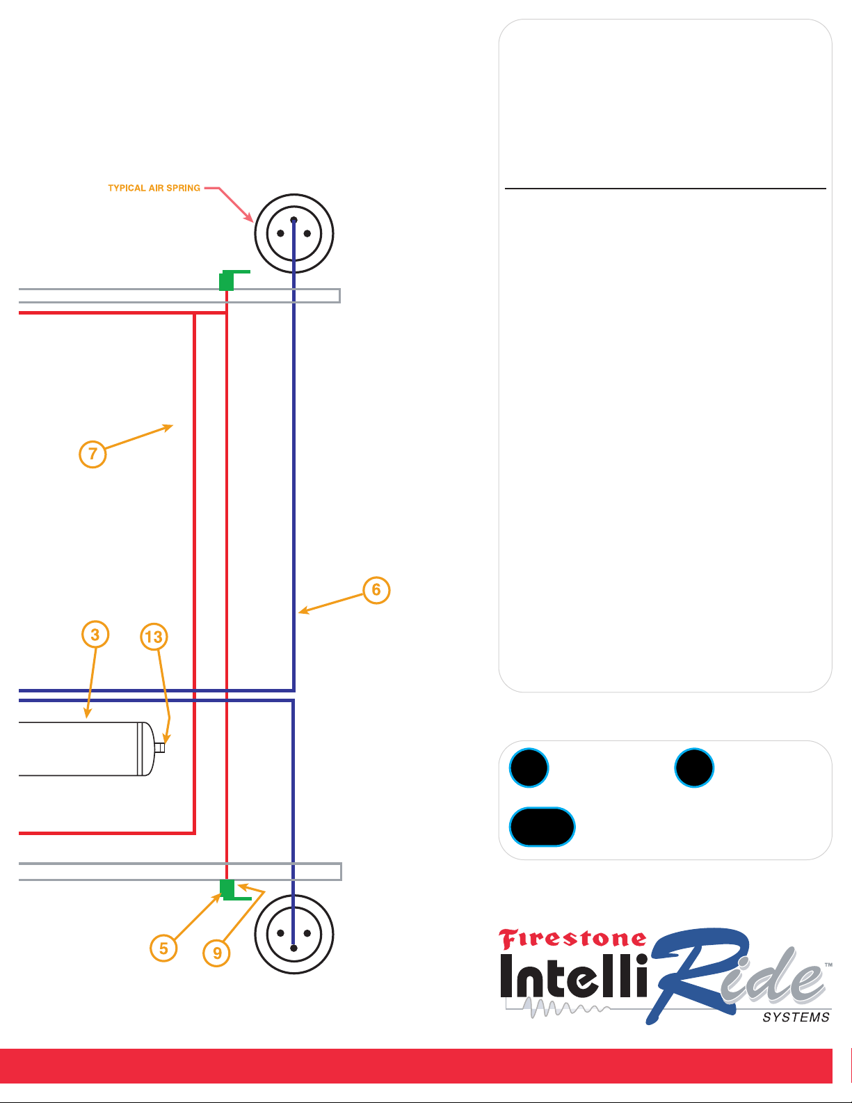
What direction do the height sensors need to be mounted with the
WR8-760-2230 IntelliRide system?
If provided with a wire harness the power and ground to each vehicle corner
expects the height sensor arm to be in a certain position relative to the body of
the sensor. If mounted backwards the system would act in reverse, or not at
all. The height sensors on the right side of the vehicle need to be mounted with
the arm in the 9:00 position. The height sensors on the left side of the vehicle
need to be mounted with the arm in the 3:00 position.
Page 11

HEIGHT SENSOR INSTALLATION (cont.)
Step 6
Once the sensor positions have been found, mark the locations of
the mounting holes on the vehicle frame using the holes in the
height sensor bracket as a template, refer to Figure 3 and Figure
5. Use a center punch to mark the center of the holes on the
mounting surface. Before drilling the holes make sure all electrical, brake and fuel lines are cleared from the path of the drill. Drill
two 3/16” holes on the center marks. Mount the height sensor
bracket using the 10-32 X 1” machine screws, 10-32 nylon lock
nuts and 3/16” flat washers located in your hardware pack. Ensure
that a clear access to the electrical contact on the top of the height
sensor is maintained.
Step 7
Place the axle bracket on the suspension below the height sensor
arm. This bracket does not have to be on top of the suspension.
This bracket can be mounted to the suspension with provided 1032 x 1” machine screw and 10-32 Nylon lock nut or by clamping
the bracket to the suspension with the provided hose clamp.
Step 8
To install the linkage from the suspension to the height sensor
arm. Put suspension at either full rebound or full jounce; mark off
link from suspension position ball joint and to corresponding sensor link ball joint according to template as per Figure 3. That position is now set. Slowly move suspension to the opposite end of its
travel ensuring that the sensor arm stays within the limits of the
template. The parts that you will need for the linkage are M5
threaded rod, two M5 jam nuts, two M5 linkages and two M5
Nylon lock nuts. Layout the linkage with the same distance measured as shown in Figure 3. If the threaded rod is too long it can be
cut to length using a hacksaw. Install the M5 jam nut over both
ends of the threaded rod, cut if needed, and then install the linkages on both ends as shown in Figure 6. Install the finished linkage on the axle bracket and the height sensor arm using the two
M5 Nylon lock nuts. The linkages can be screwed up or down on
the shaft for fine adjustment to insure that you are not out of sensor range as explained in Height Sensor Installation: Step 5.
Adjustment of linkage can be used to adjust sensor arm to achieve
centered arm travel as depicted in Figure 3. The height sensor
template can be removed if desired.
7
Figure 6
How much travel should I have?
The amount of travel is dependent upon the working range of the
height sensor arm and linkages. The system will perform if the sensor arm operates within the yellow section of the sensor template.
The height sensor arm needs to be in the specified working range
(yellow area of the template) throughout the entire suspension
travel, not only through the travel for the selected lowered and
raised heights. Allowing travel outside of this working range will
result in a system fault.
Page 12

8
PROGRAMMING THE SYSTEM
For the system to operate properly the vehicle suspension travel will need to be programmed into the ECU.
Reconnect the negative terminal on the battery.
Step 1: Programming Setup
Plug the program switch into the wire harness that is labeled program switch. Turn the system off using the service switch. When the system is off
the side of the switch will be red. Turn on the vehicle’s ignition and leave it on until the entire programming of the vehicle’s heights is done. There
should be no lights on the height selection switch at this time. Push the program switch three times within six seconds. The lower light on the
height selection switch should start blinking. This will be indicating that jounce height (lowest) needs to be programmed into the ECU.
Step 2: Programming the Lowest Vehicle Height
Set the lowest height of your vehicle’s suspension by either using inflation valves at each corner or jack stands. Note: Lowest height cannot be fully
deflated. When all four corners of the vehicle are at the jounce height that you determine, hold the program switch in for eight seconds. Both lights
on the height selection switch should start blinking indicating that the ride height needs to be programmed into the ECU.
The full jounce position should be a minimum of 1/4” from where the jounce bumper stops. This small gap is required to allow for a tolerance as
the suspension height is controlled by the ECU. Without this small tolerance, the ECU will not achieve the lowered height if the suspension is
stopped before the ECU believes the lowest vehicle height is reached.
STEP 3: Programming the Vehicle Design Height
Set the ride height of your vehicle’s suspension by either using inflation valves at each corner or jack stands. When the vehicle is at the ride height
that you determine, hold the program switch for eight seconds. The top light on the height selection switch should start blinking. This will indicate
that the highest height needs to be programmed into the ECU.
STEP 4: Programming Highest Height
Set the highest height of your vehicle’s suspension by either using inflation valves at each corner or jack stands. The rebound position should be a
minimum of 1/2” from where the rebound stops.
This small gap is also required to allow for a tolerance as the suspension height is controlled by the ECU. Without this small tolerance, the ECU
may not achieve the highest height if the suspension is stopped before the ECU believes the highest vehicle height is reached. When the vehicle is
at the rebound height that you determine, hold the program switch in for eight seconds. Both lights on the height selection switch should start
blinking back and forth. This will indicate that the calibration height needs to be programmed into the ECU.
STEP 5: Programming Calibration Height
This calibration step teaches the relative suspension reaction to the IntelliRide system. Specifically this sets the internal tolerance bands and provides a relationship between the voltage that the ECU reads and the suspension height. Lower the height of each corner one inch by either using
inflation valves at each corner or jack stands. When the vehicle is at the calibration height, hold the program switch for eight seconds, and then
release. Both lights in the height selection switch should be on at the completion of programming. Turn off the vehicle’s ignition, and switch the
service switch so that it is all black and not showing red. After the proper airlines are installed and the vehicle’s ignition is turned back on, the system will put the vehicle at standard ride height and pressurized the air tank.
Note: Highest height cannot be fully extended, as this will generate a rough ride and may damage the dampers.
Note: When you choose your jounce height, ensure there is a small gap between travel stops and suspension.
Lowered HeightStandard HeightRaised Height
Page 13

OPERATION OF THE SYSTEM
Once height programming has been completed, the system is ready for use. The height selection switch
is how you will be able to select your height. The switch has two green lenses with arrows printed on
them. This is the primary user interface of the air leveling system. If the switch is mounted correctly,
pressing up will make the height go up and pressing down will make the height go down. When a
height selection is made up or down, the lights will toggle fast during the height change. Corresponding
lights will tell you which height you are at. *If the lights toggle slow or both of them blink slow, a fault
has occurred, see the Trouble Shooting section for a more detailed description.
The system has four modes of operation:
Lowered Height - Indicated by a illuminated lower switch lens
Ride Height (or standard height) - Indicated by no illuminated switch lenses
Raised Height - Indicated by a illuminated upper switch lens
Currently achieving Height - Indicated by both illuminated switch lenses flashing alternately.
Lowered Height is designed to be used for show, or ease of ingress and egress from the vehicle. The
vehicle should not be driven in this mode.
Ride Height is designed to be the primary operating position of the vehicle. This mode allows maximum
up and down travel of the suspension. A full air suspension can be set flat and level. This mode offers
the best ride and handling.
Raised Height is designed to allow maximum ground clearance. This mode offers slightly reduced ride
and handling.
Currently Achieving Height is designed to indicate when the system is actively trying to achieve your
last mode change request. This will typically occur when vehicle has first been started and on
driver selection.
Notes:
> Caution should be taken when vehicle is changing heights that the vehicle does not come in
contact with any object or person during the height change.
> Never have any part of your body under vehicle during height change.
> Never lift a running vehicle by the frame without first disabling the system.
MAINTENANCE
Periodically check all parts for defects. Also check all filters to make sure they are clean and debris free.
It is wise to check reservoir for water, which indicates the air dryer may need to be changed as the
system may have a leak.
9
Page 14

COMMONLY ASKED QUESTIONS
What is the lifetime expectancy of the Firestone dryer?
If there are no system leaks it should be for good for system life.
What type of accuracy is available with our system?
The height sensors that we use are capable of an accuracy of 0.67% of 1 degree. Our system with ECU programming is designed to work with 1/4
of a degree of accuracy. For comparison sake, a pneumatic leveling valve can have a dead band of approximately 3/8”.
How do electronics help increase the life of the compressor?
Mechanical valves waste air when the vehicle goes around corners or stops with a wheel in a hole or on a curb. The ECU recognizes these situations and responds accordingly, not allowing unnecessary air consumption. The situations when mechanical valves cause unnecessary compressor
use can be approximately 15% of trip time.
Are the valves environmentally protected?
The valves are plated for corrosion protection.
Are the connectors environmentally protected?
Firestone uses connectors that have IP68 moisture protection. This means they can withstand 1/2-meter water depth.
Why do the height sensors need to be mounted with the arms in a certain direction?
If provided with a wire harness the power and ground to each vehicle corner expects the height sensor arm to be in a certain position relative to
the body of the sensor. If mounting backwards, the system would act in reverse, or may not work at all.
Does the ECU have to be reprogrammed if the power source is removed?
No, the memory is nonvolatile.
How durable is the Firestone height sensor arm?
The height sensor arm of the Firestone system is designed to withstand the most severe vehicular environments. The sensor has been used on
high-mileage and off-road applications. The tensile load that the arm has withstood approximately 600lbs in an application. Although the arm is
designed for durability, this durability is a function of proper installation. Offset, shear loading has the potential to damage the arm. While it is true
that the shear loading can be corrected using a strong, metal arm the force will then be exerted elsewhere in the sensor. The result is typically
cracking the sensor body or pivot point leading to the introduction of moisture, corrosion and failure.
Is the ECU certified for electromagnetic interference (EMI)?
The Firestone ECU has been certified to E11 standards, far exceeding the base requirements for EMI. This means that the Firestone IntelliRide system does not emit an electromagnetic disturbance that will affect other electronic systems.
What is electromagnetic interference (EMI)?
Any electromagnetic disturbance that interrupts, obstructs, or otherwise degrades or limits the effective performance of electronics/electrical equipment. It can be induced intentionally, as in some forms of electronic warfare, or unintentionally, as a result of spurious emissions and responses,
intermodulation products, and the like.
How much travel should I have with my WR8-760-2230 IntelliRide system?
The amount of travel is dependent upon the working range of the height sensor as well as the position of the height sensor arm and linkages
(mechanical advantage). The system will perform if the sensor arm operates within the yellow section of the sensor template. Refer to Step 5 of
Height Sensor Installation in the 2230 Installation Instructions.
Is the ECU environmentally protected?
The ECU has a conformal coating agent which protects it from moisture.
10
Page 15

COMMONLY ASKED QUESTIONS (cont.)
In the WR8-760-2230 system, which port from valve block goes to & from the dryer?
Each port on the valve block is labeled for the designated connector. Using the air line tubing, measure the distance from each port of the dryer
back to the valve block. The air line tubing should be routed from the I.D. (inflow to dryer) port on the valve block to the in port on the dryer. The
next air line tubing should be routed from O.D. (outflow from dryer) port on the valve block to output side of the dryer. Cut the air line tubing
accordingly, as squarely as possible. Push the air line tubing into the fittings as far as possible.
What do all of the abbreviations on the valve block refer to in the WR8-760-2230 IntelliRide System?
O.D. = outflow from dryer R.F. = right/front air spring L.F. = left/front air spring I.D. = inflow to dryer P.S. = pressure sensor L.R. = left/rear air
spring R.R. = right/rear air spring EX. = exhaust COMP. INLET = compressor inlet
What do I do with the park wire if I have a manual transmission in the WR8-760-2230 IntelliRide system?
The park wire needs to be connected to a ground or to a customer supplied switch that will be grounded when the vehicle is NOT in park. One
potential input is the parking brake.
In step 3 of Height Sensor Installation of the WR8-760-2230 Installation Instructions it mentions that the sensor arm and linkage
should not be inline. What does that mean?
The best description is shown in the upper right-hand corner on page 6 of the 2230 Installation Instructions, Figure 3. Too big of an angle between
the height sensor arm and link will pull the sensor and may allow the arm to toggle over center.
Why should I use the thermal sleeves provided within the WR8-760-2230 IntelliRide system?
Thermal sleeves have been provided for to protect tubing from direct heat from the engine and exhaust pipe. If a thermal sleeve is required simply
slide the sleeve over the air line tubing to the location requiring protection.
How does the system indicate that the programming portion of the installation is complete in the WR8-760-2230
IntelliRide system?
In step 5 of programming the vehicles heights there is an indication that the process is completed. Please proceed with the instructions as specified in the included 2230 Installation Instructions. When the vehicle is at the calibration height, hold the program switch for eight seconds, and
then release. Both lights on the height selection switch should be on at the completion of programming. FYI: The lights will not turn on immediately at the completion of programming. Please allow a maximum of 30 seconds.
Are the height sensors environmentally protected?
The height sensors are IP68 rated, meaning they can withstand a water depth of 1/2-meter. These height sensors have survived severe off road
driving conditions in water, snow and mud.
Where should the ignition wire on the WR8-760-2230 aftermarket IntelliRide system be connected?
The purple ignition wire should be connected to a source with less than 1/2 amps. Typically a standard ignition wire under the dash of the vehicle
is suitable. A source with more than 1/2 amps can potentially damage the ECU.
What type of dryer is used with our system?
The dryer is regenerative. This means that the dryer is maintenance free assuming that there is not a leak in the system. A leak would not allow the
system to exhaust enough air through the dryer to adequately dry the air.
How much current does the IntelliRide electronic air spring system pull?
When the system is off the ECU draws less than a battery powered watch. When the system is on the max draw is dependant on how many valves
are in operation, i.e. when no valve activity then we draw less than 1 amp but for each valve up to 1.5/2.0 amps, three valves being the most open
at one time. The height indicator lights are LED’s and draw very little current.
Why does the compressor relay need to be mounted inside the engine compartment?
The relays are not sealed units. This is why it is recommended that they are installed inside the engine compartment.
11
Page 16

TROUBLESHOOTING
The height change works, but the WR8-760-2230 system will not level. The left-rear corner is exhausted fully. The LED height
display shows the current height.
The right-front valve is switched with the left-rear valve. Correct the air line connection with the corresponding air spring location and the solenoid
valve connection.
The height change works, but the WR8-760-2230 system will not level. The right-rear corner is exhausted fully. The LED light display shows the current height.
The left-front valve is switched with the right-rear valve. Correct air line connection with air spring location and solenoid valve block.
On the WR8-760-2230 IntelliRide system the height change works but leveling is confused. The system is very active and unable
to achieve level. The LED switch displays the current height.
The left-front valve is switched with right-rear valve, or left-rear valve is switched with right-rear valve. Another possibility is the left-front height
sensor is switched with the right-front height sensor, or left-rear height sensor is switched with right-rear height sensor. Correct air line connection
with air spring location and solenoid valve block; or position height sensor locations according to the wire harness labels.
On the WR8-760-2230 IntelliRide system the height change and leveling is confused. System will detect if a height change is
made but can take up to 2 minutes. The LED lights toggle slow.
There are a couple possible causes and related solutions. (1) A possible cause is the left-front valve is switched with left-rear valve. Correct air line
connection with air spring location and solenoid valve block. (2) Another possible cause is the front height sensors are switched with the rear
height sensors. Correct the location of the height sensors to the corresponding corners as indicated on the wire harness.
On the WR8-760-2230 IntelliRide system the height change up will not work; will not level up. The current height is displayed on
the LED lights.
The possible cause is the inlet valve is removed. Check for pinched airlines and check wire connections to valve block.
On the WR8-760-2230 IntelliRide system the height change down will not work; will not level down. The current height is displayed on the LED lights.
The possible cause is the exhaust valve is removed. Check for pinched airlines and check wire connections to valve block.
On the WR8-760-2230 IntelliRide system the height change will not work properly; system will attempt to height change and will
go back to previous height. Will not be able to level corner. The LED lights show that the current height is displayed.
The possible cause is any corner valve is removed. Check for pinched air lines and check wire connections to valve block.
The WR8-760-2230 IntelliRide system cannot make a height change; the compressor will not run. The LED lights toggle slowly.
There are a few possible causes: (1) The possible cause is the compressor fuse is blown. (2) Compressor power not connected. (3) Ground on
relay connector not connected. (4) Compressor not grounded. Solution: Check the compressor ground, compressor fuse and relay connections.
The WR8-760-2230 IntelliRide system will not level or height change to the set height. The LED lights show the current height.
Calibration height set too far from the highest vehicle height. Redo calibration height so that it is approximately 1-inch below the highest vehicle
height.
The WR8-760-2230 IntelliRide system is very active at one height. The LED lights show that the current height is displayed.
A possible cause is that the park wire is not connected, meaning the system is looking to level the vehicle every 5 seconds instead of every 40 seconds. Please install the park wire as described in the installation manual.
12
Page 17

TROUBLESHOOTING (cont.)
The diagnostic lights on the WR8-760-2230 aftermarket IntelliRide system toggle fast as though it is attempting to change
heights, and the valve block clicks trying to pass air. However no height change occurs and there is no air pressure within the
reservoir tank.
(1) There is a potential blockage in the air dryer.
(2) The compressor connections are not sufficient.
(3) The pressure sensor is not connected.
The WR8-760-2230 system is locked down, with no functions. Both of the lights on the LED switch flash slowly.
There are a few different causes and solutions:
(1) The pressure sensor is unplugged. Insure that the pressure sensor is torqued into the valve block at the recommended torque
value of 7.2 ft-lbs (9.8 N-m). Make sure pressure sensor is plugged in firmly.
(2) The height sensor(s) is/are unplugged. Insure that each height sensors is securely connected into the wire harness.
(3) The height sensor(s) is/are out of range.
Insure that the height sensor arm travels within the recommended yellow area of the height sensor template. It is also important that the height
sensor are mounted correctly with the wire connection pointing up. (4) The pressure sensor is out of range. Insure the pressure sensor connector
is fully inserted and wires into the connector are not exposed (5) +5Volts removed. Ensure sensor power wire is inserted on the ECU connector.
The WR8-760-2230 is locked down, no function. The system will not level or change height. The lights toggle slowly.
The ground is removed from the valve block. Check grounding on valve block wire.
The WR8-760-2230 system is locked down, no function without any indication from control switch.
There are few potential causes and related solutions. (1) System is off due to the main ground removed. Check all fuses, power, ignition and
ground connections (2) The system is off due to the voltage battery is removed. Check all fuses, power, ignition and ground connections. (3) The
ignition connection is removed. Check all fuses, power, ignition and ground connections. (4) The service switch is showing red. Turn the service
switch so that it is showing all black. (5) Make sure the ignition wire is connected to a source of less than 1/2 amps.
The WR8-760-2230 system will not function. The leveling and ability to change height is disabled. Both lights flash slowly.
The pressure sensor low limit failure caused by grounding out. Insure the pressure sensor connector is fully inserted and wires into the connector
are not exposed.
The vehicle will attempt to raise the vehicle, but after an extended period of time the attempt is unsuccessful and the vehicle
returns to its previous height.
The 2230 IntelliRide system is designed to time-out if a height is not achievable. Common reasons for an unachievable height change include:
1) the air springs are too large and have air volume requirements that exceed the capabilities for this specific air system or, 2) the air springs do
not have enough load capacity to lift the vehicle.
13
Page 18

For the latest technical information and support
questions/answers, please visit: www.fsip.com/ir
14
Page 19

TECHNICAL
15
Page 20

Firestone Industrial Products Company
12650 Hamilton Crossing Blvd.
Carmel, IN 46032-5400
www.fsip.com/Intelliride
 Loading...