

Page 1
Firestar™ vi30/40 Dual Cooled Laser Quick Start Guide
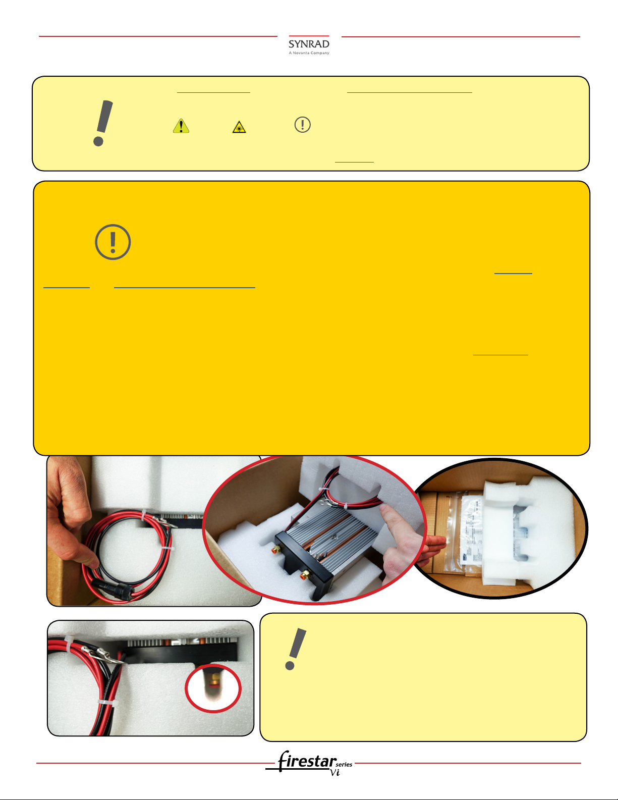
Carefully push the wire harness through the notch in the top foam piece, and save with packaging.
Laser Unpacking:
Important
Note:
Caution
Possible
Equipment
Damage
Mounting feet and/or rails are optional, for complete details, refer to the laser’s Operator’s Manual and
drawings and Mounting Quick Start Guide located on our website.
If you discover shipping damage, document the damage (photographically if possible), then immediately
notify the shipping carrier (responsible party) and SYNRAD. After unpacking, review the Inventory list in the
Intro section within the operators manual.
If you need a replacement box for packing and/or shipping your laser, contact us.
Caution! When re-packing the laser for relocation or shipment, use compressed shop air (less than 29
1. Unseat the wiring by sliding the harness out of
PSI) to blow out excess water from the cooling systems. Wear safety goggles! Nothing can be on the
the notch, then down and out of the foam as
sides of the laser at any time as damage will occur. There is only one way the laser ts into the foam! All
shown below.
components must be stowed under the laser. Re-package the wire harness as shown above. The wire
harness &/or ports can be damaged in shipping if not re-packaged as shown in this guide, the drawings,
operation manual, and/or resources located in our website.
See your Marking Head (If utilized) and the laser’s Operators Manual for complete installation details and instructions.
Read all Danger, Warning, Caution terms, symbols, and instructions located in
the (Laser Safety Hazard information) sections in the Laser’s Operation Manual and in
our Laser Safety/Compliance 101 on our website.
Caution! Unpacking the wire harness incorrectly can lead to damage.
Keep All specially designed Foam Packaging and end-caps, you will need to re-use it
when re-packaging/moving your laser. Refer to this guide and the Technical Reference
chapters in the laser’s Operation Manual when re-packaging for shipping and/or relocation. Hint-if laser doesn’t re-seat into the foam easily, try ipping it around 180 degrees.
2. Remove the laser from the box and locate the
mounting hardware kit at the bottom of the
box under the laser.
Hint:
If laser does not reseat easily, try ipping it around
1 vi30/40 Dual Cooled QSG Version 2.1
Important Re-packaging Note:
Assure the two (2) H2O ports are nested inside
the foam notches, & all residual water drained
from the system.
There is only one way the laser ts into the foam!
so the ports sit into the foam as shown.
Page 2
Firestar™ vi30/40 Dual Cooled Laser Quick Start Guide
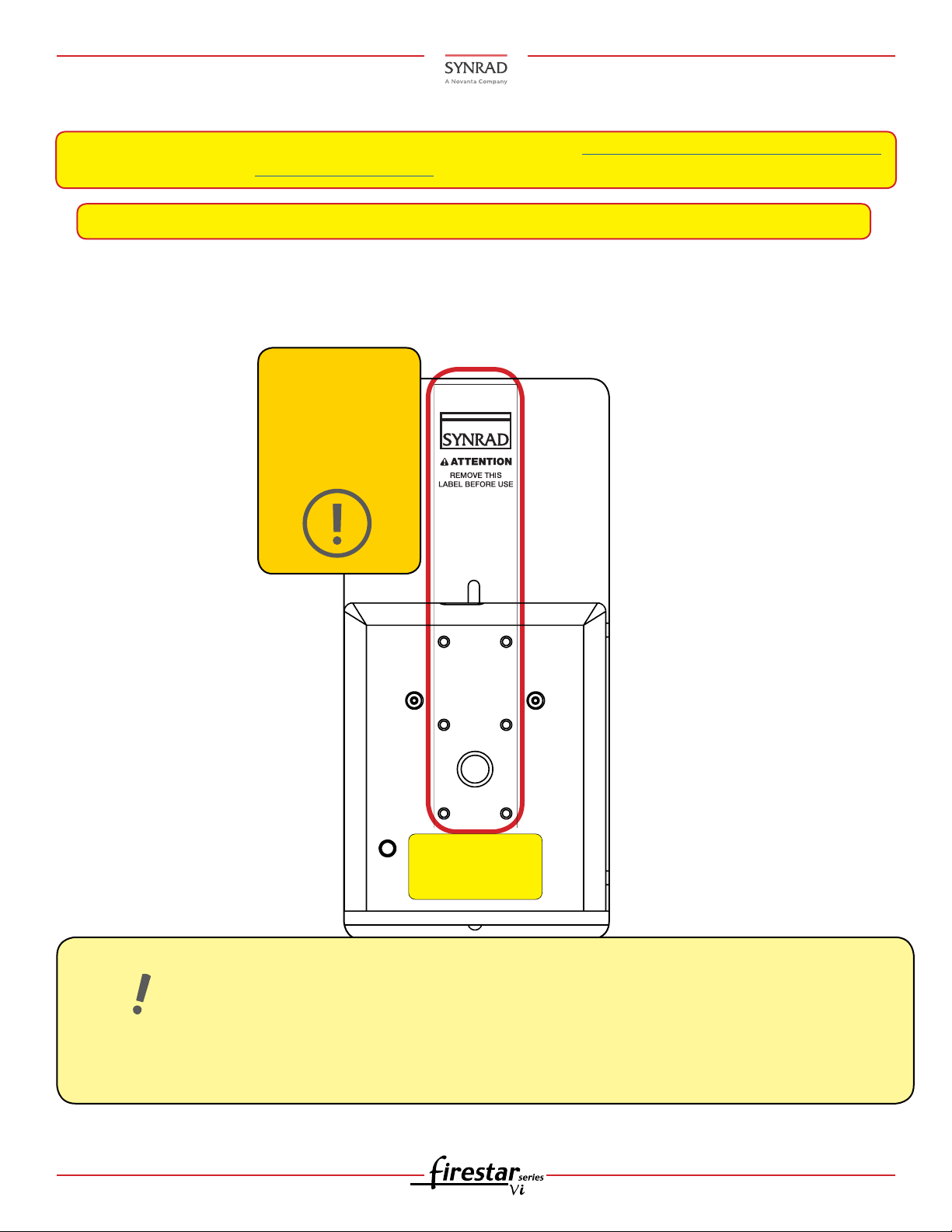
AVOID EXPOSURE
Invisible laser radiation
is emitted from
this aperture.
OPTICAL
ACCESSORY
MOUNTING (x6)
Laser Unpacking (Continued):
Note: IF using the FH Flyer marking head with your laser, go to the Mounting & FH Flyer Quick Start Guide
and reference the FH Flyer & WMPv6 QSG located on our website.
Note: IF not using a SYNRAD marking head OR mounting kit with your laser, see the section below.
Readying your Laser for use:
3. Failure to remove the aperture seal can damage your system!
Failure to
remove can
damage the
laser!
Important
Note:
SYNRAD does not recommend mounting lasers in a vertical, (head and/or tail down)
position. Please contact the factory for limitations as a vertical orientation increases the risk
of damage to the lasers optics.
Consult the factory for further mounting angle guidance outside >75% from the horizontal. When mounting the laser to a baseplate, use only one metric or SAE fastener per mounting tab on the baseplate. Do not
use any type of jackscrew arrangement as this will twist the baseplate and may distort the tube.
2 vi30/40 Dual Cooled QSG Version 2.1
Page 3
Firestar™ vi30/40 Dual Cooled Laser Quick Start Guide
Front
Back
Mounting:
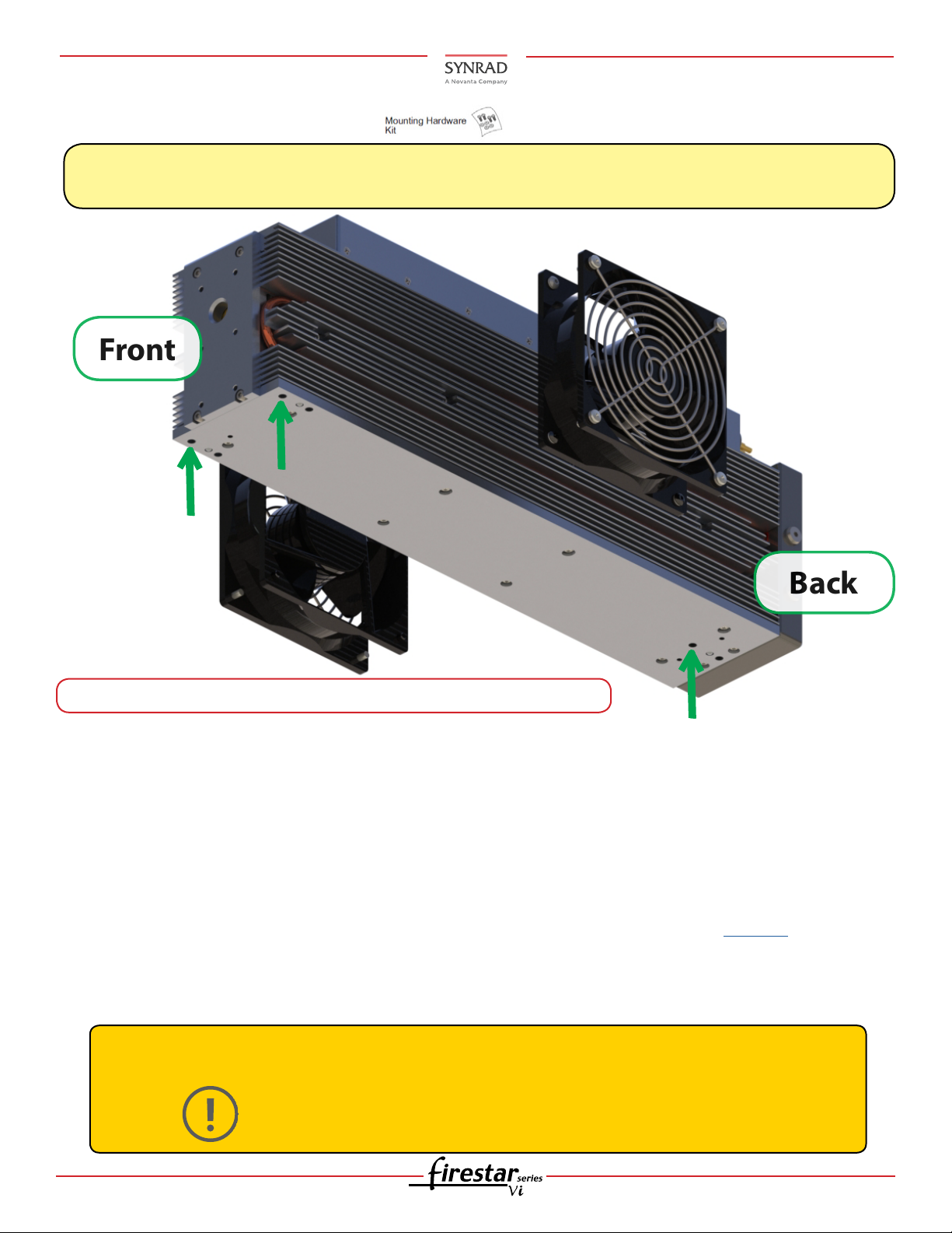
4. Locate the Mounting Hardware ( ).
Note:
Three ball bearing “feet” pressed into Firestar’s base plate eliminate any possible distortion of the
laser tube caused by variations in the flatness of the mounting surface.
4.1 Standard Mounting Dual cooled with fans shown (vi30 shown).
5. Choose your mounting type.
A. Standard Mounting (smallest footprint):
B. Tall Mounting (matches v30 height-for upgrading from v30 to vi30/40 for mounting from below):
The ‘Tall’ mounting kit (SYNRAD® P/N 250-20190-01).
C. Tall/Wide Mounting (matches v30 height-for upgrading from v30 to vi30/40 for mounting from
above): The ‘Tall/Wide’ mounting kit (SYNRAD P/N 250-20190-02).
6. Standard Mounting: Drill three thru holes in the nal mounting surface that correspond to either the
ISO (metric) or UNC fastener pattern shown in the O&M drawings located on our website.
7. Insert the three M6 × 1 ISO or 1/4–20 UNC fasteners through the mounting surface into the
corresponding threaded holes Evenly tighten all capscrews to a maximum torque of 6.1 Nm (54 in lb).
Caution
Possible Equipment
Damage
When mounting from below, mounting bolts must not extend further
than 6.0 mm (0.24 in) into the base plate. Otherwise damage to the laser
may occur.
3 vi30/40 Dual Cooled QSG Version 2.1
Page 4
Firestar™ vi30/40 Dual Cooled Laser Quick Start Guide
(Matches v30 Beam Exit & Mounting)
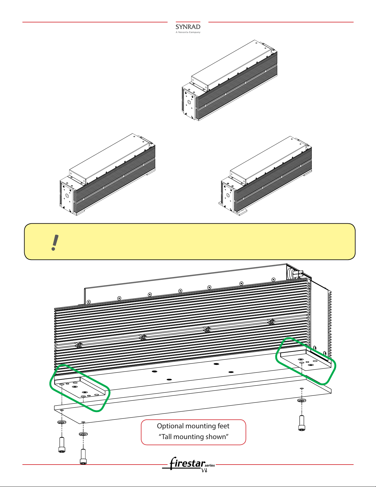
Optional mounting feet
“Tall mounting shown”
Mounting (Continued):
Standard vi30 Baseplate
(Smallest Footprint)
Important
Note:
‘Tall’ Mounting Feet
(Matches v30 Beam Exit Height)
‘Tall/Wide’ Mounting Feet
When mounting the Firestar laser, use only one metric or SAE fastener per mounting tab on
the baseplate. Do not use any type of jackscrew arrangement as this will twist the baseplate
and may distort the tube.
4 vi30/40 Dual Cooled QSG Version 2.1
Page 5
Firestar™ vi30/40 Dual Cooled Laser Quick Start Guide
>2.25 in (57.2 mm)
‘Minimum’ clearance
< 3.0 in (76 mm)
< 3.0 in (76 mm)
Front
Top View
Measure chassis temperature
at this location
Cooling:
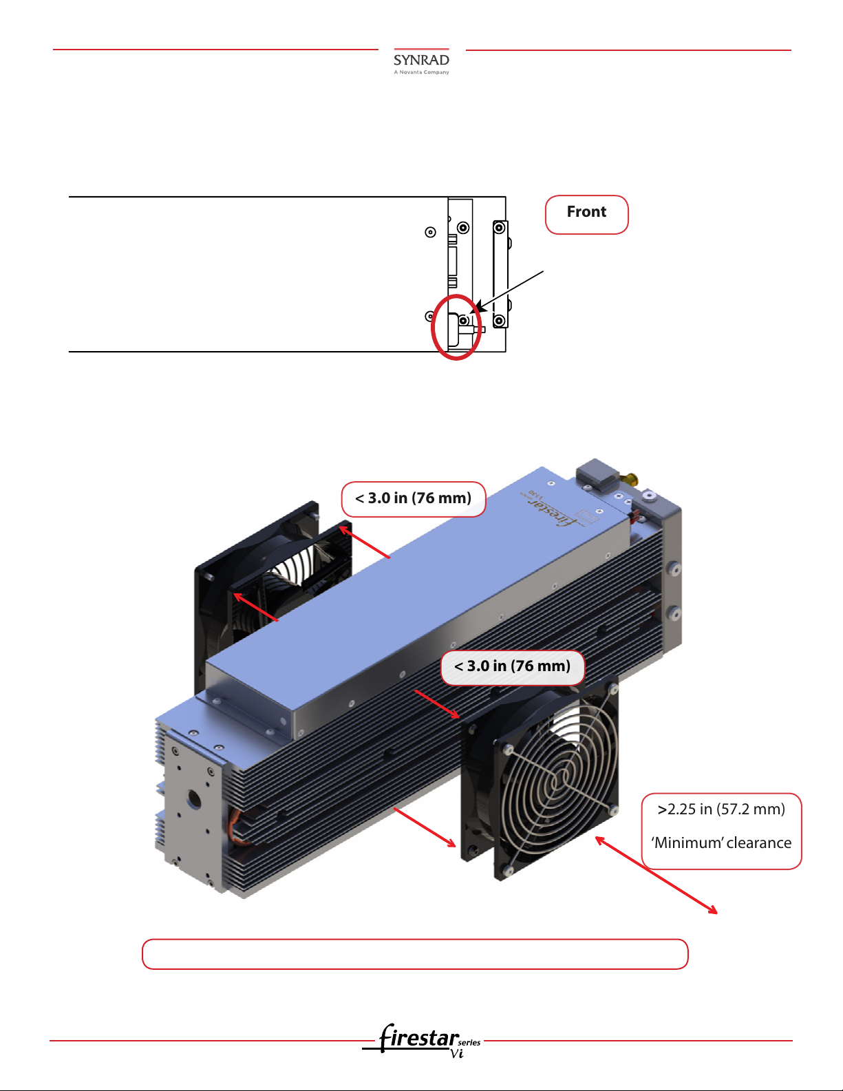
8. If temperature monitoring is desired, see the following gure for customer supplied external tempera-
ture sensor.
9. Installing the fans: Assure the gap between fan and laser must be less than 3.0 in (76 mm). Minimum
fan-to-wall clearance is 2.25 in (57.2 mm) otherwise damage will occur!
9.1 Dual-cooled units can be cooled with either fans or water. (vi30 shown).
5 vi30/40 Dual Cooled QSG Version 2.1
Page 6
Firestar™ vi30/40 Dual Cooled Laser Quick Start Guide
Cooling (Continued):
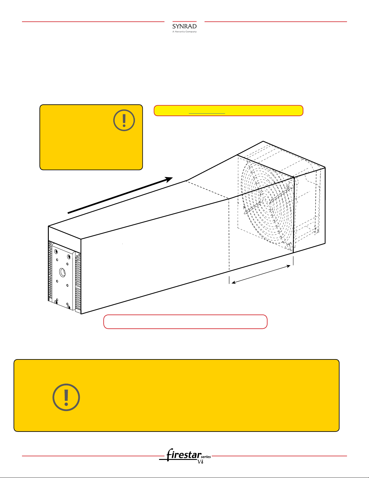
10. If rear cooling is desired: Design the cooling shroud so that it encloses the full length of the laser and
cooling fan. Assure the shroud ts snugly against the heatsink ns so that cooling air is conducted
through them and not around them. For adequate heat removal, open the shroud at the front to direct
air ow through the laser. Use a cooling fan rated at least 8.5 m3/min (300 cfm) at a static pressure of
23.9 mm H2O (0.94 in H2O) and position it approximately 150 mm (6.0 in) from the rear of the laser. See
the cooling specications in the Technical Reference section of the laser’s Operation Manual.
Caution
Possible Equipment
Damage
Customer designed fan
shroud must enclose both
the OEM laser and cooling
fan!
Airflow Direction - Front to Rear
Note: See Cooling 101 located on our website.
Allow 6 inches
clearance
Things to know:
Caution
Possible
Equipment
Damage
6 vi30/40 Dual Cooled QSG Version 2.1
Recommended fan shroud design for rear cooling.
If you operate your laser or marking head in a dirty or dusty environment, contact
SYNRAD about the risks of doing so and precautions you can take to increase the
longevity of your laser, marking head, and associated optical components.
A risk of exposure to toxic elements may result when certain optical or beam
delivery components are damaged. In the event of damage to laser, marking head,
or beam delivery optics, contact SYNRAD, or the optics manufacturer for handling
instructions.
Page 7
Firestar™ vi30/40 Dual Cooled Laser Quick Start Guide
Water In
from chiller
Water Out
to chiller
Cooling (Continued):
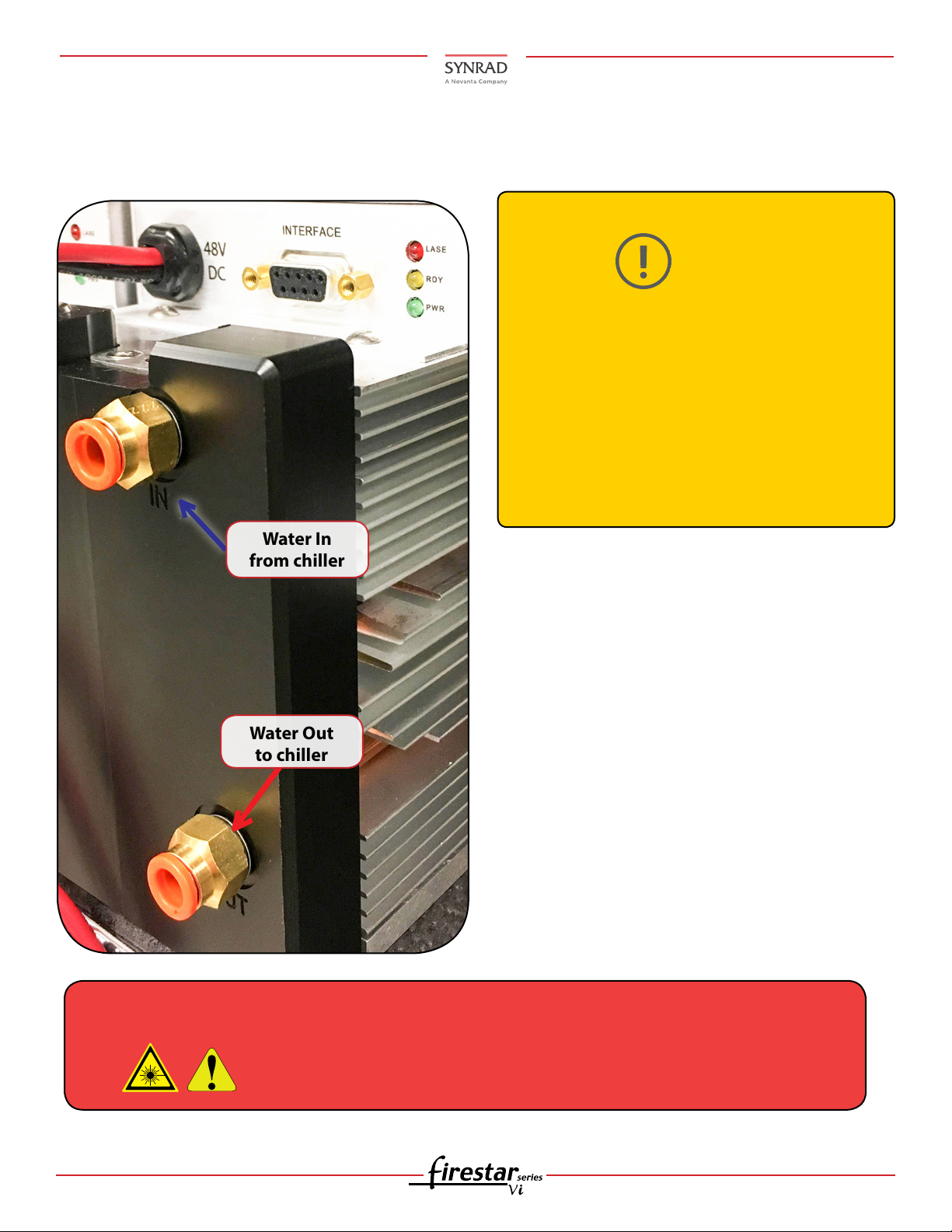
11. Water cooling: Assure the water in from the chiller and out to the chiller are aligned appropriately
with the ‘In’ and ‘Out’ markings on the back of the laser.
Caution
Possible
Equipment
Damage
If you operate your laser or marking head in a
dirty or dusty environment, contact SYNRAD
about the risks of doing so and precautions
you can take to increase the longevity of your
laser, marking head, and associated optical
components.
The stability of the unit will be aected if the
water in/out is reversed!
Do not exceed coolant
pressure of 414 kPa
(60 PSI)!
Things to know:
Our lasers incorporate the following wetted materials in the coolant path—nickel-plated brass, copper,
Acetal®, nitrile, Viton®, PBT, Delrin®, Polyethelene,
and stainless steel.
Warning!
Serious Personal
Injury
Avoid glycol-based additives because they reduce
the coolant’s heat capacity and high concentrations
may aect power stability. If you must use glycol,
do not add more than 10% by volume. See the
Operation and/or Technical Reference sections in
this Manual for detailed information. Glycol is not
necessary unless the chiller is subjected to freezing
temperatures.
A risk of exposure to toxic elements may result when certain optical or
beam delivery components are damaged. In the event of damage to
laser, marking head, or beam delivery optics, contact SYNRAD, or the
optics manufacturer for handling instructions.
7 vi30/40 Dual Cooled QSG Version 2.1
Page 8
Firestar™ vi30/40 Dual Cooled Laser Quick Start Guide
Cooling Guidelines:
Caution
Possible
Equipment
Damage
Daily inspections for signs of water damage due to condensation is highly recommended!
Overnighting cooling fittings may crack the cooling manifold, assure the max insertion depth is no more
than 6.6 mm (0.26) in into the cooling manifold. Maintain coolant pH above 7. Operating the laser with a
coolant temperature below the dew point of the surrounding air may cause condensation to occur that
will damage the laser! The setpoint temperature MUST be maintained above the dew point temperature.
If tap water is utilized, chloride levels must be below 25 Parts Per Million (PPM). Water total hardness must
be below 100 PPM. If hardness is an issue, install a filter on the chiller’s return line and inspect regularly.
First push and hold the tubing slightly into the tting. Next push the white tting ring evenly to-
wards the tting, and then pull the tubing free.
After disconnecting tubing from a tting, trim 12.7 mm (0.5 in) from its end before reconnecting.
Trimming the end of the tubing before reconnecting provides an undisturbed sealing surface.
Use distilled water as the coolant. If glycol is necessary, (temperatures below freezing) add no more than 10% by volume. Use a corrosion inhibitor/algaecide such
as Optishield©. When filling your chiller, use at least 90% distilled or tap water by
volume. Biocides may contain chlorides that shall not exceed 25 PPM. See the technical reference chapter in the laser’s Operation Manual for the dew point table and
cooling specifications.
If tubing needs to be disconnected from a tting:
Push tubing completely into the tting. Test the tting by giving the newly installed tubing a slight
tug to verify that it is locked into place. Tubing extends into the tting approximately 22 mm
(0.875 in).
Note:
Quick disconnect or compression type ttings can be utilized. These tubing adapters are available from many tubing and tting manufacturers. Do not use 1/2 inch size tubing of ttings
without appropriate adapters, doing so increases risk of coolant leaks.
Guidelines for cutting and installing tubing
Cut tubing lengths generously to allow for trimming.
Cut tubing squarely; diagonal cuts may not seal properly. Trim away any burrs if the cut is “ragged”.
Avoid excessive stress on ttings by creating a gentle radius when bends in the tubing are close to
ttings. Bending tubing too sharply will compromise the sealing properties of the tting.
Never allow the tubing to kink, since kinking severely restricts coolant ow.
Push tubing completely into the tting, then pull the tubing to verify that it is locked into place.
p100/150 cooling ttings are designed to accept 12 mm polyethylene tubing.
If adaption is required, we recommend McMaster-Carr (P/N 51495K416).
8 vi30/40 Dual Cooled QSG Version 2.1
Page 9
Firestar™ vi30/40 Dual Cooled Laser Quick Start Guide
Cooling Guidelines (Continued):
When coolant temperature is lower than the dew point, the temperature at which moisture condenses out of the surrounding air, condensation forms inside the laser housing leading to failure of laser
electronics as well as damage to optical surfaces. Do not operate your laser in these conditions.
The greatest risk of condensation damage occurs when water-cooled lasers are run in a high heat/high
humidity environment and the chiller’s coolant temperature is colder than the dew point temperature of
the surrounding air or when the system is shut down, but coolant continues to ow through the laser for
extended periods of time. See the dew point table in the laser’s Technical Reference chapter located in the
Operation Manual.
The chiller’s temperature setpoint must always be set above the dew point temperature. In cases where
this is not possible within the specied coolant temperature range of 18 °C to 22 °C (64 °F to 72 °F), then the
following steps MUST be taken to reduce the risk of condensation damage.
A. Stop coolant ow when the laser is shut down.
B. Air-condition the room or the enclosure containing the laser.
C. Install a dehumidier to reduce the humidity of the enclosure containing the laser.
D. Install gas purge- Introduce nitrogen or dry ltered air into the laser housing*.
*See Assist gas purity and Purge gas specications in the Technical References section of your lasers Operation Manual. See the Facilities/Utilities (Air Drop or Gas Purge Port) in the next few sections of this guide.
Caution
Possible
Equipment
Damage
Choosing the correct coolant temperature and ttings are important to the proper operation and longevity
of your laser otherwise internal condensation and/or water damage will occur that could void your warranty!
Reference the dew point chart for temperatures and range of air temperature and relative humidity values
in the technical references chapter of the lasers Operation Manual.
Remember that the laser’s coolant temperature must be set above dew point temperatures.
Do not ow coolant through the laser for an extended period of time when the laser
is shutdown. This causes condensation to form inside the laser which may result in
catastrophic damage to internal optics and electronic circuits.
Inlet cooling water temperature must always be maintained above the dew point to
prevent condensation and water damage to your laser.
Note: For further details, please see the Laser and Marking Head Operation Manuals.
Also reference your Marking Head Quick Start guide (If using) located on our website to com plete initial setup.
9 vi30/40 Dual Cooled QSG Version 2.1
Page 10
Firestar™ vi30/40 Dual Cooled Laser Quick Start Guide
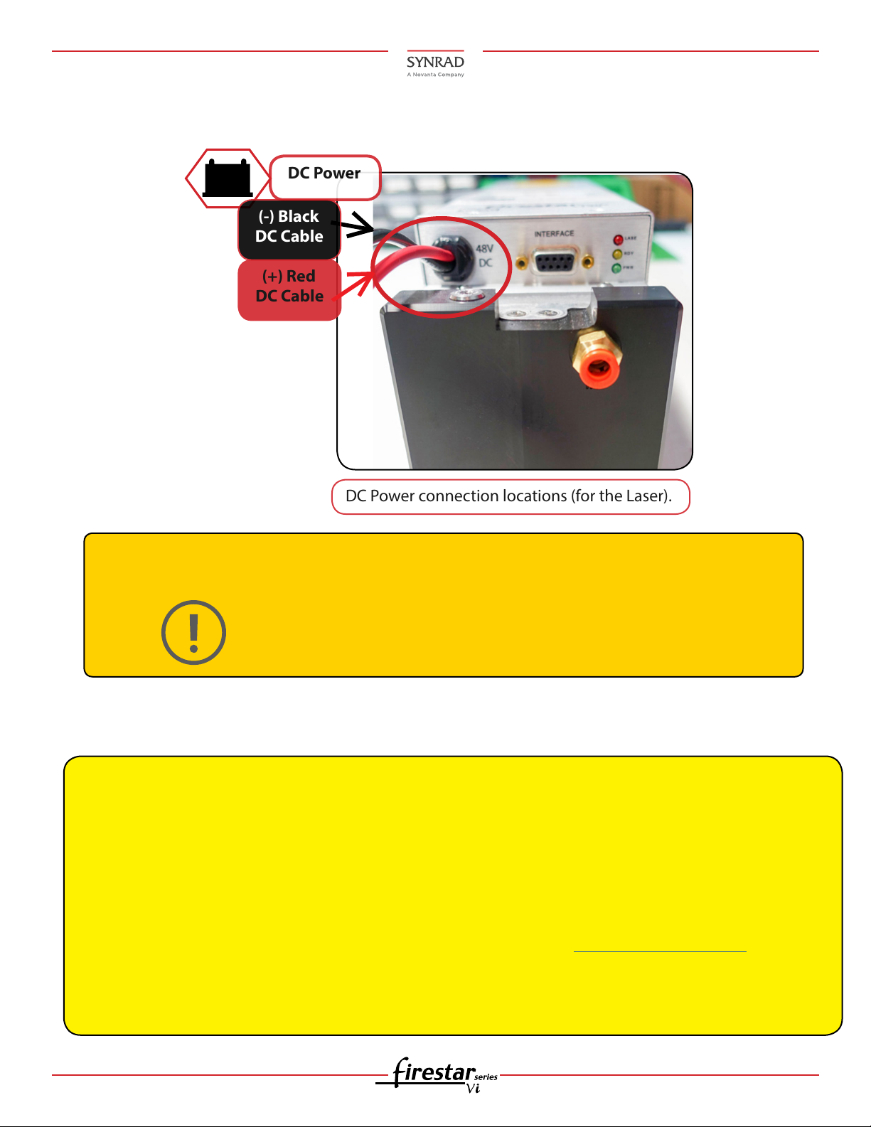
DC Power
(+) Red
DC Cable
(-) Black
DC Cable
DC Power connection locations (for the Laser).
Electrical Connections:
12. Connect the Laser negative (black) and the positive (red) DC power into the laser’s power supply.
Caution
Possible
Equipment
Damage
DC power:
Note:
The negative (–) side of the DC input to the laser is internally connected so that the laser chassis
serves as DC power ground. If you need to isolate the body of the laser from the equipment chassis
ground, use an insulating pad or lm and insulated mounting hardware.
OEM vi30/40 lasers can also be controlled from an alternate user-supplied Command signal source.
Refer to Controlling laser power in the Technical Reference chapter for control signal descriptions
and refer to DB-9 I/O connections, also in the Technical Reference chapter, for signal specifications
and connection details.
Be sure to also reference the technical reference chapter of the laser’s operation manual. When
applying 48 VDC, but before operating the laser, you must provide a Laser Enable input signal to
the DB-9 I/O connector. See DB-9 I/O connections in the Technical Reference chapter within the
operation manual for pinouts and signal descriptions.
Do not reverse polarity when connecting the DC Power cable to the vi30 laser.
Attach the red (+) wire(s) from the DC Power cable to the positive (+) 48 VDC
output terminal and attach the black (-) wire(s) from the DC Power cable to
the negative (-) 48 VDC output terminal. Refer to the drawings located on our
website.
10 vi30/40 Dual Cooled QSG Version 2.1
Page 11
Firestar™ vi30/40 Dual Cooled Laser Quick Start Guide
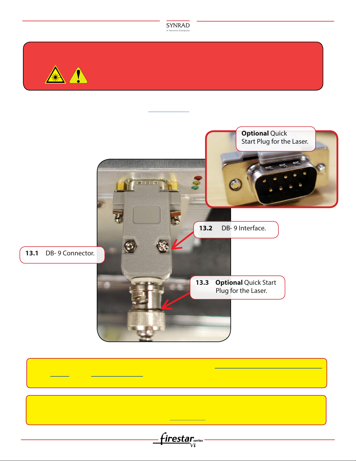
13.1 DB- 9 Connector.
13.3 Optional Quick Start
Plug for the Laser.
13.2 DB- 9 Interface.
Optional Quick
Start Plug for the Laser.
Control Connections:
Warning!
Serious Personal
Injury
13. If using the UC-2000 controller, see the UC-2000 QSG located on our website, then connect the
laser’s control DB-9/BNC interface to the laser. (See the following gures.)
The Quick Start Plug bypasses the laser’s safety interlock function,
potentially exposing personnel to hazardous invisible laser radiation.
Note:
Note: IF not using a SYNRAD controller for your laser, AND your OEM vi30/40 laser is put into service
for the rst time, OR it has been re-located and has not been sed yet in its new location,
functionality should be veried. Go to the next section.
If using a UC-2000 Universal Laser Controller, refer to the UC-2000 Laser Controller Quick Start
Guide and it’s Operator’s Manual for setup and operation instructions located on our website.
Continue below and to the next section.
11 vi30/40 Dual Cooled QSG Version 2.1
Page 12
Firestar™ vi30/40 Dual Cooled Laser Quick Start Guide
Control Connections (Continued):
Warning!
Serious Personal
Injury
Caution
Possible
Equipment
Damage
Always, use lockout/tagout for safety. Always wear safety goggles. Always
use shielded cable when connecting your PWM Command signal source to
PWM Positive/PWM Negative inputs.
In electrically-noisy environments, long lengths of unshielded wire act like
an antenna and may generate enough voltage to trigger uncommanded
lasing.
Do not reverse polarity when connecting DC power cables to your DC power
source. Reversed DC polarity will damage the lasers internal RF and control board
circuitry. Carefully follow the directions below to ensure that DC cable leads are
properly connected to the correct DC output terminals.
Turn o DC power before installing or removing any plug or cable from the DB-9
I/O connector. Ensure that user connections are made to the appropriate pins and
that the appropriate signal levels are applied. Failure to do so may damage the
laser.
Vi-Series lasers MUST be provided with a pre-ionizing “tickle” signal during
standby or laser “low” periods. This signal is automatically provided by SYNRAD
UC-2000 Universal Laser Controller.
A tickle signal keeps the plasma ionized during laser ‘low’ periods and facilitates plasma breakdown and pulse-to-pulse delity. Damage to or malfunction of
the laser may occur if this, or equivalent drive signals are not provided.
If the laser has been “OFF” or the tickle has not been applied for any length
of time apply the tickle signal for at least two seconds before applying any PWM
command signal.
Controlling your laser without a UC-2000 controller:
Important
Note:
Before your OEM vi30/40 laser is put into service for the rst time, its functionality
should be veried.
Proceed to the next section or the following procedure if you are not utilizing the UC2000 controller to verify the laser system is operating at optimum performance.
12 vi30/40 Dual Cooled QSG Version 2.1
Page 13
Firestar™ vi30/40 Dual Cooled Laser Quick Start Guide
Initial startup of your OEM vi30/40 laser:
Note:
Important
Note:
The laser’s control board does not incorporate a built-in tickle generator nor the applied PWM signals. If
you are not using a SYNRAD® UC-2000 Universal Laser Controller to operate the laser, you must provide a
5 kHz, 1 µs tickle pulse between applied PWM signals. ‘See Controlling laser power’ in the laser’s Operation
Manual Technical Reference chapter for tickle signal descriptions.
The OEM vi30/40 laser requires a DC power supply capable of providing 48 VDC at minimum (12 A (vi30) 20A
(vi40) peak for less than 1 ms). To connect the vi30/40 laser to a 48 VDC power supply, perform the following
steps:
14. If the laser has a Diode Pointer installed, remove its aperture dust cover.
You will need to provide a tickle signal and a pulse width modulated (PWM) Command signal to
the laser’s CTRL input connector. Refer to Controlling laser power in the Technical Reference chapter in your laser’s Operation Manual for tickle and PWM Command signal descriptions.
When performing the initial start-up sequence, check that the factory-installed DB-9 jumper plug is installed. If not, you must provide the required Remote Interlock and Remote
Keyswitch signals to the DB-9 Connector. See the laser’s Operation Manual for DB-9 connections, pinouts and signal descriptions.
Verify your laser power to ensure output is consistant with the rating of your particular model.
Ensure that all personnel in the area are wearing protective eye-wear!
15.
16. Assure the red self-adhesive aperture seal has been removed from the laser’s faceplate.
17. Verify that input AC power to the DC power supply is physically locked out or disconnected.
18. Place an appropriate beam block 61cm (24 in) from the laser aperture, in this case a power meter,
(such as SYNRAD® PW-250 Power Wizard®) to verify that output power is consistent with the power
rating for your particular model. Beam block prevents the beam from traveling beyond the work
area.
Note:
19. Ensure your controller is set to provide a 1 µs square wave tickle pulse at a frequency of 5 kHz
during any 200-µs measurement period where a PWM signal is not applied.
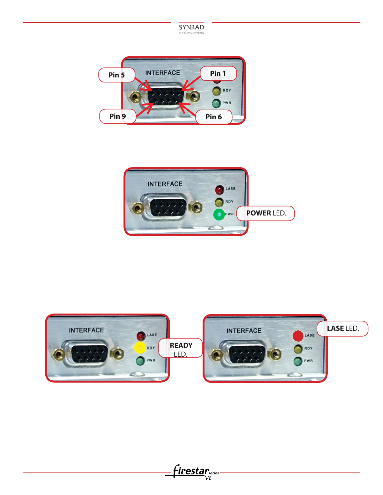
20. Connect the output of your PWM controller to PWM Positive (Pin 1) on the laser’s DB-9 I/O connec-
tor and connect the ground or return of the Controller to PWM Negative (Pin 6). Reference the la ser’s Operation Manual Technical Reference section for DB-9 connections. See the following gure.
If using water for cooling, see the laser’s Operation Manual for specications, review the
water cooling sections within this guide and the laser’s operation manual.
13 vi30/40 Dual Cooled QSG Version 2.1
Page 14
Firestar™ vi30/40 Dual Cooled Laser Quick Start Guide
Pin 1
Pin 5
Pin 6
Pin 9
POWER LED.
LASE LED.
READY
LED.
Initial Start up without a UC-2000 Controller (Continued):
21. Restore power to the laser and turn on the +48 VDC power supply. Turn on the +48 VDC power
supply. The laser’s PWR LED should illuminate green. After a ve-second delay, lasing is enabled
when a PWM Command signal is received.
22. Set your PWM controller to a frequency of 5 kHz (at a +5 volt level) and ensure that the controller’s
duty cycle is set to zero percent output (0.0%).
23. Apply a Laser Enable signal to the DB-9 I/O connector. The yellow RDY lamp turns on to indicate
that, after a ve-second delay, lasing is enabled when a PWM Command signal is received. Lase
LED will illumate red.
24. If your laser fails to lase, reference the laser’s Troubleshooting Section within the Operation Manual,
SYNRAD website for more information or contact SYNRAD support.
14 vi30/40 Dual Cooled QSG Version 2.1
 Loading...