

Page 1
FEATURES
3 Transmitter/receiver built into same unit
3 Six user-selectable sensitivity levels
3 5m to 70m (use BEAMLRK beyond 70m) protection range
3 Removable plug-in terminal blocks
3 Digital display – no special tools required
3 Built-in automatic gain control compensates for signal
deterioration from dust buildup
3 Optional remote test station
3 Optional long-range kit (BEAMLRK) for applications in
excess of 70m
3 Optional multi-mount (BEAMMMK) providing ceiling or wall
mount capability with increased angular adjustment
PRODUCT DATA SHEET
SS-BEAM1224
Conventional Beam Detector
Installation Guide
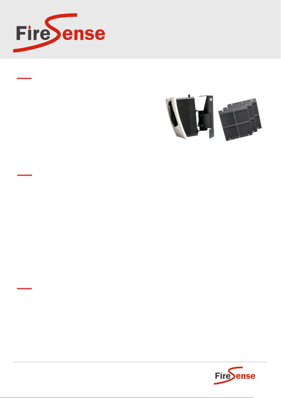
PRODUCT DESCRIPTION
The FireSense SS-BEAM1224 is a conventional projected beam smoke sensor. It is uniquely suited for
protecting open areas with high ceilings where other methods of smoke detection are difficult to install and
maintain. Alignment is quickly accomplished via an optical sight and a 2-digit signal strength meter incorporated
into the product.
Listed for operation from -30ºC to 55ºC, the SS-BEAM1224 can be used in open area applications to provide early
warning in environments where temperature extremes exceed the capability of other types of smoke detection.
The SS-BEAM1224 consists of a transmitter/receiver unit at the head end and a reflector. When smoke enters the
area between the unit and the reflector, it causes a reduction in the signal and when the smoke level reaches the
predetermined threshold, an alarm is activated.
The SS-BEAM1224 has four standard sensitivity selections along with two Acclimate settings. When either of the
two Acclimate settings are selected the detector will automatically adjust its sensitivity using advanced software
algorithms to select the optimum sensitivity for the specific environment.
CABLING REQUIREMENTS
SS-BEAM1244
3 Requires 2 core for 24Vdc
3 Requires 2 core for initiating alarm contact
NSW
18-20 Brookhollow Ave
NORWEST 2153
02 8850 2888
sales@firesense.com.au
VIC
Unit 4, 297 Ingles St
PORT MELBOURNE 3207
03 9646 4557
salesvic@firesense.com.au
QLD
Unit 2, 225 Queensport Rd North
MURARRIE 4172
07 3890 8842
salesqld@firesense.com.au
www.firesense.com.au
Page 2

PRODUCT DATA SHEET
Conventional Beam Detector
TECHNICAL SPECIFICATIONS
Protection range 5m to 70m (70m to 100m long range kit)
Adjustment angle ± 10º horizontal and vertical
Sensitivity
(Refer to Sensitivity Chart on page
6 of Installation Guide)
Alarm indicator Local red LED and remote alarm
Trouble indicator Local yellow LED and remote trouble
Normal indicator Local flashing green LED
Temperature -30ºC to 55ºC
Humidity 10% - 93% Relative humidity non-condensing
Voltage 10.2 to 32Vdc
Average standby current 17mA maximum
Alarm current 38.5mA maximum
Fault current 8.5mA maximum
Detector dimensions 254mm H x 191mm W x 84mm D
Reflector dimensions 5m to 70m 200mm x 230mm
Level 1 – 25% total obscuration
Level 2 – 30%
Level 3 – 40%
Level 4 – 50%
Acclimate Level 1 – 30-50%
Acclimate Level 2 – 40-50%
Over 70m 400mm x 460mm
SS-BEAM1224
Installation Guide
PRODUCT DESCRIPTION
Installation/Alignment
The alignment is divided into four steps: coarse alignment, fine adjustment, final gain adjustment, and final
verification. It is necessary for all four steps to be executed properly to ensure proper alignment of the product.
Pre-Alignment Checklist
3 Ensure that both the detector and reflector are mounted securely to stable surfaces
3 Ensure that all wiring is correct
3 Ensure that terminal blocks are fully seated into their receptacles on the detector
3 Complete any wiring dressing to minimize movement to the detector once the alignment procedure is
completed
3 Ensure that the appropriate number of reflectors are used for the installed distance. Distances between
70 - 100m require additional reflectors (4 total). The BEAMLRK accessory should be used in these cases.
3 Ensure that the line of sight between the detector and reflector is clear and that reflective objects are not
too near.
NSW
18-20 Brookhollow Ave
NORWEST 2153
02 8850 2888
sales@firesense.com.au
VIC
Unit 4, 297 Ingles St
PORT MELBOURNE 3207
03 9646 4557
salesvic@firesense.com.au
QLD
Unit 2, 225 Queensport Rd North
MURARRIE 4172
07 3890 8842
salesqld@firesense.com.au
www.firesense.com.au
Page 3
PRODUCT DATA SHEET
SS-BEAM1224
Conventional Beam Detector
Installation Guide
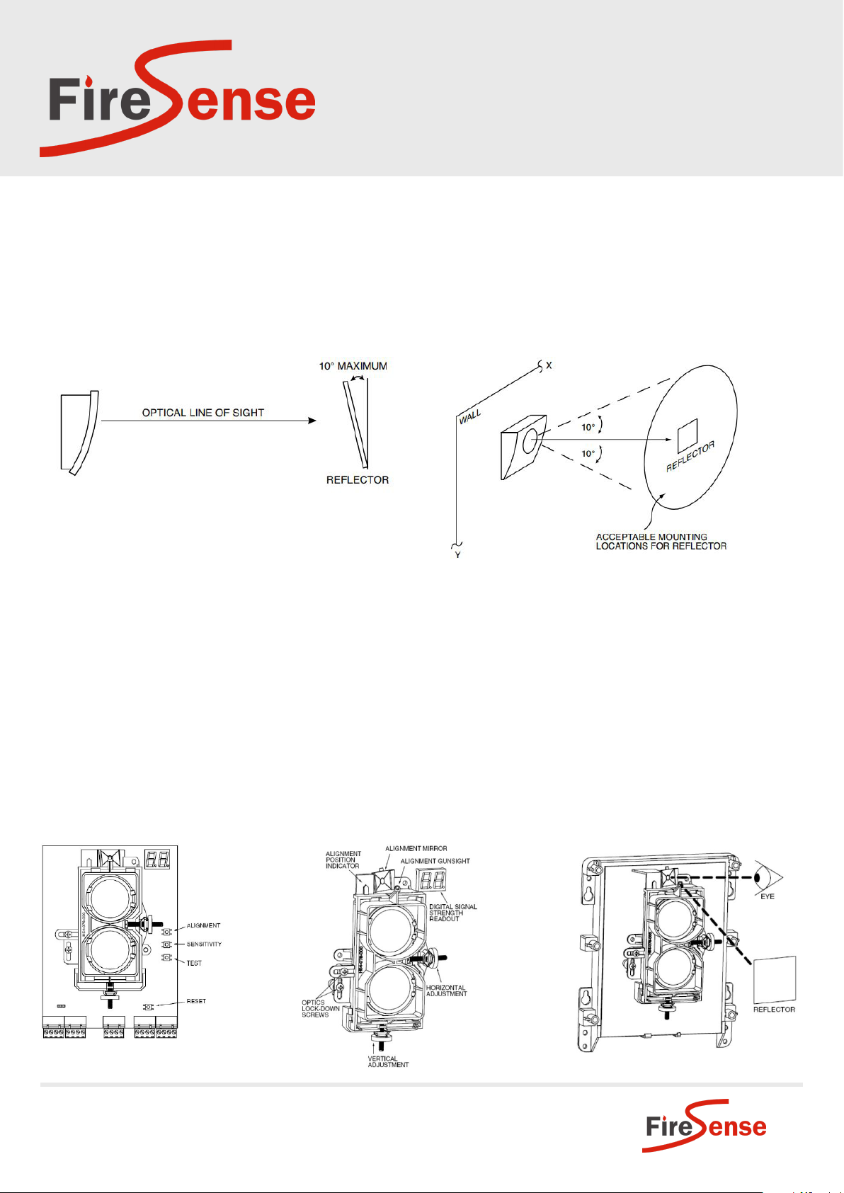
3 Ensure that both the detector and reflector are mounted within their operational parameters for off axis
angles (see below)
3 Disable the zone or system to prevent unwanted alarms before applying power
3 Ensure power to the detector is “ON”
You are now ready to begin the alignment procedure.
Reflector Mounting Guidelines
Step 1. Coarse Alignment
Refer to Figures 2 and 3 for this step.
1. Ensure that both of the optics lock-down screws are loosened so that the optics will move freely.
2. Looking through the alignment mirror, at both the alignment sight and reflector simultaneously, locate the
position of the reflector in the optical sight. This step will require some practice. It is necessary to train your
eyes to shift focus between the reflector and the mirror in order to locate the reflector. If the distance between
the reflector and the detector is large it is helpful to place a brightly coloured object on the wall near the
reflector to aid in seeing the reflector in the alignment mirror.
3. Once the reflector has been located, begin to adjust both the horizontal and vertical alignment knobs so that
the reflector becomes centred in the alignment mirror. Take care in this step. If the optics are incorrectly aligned
in this step, it will not be possible to proceed with the fine adjustment step.
Figure 1: Switch Locations Figure 2: Alignment Adjustment Locations Figure 3: Coarse Alignment Procedure
NSW
18-20 Brookhollow Ave
NORWEST 2153
02 8850 2888
sales@firesense.com.au
VIC
Unit 4, 297 Ingles St
PORT MELBOURNE 3207
03 9646 4557
salesvic@firesense.com.au
QLD
Unit 2, 225 Queensport Rd North
MURARRIE 4172
07 3890 8842
salesqld@firesense.com.au
www.firesense.com.au
Page 4

PRODUCT DATA SHEET
SS-BEAM1224
Conventional Beam Detector
Installation Guide
Step 2. Fine Adjustment
Refer to Figures 1-3 for this step.
In this step you will be fine-tuning the optics to the reflector. To provide feedback of the signal level coming
from the reflector the dual digital display readout will be used. Due to the large distance range that the detector
can operate over it is necessary that the detector operate with many different settings of “electronic amplifier
gain”. The detector is capable of determining the appropriate gain setting and then setting it itself via on-board
processing algorithms. There are no external gain settings on the detector that must be set by the operator.
Periodically throughout the fine adjustment step the detector will need to re-adjust its “electronic amplifier gain”
setting. When this occurs it will be indicated by the dual digital readout as “- -”. When this occurs, cease any further
adjustment until the display again reads a number value.
1. Ensure that neither you nor any other objects are in the line of sight between the detector and the reflector.
2. Depress the Alignment switch once. Both the digital display and the yellow LED should turn on indicating
that alignment mode has been entered. The display should begin reading “- -” signifying an electronic gain
adjustment. After a few moments the display will indicate a numeric value near 20. If the display reads “Lo”
then the detector is not receiving enough light from the reflector. Go back and repeat the coarse alignment step
and verify that the proper number of reflectors is used for the installed distance.
Note: The display will continue to read “Lo” until the detector receives enough light from the reflector to continue
with the fine adjustment step.
Note: In alignment mode (indicated by the yellow LED and the numeric display) the sensitivity select and test
switches are disabled.
3. With the display reading a numeric value, begin adjusting the horizontal and vertical alignment knobs one at
a time in the direction that increases the numeric signal level on the display. Continue adjusting each axis one
at a time going back and forth between them until a peak value is indicated. If a value of 90 is achieved, the
detector will re-adjust the electronic gain once again. This will be indicated by a “- -” reading on the display.
When this happens halt any further adjustment until the display again reads a numeric value. This process may
occur more than once during the fine adjustment step.
Note: Each time the display reads a value of 90 or greater the detector will reduce the electronic gain. Each time
the display reads a value of 10 or less the detector will increase the electronic gain.
4. Once satisfied that it is not possible to achieve a higher reading on the display, depress the alignment switch
to complete the fine adjustment step. The digital display readout will turn “OFF” and the yellow LED will remain
“ON”.
Note: It may not be possible to achieve a value near 90 on the display during the last adjustment iteration. The
final value of the display will not likely be near 90. This is normal. It is due to the detector reducing its electronic
gain each time a value of 90 is achieved. When this occurs the detector resumes with less electronic gain than
previously when 90 was achieved. Less gain makes it more difficult to achieve higher values. Final values anywhere
between 20 and 90 are acceptable if no further increase can be achieved.
Note: The alignment procedure is not complete yet. At this time it is possible to set the sensitivity of the detector
using the sensitivity switch and digital display. See the Sensitivity Selection section of this manual for further
details.
NSW
18-20 Brookhollow Ave
NORWEST 2153
02 8850 2888
sales@firesense.com.au
VIC
Unit 4, 297 Ingles St
PORT MELBOURNE 3207
03 9646 4557
salesvic@firesense.com.au
QLD
Unit 2, 225 Queensport Rd North
MURARRIE 4172
07 3890 8842
salesqld@firesense.com.au
www.firesense.com.au
Page 5

Step 3. Final Gain Adjustment
In this step, the detector will electronically adjust its internal gain
one final time. It is necessary to complete this step with the outer
housing installed since the housing will change the amount of light
received from the reflector.
1. Tighten the optics lock down screws so the optics are secure.
2. Install the outer housing of the detector. The housing is installed
by tightening four screws, one in each corner of the housing. The
screws are captivated in the plastic of the housing and cannot
fall out during assembly.
Note: The housing contains a gasket seal that protects the detector
circuitry from corrosion and moisture sources. To ensure that the
gasket seal performs correctly it is necessary to fully tighten all four
of the screws that hold the outer housing in place.
PRODUCT DATA SHEET
SS-BEAM1224
Conventional Beam Detector
Installation Guide
3. Remove the protective film from the front surface of the outer housing.
4. To initiate the final electronic gain adjustment, the reset switch must be depressed. Once depressed the yellow
LED will begin to blink. This indicates that the detector is adjusting the electronic gain setting. Once complete,
the yellow LED will stop blinking and the green LED will begin blinking. This indicates that the gain adjustment
was successful.
Note: Use caution not to block the line of sight between the detector and reflector in this step.
5. Install the outer aesthetic ring by snapping it onto the outer housing.
Note: If the outer aesthetic ring has been painted ensure that the paint is completely dry before proceeding with
this step.
Step 4. Final Verification
This step is required to ensure the detector has been setup correctly and will detect smoke at the proper sensitivity
level.
1. With the detector functioning (indicated by the green LED blinking), completely block the reflector with an
opaque material. (Due to the high optical efficiency of the reflector, the selection of the opaque material used
to block the reflector is not critical. Acceptable materials include, but aren’t limited to, this manual or the
cardboard packaging inserts.) The detector should enter the trouble condition (indicated by the fault relay and
the yellow LED (see Appendix I). If the detector does not enter the trouble condition there is a problem with the
installation refer to the troubleshooting section in Appendix I for further assistance.
2. Complete a sensitivity test of the detector. Refer to the Sensitivity Testing section of this manual for the
appropriate procedure.
3. If the orange sticky paper was used to aid in the location of the reflector in the alignment mirror it should
be removed now. It is no longer necessary. Congratulations. You have completed the final installation and
alignment procedure.
NSW
18-20 Brookhollow Ave
NORWEST 2153
02 8850 2888
sales@firesense.com.au
VIC
Unit 4, 297 Ingles St
PORT MELBOURNE 3207
03 9646 4557
salesvic@firesense.com.au
QLD
Unit 2, 225 Queensport Rd North
MURARRIE 4172
07 3890 8842
salesqld@firesense.com.au
www.firesense.com.au
Page 6

PRODUCT DATA SHEET
SS-BEAM1224
Conventional Beam Detector
Installation Guide
Sensitivity Selection
The detector has six sensitivity selections. Each of these selections is only acceptable over a specific distance
separation between the detector and the reflector per UL268. The chart below is used to determine which
selections are acceptable for your installed distance. The sensitivity of the detector can be set only when the
housing is removed and the detector is not in the fine adjustment step of the alignment mode, indicated by the
illumination of the dual digital display. To set the sensitivity depress the sensitivity button one time (see Figure
1). Once the switch is pressed the digital display will illuminate and read the current sensitivity setting in percent
obscuration. To change the sensitivity continue to depress the sensitivity switch until the desired setting is achieved.
The digital display will turn off automatically if no further switch presses occur.
In addition to the four standard sensitivity selections the detector has two Acclimate settings. When either of
these settings is chosen the detector will automatically adjust its sensitivity using advanced software algorithms to
select the optimum sensitivity for the environment. The sensitivity will be continuously adjusted within the ranges
specified in the chart below.
Sensitivity Setting Percent Obscuration Display Reading
Acceptable Distance
Between Detector &
Reflector (Feet)
Acceptable Distance
Between Detector &
Reflector (Meters)
Level 1 25 25 16.4 - 120 5.0 - 36.6
Level 2 30 30 25 - 150 7.6 - 45.7
Level 3 40 40 60 - 220 18.3 - 67
Level 4 50 50 80 - 328 24.4 - 100
Acclimate Level 1 30-50 A1 80 - 150 24.4 - 45.7
Acclimate Level 2 40-50 A2 80 - 220 24.4 - 67
Sensitivity
Total obscuration can be converted to percent per foot,
assuming uniform smoke density for the entire length of the
beam. The chart on the right converts total obscuration to
percent per foot for all acceptable sensitivity settings.
Sensitivity Testing
Detectors must be tested after installation and following periodic maintenance. The sensitivity of the BEAM1224/
BEAM1224S may be tested with a calibrated Test Filter (Reflector Test Card) or the local test switch on the
transmitter/receiver unit.
Note: Before testing, notify the proper authorities that the smoke detector system is undergoing maintenance, and
therefore the system will be temporarily out of service. Disable the zone or system undergoing maintenance to
prevent unwanted alarms.
Note: Before testing the detector, check for the presence of the flashing green LED at the receiver, making sure not
to disturb or block the beam. If it does not flash and the detector is not in trouble or alarm, power has been lost to
the detector (check the wiring).
NSW
18-20 Brookhollow Ave
NORWEST 2153
02 8850 2888
sales@firesense.com.au
VIC
Unit 4, 297 Ingles St
PORT MELBOURNE 3207
03 9646 4557
salesvic@firesense.com.au
QLD
Unit 2, 225 Queensport Rd North
MURARRIE 4172
07 3890 8842
salesqld@firesense.com.au
www.firesense.com.au
Page 7

Conventional Beam Detector
APPENDIX I. OPERATION MODES AND TROUBLESHOOTING GUIDE
PRODUCT DATA SHEET
SS-BEAM1224
Installation Guide
Modes Red Yellow Green
Normal Off Off Blink Off
On, Relative amount
Alignment Off On Off
Alarm On Off Off Off
Trouble-Drift
Comp Elevated
Signal
Trouble-Drift
Comp Reduced
Signal
Trouble-Signal
Over Range
Trouble-Beam
Blockage
Response
Initialisation-
Power On
Initialisation-
Alignment Exit
Local Test
(BEAM1224S)
Pass Result
Local Test
(BEAM1224S)
Fail Result
Local Test
(BEAM1224)
Fail Result
Local Test
(BEAM1224)
Pass Result
Off
Off
Off
Off
Off
Off
On
Off
Off
On
3 Quick
Blinks
2 Quick
Blinks
2 Quick
Blinks
4 Quick
Blinks
Blink Until
Complete
Blink Until
Complete
Blinking the
amount of
drift used
On until
reset or
time-out
Per fault
mode
Blinking the
amount of
drift used
of signal 0-99, or - - if
automatic gain reset-
ting, or Lo if signal is
Blink Off
Blink Off
Blink Off
Off Off Beam blockage Open Off Open
Blink Off
Blink Off
Off Off
Blink Off
Blink Off
Off Off
Dual Digital
Dispaly Readout
too low
Initiating Means
Successful completion
of initialisation or
detector reset
Alignment switch Close Off Open
Smoke, test filter,
RTS451/KEY or
RTS151/KEY
Long term drift refer-
ence out of range
Long term drift refer-
ence out of range
Increase of reflected
signal
Apply power from
discharged state
Depressing RESET
switch after alignment
RTS451/KEY or
RTS151/KEY
RTS451/KEY or
RTS151/KEY
RTS451/KEY or
RTS151/KEY
RTS451/KEY or
RTS151/KEY
Alarm Controls
Alarm Remote
Open
Open
Open On Close
Open Off Open
Open Off Open Clean detector and reflector
Open Off Open
Open Off Close
Open Off Close
Close On Close
Open Off Open
Open Off Open
Open On Close
Off Close
Fault
Contacts
Comments &
Troubleshooting Tips
- Sunlight into detector or reflector
- Re-align detector
Inspect line of sight between de-
tector and reflector for reflective
objects in the pathway
- Remove blockage
- Faulty unit
Detector remains in alarm until
reset or time-out
Detector remains in fault until
reset or time-out
If local test fails will already be
in fault
Blinks output by yellow LED and
Remote Trouble Output once the
device has passed a local remote
test (tables to the right):
NSW
18-20 Brookhollow Ave
NORWEST 2153
02 8850 2888
sales@firesense.com.au
VIC
Unit 4, 297 Ingles St
PORT MELBOURNE 3207
03 9646 4557
salesvic@firesense.com.au
Percent the detector has drifted Number of blinks output
<10% None
<20% 1
<30% 2
<40% 3
<50% 4
QLD
Unit 2, 225 Queensport Rd North
MURARRIE 4172
07 3890 8842
salesqld@firesense.com.au
Percent the detector has drifted Number of blinks output
<60% 5
<70% 6
<80% 7
<90% 8
<100% 9
www.firesense.com.au
 Loading...