

Page 1
Page 2
DANGER
TOOLS AND PARTS NEEDED FOR ASSEMBLY
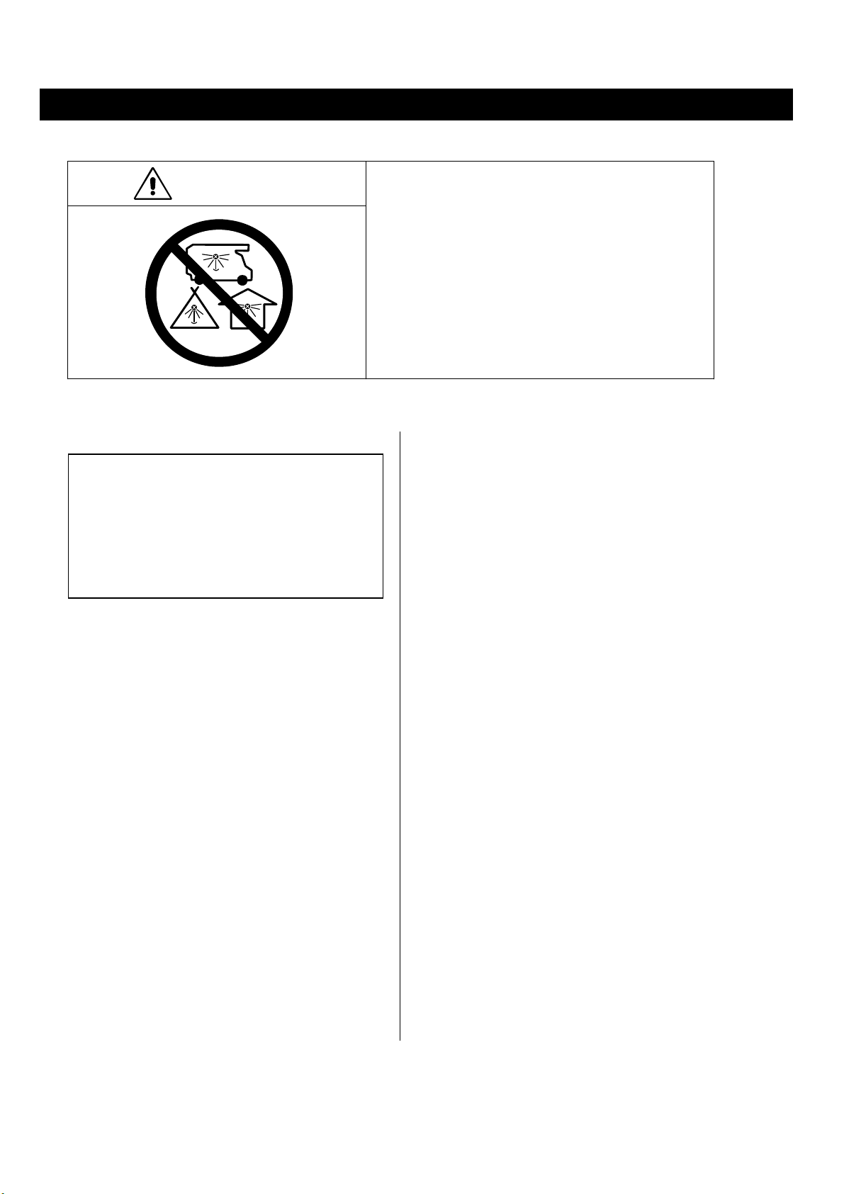
CARBON MONOXIDE HAZARD
This appliance can produce carbon monoxide
which has no odor.
Using it in an enclosed space can kill you.
Never use this appliance in a enclosed space
such as a camper, tent, car or home.
WARNING:Improper installation, adjustment,
alteration, services or maintenance can cause
injury, death or property damage.
Read the installation, operating and
maintenance instructions thoroughly before
installing or servicing this equipment.
WARNING:
FOR OUTDOOR USE ONLY.
Cylinders to be used must be constructed and
marked in accordance with US DOT
specifications.
Storage indoors is permissible only if the
cylinder is removed.
The unit should be secured or moved indoors
if winds exceed 19.5mph.
Tools needed
Adjustable opening 8’’long
Philips head screwdriver
Leak detection solution (instructions on how to
make solution are included in Step 11)
For questions, replacement parts, service
please call Well Traveled
help or other assistance,
Living’s Service Hotline at 1-866-985-7877
(1-866-WTL-SUPP) or email
cservice@welltraveled.net.
wrench
Note:
Use only 20lb. LPG tank (not supplied).
Use only CSA regulator with 1.2m gas
hose (included).
Page 3
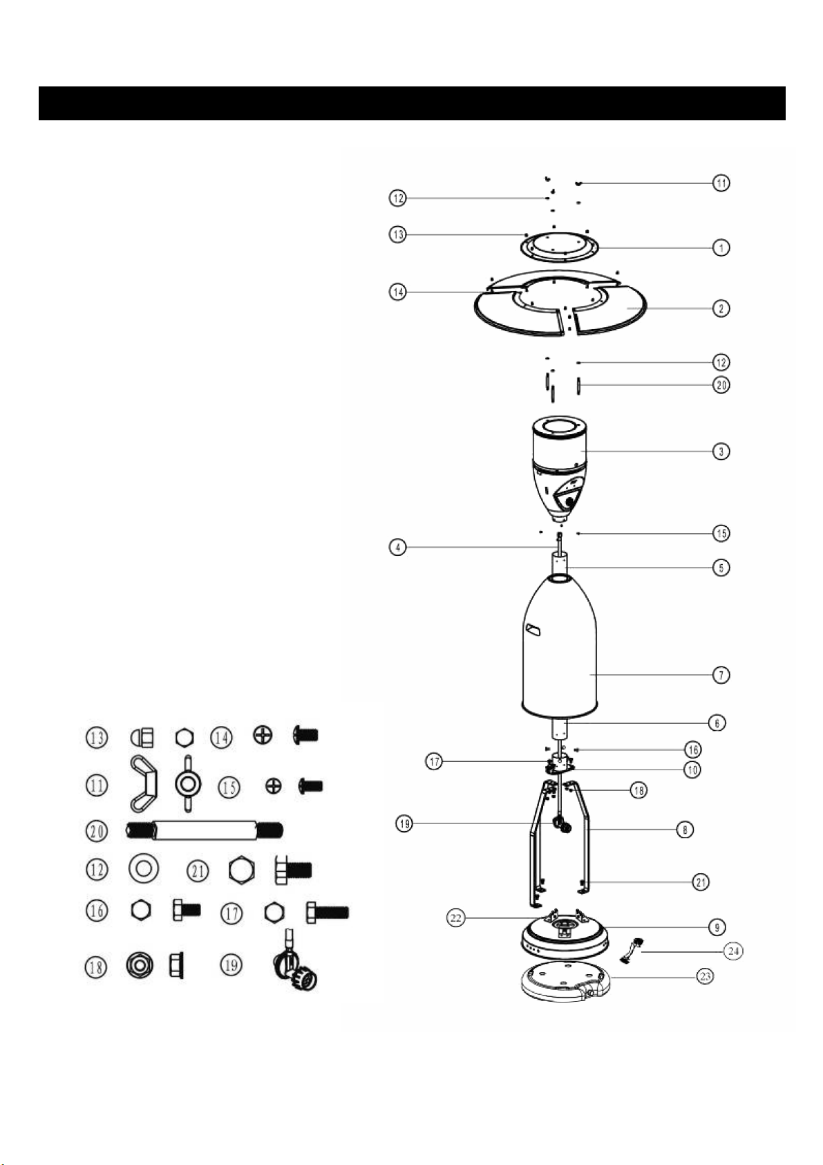
1 Center Reflector Cap
1
●
3 Reflector Pieces
2
●
1 Head Assembly
3
●
1 Gas Hose (attached to Regulator 19)
4
●
1 Upper Post
5
●
1 Lower Post
6
●
1 Cylinder Cover
7
●
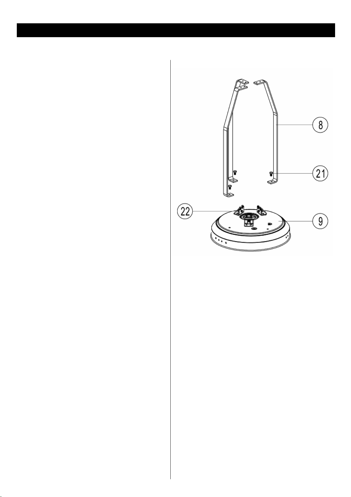
3 Post Mounts
8
●
1 Cylinder Base
9
●
1 Post Support
10
●
3 M8 Screw Cap
11
●
6 M8 Washers
12
●
9 M6 Screw Cap
13
●
9 M6x8 Bolts
14
●
4 M5x10 Bolts
15
●
4 M6x10 Bolts
16
●
6 M6X18 Bolts
17
●
6 M6 Screw Cap
18
●
1 Regulator (with Hose 4)
19
●
3 M8x90 Double Pointed Bolts
20
●
3 M8X16 Bolts
21
●
6pcs M6x12mm bolts for connection of
22
●
LPG cylinder fixed parts with base
Water Box (attached to Base 9)
23
●
Wheels
24
●
PARTS
Page 4

NOTE: PLEASE READ THE FOLLOWING SAFETY RULES
WARNING:
This appliance must only be used outdoors.
Using this product in an enclosed area may cause
injury, death or property damage.
Read the instructions before use.
This appliance must be installed in
accordance with such regulations as
are in force.
Do not use the heater in an explosive atmosphere.
Keep the heater away from areas where gasoline or other
flammable liquids or vapors are stored.
Prior to use check for damaged parts such as hoses,
regulators, pilot or
Warning: This appliance requires a gas hose and regulator.
Regularly check the gas hose and if necessary,
replace the gas hose.
Disconnect LPG cylinder before moving the heater.
Do not attempt to alter unit in any manner (Example:
using the heater without the top canopy
reflector or radiant screen).
Do not shorten the burner post assembly.
The appliance shall not be used in basements or below
ground level.
It must always be placed on a solid and level surface.
Always ensure there is ample fresh air ventilation.
For outdoor use ONLY.
Maintain at least 50’’ top and side clearance to combustible
materials and surfaces.
Never replace or substitute the regulator with any regulator
other than the factory suggested replacement.
Do not clean the heater with cleaners that are combustible
or corrosive.
Do not paint radiant screen, control pa
reflector.
Leak tests should be done with a soapy solution. NEVER
USE AN OPEN FLAME TO CHECK FOR LEAKS.
The LP Gas cylinder should be turned off when the
heater is not in use.
burner.
nel or top canopy
At least once a year, the unit should be inspected for
the presence of spiders, spider webs or other insects.
Check the heater immediately if any of the following
exist:
1. The smell of gas in conjunction with extreme yellow
colored tips of the burner flames.
2. The heater does not reach temperature.
3. The burner makes popping noises during use (a
slight popping noises is normal when the burner is
extinguished afer using).
The propane hose with regulator assembly shall be
located out of pathways where people may trip over it
or in areas where the hose may be subjected to
accidental damage.
Children and adults should be aware of the hazards of
high surface temperature and shall stay away to avoid
clothing burn or ignition.
Young children should be carefully supervised when
they are in the area of the heater.
Clothing or other flammable material should not be
hung from the heater, or placed on or near the heater.
Any guard or other protective device removed for
servicing the heater must be replaced prior to
operation.
Installation and repair should be done by a qualified
service person. The heater should be inspected before
use and cleaning may be required at least once a year
or as necessary. It is imperative that control
compartment, burner and circulating air passageways
of the heater be kept clean.
Keep the appliance area clear of combustible
materials such as gasoline and other flammable
vapors and liquids. Do not obstruct the flow of
combustion and ventilation air.
Keep the ventilation opening of the cylinder enclosure
free and clear of debris.
PRECAUTIONS
Save these instructions! Retain in in a safe place for future reference.
Page 5
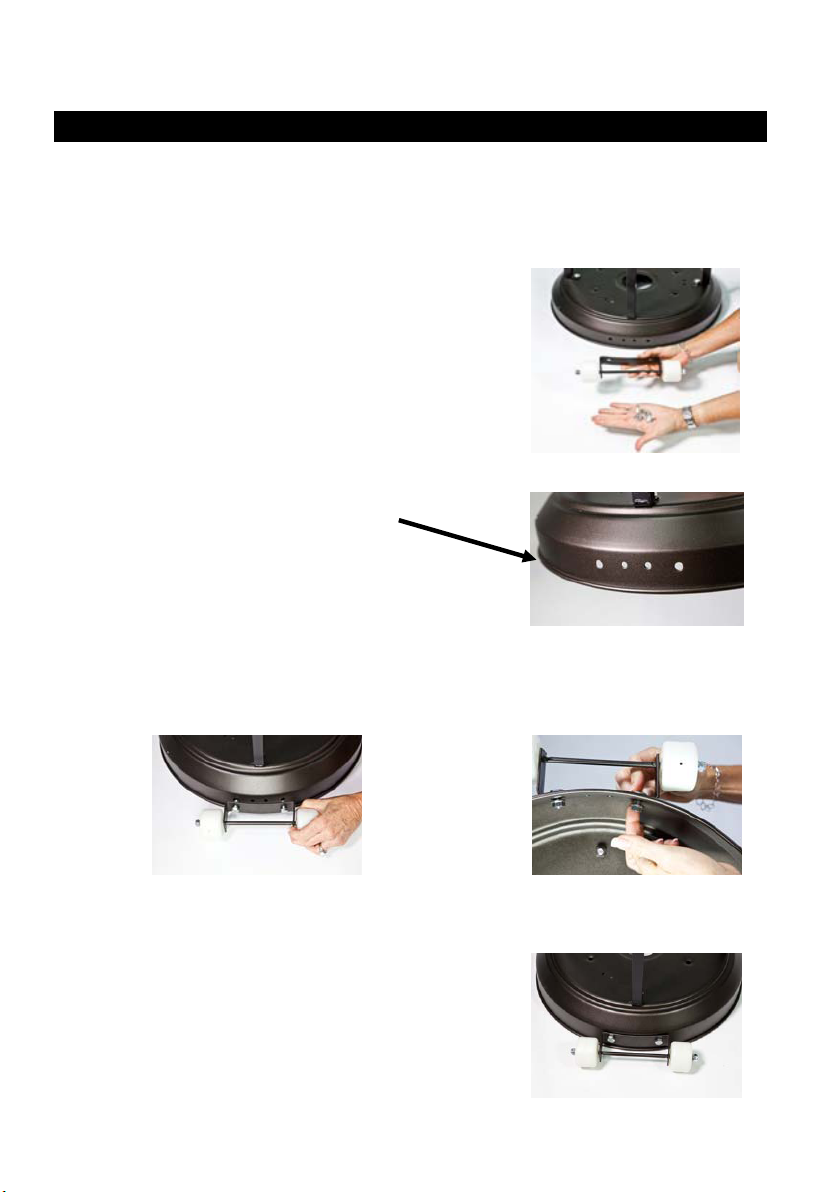
ATTACHING WHEEL ASSEMBLY
Step 1
1-1. Locate Wheel Assembly (24) and 2 nuts/bolts contained in
plastic bag with Wheel Assembly (Fig. 1).
Step 2
ASSEMBLY
Fig. 1
2-1. Turn Base (9) so that holes for attachment of
Wheel Assembly are facing you (Fig. 2).
2-2. Align holes in Wheel Assembly (24) with
holes on Base (9) (Fig. 3).Insert bolts through both sets of holes
and secure nuts on end of bolt (Fig. 4).
Fig. 3 Fig. 4
Step 3
3-1. Wheel Assembly (24) should now be attached to Base (9)
as shown (Fig. 5).
Fig. 2
Fig. 5
5
Page 6
ASSEMBLY
WARNING:
Proper assembly is the responsibility of the installer.
Step 1
Attach 3pcs LPG cylinder fixed parts on the base
with 6pcs M6x12mm bolts.
Attach
Place the post mounts on the top of cylinder base,
and connect them using 3pcs M8x16 bolts.
post mounts to cylinder base:
STEP 1
Page 7

Step 2
Attach post support to post mounts:
Place the post support on the top of post
mounts and attach to post mounts using 6pcs
M6x18 screw bolts and 6pcs M6 screw caps.
ASSEMBLY
STEP 2
Step 3
Attach lower post to base assembly:
Attach the lower post to the post mounts using
4pcs M6x10 bolts.
STEP 3
Page 8

ASSEMBLY
Step 4
Attach upper post to lower post:
Screw the upper post to the lower post as
illustrated by turning in a clockwise
direction until securely tightened.
Step 4
Step 5
Attach cylinder cover to post mounts.
Step 5
Page 9

Step 6
Attach double pointed bolts to head assembly:
Attach M8x90 double pointed bolts (3pcs) to head
assembly.
ASSEMBLY
Step 7
Attach the gas hose to head assembly:
Route the gas hose up through the post and out of top,
then connect to the head assembly by turning in a
clockwise direction. NOTE: For secure connection,
use a wrench to tighten.
Finally connect the head assembly with post with 4pcs
M5x10 bolts.
Step 7
Page 10

ASSEMBLY
Reflector (#2) is comprised of 3 – outer pieces and 1 – center piece. Locate all 4 pieces of Reflector (#2) which are
wrapped in bubble wrap. Unwrap and remove all pieces and peel off the protective blue plastic on each piece.
Locate 9 bolts and 9 cap nuts in the plastic bag. Align the 3 – outer pieces with the 1 – center piece and place
a bolt through the center hole on each piece as shown below. Tighten castle nut on each bolt.
Next, align the sides of each outer piece and the center piece and insert the next 3 bolts through both holes.
Tighten castle nuts on bolts.
Finally, insert bolt through holes located at outside edge of adjoining panels of the reflector side pieces
(3 bolts required) and tighten castle nuts on bolts.
10
Page 11

Step 8
Attach the reflector to the top head assembly:
Attach 3pcs M8 washers on the top of 3pcs double
pointed bolts. Place assembled reflector on the top of
double pointed bolts and secure with 3pcs M8washers
and 3pcs M8 wing nuts.
ASSEMBLY
Step 9
Connect gas hose to cylinder (20lb.cylinder is not supplied):
Attach regulator to cylinder.
Tighten securely.
Move cylinder to the plate of base assembly.
Note: The regulator with gas hose is supplied.
(Regulator model: T2-LL526)
Page 12

ASSEMBLY
Step 10
Put the cylinder on the base:
Attach the cylinder to the base with 3pcs M8x12
bolts and tighten it in order to prevent the cylinder
from moving.
Warning:
The cylinder used must include a collar to protect
the cylinder valve.
Do not store a spare LP Gas cylinder under or near
this appliance.
Never fill the cylinder beyond 80 percent full.
For appliances designed to use a CGA No.791
connection: Place the dust cap on the cylinder valve
outlet whenever the cylinder is not in use. Only
install the type of dust cap on the cylinder valve that
is provided with the cylinder valve. Other types of
caps or plugs may result in leakage of propane.
Step 10
Gas supply pressure: 25 to 250PSI
Note:
Step 11
Check for leaks:
Your patio heater has been checked at the factory
for all possible connection leaks. To check the
connection of the gas hose / regulator /cylinder:
1. Make leak solution by mixing 1 part liquid dish
soap and 3 parts water.
2. Spoon several drops(or use quirt bottle) of the
solution onto the gas hose /regulator and regulator
/cylinder connection.
3. Inspect the connections and look for bubbles.
4. If no bubbles appear, the connection is safe.
5. If bubbles appear, there is a leak. Loosen and
re-tighten this connection.
6. If leak continues, call a qualified service person.
7. Use of Teflon (plumber’s) tape on threads of
connections is recommended.
gas
Page 13

Step 12
Lower the cylinder cover onto cylinder base.
ASSEMBLY
Step 13
Disconnect cylinder when storing or transporting:
1. Turn off the heater.
2. Turn off the valve of the cylinder.
3. Lift the cylinder cover above the post mounts.
4. Loosen the screw of cylinder and regulator.
5. Disconnect the cylinder from regulator.
The installation must conform with local codes or, in the absence of local codes, with the most current version
of the National fuel gas code, ANSI Z223.1
Step 13
Page 14
WARNING: DO NOT attempt to operate heater until you have
read and understood all precautions.
Failure to do so can result in serious personal injury, death and/or
property damage.
Before turning gas supply ON
Your heater was designed and approved for OUTDOOR USE ONLY .
O NOT use it inside a building, or any other enclosed area.
D
Make sure surrounding areas are free of combustible materials, gasoline
and other flammable vapors or liquids.
Ensure that there is no obstruction to air ventilation.
Be sure all gas connections are tight and there are no leaks.
Be sure that access panels are clear of debris.
Be sure any component removed during assembly or servicing is
replaced an
Before Lighting
Heater should be thoroughly inspected before each use, and by a qualified
service person at least annually.
If relighting a hot heater, always wait at least 5 minutes.
Our heater is tested for quality assurance.
Ignition attempts should succeed 8 out of 10 attempts.
LIGHTING INSTRUCTIONS
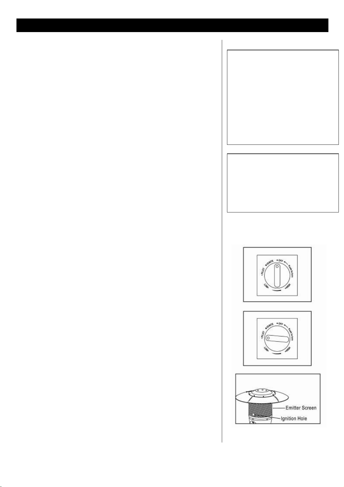
1. Turn the control knob to “OFF” position.
2. Fully open gas valve .
3. Push in gas control knob and turn counterclockwise to “IGNITE”
then to “PILOT” position. This will light the pilot.
If needed, keep depressing and turning control knob counterclockwise
until the pilot lights(you will hear 2 clicking noises).
4. Once the pilot is lit, continue to keep the control knob depressed for
at least 30
5. If pilot does not stay lit, repeat steps 3
6. If pilot still does not stay lit,
A . Push in gas control knob and turn counterclockwise to “IGNITE” then to
“PILOT”
B . Keep depressing the control knob and put long st
hole on the emitter screen to light the pilot
C . Repeat step 4.
7.
Push in and turn control knob counterclockwise to “LOW” position.
Release
push in the control knob and turn counterclockwise to the “HIGH”
position.
Note:
heater is operated. Normally the burner flame is blue, but a little yellow flame is
acceptable.
If flames extend beyond the emitter grid or there are black spots that have
accumulated
d fastened prior to starting.
seconds. After 30 seconds, release control knob.
and 4.
then:
ick lighter into the ignition
knob then turn to low. If you want a higher temperature,
The flame pattern at the emitter grid should be visually checked whenever
on the emitter grid or reflector, immediately turn off the
patio heater.
The heater should not be operated again until it has been serviced and
repaired by a qualified gas technician.
OPERATION
WARNING
FOR YOU SAFETY:
If at any time you are unable to light
burner and smell gas, wait 5 minutes
to allow gas to dissipate before
attempting to light heater. If after 1
minute you are unable to light burner,
wait 5 minutes and allow
flammable vapors to dissipate before
attempting to light heater again.
WARNING
FOR YOUR SAFETY:
DO NOT touch or move heater for at
least 45 minutes after use.
Allow emitter and dome to cool before
touching.
If you experience any ignition problem, turn off the heater and gas supply, and consult troubleshooting on page 19.
Page 15

CAUTION: Avoid inhaling fumes emitted from the heater’s first use.
Smoke and odor from the burning of oils used in manufacturing will
apper. Both smoke and odor will dissipate after approximately
30 minutes. The heater should NOT produce thick black smoke.
Note:
The burner may be noisy when initially turned on. To eliminate excessive
noise from the burner, turn the control knob to the “LOW” position, then
turn the knob to the level of heat desired.
When heater is ON:
Emitter screen will become bright red due to intense heat. The color is
more visible at night. Burner will display tongues of blue flame. These
flames should not be yellow or produce thick black smoke, indicating an
obstruction of airflow through the burner.
OPERATION
Operation Pressure Checked
If the flame is very small, this is because the supply pressure is not enough.
To Light:
1. Turn the control knob to “OFF” position.
2. Wait five minutes before attempting to relight pilot.
3. Repeat steps beginning with step 2 on page 14.
Before Leaving Heater Unattended:
1. Turn the control knob to “OFF” position and turn LPG cylinder to “OFF”
position.
2. Never leave the patio heater unattended while in use.
Shut Down Instructions
1. Push in and turn control knob clockwise to “OFF” position.
2. Turn LPG cylinder valve clockwise to “OFF” position when
heater is not in use.
Note: After use, some discoloration of the emitter screen is normal.
In the Event of Gas Leakage
1. Turn the control knob to “OFF” position.
2. Turn LP c
3. Wait 5 minutes to allow gas to dissipate.
4. If odor continues, immediately call gas supplier.
WARNING:
ylinder to “OFF” position.
Heater will be hot after use.
Handle with extreme care.
Page 16

WARNING: WHEN CERTAIN
MATERIALS OR ITEMS ARE LEFT
ABOVE, BESIDE, OR UNDER THIS
HEATER WHILE IN USE, THEY WILL
BE SUBJECT TO RADIANT HEAT AND
COULD BE SERIOUSLY DAMAGED.
This heater is primarily used for the heating
of outdoor patios, decks, spas, pools and open
working areas.
Always make sure that adequate fresh air
ventilation is provided. Follow the spacing
tolerances shown in Figure 1.
The minimum clearances, shown in Figure 1
must be maintained at all times.
LOCATION OF HEATER FOR USE
The installation must conform to local codes
or in the absence of local codes, with the
standard for the storage and handling of
liquid petroleum gases, ANS/NFPA 58-1986.
or most recent addition. (For Canada, wit
current CAN1-B149).
The heater must be placed on level firm ground.
Never operate in an explosive atmosphere. Keep
away from areas where gasoline or other flammable
liquids or vapors are stored or used.
h the
Page 17

Check your hose assembly:
The installation of fixed appliance shall only be carried out by competent
persons and be in accordance with the relevant codes of practice.
Warning: This appliance requires a ga
gas supplier and or product supplier. Regularly check the gas hose and if
necessary, replace the gas hose.
Prior to use, check for damaged parts such as hoses, regulator, pilot or burner.
Never replace or substitute the regulator with any regulator other than the
factory suggested replacement.
Check Your Flame:
The flame pattern at the emitter screen should be visually checked
whenever heater is operated.
Normally the burner flame is blue, but a little yellow flame is acceptable.
If flames extend beyond the emitter grid or there are black spots that have
accumulated on the emitter grid or reflector, immediately turn off the patio
heater. The heater should not be operated again until it has been serviced
and repaired by a qualified gas technician.
Cleaning Your Heater:
To enjoy years of outstanding perform
you perform the following maintenance activities a on regular basis:
1. Keep exterior surfaces clean
● Use warm soapy water for cleaning. Never use flammable or corrosive
cleaning agents.
● While washing your unit, be sure to keep the area around the burner
and pilot assembly dry at all times. If the gas control is exposed to water
in any way, do not try to use it. It must be replaced.
2. Air flow must be unobstructed. Keep controls, burner, and circulating
air passageways clean. Signs of possible blockage include:
● Gas odor with extreme yellow tipping of flame
● Heater does not reach the desired temperature
● Heater glow is exces
● Heater makes popping noises
3. Spiders and insects can nest in burner or orifices. This dangerous
condition can damage heater and render it unsafe for use. Clean
burner holes by using a heavy-duty pipe cleaner. Compressed air
may help clear away smaller particles.
4. Carbon deposits may create a fire hazard. Clean dome and emitter
screen with warm soapy water if any carbon deposits develop.
sively uneven
s hose and regulator. Check with your
ance from your heater, make sure
MAINTENANCE / STORAGE
WARNING
FOR YOUR SAFETY:
DO NOT touch or move heater for at
least 45 minutes after use.
Allow all burner elements to cool
before touching.
NOTE:
In a salt-air environment (such as
near an ocean) corrosion occurs
more quickly than normal.
Frequently check for corroded areas
and repair them promptly.
Page 18

MAINTENANCE / STORAGE
STORAGE:
Between uses:
Turn the control knob to “OFF” position.
Turn LPG cylinder to “OFF” position.
Store heater upright in an area sheltered from direct contact with
inclement weather (such as rain, sleet, hail ,snow, dust and debris).
If desired, cover heater to protect exterior surfaces and or help
prevent debris in air passages.
During periods of extended inactivity or when transporting:
Turn the control knob to “OFF” position.
Disconnect LPG cylinder and move to a secure, well-ventilated
location outdoors. Do NOT store in a location that will exceed
125 degrees F.
The propane cylinder must be stored outdoors in well-ventilated area,
and it must
or any other enclosed area.
Store heater upright in an area sheltered from direct contact with inclement
weather (such as rain , sleet, hail, snow and debris). If desired, cover heater to
protect surfaces and to help prevent debris in air passages.
be out of reach of children. Do not store in a building,garage,
NOTE:
Wait until heater is completely
cooled before covering.
Page 19

TROUBLESHOOTING
PROBLEM PROBABLE CAUSE SOLUTION
Pilot will not light
Pilot will not stay on
Burner will not light
Gas valve may be OFF Turn the gas valve ON
Fuel tank empty Refill LP gas tank
Orifice blocked Clean or replace orifice
Air in supply system Purge air from lines
Loose connection Check all fittings
Debris around pilot Clean dirty area
Loose connection Tighten connection
Thermocouple bad Replace thermocouple
Gas leak in line Check connection
Lack of fuel pressure Fuel tank is near empty
Pressure is low Fuel tank is near empty
Orifice blocked Remove, clean and replace
Control valve not ON Turn valve to ON
Thermocouple bad Replace thermocouple
Pilot light assembly bent or not in
correct location
Place pilot in proper position and
retry
Page 20

 Loading...