

Page 1

AFP-2800/2802
Fire Alarm Panel
OPERATION, INSTALLATION &
PROGRAMMING MANUAL
Revision 6.00
3rd May 2013
ECN13-0023
Manufactured by:
Approvals:
Australian Standard AS4428.1 1998
ActivFire Listing No: AFP-1801
Distributors For:
18-20 Brookhollow Avenue
Baulkham Hills
NSW 2153
PO Box 7026
Baulkham Hills BC
NSW 2153 Australia
tel 02 8850 2888
fax 02 8850 2999
www.firesense.com.au
FireSense Pty Ltd as trustee for FireSense Trust ABN 11 720 788 915
Page 2

Documentation Feedback
Your feedback helps us keep our documentation up to date and accurate. If you have any comments or suggestions about
our printed manuals you can email us.
Please include the following information:
•
Product name and version number (if applicable)
•
Manual part number and revision (found on the front cover)
•
Page number
•
Brief description of the content you think should be improved or corrected
•
Your suggestion for how to correct/improve documentation
Send email messages to:
techpubs@notifier.com.au
Please note this email address is for documentation feedback only. If you have any technical issues, please contact your
nearest branch for technical support.
Page 3

Installation Precautions
Adherence to the following will aid in problem-free installation with long-term reliability:
WARNING - Several different sources of power can be connected to the fire alarm control panel.
Disconnect all sources of power before servicing. Control unit and associated equipment may be damaged by
removing and/or inserting cards, modules, or interconnecting cables while the unit is energized. Do not attempt to
install, service, or operate this unit until manuals are read and understood.
Verify that wire sizes are adequate for all initiating and indicating device loops. Most devices cannot tolerate
more than a 10% voltage drop from the specified device voltage
.
Like all solid state electronic devices, this system may operate erratically or can be damaged when subjected
to lightning induced transients. Although no system is completely immune from lightning transients and
interference, proper grounding will reduce susceptibility. Overhead or outside aerial wiring is not recommended,
due to an increased susceptibility to nearby lightning strikes. Consult with the Technical Services Department if
any problems are anticipated or encountered.
Disconnect AC power and batteries prior to removing or inserting circuit boards. Failure to do so can damage
circuits.
Remove all electronic assemblies prior to any drilling, filing, reaming, or punching of the enclosure. When
possible, make all cable entries from the sides or rear. Before making modifications, verify that they will not
interfere with battery, transformer, or printed circuit board location.
Do not over tighten screw terminals. Over tightening may damage threads, resulting in reduced terminal
contact pressure and difficulty with screw terminal removal.
This system contains static-sensitive components. Always ground yourself with a proper wrist strap before
handling any circuits so that static charges are removed from the body. Use static suppressive packaging to
protect electronic assemblies removed from the unit.
Follow the instructions in the installation, operating and programming manuals. These instructions must be
followed to avoid damage to the control panel and associated equipment. FACP operation and reliability depend
upon proper installation.
This equipment must be correctly programmed and installed to suit the specific application. Please
ensure correct operational parameters are set prior to commissioning. If further details on programming options
are required, please consult the programming manual or contact our helpful technical support personnel.
EMC WARNING:
This equipment may radiate radio frequency energy. It may also be affected by radio frequency energy and, if not
INSTALLED AND OPERATED IN ACCORDANCE WITH THE MANUFACTURER’S INSTRUCTIONS, MAY CAUSE INTERFERENCE TO RADIO
communications. It has been tested and found to comply with the Class A radiated and conducted EMI
requirements of AS/NZS CISPR 22:2009 (including Amendments 1 & 2) as well as the EMI susceptibility
requirements of Clause C3.5 in AS4428.0:1997.
Radio communication devices should not be used in the vicinity of fire panels or associated ancillary devices and
systems.
This is a Class A product. In a domestic environment this product may cause radio interference in which case the
user may be required to take adequate measures.
AFP-2800/2802 Manual – P/N DOC-01-011
3
Page 4

Table of Contents
APPROVALS: ...................................................................................................................................................................
1
AUSTRALIAN STANDARD: AS4428.1 1998
SSL APPROVAL NO: XF1769/R2
ACTIVFIRE LISTING NO: AFP-1459
1
EMERGENCY OPERATION ...................................................................................................................................
7
2
PLACING INTO OPERATION CHECKLIST .........................................................................................................
8
2.1 PRE POWER-UP CHECKS ........................................................................................................................................
8
2.2
P
OWER UP CHECKLIST
...........................................................................................................................................
8
2.3
F
AULT RECORD
.....................................................................................................................................................
9
3
SYSTEM DESCRIPTION .......................................................................................................................................
10
4
SPECIFICATIONS & APPROVALS ......................................................................................................................
11
4.1
G
ENERAL SPECIFICATIONS (SUBJECT TO CHANGE WITHOUT NOTICE
):
.....................................................................
11
4.2
A
PPROVALS INFORMATION
..................................................................................................................................
11
4.3
E
LECTRICAL SPECIFICATIONS
..............................................................................................................................
12
4.3.1 Power Supply ..............................................................................................................................................
12
4.3.2 Termination board (FIM) ............................................................................................................................
13
4.3.3 Panel Expansion Relays ..............................................................................................................................
13
4.3.4 LCM / LEM Addressable Loop Controller Modules .....................................................................................
13
4.3.5 NCM Network control module .....................................................................................................................
13
4.3.6 Fan control module .....................................................................................................................................
14
4.3.7 AZM 8 module.............................................................................................................................................
14
4.3.8 ACM-16AT Annunciator ..............................................................................................................................
14
4.3.9 ACM-32A Annunciator ................................................................................................................................
14
4.3.10 SCS-8 Annunciator ......................................................................................................................................
15
4.3.11 LDM-R32 Annunciator ................................................................................................................................
15
4.3.12 LCD-80 Display interface............................................................................................................................
15
5
COMPATIBLE DEVICES.......................................................................................................................................
16
5.1
A
DDRESSABLE DEVICES
......................................................................................................................................
16
5.2
C
ONVENTIONAL DETECTORS
...............................................................................................................................
16
5.3
C
OMPATIBLE BATTERIES
.....................................................................................................................................
17
6
SYSTEM CAPACITY AND EXPANDABILITY ....................................................................................................
18
6.1
B
ASE SYSTEM
.....................................................................................................................................................
18
6.2 EXPANSION PCBS ...............................................................................................................................................
18
6.3
A
NALOG ADDRESSABLE LOOPS
...........................................................................................................................
19
6.4
A
NNUNCIATORS
..................................................................................................................................................
19
6.5
F
IELD MODULES
..................................................................................................................................................
19
6.6
D
ISPLAY INTERFACES
..........................................................................................................................................
20
7
PANEL OPERATION..............................................................................................................................................
21
7.1
F
RONT PANEL DISPLAY
.......................................................................................................................................
21
7.1.1 Selecting Screen Items .................................................................................................................................
21
7.1.2 Scrolling Through Lists ...............................................................................................................................
21
7.1.3 Entering Information ...................................................................................................................................
22
7.1.4 System Counters ..........................................................................................................................................
22
7.1.5 Point Formats .............................................................................................................................................
22
7.1.6 Annunciator Addressing ..............................................................................................................................
24
7.2
F
IREFIGHTERS MODE
...........................................................................................................................................
25
7.3
S
ERVICE MENU MODE
.........................................................................................................................................
26
7.3.1 Service Menu structure ................................................................................................................................
26
7.3.2 Service Menu ..............................................................................................................................................
28
7.3.3 Service Menu – List .....................................................................................................................................
29
7.3.4 Service Menu – Isolate ................................................................................................................................
51
7.3.5 Service Menu – Config ................................................................................................................................
59
AFP-2800/2802 Manual – P/N DOC-01-011 4
Page 5

7.3.6 Service Menu – Analog ................................................................................................................................ 68
7.3.7 Service Menu – Global ................................................................................................................................ 75
7.3.8 Service Menu – Diagnostics......................................................................................................................... 82
7.3.9 Service Menu – Network .............................................................................................................................. 85
7.3.10 Service Menu – log off ................................................................................................................................. 88
8
PROGRAMMING.................................................................................................................................................... 89
8.1
C
ONTROL SCRIPTS & VIRTUAL POINTS
................................................................................................................. 89
8.1.1 Writing Scripts ............................................................................................................................................ 90
8.1.2 Using zone numbers in scripts: .................................................................................................................... 90
8.1.3 Making an output latch ................................................................................................................................ 90
8.1.4 ANY Operator ............................................................................................................................................. 91
8.1.5 TIM Operator.............................................................................................................................................. 91
8.1.6
‘S’ PRE
-Operator ......................................................................................................................................... 92
8.1.7 Scripting Examples...................................................................................................................................... 92
8.2
N
ETWORK POINTS (WHERE APPLICABLE
)
.............................................................................................................. 93
8.2.1 Special Net Points ....................................................................................................................................... 94
9
APPENDIX ............................................................................................................................................................... 95
9.1
Z
ONE OPTION EXPLANATIONS
............................................................................................................................. 95
9.1.1 AVF functional description .......................................................................................................................... 95
9.1.2 Timed AZF Functional Description.............................................................................................................. 95
9.2
P
ASSWORD ACCESS LEVELS
............................................................................................... .................................. 96
9.3 LCD80 OPERATION ............................................................................................................................................. 97
9.3.1 LCD80 – Terminal Mode ............................................................................................................................. 97
9.3.2 Annunciator Mode....................................................................................................................................... 99
9.4
R
ECOMMENDED CABLING REQUIREMENTS
..........................................................................................................102
9.4.1 RS-485 Ring Communication Cabling.........................................................................................................102
9.4.2 Addressable Loop Cabling.................................... ......................................................................................103
9.4.3 NOTI.FIRE.NET Network cabling ..............................................................................................................104
9.5
I
NTELLIGENT SENSING FEATURES
.......................................................................................................................105
9.5.1 FlashScan Detector LED Operation ...........................................................................................................105
9.5.2 Detector Initialisation ................................................................................................................................105
9.5.3 Self-Optimizing Pre-Alarm .........................................................................................................................105
9.5.4 Detector Sensitivity ....................................................................................................................................105
9.5.5 Drift Compensation ............................................................................................. .......................................108
9.5.6 Fault Codes................................................................................................................................................109
9.6
P
ANEL CONNECTION DIAGRAMS
:
........................................................................................................................111
9.6.1 Main Termination Board (FIM) ..................................................................................................................111
9.6.2 CPU...........................................................................................................................................................115
9.6.3 Loop Interface Module (LIM) .....................................................................................................................116
9.6.4 Analog LCM and LEM Terminations ..........................................................................................................117
9.6.5
NOTI.FIRE.NET™
..........................................................................................................................................121
9.7 MODEM/PRINTER/HLI INTERFACE ......................................................................................................................125
9.7.1 Modem Interface ........................................................................................................................................125
9.7.2 Printer/Pager/HLI Interface .......................................................................................................................126
9.8
B
ATTERY CALCULATIONS
...................................................................................................................................128
9.8.1 Quiescent Current Calculation: ..................................................................................................................128
9.8.2 Alarm Current Calculation:........................................................................................................................128
9.8.3 Battery Capacity Requirements: .................................................................................................................128
9.8.4 Power Supply Capacity Requirements: .......................................................................................................128
9.9
F
IELD REPLACEMENT PARTS
:
..............................................................................................................................129
9.10
F
IELD MODULE CONNECTION DIAGRAMS
............................................................................................................130
9.10.1 AZM-8 .......................................................................................................................................................130
9.10.2 FAN Controller ..........................................................................................................................................131
9.11
A
NNUNCIATOR CONNECTION
..............................................................................................................................132
9.11.1 RS485 Comms and Power Connections.......................................................................................................132
9.11.2 ACM-
16AT (16 BUTTONS, 32 LED’S)
.............................................................................................................133
9.11.3 ACM-32A (32 Red
LED’S)
..........................................................................................................................134
9.11.4 SCS-8 (8 Fan Controls) ..............................................................................................................................135
9.11.5 LDM-32 (Expansion Relay Driver Board)...................................................................................................136
9.11.6 LDM-R32 (32 Expansion Relays)................................................................................................................137
9.11.7 LCD80 Display Interface ............................................................................................................................138
AFP-2800/2802 Manual – P/N DOC-01-011
5
Page 6

9.12
P
ANEL EXPANSION RELAYS
................................................................................................................................139
9.13
A
NALOG ADDRESSABLE DEVICES
.......................................................................................................................140
9.13.1 Detector Bases ...........................................................................................................................................140
9.13.2 B5241EFT Isolator Base ............................................................................................................................141
9.13.3 Isolation Module ISO-X ..............................................................................................................................142
9.13.4 Relay Module FRM-1 .................................................................................................................................143
9.13.5 Control Module FCM-1 ..............................................................................................................................144
9.13.6 Zone Module FZM-1 ..................................................................................................................................145
9.13.7 Monitor Module FMM-1 ............................................................................................................................146
9.13.8 Mini Monitor Module FMM-101.................................................................................................................147
9.13.9 XP10-M (10 x Monitor Module) .................................................................................................................148
9.13.10 XP6-MA (6 x Conventional Zone Interface Module) ................................................................................149
9.13.11 XP6-R (6 x Relay Module) ......................................................................................................................150
9.13.12 XP6C (6 x Control Module) ....................................................................................................................151
9.13.13 FDMR-1 (2 x Monitor & 2 x Relay) ........................................................................................................152
9.13.14 Fan Controls Connection Diagram .........................................................................................................153
9.14
NPS P
OWER SUPPLY CONNECTIONS
....................................................................................................................154
9.14.1 Connection to IFS-714 Termination Board .................................................................................................154
9.14.2 Connection to IFS-724 Termination Board .................................................................................................155
AFP-2800/2802 Manual – P/N DOC-01-011 6
Page 7
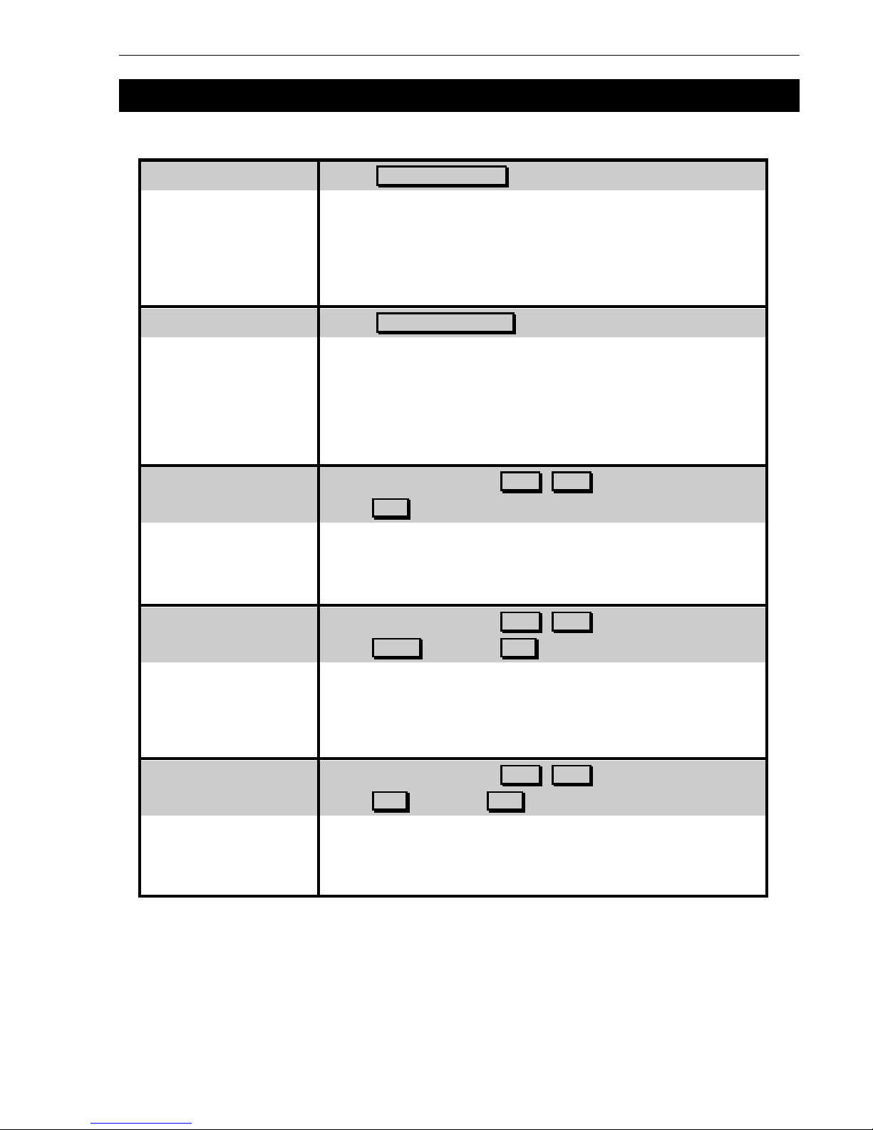
Emergency Operation
1 EMERGENCY OPERATION
Press: EXT BELL ISOLATE
•
EXT BELL ISOLATE LED will light
•
The external bells & panel buzzer will stop
•
A subsequent alarm will restart the panel buzzer but not the bells
•
The bell isolate can be toggled by pressing the button a second time
Press: WARN SYS ISOLATE
•
WARN SYS ISOLATE LED will light
•
The warning system will stop
•
A subsequent alarm will restart the panel uzzer but not the warning
system
•
The warning system isolate can by toggled by pressing the button a
second time
Select the Alarm using the PREV , NEXT buttons
Press: ACK to acknowledge
•
This will individually acknowledge alarms
•
Once all alarms are acknowledged the alarm LED will go steady
Select the Alarm using the PREV , NEXT buttons
Press: RESET then press ACK to confirm the resetting
•
This will individually acknowledge and reset alarms
•
Resets zone in alarm and clears all alarm inputs in the zone
•
If alarm is still present, the zone(s) will either stay in alarm or re-
alarm again after about 15 seconds
Select the Alarm using the PREV , NEXT buttons
Press: ISOL then press ACK to confirm the isolation
•
Isolates the point or zone
IN ALARM AND CLEARS IT’S ALARM OUTPUTS
•
Isolating a zone automatically acknowledges and isolates all points
in the zone
AFP-2800/2802 Manual – P/N DOC-01-011 7
Isolate Bells
Isolate Warning System
Acknowledging an Alarm
Resetting an Alarm
Isolate an Alarm
Page 8

Placing Into Operation
2 PLACING INTO OPERATION CHECKLIST
2.1
PRE POWER-UP CHECKS
System general appearance good
Cabinet colour and condition good
Cabinet keyed 003
All circuit boards firmly fastened
Manual call point fitted & functional
Viewing window clear and firmly secured
Cable entries adequately sealed
240 VAC cabling correctly terminated
All earthing secured
Power supply securely mounted
Power supply correctly wired
All ribbon cables firmly secured
All other components securely inserted
LCM boards correctly addressed and all analogue loops have been tested as per section 9.6.4.2
AFP-2800/2802 manufacturing label affixed
You are now ready to power up the AFP-2800/2802 Fire Indicator Panel.
Note: When re-booting the panel, power off for at least 10 seconds or LCM modules might not operate correctly.
2.2
POWER UP CHECKLIST
Ensure batteries are disconnected.
Turn mains switch To "ON"
After a few seconds, some power-up information should be displayed on the LCD screen, which will then
clear and display the alarm screen.
UNDER NORMAL CONDITIONS THE “NO ALARMS” MESSAGE WILL BE DISPLAYED.
THE INDICATOR LED’S ON THE REAR OF THE CPU BOARD WILL FLASH ON AND OFF.
The MAINS ON and FIRE FIGHTER lamps will be lit.
Connect the batteries.
Caution!! Incorrect polarity of batteries may cause permanent and serious damage to the system.
CHECK FOR SYSTEM FAULTS BY PRESSING, “SERVICE MENU”, “LIST”, “FAULTS”. IF THERE ARE ANY FAULTS, EITHER RECTIFY
or note in fault log on following page
Y
OU ARE NOW READY TO COMMENCE USING THE
AFP-2800/2802
FIRE PANEL
.
AFP-2800/2802 Manual – P/N DOC-01-011
8
Page 9

Placing Into Operation
2.3
FAULT RECORD
FAULT CORRECTION DATE
TESTS SATISFACTORILY COMPLETED.
TESTED BY
SIGNATURE
DATE OF TEST
If all faults have been rectified and all tests are completed satisfactorily, the AFP-2800/2802 is now ready for
operation.
AFP-2800/2802 Manual – P/N DOC-01-011 9
Page 10
System Description
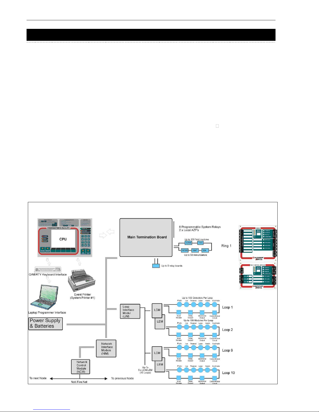
3 SYSTEM DESCRIPTION
The AFP-2800/2802 is a microprocessor based distributed Fire Detection/Alarm System. The panel comprises
multiple microprocessors for sharing the processing load both within the panel and in the field modules using
proprietary communications protocols
, THUS THE TERM “DISTRIBUTED SYSTEM”
.
The main panel communicates with the intelligent field devices via the RS485 communications ring. Each field
device can have multiple inputs and outputs. These inputs and outputs can include (but are not limited to) smoke
or heat detector circuits, bells and air conditioning controls.
The RS485 communications ring can support up to 100 distributed field modules and up to 50 panel annunciators
and 32 LCD80 units in terminal mode. The number of LCD-80s and modules on the ring will affect panel
performance and should be considered when designing the system.
In addition to the distributed conventional communication ring, the panel can support up to 10 loops of Analog
addressable points using various protocols including the proprietary Notifier FlashScan protocol. Each loop can
support 159 detectors and 159 modules.
In its maximum configuration, the AFP-2800 can support more than 802 Conventional Detection Circuits, more
than 400 Programmable Relay Outputs and 3,180 Analog addressable points. AFP-2802 supports a maximum of
396 Analog addressable points.
All of this data is stored in a large database and text based scripts are continuously processed to implement the
logic of input and output functions similar to a programmable logic controller (PLC).
THE SYSTEM’S CONFIGURATION DATA AND EVENT HISTORY IS STORED IN NON-VOLATILE “FLASH” MEMORY, WHICH DOES NOT RELY ON
battery power for its backup. The operating system is also stored in flash memory so there is no need for EPROM
changes to upgrade the firmware.
Note: Loops 3 to 10
are only available on
AFP-2800
AFP-2800/2802 Manual – P/N DOC-01-011
10
Page 11

Specifications & Approvals
4 SPECIFICATIONS & APPROVALS
4.1 G
ENERAL SPECIFICATIONS
(
SUBJECT TO CHANGE WIT HOUT NOTICE
):
Cabinet Zinc Sealed Steel
Powder Coated
Hinged Inner Door
Hinged Outer Door
Primary Microprocessor MC68EC000
Memory Type Non-volatile 16Mbit Flash; 1 Mbyte SRAM
Liquid Crystal Display LED Backlit 1/4 VGA graphical
Environmental Dry cold/heat:
-10 °C to +55 °C
Damp heat: +40 °C @ 93% Relative Humidity.
IP Rating IP 30
4.2
APPROVALS INFORMATION
Manufacturer: Notifier Fire Systems
9 Columbia Way
Norwest Business Park
NSW 2153 Australia
Phone: +61-2-9899-4155
Fax: +61-2-9899-4156
Product Name: Notifier Inertia AFP-2800
Approved to: AS4428.1 1998
Approval Report #: XF1769/R2 - Scientific Services Laboratory
ActivFire Listing No: AFP-1459
Approved to: NZS 4512:2003
Approval Report #: 05-527699.00 - Opus International Consultants Limited, Central Laboratories
Panel Serial #: ________________________
Date of Manufacture: ________________________
EMC WARNING:
This equipment may radiate radio frequency energy. It may also be affected by radio frequency energy and, if
NOT INSTALLED AND OPERATED IN ACCORDANCE WITH THE MANUFACTURER’S INSTRUCTIONS, MAY CAUSE INTERFERENCE TO
radio communications. It has been tested and found to comply with the Class A radiated and conducted EMI
requirements of AS/NZS CISPR 22:2009 (including Amendments 1 & 2) as well as the EMI susceptibility
requirements of Clause C3.5 in AS4428.0:1997.
Radio communication devices should not be used in the vicinity of fire panels or associated ancillary devices
and systems.
This is a Class A product. In a domestic environment this product may cause radio interference in which case
the user may be required to take adequate measures.
AFP-2800/2802 Manual – P/N DOC-01-011 11
Page 12

Specifications & Approvals
4.3
ELECTRICAL SPECIFICATIONS
Note: All functions and specifications described in this Operators Manual are subject to change without notice.
44..33..1
1
P
P
OOWWEER
R
S
S
UUPPPPLLY
Y
Parameter PS243 PS249 NPS-2 NPS-5 NPS-11
(3Amp) (9Amp) (2.6amp) (5.5amp) (11.7amp)
Input Voltage 240V AC +/- 240V AC +/- 110 or 240 Universal Universal
10% 10% (SW select)
Input Range 216V AC to 216 V AC to 85-132/170- 85-264VAC 88-264VAC
254V AC 254V AC 264VAC Auto Ranging Auto Ranging
(SW select)
Output Voltage 24V DC nom. 24V DC nom. 24V DC nom. 24V DC nom. 24V DC nom.
27.6V DC no 27.6V DC no 27.3V DC no 27.3V DC no 27.3V DC no
load load load load load
26.5 V DC full 26.5V DC full 27.3V DC full 27.3V DC full 27.3V DC full
load load load load load
Adjustable 12V DC to 30V 12V DC to 30V +/-10% +/-10% 26V to 32V
Range DC DC
Rated Current 3.0A @ 26.5V 9.0A @ 26.5V 2.6A @ 27V DC 5.5A @ 27V DC 11.7 @ 27V DC
Of Power Supply DC DC
Overload 7.4A @ Short 20A @ Short 105% to 150% 105% to 150% 105% to 135%
Current Device Circuit Circuit of rated power – of rated power – of rated power –
auto recovery auto recovery auto recovery
after fault after fault after fault
removal removal removal
Secondary 5A 15A N/A N/A N/A
Transformer
Fuse
Max Ripple 150mV p-p 150mV p-p 120mV p-p 150mV p-p 200mV p-p
Load Regulation 2% 2% ± 0.5% ± 0.5% ± 0.5%
Line Regulation 2% 2% ± 0.5% ± 0.5% ± 0.2%
Efficiency >80% >80% 82% 84% 88%
Battery Test Internal: 15 Internal: 15 External Load External Load External Load
ohms ohms
Battery Test 10A 15A N/A N/A N/A
Relay Contact
Rating
Indicators Mains On, Mains On, Mains On, Mains On, Mains On,
Output On Output On Charger Fault, Charger Fault, Charger Fault,
Battery Fault, Battery Fault, Battery Fault,
Battery test, Battery test, Battery test,
Batt test inhibit Batt test inhibit Batt test inhibit
Status Indicators By External By External Onboard LED or Onboard LED or Onboard LED or
Interface or FIP Interface or FIP External External External
Interface or FIP Interface or FIP Interface or FIP
Environmental -10°C to +55°C -10°C to +55°C -10°C to +55°C -10°C to +55°C -10°C to +55°C
Dry heat Dry heat Dry heat Dry heat Dry heat
+ 40°C @ 93% + 40°C @ 93% + 40°C @ 93% + 40°C @ 93% + 40°C @ 93%
RH RH RH RH RH
WARNING: Severe damage may occur if the batteries are connected incorrectly.
Note: When annunciators or field modules are powered from external power supplies, use a separate conductor to
connect the main power supply common terminal (-0V) to the remote power supplies common terminal (-0V).
AFP-2800/2802 Manual – P/N DOC-01-011 12
Page 13

Specifications & Approvals
44..33..22
T
T
EERRMMIINNAATTIIOON
N
BBOOAARRDD
((FFIIMM))
Supply Input 22 to 28V dc – fused at 9A (self-resetting)
requirements 55mA max (without CPU board or field loops connected)
210mA max (with CPU board, without field loops connected)
Alarm Inputs Two conventional Alarm Zone inputs are provided, detecting open
circuit fault, alarm, and normal. Each input is monitored and requires a
4K7 (nom) EOL resistor.
Power Auxiliary Power Output 20-28V 1A max
Outputs 24V dc & 5V dc Power to Ring Expander Boards
CPU power supply – 5V DC± 5% 3A
Alarm 4 x 1A monitored outputs (Bell & 3 spares – 4k7 EOL resistor)
Outputs 4 x ELV 1A relay contact outputs (Common Alarm, Fault plus 2 spare)
Communicati EIA485 on dual ports
ons Link 24Vdc (nom) 2A (max)
Note: Up to 100 field modules may be installed. Additional auxiliary
power supply(s) may be required, depending on the number of field
modules installed.
Indications LED indications of relay outputs, fuses, ring power and ground fault
44..33..33
P
P
AANNEEL
L
E
E
XXPPAANNSSIIOON
N
R
R
EELLAAYYSS
Panel Expansion Relays (XR) Up to 64 x 30Vdc @ 1A non-monitored relay
IFS-803 and IFS-717 contact outputs via 8 x IFS-803/IFS-717 relay
boards
44..33..44
LLCCM
M
/
/
LLEEM
M
A
A
DDDDRREESSSSAABBLLE
E
L
L
OOOOP
P
C
C
OONNTTRROOLLLLEER
R
M
M
OODDUULLEESS
Minimum Nominal Maximum
Operating voltage (V dc) 20.6 24 29
Loop communications voltage
15
24 32
Loop current limit (mA) 340 400 430
LCM/LEM Pair (Q Current) 140 200
Communications Link EIA485 on dual ports
LED Indications Green – Heart beat / Onboard 5Vdc supply OK
Amber – Ground fault / faulty card detected
44..33..55
NNCCM
M
N
N
EETTWWOORRK
K
CCOONNTTRROOLL
MMOODDUULLEE
NCM-W Supports twisted-pair wire medium, data is regenerated at
each node. 312.5K baud transmission rate.
NCM-F Supports fibre-optic medium (62.5/125 or 50/125
micrometres – multimode). Single mode available. 312.5K
baud transmission rate. Data is regenerated at each node.
HS-NCM High-speed data communications (12 Mb wire, 100 Mb
MF/SF fibre). Multi-mode fibre optic (MF), single-mode fibre
optic (SF),wire (W), or a combination of W/MF/SF
communications path.
AFP-2800/2802 Manual – P/N DOC-01-011 13
Page 14

Specifications & Approvals
44..33..66
F
F
AAN
N
CCOONNTTRROOLL
MMOODDUULLEE
Supply Input IFS700: 20 to 28Vdc
55mA max (no relays energised)
130mA max (all inputs and relays energised)
IFS710: 15 to 28Vdc
55mA max (no relays energised)
130mA max (all inputs and relays energised)
Inputs 3 x Opto Isolated 4k7 EOL
Outputs 3 x ELV 1A relay contact outputs (Max 30 Vdc or 24 Vac)
Communications Link EIA485 on dual ports
Indications LED indications on: Inputs,
Outputs
RX/TX
Power
Fault
44..33..77
AAZZM
M
8
8
MMOODDUULLEE
Supply Input IFS701: 20 to 28V DC
90mA max (no relays energised)
155mA max (all relays energised)
IFS711: 15 to 28V DC
80mA max (no relays energised)
125mA max (all relays energised)
238mA max (all AZF & relays energised)
43mA max (no relays energised, all AZF disabled)
Inputs 8 conventional alarm inputs
Monitoring – Open Circuit, Alarm, Fault
Outputs 4 x ELV 1A relay contact outputs (Max 30 VDC or 24 VAC)
Communications Link EIA485 on dual ports
Indications LED indications on: Outputs, RX/TX, Power, Fault
44..33..88
AACCMM--1166AAT
T
A
A
NNNNUUNNCCIIAATTOORR
Supply Input 20V to 28Vdc
40mA standby
180mA alarm
(ALL LED’S
on)
Communications Link EIA485 multi-dropped
44..33..99
AACCMM--3322A
A
A
A
NNNNUUNNCCIIAATTOORR
Supply Input 20V to 28Vdc
40mA standby
180mA a
LARM (ALL LED’S
on)
Communications Link EIA485 multi-dropped
AFP-2800/2802 Manual – P/N DOC-01-011
14
Page 15

Specifications & Approvals
44..33..1100 SSCCSS--8
8
A
A
NNNNUUNNCCIIAATTOORR
Supply Input 20V to 28Vdc
33mA standby
20mA max current per LED when LED ON
Communications Link EIA485 multi-dropped
44..33..1111 LLDDMM--RR332
2
A
A
NNNNUUNNCCIIAATTOORR
Supply Input 20V to 28Vdc
40mA Standby
200mA Alarm (32 relays energised)
Communications Link EIA485 multi-dropped
Relay contacts max 1A @ 30Vdc
44..33..1122 LLCCDD--880
0
D
D
IISSPPLLAAY
Y
IINNTTEERRFFAACCEE
Supply Input 20V to 28Vdc
100mA Standby
100mA Alarm
Communications Link EIA485 multi-dropped
AFP-2800/2802 Manual – P/N DOC-01-011 15
Page 16

Compatible Devices
5 COMPATIBLE DEVICES
5.1
ADDRESSABLE DEVICES
MAKE
MODEL
TYPE
MODEL NUMBER(S)
ANALOG ADDRESSABLE DETECTORS
Notifier
Thermal
Fixed Temp
FST-751, FST-851, FST-851H, FST-851WP,
FDX-851
Notifier
Thermal
Rate Of Rise
FDX-751, FST-751R, FST-851R, FST-851R-WP,
FDX-851R
Notifier
Smoke
Photo-Optical
FSP-751, FSP-851, SDX-851
Notifier
Smoke
Ionisation
FSI-751, FSI-851
Notifier
Smoke
VIEW
LPX-751L, FSL-751
Notifier
Smoke
Duct
FSD-751P, DNR, DNRW
Notifier
Combination
Acclimate
FAPT-751, FAPT-851
Notifier
Combination
HARSH
FSH-751
Notifier
Smoke
Beam
FSB-200, FSB-200s
Notifier
Combination
CO, Photo, Heat, IR
FSC-851, SDX-751CTEM
ANALOG ADDRESSABLE MODULES
Notifier
Input Module
Conventional Zone Interface
FZM-1
Notifier
Input Module
Monitor
MMX-1, FMM-1
Notifier
Input Module
Mini Monitor
MMX-101, FMM-101
Notifier
Output Module
Relay
CMX-2, FRM-1
Notifier
Output Module
Control Output
CMX-2, FCM-1
Notifier
Input Module
5 x Mini Monitor
XP5-M
Notifier
Output Module
5 x Relay/Control Output
XP5-C
Notifier
Input Module
6 x Conventional Zone Interface
XP6-MA
Notifier
Input Module
10 x Mini Monitor
XP10-M
Notifier
Output Module
6 x Relay
XP6-R
Notifier
Output Module
6 x Control Output
XP6-C
Notifier
Input/Output Module 2 x Monitor, 2 x Relay
FDMR-1
Notifier
Input module
Manual Call Point
FSM-500K, WCP-5A
Notifier
Sounder/Strobe
Sounder and/or Strobes
DBS24AL, ABS32, ABSB32, AWB32, AWS32,
AWSB32
LOOP ISOLATORS
Notifier
Module
Loop Isolator
ISO-X, M700XE
Notifier
Detector Base
Loop Isolator
B524IEFT
5.2
CONVENTIONAL DETECTORS
MAKE
MODEL
TYPE
MODEL NUMBER(S)
System Sensor
Thermal
Type A
5451AUS, 51A51
System Sensor
Thermal
Type B
4451AUS, 51B51
System Sensor
Thermal
Type B Sealed
885WP-B
System Sensor
Thermal
Type C
51C51
System Sensor
Thermal
Fixed TEMP 63
o
5151AUS
System Sensor
Thermal
ROR 63o
5151RAUS
System Sensor
Thermal
Fixed TEMP 90o
5151HAUS
System Sensor
Thermal
ROR 90o
5151HRAUS
System Sensor
Smoke
Photo-Optical
2151AUS,2151BAUS
System Sensor
Smoke
Ionisation
1151AUS
System Sensor
Smoke
Beam
BEAM1224(S)
System Sensor
Smoke
Duct
DH-100LP, D2
Notifier
Input
Manual Call Point
M400KR
Hochiki
Thermal
Type A
DCD-A, DCC-A, DCA-B-60R Mk V
Hochiki
Thermal
Type B
DFJ-60B, DFE-60B, DFG-60BLKJ
Hochiki
Thermal
Type C
DCD-C, DCC-C, DCA-B-90R Mk I
Hochiki
Thermal
Type D
DFJ-90D, DFE-90D
Hochiki
Smoke
Ionisation
SIJ-ASN, SIH-AM
Hochiki
Smoke
Photo Optical
SLR-AS, SLK-A
AFP-2800/2802 Manual – P/N DOC-01-011 16
Page 17

Compatible Devices
5.3
COMPATIBLE BATTERIES
In general, any Sealed Lead Acid (SLA) battery, or Wet Lead Acid battery designed for stationary use is
compatible with the AFP2800/2802 Fire Indicator Panel. The use of Nickel Cadmium batteries is not
recommended.
Manufacturer Type Number Voltage Capacity (Ah) Qty Required
Olympic Batteries SLA CJ12-7
12
7
2
Olympic Batteries SLA CJ12-12
12
12
2
Olympic Batteries SLA CJ12-18
12
18
2
Olympic Batteries SLA CJ12-26
12
26
2
Olympic Batteries SLA CJ12-33
12
33
2
Olympic Batteries SLA CJ12-40
12
40
2
Olympic Batteries SLA CJ12-85
12
85
2
Olympic Batteries SLA CJ12-100
12
100
2
NOTES:
Automotive batteries must not be used. There is a risk of explosion if battery is replaced by an incorrect type.
Dispose of used batteries according to Manufacturer Instructions
The use of Nickel Cadmium batteries is not recommended.
The batteries could be seriously and permanently damaged if they are permitted to discharge below 20V DC
when placed in series.
The NPS series of power supplies will only charge the battery if the terminal voltage is above 12V when
measured across 2 batteries in series.
AFP-2800/2802 Manual – P/N DOC-01-011 17
Page 18

System Capacity And Expandability
6 SYSTEM CAPACITY AND EXPANDABILITY
6.1
BASE SYSTEM
Item Description Notes
Communications Ring RS485 communications ring to support
Up to 100 Field Modules
Up to 50 Annunciators
8 System Outputs 4 x Monitored Outputs. Fault output is normally
Bell Output energised using V5.00
3 Additional and above firmware.
programmable outputs
4 x Clean contact relays Max contact rating of all
General Alarm Output relays 1A @ 30Vdc.
General Fault Output
2 x programmable outputs
Power Supply 2.6 A power supply and battery A larger power supply
charger may be required if total
Fused 27.3Vdc outputs module load exceeds
2A. Power supplies up
to 11.7A are available.
2 LOCAL AZF’S
AZF 1
AZF 2
2 RS232 communication Laptop interface
ports System event printer
Remote terminal mode
Keyboard Interface PS2 QWERTY IBM PC keyboard
System Memory Approx. 4300 Named points
Approx. 4000 Control scripts
4000 History events
6.2
EXPANSION PCBS
Item Description Notes
Loop Interface Module Interface module to communicate with Each Analog
(LIM) up to 5 x pairs of Notifier LCM/LEM addressable loop
modules. I.e. total of 10 FlashScan supports up to 159
Analog addressable loops for AFP- detectors and 159
2800 and a total of 4 CLIP Analog addressable modules
addressable loops for the AFP-2802. using the Notifier
FlashScan protocol or
99 detectors and 99
modules using the CLIP
protocol.
Network Interface Interface module to communicate with AFP-2800 only.
Module (NIM) the Network Control Module (NCM) AFP-2802 does not
support Networking.
Panel Expansion Relays Relay card with 8 relays – contact Up to 8 IFS-803/IFS-717
(IFS803 or IFS-717) rating is 1A @ 24Vdc 8-way relay boards can
be added
AFP-2800/2802 Manual – P/N DOC-01-011
18
Page 19

System Capacity And Expandability
6.3
ANALOG ADDRESSABLE LOOPS
Item Description
Loop Control Module Loop Controller for Loops 1,3,5,7,9
(LCM/ELC)
Loop Expander Module Loop Controller for Loops 2,4,6,8,10
(LEM)
6.4 A
NNUNCIATORS
Item Description
ACM32 Annunciator 32 Red LED
ACM16AT Annunciator 16 x Pushbutton inputs
16 x Red LED
16 x Yellow LED
SCS-8 Annunciator 8 x 3 Position switches
8 x Red LED
8 x Yellow LED
8 x Green LED
1 x Fire Trip (A/C) Reset switch
1 x Fire Trip (A/C) Activated/Latched LED
SCS-8L Annunciator 24 x LED outputs & 25 digital inputs
LDM-32 Annunciator 32 x LED outputs (Open Collector)
LDM-R32 Annunciator 32 x Relay outputs rated to 1A @ 30Vdc
6.5
FIELD MODULES
Item Description
AZM-8 8 x AZF inputs (4k7 EOL resistor)
4 x Programmable Relay Outputs
Fan Controller (FAN-C) 3 x Inputs (Opto-isolated, not monitored)
3 x Programmable Relay outputs
The RS485 signal is
regenerated at each
field module.
Note: Please note that the FAN-C module has been discontinued and will not be supplied for new installations.
When annunciators or field modules are powered from external power supplies, use a separate conductor to
connect the main power supply common terminal (-0V) to the remote power supplies common terminal (-0V).
AFP-2800/2802 Manual – P/N DOC-01-011 19
Notes
Max 5 per AFP-2800
Max 1 per AFP-2802
Max 5 per AFP-2800
Max 1 per AFP-2802
LEM “PIGGYBACKS”
under the LCM.
Notes
A maximum of 50
annunciators can be
connected to the
communications ring.
Notes
A maximum of 100
field modules can be
connected to the
communications ring.
Larger/external power
supplies and separate
feeds are required for
systems with a large
number of modules or
long cable runs.
Page 20

System Capacity And Expandability
6.6
DISPLAY INTERFACES
Item Description Notes
LCD80 Terminal mode display interface (see A maximum of 32
LCD 80 manual) display interfaces can
be installed on the
communications ring.
Address 201 to 239
LCD80 Annunciator mode display interface (see A maximum of 32
LCD 80 manual) display interfaces can
be installed on the
communications ring.
Address 101 to 139
AFP-2800/2802 Manual – P/N DOC-01-011
20
Page 21

Panel Operation
7 PANEL OPERATION
7.1
FRONT PANEL DISPLAY
The AFP-2800/2802 is fitted with a LED backlit 1/4 VGA resolution graphical LCD screen allowing ease of use for
the operator by displaying multiple lines of information. The AFP-2800/2802
USES THE CONCEPT OF “HARD” AND “SOFT”
buttons.
A “HARD” BUTTON IS ONE WHICH IS LABELLED WITH A FIXED FUNCTION (E.G
. EXT BELL ISOLATE ).The functions of these
buttons do not change.
A “SOFT” BUTTON IS ONE OF THE FIVE BUTTONS ALONG THE BOTTOM OF THE LCD DISPLAY. THE FUNCTION OF THE BUTTON MAY
change depending on the screen being displayed at the time. To indicate the button function, its label is changed
by software, and displayed along the bottom line of the LCD as a pictorial representation of a button. Not all
buttons are shown on a screen, and the unlabelled buttons will have no effect if pressed.
Rather than having a cluttered front keypad fascia with letters numbers and function keys, the AFP-2800/2802
accepts a standard PC101 style keyboard plugged directly into the CPU to allow full QWERTY function
accessibility for programming and diagnostic test.
The LCD display is used to display information about the status of the system, field devices, and programming
MENUS. THE LAYOUT OF THE FRONT KEYPAD PROVIDES A “FIRE
-fighter's F
ACILITY” IN ACCORDANCE WITH AS4428. THE PURPOSE
of this facility is to provide a uniform display for all fire alarm panels to assist Fire fighters during a response. The
thick red border signifies the fire-fighters area and provides alarm-based functions for the fire fighter.
The mode select buttons (bottom right) will toggle the system in between fire-fighters mode and the service menu
where routine service and diagnostic tests can be performed. If there are any active and unacknowledged alarms
on the system, the system will switch to and remain in fire-fighters mode until all alarms are acknowledged or
reset.
77..11..11
S
S
EELLEECCTTIINNG
G
S
S
CCRREEEEN
N
I
I
TTEEMMSS
Selecting a screen item may be done in two ways
1
. On a screen where the functions are numbered (e.g. Service Menu screen), pressing the number in front of
the appropriate item will immediately select that item.
2
. On a screen with UP/DOWN facility, pressing the UP or DOWN (or PREV / NEXT ) button will move the
highlighted cursor up or down the list. When the SELECT button is pressed, the highlighted item will then be
selected.
77..11..22
S
S
CCRROOLLLLIINNG
G
T
T
HHRROOUUGGH
H
L
L
IISSTTSS
When a list of points is displayed on the screen, you can scroll through the list by pressing the UP or DOWN (or
PREV / NEXT ) button. This will move the highlighted cursor up or down the list. If the button is held down, the
cursor will scroll more quickly and if it is held down for several seconds, the list will scroll page by page, enabling
rapid access to item near the end of a long list.
When accessing the history List (which is a first-in, first-out list), simply press Page Up at the top of the list to be
immediately taken to the last page of the list.
AFP-2800/2802 Manual – P/N DOC-01-011 21
Page 22

Panel Operation
77..11..3
3
E
E
NNTTEERRIINNG
G
I
I
NNFFOORRMMAATTIIOON
N
On screens where character information needs to be entered, such as point labels, this must be done using an
external QWERTY style keyboard plugged into the PS2 keyboard plug on the rear of the CPU panel. On screens
(e.g. menus, change time/date) that require only numbers to be entered, the ten digit numeric keypad can be
used.
77..11..4
4
S
S
YYSSTTEEM
M
C
C
OOUUNNTTEERRS
S
On the top right hand side of all screens are the system counters showing the total number of
alarms, faults, isolates and non-alarm (active) events on the system at any time. If a device is
both isolated and in fault it will increment both counters. For more information as to which points
are isolated, refer to the list menus.
77..11..5
5
P
P
OOIINNT
T
F
F
OORRMMAATTS
S
There are three different types of point in the AFP-2800/2802 system – real (or physical) points, virtual (software
generated) points and network points.
All points on the distributed ring and the Analog addressable loops are real points. Distributed points on field
modules are controlled and referred
TO IN “R.M.IO” FORMAT. i.e.: Ring.Module.I/O – where I/O can consist of input,
output or AZF. Analog addressable
POINTS ON THE ADDRESSABLE LOOPS ARE CONTROLLED AND REFERRED TO IN “LOOP, I/O
FORMAT”
i.e. Loop I/O where I/O can consist of module or detector number.
Virtual points are referred to as VPx where x can range from 1 to 1000. Virtual points are actually the output from
a script equation and are discussed later in this manual (refer to page 96).
Network points are referred to as NPx where x can range from 1 to 1000. Each network node can have up to 1000
Netpoints. Network points are real or virtual points mapped at any network node that is required to interact with
other network nodes (refer to page 93).
Examples are as follows:
Point to be referred to Syntax
Ring 1, Module 1, Output 1 1.1.O1
Ring 1, Module 20, AZF input 1 (AZM-8) 1.20.Z1
Ring 1, Module 30, input 1 (FAN-C) 1.30.I1
Ring 1, Annunciator 1 (module 101), Output 1 (led #1) 1.101.O1
Ring 1, Annunciator 50 (module 150), Input 1 (button #1) 1.150.I1
Loop 1 Detector 1 L1D1
Loop 1 Module 1 L1M1
Expansion relay 1 XR1
Virtual point 1 VP1
Network point 1 on Node 1 N1.NP1
AFP-2800/2802 Manual – P/N DOC-01-011 22
A = 2
F = 5
I = 10
N = 5
Page 23

Panel Operation
System points will be displayed and can be referred to as follows:
Description Syntax Comments
ON BOARD AZF’S
2 AZF’S ON TERMINATION BOARD
AZF #1 0.1.Z1 Ring 0 Module 1, zone 1
AZF #2 0.1.Z2 Ring 0 Module 1, zone 2
On Board Relays 8 Relays on termination Board
Relay 1 to 8 on FIM 0.4.O1 to 0.4.O8 Ring 0 Module 4, output 1
Ring 0 Module 4, output 8
Distributed Field Modules Up to 100 modules
AZF 1.1.Z1 8 AZF points per AZM8module
Din 1.1.I1 3 Din Per Fan Control Module
Dout 1.1.O1 4 Dout Per AZM-8
3 Dout Per Fan Control Module
Annunciator Up to 50 Annunciators
Inputs 1.101.I1 16 Din per 16AT, 24 Din Per SCS-8
Outputs 1.101.O1 32 Dout Per 16AT, 24 Dout Per SCS-8, 32
Dout Per ACM32A
Analog Addressable Devices Up to 10 Loops
Detectors L1D1 159 Detectors Per Loop
Modules L1M1 159 Modules Per Loop
Virtual Points VPn n can range up to 1000
Network Points NPn n can range up to 1000
Expansion Relays XRn n can range up to 64
System Parameters
Common Alarm CA
Common Fault CF
Common Isolate CI
Battery Fault BF
Charger Fault CL
Mains On MO
Ext. Bell Isolated BI
Warning System Isolated WI
AFP-2800/2802 Manual – P/N DOC-01-011 23
Page 24

Panel Operation
77..11..66
A
A
NNNNUUNNCCIIAATTOOR
R
A
A
DDDDRREESSSSIINNGG
The AFP-2800/2802 can support up to 50 annunciator devices on the distributed ring. There are 4 types of
annunciators that can be used.
Type Description Suggested Use
ACM32A 32 Red LED Mimic panel
ACM16AT 16 Pushbuttons Output control for flow switches and
16 Red LED test solenoids.
16 Amber LED Isolate control for isolating zones or
points.
SCS-8 8 x 3 position switches Fan Control for up to 8 fans.
8 Red LED
8 Amber LED
8 Green LED
1 x pushbutton and Red LED for FTR
LDM-32 32 LED outputs Site specific mimic panel
LDM-R32 32 x 1 Amp relay outputs EWIS interface
As the annunciators co-exist on the same RS485 ring as the distributed field modules, the annunciator addresses
have 100 added to them. I.e. an annunciator set to address 1 is recognised as module address 101. Annunciators
are simply treated as digital inputs and digital outputs to the system. Each button press or switch position is
considered as an input, each LED is considered as an output.
Example 1: If an ACM32A annunciator is installed and addressed as #1. The last red LED on it would be referred
TO AS 1.101.O32 USING THE “RING.MODULE.I/O” FORMAT.
Example 2: If an ACM16AT was installed and addressed as #2. The first pushbutton on it would be referred to as
1.102.I1 USING THE “RING.MODULE.I/O” FORMAT
.
Example 3: If an SCS-
8 WAS INSTALLED AND ADDRESSED AS #3. THE FIRST SWITCH IN THE “UP” POSITION WOULD BE REFERRED
TO AS 1.103.I1 USING THE “RING.MODULE.I/O” FORMAT
.
Example 4: If an LDM-R32 annunciator is installed and addressed as #4. The last relay on it would be referred to
AS 1.104.O32 USING THE “RING.MODULE.I/O” FORMAT
.
Note: Please refer to Section 9.11 for more information on annunciator addressing and settings.
AFP-2800/2802 Manual – P/N DOC-01-011
24
Page 25
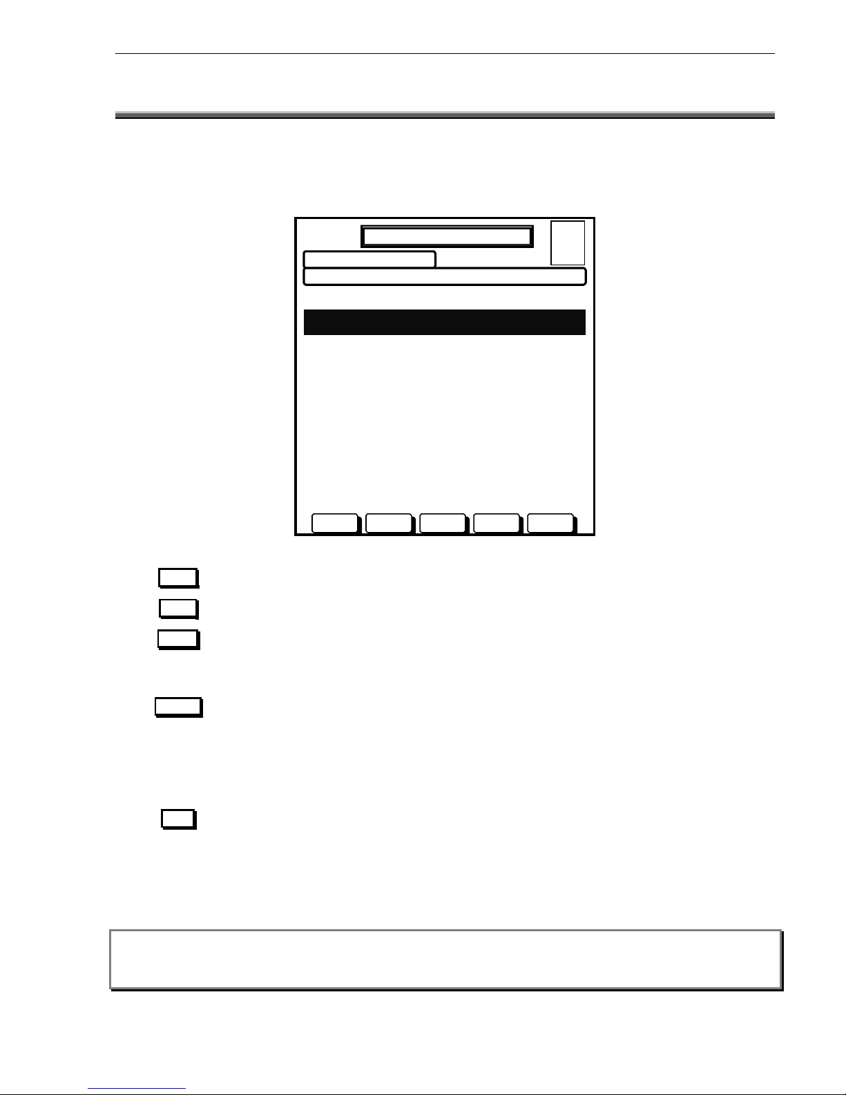
Will scroll the cursor up the list to the previous item.
Will scroll the cursor down the list to the next item.
Will cause the alarm to be marked as acknowledged.
Will perform a point reset function on the currently highlighted alarm. As per AS4428,
you will be requested to press ACKN to confirm the reset. Any other button will abort
the reset. The point is automatically acknowledged by this action. Once an alarm is
reset, it will be removed from the screen, however if the alarm condition is still present,
it will re-alarm after a 15 second time out.
Will perform a point isolate function on the currently highlighted alarm. As per AS4428,
you will be requested to press ACKN to confirm the isolate. Any other button will abort
the isolate. The point is automatically acknowledged by this action. Once an alarm is
isolated, it will be remain on the screen marked as an isolated alarm and must be reset
to clear from the alarm screen. Once an alarm is isolated, to deisolate the alarm you
must go through the service menu, isol/deisol function.
Note:
IF “GROUP ZONES” FOR FIRE
Fighters display is selected for AS4428, the zone displayed in fire fighters mode may
be a collection of several points on the system. Resetting or isolating a zone will result in all the underlying
points being isolated or reset. To view, isolate or reset individual alarm points you must go to the Service
Menu and list alarms, after acknowledging all active alarms.
AFP-2800/2802 Manual – P/N DOC-01-011 25
Panel Operation
7.2
FIREFIGHTERS MODE
Only the one
SCREEN IS AVAILABLE IN THIS MODE. THE “SOFT” BUTTONS CONTROL THE FUNCTIONS AVAILABLE
.
This mode is automatically entered when any unacknowledged alarm is present, and until all alarms are
acknowledged or cleared, no other screen can be selected. The top right corner of the screen shows a quick
system status, giving the total alarms, faults, isolates and non-alarm events at that time.
The soft button functions for this screen operate as follows:
PREV
DAY MODE
20 JULY 2002 14:44:37
ZONE LABEL STATUS TIME
PENTHOUSE 20 July 10:12
ZONE 23 ALARM 1/2
STAIRWELL 20 July 10:07
ZONE 22 ACKD ALARM 2/2
PREV NEXT ACKN RESET ISOL
NOTIFIER INERTIA AFP2800 FIP
A = 2
F = 0
I = 0
N = 0
NEXT
ACKN
RESET
ISOL
Page 26

Panel Operation
7.3 SERVICE MENU MODE
77..33..11
1) List
1) Alarm
2) Fault
3) Isolated
4) Active
4) Dout
5) Prealarm
5) Din
6) List
6) Virtual
1) Zone
7) Analog
2) Azf
8) Range
3) Dout
9) Group
4) Din
0) Network
5) Virtual
6) Netpoint
7) Analog
8) Ring
7) History
8) Shadow
AFP-2800/2802 Manual – P/N DOC-01-011
26
S
S
EERRVVIICCE
E
M
M
EENNUU SSTTRRUUCCTTUURREE
Service Menu
2) Isolate
1) Isolated
2) Zone
3) Azf
1) Azf
2) Alarm
3) Fault
4) Dout
5) Battery
6) Walk
1) Zone
2) Azf
3) Dout
4) Din
5) Virtual
6) Netpoint
7) Analog
8) Change
9) Module
3) Config
4) Analog
5) Test
1) List
2) Status
3) Change
4) Remove
5) Loop
6) Analog
7) Fault
Page 27

Service Menu
7) Print
8) Diag
9) Network
0) Log off
1) Alarm List
1) Stats
1) Network
2) Fault List
2) Dbase
2) Status
3) Isolate List
3) Flash
3) Node
4) Active List
4) Relay
4) Receive
5) History
5) Xrelay
5) Options
6) Script
6) Led
7) Analog
7) Module
8) Ring Modules
8) Local
9) History
Restart System
Erase Sectors
Deisol All Isol
Note: The networking menu is only displayed on the AFP-2800 FIP. AFP-2802 does not support networking.
AFP-2800/2802 Manual – P/N DOC-01-011 27
Panel Operation
6) Global
1) System
2) Time
3) Day-Night
4) Passwords
5) Site
6) Print
Page 28

Panel Operation
77..33..22
S
S
EERRVVIICCE
E
M
M
EENNUU
This is the base level of service menu mode.
Screen functions such as the selection of a menu item may be selected in two ways.
1
. By using the soft UP or DOWN buttons to scroll to the required item, then pressing SELECT or
2
. By selecting the menu item number on the keypad.
The top right corner of the screen shows a quick system status, giving the total number of alarms, faults, isolates
and non-alarm (supervisory) events at any given time.
Pressing the SERVICE MENU button at any time will return you to this main menu screen unless there are
unacknowledged alarms present in the FireFighters screen.
Actions:
DAY MODE
•
Use UP and DOWN buttons to scroll through
options.
•
Use SELECT to select the currently highlighted
option.
3) CONFIG CONFIGURE MODULES/POINTS
•
Alternatively press 1 through to 9 (use 0 to
select LOG-OFF).
9) NETWORK CONFIGURE NETWORK PARAMETERS
USE BUTTONS/NUMBERS TO SELECT A FUNCTION
UP DOWN SELECT
AFP-2800/2802 Manual – P/N DOC-01-011
28
6) GLOBAL CONFIGURE SYSTEM PARAMETERS
1) LIST LIST POINT INFORMATION
2) ISOLATE ISOLATE/DEISOLATE POINTS
4) ANALOG ADDRESSABLE LOOP FUNCTIONS
0) LOG-OFF RESET PASSWORD TIMER
8) DIAG VARIOUS DIAGNOSTIC TESTS
20 JUL 2002 14:44:37
5) TEST TEST FUNCTIONS
7) PRINT VARIOUS PRINTING UTILITIES
SERVICE MENU
A = 0
F = 0
I = 0
N = 0
Page 29

Panel Operation
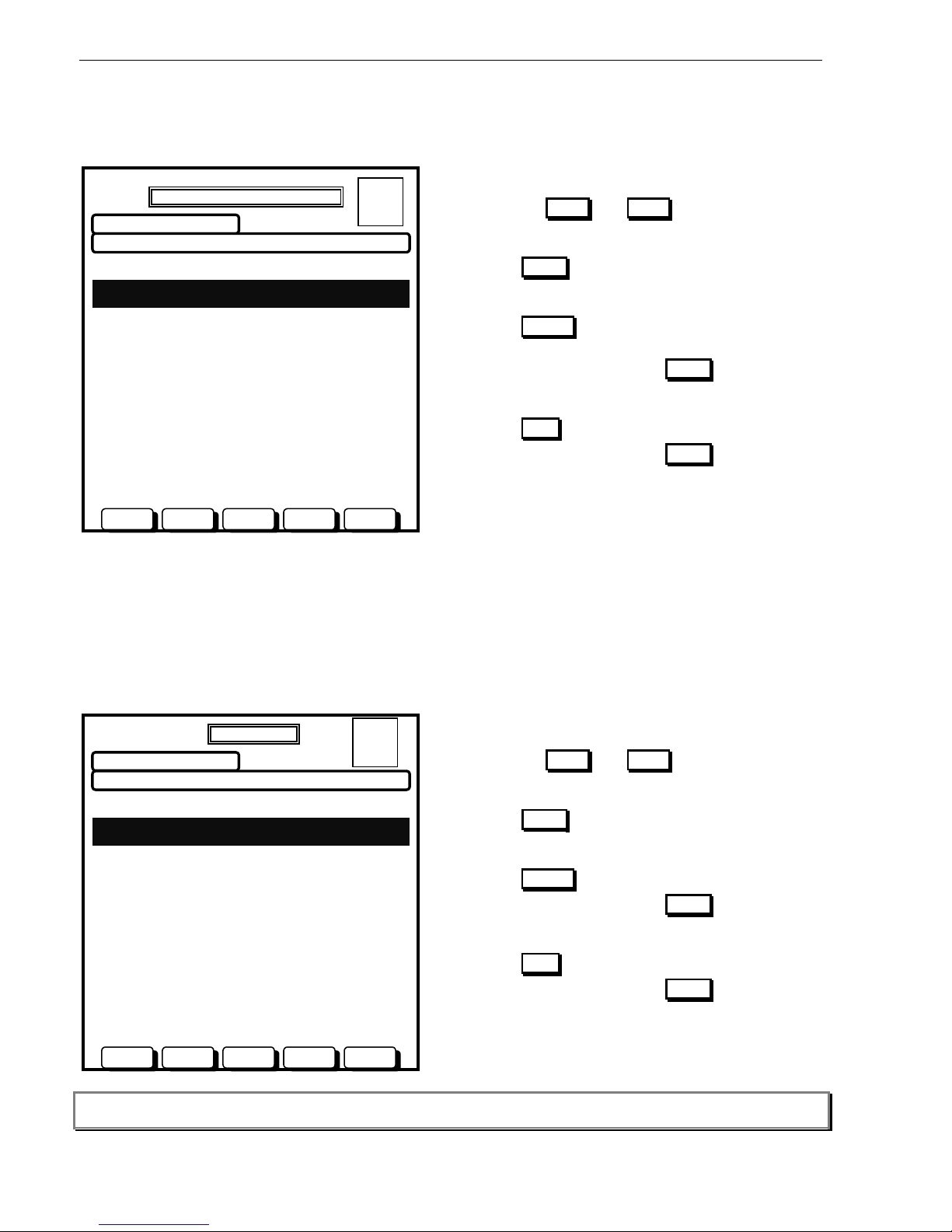
77..33..33
S
S
EERRVVIICCE
E
M
M
EENNU
U
–
–
L
L
IISSTT
These menus allow access to various information lists. List Menu 1 is shown first. Use the PREV and NEXT
buttons to scroll through the options then use SELECT to select the currently highlighted option or use the
numeric keypad. Item (6) on List Menu 1 (LIST) will move you to List Menu 2. The MENU button will return you
to the Service Menu. The available lists are:
DAY MODE
20 JULY 2002 14:44:37
1) ALARM DISPLAY ALARMS
2) FAULT DISPLAY FAULTS
3) ISOLATED DISPLAY ISOLATED POINTS
4) ACTIVE DISPLAY ACTIVE/NON-ALARM
5) PREALARM DISPLAY PREALARMS
6) LIST DISPLAY 2800 POINTS
7) HISTORY DISPLAY SYSTEM HISTORY
8) SHADOW DISPLAY SHADOW HISTORY
USE BUTTONS/NUMBERS TO SELECT A FUNCTION
SELECT MENU
Explanation
Displays all current alarms on the system in chronological order and allows you to acknowledge reset and isolate
alarmed points using the soft buttons
.
Displays all current faults on the system in chronological order, and allows you to acknowledge, reset and isolate
fault points using the soft buttons
Displays all currently isolated points on the system and provides a soft button for de-isolation.
Displays all active Non-Alarm events on the system in chronological order and allows you to acknowledge, reset
and isolate points using the soft buttons
.
Displays all active Pre-Alarm events on the system in chronological order and allows you to acknowledge, reset
and isolate points using the soft buttons
.
Moves you to List Menu 2 with the menu items listed below
Displays the systems history event buffer in chronological order.
Displays the systems shadow history event buffer in chronological order.
Display zones as per AS4428. Allows editing of displayed zone names for Fire-fighters display purposes.
DISPLAYS ALL SYSTEM AZF’S AND SHOWS CURRENT STATUS. SOFT BUTTONS PROVIDE ABILITY TO TEST AND CHANGE A POINTS
programming
.
Displays all system Digital Outputs (Relays & LEDs) and shows current status. Soft Buttons provide ability to
Test and Cha
NGE A POINT’S PROGRAMMING
.
Displays all system Digital Inputs and shows current status. Soft Buttons provide ability to Test and Change a
POINT’S PROGRAMMING
.
Displays all system Virtual Points. Soft Buttons provide ability to change a
POINT’S PROGRAMMING.
DISPLAYS ALL SYSTEM NETPOINTS. SOFT BUTTONS PROVIDE ABILITY TO CHANG E A POINT’S PROGRAMMING.
Displays Analog addressable loops 1-10 and detectors/modules with names for status viewing, editing and
testing
.
Displays the systems communications rings and mo dules found on each.
AFP-2800/2802 Manual – P/N DOC-01-011 29
UP DOWN
DAY MODE
20 JULY 2002 14:44:37
N = 0
1) ZONE DISPLAY ZONE GROUPS
2) AZF DISPLAY ALARM ZONES
3) DOUT DISPLAY DIGITAL OUTPUTS
4) DIN DISPLAY DIGITAL INPUTS
5) VIRTUAL DISPLAY VIRTUAL POINTS
6) NETPOINT DISPLAY NETWORK POINTS
7) ANALOG DISPLAY ADDRESSABLE POINTS
8) RING DISPLAY AVAILABLE RINGS
USE BUTTONS/NUMBERS TO SELECT A FUNCTION
UP DOWN
Menu Item
ALARM
FAULT
ISOLATED
ACTIVE
PREALARM
LIST
HISTORY
SHADOW
ZONE
AZF
DOUT
DIN
VIRTUAL
NETPOINT
ANALOG
RING
SELECT MENU
A = 0
F = 0
I = 0
A = 0
F = 0
I = 0
N = 0
LIST MENU 1
LIST MENU 2
Page 30
Panel Operation
7.3.3.1
SERVICE MENU – LIST – ALARM
This screen will display all individual alarm conditions active at the time. As new alarms (unacknowledged) force
the panel into Fire Fighters mode, this page can only be accessed once all alarms are acknowledged.
Actions:
•
Use the PREV and NEXT buttons to scroll
through the active Alarms.
•
Use ACKN to acknowledge currently highlighted
alarm.
•
Use RESET to reset the currently highlighted
alarm.
You will be asked to press ACKN to confirm, press
any other button to abort.
•
Use ISOL to isolate the currently selected alarm.
You will be asked to press ACKN to confirm, press
any other button to abort.
7.3.3.2
SERVICE MENU – LIST – FAULT
This list will display all system faults in chronological order. If faults are set as non-latching, they will self clear
from this list. If faults are set to latching, a reset action from this list is the only way to clear them. Once a fault is
isolated it remains in the fault list but does not operate the fault outputs. Faults on Analog points will also indicate
a fault code as shown in the example screen below (refer to section 9.5).
Actions:
•
Use the PREV and NEXT buttons to scroll
through the faults.
•
Use ACKN to acknowledge currently selected
fault.
•
Use RESET to reset the currently selected fault.
You will be asked to press ACKN to confirm, press
any other button to abort.
•
Use ISOL to isolate the currently selected fault.
You will be asked to press ACKN to confirm, press
any other button to abort.
Note: You can also use the arrow keys, the Page Up and Page Dn keys on an external keyboard for scrolling
functions.
AFP-2800/2802 Manual – P/N DOC-01-011 30
DAY MODE
20 JULY 2002 14:44:37
TIME TYPE STATUS NUMBER
20 JULY 14:01 SMOKE ACKD ALARM 1 OF 2
L1D1 PENTHOUSE
20 JULY 14:40 HEAT ACKD ALARM 2 OF 2
1.10.Z1 NORTH STAIRWELL
PREV NEXT ACKN RESET ISOL
A = 2
F = 0
I = 0
N = 0
INDIVIDUAL POINT ALARM LIST
DAY MODE
20 JULY 2002 14:44:37
TIME TYPE STATUS NUMBER
20 JULY 10:00 SMOKE FAULT (F01) 1 OF 2
L1D1 PENTHOUSE
20 JULY 12:15 HEAT ISOL FAULT 2 OF 2
1.10.Z1 STAIRWELL
PREV NEXT ACKN RESET ISOL
FAULT LIST
A = 0
F = 2
I = 1
N = 0
Page 31

Panel Operation
7.3.3.3
SERVICE MENU – LIST – ISOLATED
This will display any isolation conditions active at the time
.
Actions:
•
Use the PREV and NEXT buttons to scroll
through the isolated points.
•
Use DEISOL to De-Isolate the currently selected
isolated point.
•
Press MENU to return to the Service menu
Note: You can also use the arrow keys, the Page Up and Page Dn keys on an external keyboard for scrolling
functions.
7.3.3.4
SERVICE MENU – LIST – ACTIVE
This list will display all non-alarm points that are currently active. If points are set as latching, this is where they
will need to be manually reset. If points are non-latching, they will self-clear.
Actions:
•
Use the PREV and NEXT buttons to scroll
through the active Non-Alarm AZF.
•
Use ACKN to acknowledge currently highlighted
active non-alarm AZF.
•
Use RESET to reset the currently highlighted
active non-alarm AZF.
You will be asked to press ACKN to confirm, press
any other button to abort.
•
Use ISOL to isolate the currently highlighted active
Non-Alarm AZF.
You will be asked to press ACKN to confirm, press
any other button to abort.
Note: You can also use the arrow keys, the Page Up and Page Dn keys on an external keyboard for scrolling
functions.
AFP-2800/2802 Manual – P/N DOC-01-011 31
DAY MODE
20 JULY 2002 14:44:37
TIME TYPE STATUS NUMBER
20 JULY 10:00 SMOKE ISOL 1 OF 2
L1D1 PENTHOUSE
20 JULY 12:15 HEAT ISOL FAULT 2 OF 2
1.10.Z1 STAIRWELL
PREV NEXT DEISOL MENU
ISOLATE LIST
A = 0
F = 0
I = 2
N = 0
DAY MODE
20 JULY 2002 14:44:37
TIME TYPE STATUS NUMBER
20 JULY 10:00 SMOKE ACTIVE 1 OF 2
L1D1 PENTHOUSE
20 JULY 12:15 HEAT ISOL ACTIVE 2 OF 2
1.10.Z1 STAIRWELL
PREV NEXT ACKN RESET ISOL
ACTIVE LIST
A = 0
F = 0
I = 1
N = 2
Page 32

Panel Operation
7.3.3.5
SERVICE MENU – LIST – PRE ALARM
This list will display all current pre-alarms. A pre-alarm will sound the local panel buzzer however this function can
be disabled from the Global System options screen (refer to Section 7.3.7.1).
Actions:
•
Use the PREV and NEXT buttons to scroll
through the list.
•
Use ACKN to acknowledge currently selected
active pre-alarm point.
•
Use RESET to reset the currently selected pre-
alarm point.
You will be asked to press ACKN to confirm, press
any other button to abort.
•
Use ISOL to isolate the currently highlighted active
Pre-Alarm point.
You will be asked to press ACKN to confirm, press
any other button to abort.
Note: You can also use the arrow keys, the Page Up and Page Dn keys on an external keyboard for scrolling
functions.
AFP-2800/2802 Manual – P/N DOC-01-011 32
DAY MODE
20 JULY 2002 14:44:37
TIME TYPE STATUS NUMBER
20 JULY 10:00 SMOKE ACTIVE 1 OF 2
L1D1 PENTHOUSE
20 JULY 12:15 HEAT ISOL ACTIVE 2 OF 2
L1D2 STAIRWELL
PREV NEXT ACKN RESET ISOL
PREALARM LIST
A = 0
F = 0
I = 1
N = 2
Page 33

Panel Operation
7.3.3.6
SERVICE MENU – LIST – LIST – ZONE
This list will display the systems display zones and provide the ability to edit the zone name and view
membership. The zone names as listed will be exactly how they display on the Fire Fighters screen (up to 28
characters maximum). Editing the members of a zone must be performed from the edit points menu.
Actions:
DAY MODE
20 JULY 2002 14:44:37
USE UP/DOWN BUTTONS TO SELECT A ZONE:
ZONE1: LEVEL 1 COMMON AREAS
ZONE2: FIRE CONTROL ROOM
ZONE3: LEVEL 1 BATHROOM
ZONE4: LEVEL 1 BALLROOM
ZONE5: LEVEL 2 COMMON AREAS
ZONE6: LIFT MOTOR ROOM
ZONE7: UNNAMED POINT
ZONE8: UNNAMED POINT
ZONE9: UNNAMED POINT
ZONE10: UNNAMED POINT
ZONE11: UNNAMED POINT
ZONE12: UNNAMED POINT
ZONE13: UNNAMED POINT
ZONE14: UNNAMED POINT
ZONE15: UNNAMED POINT
ZONE16: UNNAMED POINT
UP
DOWN
CHANGE
Note: You can also use the arrow keys, the Page Up and Page Dn keys on an external keyboard for scrolling
functions.
7.3.3.6.1 SERVICE MENU
–
LIST – LIST – ZONE – CHANGE
On this screen you can edit a zones name by using the external QWERTY keyboard. Press enter when done.
Actions:
DAY MODE
20 JULY 2002 14:44:37
SELECTED POINT: ZONE 3
NAME: > LEVEL 1 BATHROOM
POINT TYPE >
AVF? (Y/N) > N
DEVICES IN ZONE
L1D1 L1D2 LID3 LID4 LID5 L1D6
Use TAB to move around.
INS, DEL to edit lines.
ENTER accept line and/or
Skip to next item.
ESC to leave without
change.
ESC BACKSP ENTER
AFP-2800/2802 Manual – P/N DOC-01-011
•
Use the CHANGE button to edit a zone name and
to view its membership.
•
Use the BACK button to return to the previous
screen.
BACK
•
Use the UP and DOWN buttons to scroll through
the zone list.
ZONE GROUPS LIST
A = 0
F = 0
I = 0
N = 0
•
Edit the zone name using the QWERTY keyboard.
Press ENTER when done.
•
To abandon changes press ESC
Note: Adding/deleting points in the zone is done by
editing the individual point configuration.
33
MODIFY POINT
A = 0
F = 0
I = 0
N = 0
OVERWRITE MODE
Page 34

Panel Operation
7.3.3.7
SERVICE MENU – LIST – LIST – ANALOG
This menu will list all Analog addressable loops (1 –10), you can then select detectors or modules, then read
status or change or test a point
.
Actions:
DAY MODE
20 JULY 2002 14:44:37
1)
LOOP 1
2)
LOOP 2
3)
LOOP 3
4)
LOOP 4
5)
LOOP 5
6)
LOOP 6
7)
LOOP 7
8)
LOOP 8
9)
LOOP 9
0)
LOOP 10
UP DOWN SELECT BACK
Once you have selected the loop you will be prompted to select detectors or modules as follows:
Actions:
•
Use the UP and DOWN buttons to select option.
•
Use the SELECT button to select the loop to list.
SELECT DEVICE ON LOOP 1:
1) DETECTOR
2) MODULE
UP DOWN SELECT BACK
Note: AFP-2802 supports a maximum of 4 loops. Loops 5 to 10 are not displayed on AFP-2802.
AFP-2800/2802 Manual – P/N DOC-01-011
34
•
Use the UP and DOWN buttons to scroll through
the Analog loop list.
•
Use the SELECT button to select the loop to list.
•
Alternatively press 1 through 9 (use 0 to
select LOOP 10).
01 OCT 1998 14:44:37
ANALOG LIST - LOOP
A = 0
F = 0
I = 0
N = 0
USE BUTTONS/NUMBERS TO SELECT LOOP
DAY MODE
20 JULY 2002 14:44:37
ANALOG LIST – DETECTOR/MODULE
A = 0
F = 0
I = 0
N = 0
USE BUTTONS/NUMBERS TO SELECT DEVICE
Page 35

Panel Operation
7.3.3.7.1 SERVICE MENU
–
LIST – LIST – ANALOG – DETECTORS
This screen will provide a list of all Analog addressable detectors (1-159) on the loop selected showing the name
of each detector alongside.
Note: AFP-2802 supports a maximum of 99 detectors per loop. Detectors 100 to 159 are not displayed on AFP-2802.
An alarm, fault or isolate flag will also appear on the right hand side of the line for easy status reference.
From this screen you can do a live read status of the point or change the configuration of the point.
Detectors that are not insta
LLED ARE LISTED AS “NOT INSTALLED”, PERFORMING A CHANGE ON A DETECTOR WILL
automatically install it.
Actions:
DAY MODE
01 OCT 1998 14:44:37
USE BUTTONS TO SELECT DEVICE:
FIRE CONTROL ROOM
APARTMENT 1 BATHROOM F
APARTMENT 1 LIVING AREA A
APARTMENT 1 BEDROOM
APARTMENT 2 BATHROOM
APARTMENT 2 LIVING AREA
APARTMENT 2 BEDROOM
SECURITY OFFICE
CARPARK DETECTOR #1 I
CARPARK DETECTOR #2
CARPARK DETECTOR #3
LIFT MOTOR ROOM
NOT INSTALLED
NOT INSTALLED
NOT INSTALLED
NOT INSTALLED
NOT INSTALLED
STATUS CHANGE BACK
You can also use the arrow keys, the Page Up and Page Dn keys on an external keyboard for scrolling
functions.
AFP-2800/2802 Manual – P/N DOC-01-011 35
•
Use the UP and DOWN buttons to select
detector.
•
Use the STATUS button to perform a live point
read on the detector.
•
Use the CHANGE button to display soft buttons
ADD and REMOVE . Use ADD to edit the
detectors setting and/or change its name.
•
Press BACK to return to the previous screen.
BACK
20 JULY 2002 14:44:37
L1D1
L1D2
L1D3
L1D4
L1D5
L1D6
L1D7
L1D7
L1D8
L1D9
L1D10
L1D11
L1D12
L1D13
L1D14
L1D15
L1D16
UP
Note:
DOWN
UP DOWN
ANALOG LIST – DETECTORS
A = 1
F = 1
I = 1
N = 0
Page 36

Panel Operation
7.3.3.7.1.1 Service Menu – List – List – Analog – Detectors – Status
This screen will show a reading of the selected Analog addressable detector updated every 3 seconds, 255 times.
THE DETECTOR’S CURRENT CONFIGURATION IS DISPLAYED TOGETHER WITH “LIVE READINGS” AS SHOWN BELOW.
Heat Detector Smoke Detector
DAY MODE
20 JULY 2002 14:44:37
L1D3 (Z990) > APARTMENT 1 BEDROOM
Poll Mode > FlashScan Mode
Programmed As > PHOTO-OPTICAL
Actual Device > PHOTO-OPTICAL
Device State > NORMAL
Device Status > NORMAL
LED Status > Polling
Detector Values: (Needs Cleaning)
Alarm = 0% Peak Alarm Value = 10%
Prealarm = 0% Day Alm Sensitivity = 5
Compensation = 81% Day PreAlarm Sens = 5
Night Alarm Sens = 1
Night PreAlarm Sens = 1
Device Scanned 255 Times .
NEXT TEST RESET Menu
Note:
“ZXXX” IS DISPLAYED AFTER THE DESCRIPTOR, XXX IS THE ZONE NUMBER MAPPED TO THE DETECTOR. A ZONE NUMBER OF 0
is an indication that the detector is not mapped to a zone.
Actions:
•
Press the PREV buttons to move to the previous installed point.
•
Press the NEXT buttons to move to the next installed point.
•
Press the TEST button to enter test menu for the detector.
•
Press the RESET button to re-initialise the detector.
•
Press MENU to return to the Analog Menu screen.
Explanations of terms:
Description
Shows the current polling protocol being used. FlashScan = 10
detectors at a time, CLIP = 1 detector at a time. Polling mode is
auto sensed at start-up
Detector type programmed into panel
Detector type physically seen on loop
Shows alarm or activated condition of point
DETAILED DESCRIPTION OF FAULT CONDITION. I.E.: “NO RESPONSE”
Polling, On, Off, Polling ID
Current Percentage of alarm or Degree Celsius
Current Percentage of Pre-alarm
Highest reading since last reset
Please refer to page Error! Bookmark not defined. for
information on Drift Compensation
Detector sensitivity for day/night, alarm/pre-alarm. Please refer to
page 105 for explanation information on sensitivity settings
36
20 JULY 2002 14:44:37
L1D2 (Z001) > APARTMENT 1 BATHROOM
Poll Mode > FlashScan Mode
Programmed As > HEAT
Actual Device > HEAT
Device State > NORMAL
Device Status > NORMAL
LED Status > Polling
Detector Values:
Alarm = 0% Peak Temperature = 30 C
Temperature = 24 C Day Alm Sensitivity= 5
Night Alarm Sens = 1
DAY MODE
PREV
PREV
Device Scanned 255 Times .
NEXT TEST RESET
Menu
ANALOG MENU
–
STATUS
A = 0
F = 0
I = 0
N = 0
ANALOG MENU
–
STATUS
A = 0
F = 0
I = 0
N = 0
Range
FlashScan or CLIP
9 Types
9 Types
Normal/Active/Alarm
28 fault types
4 Types
%
%
% or OC
%
1-9
Variable
Poll Mode
Programmed As
Actual Device
Device State
Device Status
LED Status
Alarm
Pre-alarm
Peak Alarm Value
Drift Compensation
Sensitivities
AFP-2800/2802 Manual – P/N DOC-01-011
Page 37

Panel Operation
7.3.3.7.1.2 Service Menu – List – List – Analog – Detectors – Status – Test
This screen performs operation tests on the selected Analog addressable detector.
Actions:
DAY MODE
•
Press the ON
BUTTON TO TURN DETECTOR LED’S ON
green (red if CLIP). (This test is useful for locating
detectors at same address)
•
Press the OFF button to return the detector
LED’S TO THE AUTOMATIC POLLING MODE
Press the ALARM button to perform an ALARM
TEST on the detector.
Press the FAULT button to perform a FAULT
TEST on the detector (Note: Fault latching may
need to be enabled to see the fault on some
systems as the fault is cleared on next scan).
•
Press the STATUS button to return to the read
status screen.
Each time a test is performed, the screen will automatically return to the STATUS screen so the data
becomes live once again. To perform another test, simply press TEST again.
7.3.3.7.1.3 Service Menu – List – List – Analog – Detectors – Change
This screen will allow you to change Analog addressable detector information and options on a point by point
basis.
Actions:
DAY MODE
•
Press BACKSP to backspace an incorrect
character.
•
Press ENTER to step through options.
•
Press YES or NO buttons when highlighted to
answer Y/N options.
Use external QWERTY keyboard to edit descriptors
and zone type. Tab will scroll through the fields.
The numeric keypad can be used for number entries
only.
When entering device type, an option list will appear at
the bottom of the screen.
Refer to appendix for more information on options and
sensitivity settings.
You will be prompted Yes/No to save changes when
finished.
37
20 JULY 2002 14:44:37
L1D2 (Z010) > APPARTMENT 1 BATHROOM
Poll Mode > Flashscan Mode
Programmed As > HEAT
Actual Device > HEAT
Device State > NORMAL
Device Status > NORMAL
LED Status > Polling
•
Peak Temperature = 30 C
Day Alm Sensitivity = 5
Night Alarm Sens = 1
•
Detector Values:
Alarm = 0%
Temperature = 24 C
USE BUTTONS TO SELECT TEST
.
ON
Note:
OFF
ALARM FAULT STATUS
ANALOG MENU – TESTING
A = 0
F = 0
I = 0
N = 0
ENTER
ESC BACKSP
AFP-2800/2802 Manual – P/N DOC-01-011
20 JULY 2002 14:44:37
PLEASE ENTER THE INFORMATION BELOW
SELECTED POINT : L1D1
NAME > APPARTMENT 1 BATHROOM
DEVICE TYPE > PHOTO
ZONE NO. > 2
ZONE TYPE > SMOKE
ALARMED? (Y/N) > Y
LATCHED? (Y/N) > Y
AVF? (Y/N) > N
SENSITIVITY 1-9: (1 is most sensitive)
Day Alarm 5 Day Pre-Alarm
4
Night Alarm 1 Night Pre-Alarm
1
ANALOG MENU – PROG
A = 0
F = 0
I = 0
N = 0
Page 38

Panel Operation
7.3.3.7.2 SERVICE MENU
–
LIST – LIST – ANALOG – MODULES
This screen will provide a list of Analog addressable modules (1-159) on the loop selected showing the descriptor
of each module alongside its address. From this screen you can do a live read status of the point or change the
configuration of the point. Modules that are not installed are lis
TED AS “NOT INSTALLED”, PERFORMING A CHANGE
installs the point.
Note: AFP-2802 supports a maximum of 99 modules per loop. Modules 100 to 159 are not displayed on AFP-2802.
Actions:
•
Use the UP and DOWN buttons to select
detector.
•
Use the STATUS button to perform a live point
read on the module.
•
Use the CHANGE button to display soft buttons
ADD and REMOVE . Use ADD to edit the
detectors setting and/or change its name.
•
Press the BACK button to return to the previous
screen.
UP DOWN STATUS CHANGE BACK
You can also use the arrow keys, the Page Up and Page Dn keys on an external keyboard for scrolling
functions.
AFP-2800/2802 Manual – P/N DOC-01-011
38
OCT 1998 14:44:37
USE BUTTONS TO SELECT DEVICE:
BREAK GLASS PANEL
BREAK GLASS ENTRY FOYER
NOT INSTALLED
NOT INSTALLED
NOT INSTALLED
NOT INSTALLED
NOT INSTALLED
NOT INSTALLED
NOT INSTALLED
EWIS OUTPUT #1
EWIS OUTPUT #2
NOT INSTALLED
NOT INSTALLED
NOT INSTALLED
NOT INSTALLED
NOT INSTALLED
L1M1
L1M2
L1M3
L1M4
L1M5
L1M6
L1M7
L1M8
L1M9
L1M10
L1M11
L1M12
L1M13
L1M14
L1M15
L1M16
UP
Note:
DOWN
DAY MODE
0120 JULY 2002 14:44:37
ANALOG LIST – MODULES
A = 0
F = 0
I = 0
N = 0
Page 39

Panel Operation
7.3.3.7.2.1 Service Menu – List – List – Analog – Modules – Status
This screen will show a reading of the selected Analog addressable module updated every 3 seconds, 255 times.
THE MODULES CURRENT CONFIGURATION IS DISPLAYED TOGETHER WITH “LIVE READINGS” AS SHOWN BELOW
.
Actions:
DAY MODE
20 JULY 2002 14:44:37
L1M1 (Z000) > BREAK GLASS ON PANEL
Poll Mode > Flashscan Mode
Programmed As > FMM-101-MMX-101 MINI MON
Actual Device > FMM-101 MINI MON
Device State > NORMAL
Device Status > NORMAL
LED Status > Polling
PREV
Explanations of terms:
AFP-2800/2802 Manual – P/N DOC-01-011 39
Variable
Range
Description
Poll Mode
FlashScan or CLIP
Shows the current polling protocol being used. FlashScan =
10 modules at a time, CLIP = 1 module at a time. Polling
mode is auto sensed at start-up
Programmed As
9 Types
Module type programmed into panel
Actual Device
5 Types
Module type physically seen on loop
Device State
Normal/Active/Alarm
Shows alarm or activated condition of point
Device Status
23 fault types
Detailed description of fault condition. I.e.
“NO RESPONSE”
LED Status
4 Types
Polling, On, Off, Polling ID
•
Press the PREV
installed point.
•
Press the NEXT
•
Press the RESET button to re-initialise the
detector.
•
Press MENU to return to the Analog Menu
screen.
Device Scanned 255 Times .
NEXT TEST RESET Menu
installed point.
•
Press the TEST button to enter test menu for the
detector.
ANALOG MENU – STATUS
A = 0
F = 0
I = 0
N = 0
buttons to move to the previous
buttons to move to the next
Page 40

Panel Operation
7.3.3.7.2.1.1 Service Menu – List
–
List – Analog – Modules – Status – Test
This screen will perform functional tests on selected Analog addressable points. As modules can be both inputs
and outputs, there are two different modes of operation.
If module is an Input Module
Actions:
DAY MODE
20 JULY 2002 14:44:37
L1M1 (Z001) > BREAK GLASS ON PANEL
Poll Mode > FlashScan Mode
Programmed As > FMM-101-MMX-101 MINI MON
Actual Device > FMM-101 MINI MON
Device State > NORMAL
Device Status > NORMAL
LED Status > Polling
Press the ALARM button to perform an ALARM
TEST on the module.
Press the FAULT button to perform an FAULT
TEST on the module.
Press the STATUS button to return to the read
ALARM FAULT STATUS
If the module is an Output Module.
DAY MODE
20 JULY 2002 14:44:37
L1M10 > EWIS OUPUT #1
Poll Mode > FlashScan Mode
Programmed As > FRM-1/CMX-2 Relay O/P
Actual Device > FMM-1 Relay
Device State > NORMAL
Device Status > NORMAL
LED Status > Polling Green
USE BUTTONS TO SELECT TEST .
OFF
Script processing is paused during an output module test. Scripts will automatically resume processing once
a test is complete.
AFP-2800/2802 Manual – P/N DOC-01-011
40
•
Press the ON
BUTTON TO TURN MODULE LED’S ON
green (red if CLIP). (This test is useful for locating
detector/detectors at same address)
•
Press the OFF
BUTTON TO RETURN MODULE LED’S TO
the Automatic Polling Mode
•
•
USE BUTTONS TO SELECT TEST .
•
ON
OFF
ANALOG MENU – TESTING
A = 0
F = 0
I = 0
N = 0
status screen.
Actions:
•
Press ON to activate the output module.
•
Press OFF to de-activate the output module.
•
Press STATUS to return to the read status
screen.
ON
Note:
STATUS
ANALOG MENU – TESTING
A = 0
F = 0
I = 0
N = 0
Page 41

Panel Operation
7.3.3.7.2.2 Service Menu – List – List – Analog – Modules – Change
This screen will allow you to change Analog addressable module information and options on a point by point
basis. As modules can be either inputs or outputs, once the device type has been entered, the screen will change
to suit either an input or output as follows.
Input modules:
Actions:
DAY MODE
•
Press the BACKSP button to delete an incorrect
character.
•
Press the ENTER button to step through options.
•
Press the YES or NO buttons when highlighted
to answer Y/N options.
Use external QWERTY keyboard to edit descriptors
and zone types. Tab will scroll through the fields
.
The numeric keypad can be used for number entries
only.
When entering device type, an option pick list will
appear at the bottom of the screen.
Refer to appendix for more information on options.
You will be prompted Yes/No to save changes when
finished.
Actions:
•
Press the BACKSP button to delete an incorrect
character.
•
Press the ENTER button to step through options.
•
Press the YES or NO buttons when highlighted
to answer Y/N options.
Use external QWERTY keyboard to edit descriptors
and zone types.
The numeric keypad can be used for number entries
only.
When entering device type, an option list will appear at
the bottom of the screen.
Refer to appendix for more information on options.
You will be prompted Yes/No to save changes when
finished.
Once the output module name and type has been saved, you will then be transferred to the script entry screen
and be prompted to enter a script for the output. Please refer to page 90 for more information on entering scripts.
AFP-2800/2802 Manual – P/N DOC-01-011 41
ENTER
ENTER
ESC
BACKSP
20 JULY 2002 14:44:37
PLEASE ENTER THE INFORMATION BELOW
SELECTED POINT : L1M1
NAME > BREAK GLASS MAIN FOYER
DEVICE TYPE > FMM-101/MMX-1010 MINI MON
ZONE NO. > 2
ZONE TYPE > MCP
ALARMED? (Y/N) > Y
LATCHED? (Y/N) > Y
AVF? (Y/N) > N
ANALOG MENU – PROG
A = 0
F = 0
I = 0
N = 0
Output modules:
DAY MODE
20 JULY 2002 14:44:37
PLEASE ENTER THE INFORMATION BELOW
SELECTED POINT : L1M10
NAME > EWIS OUTPUT #1
DEVICE TYPE > FRM-1/CMX-2 RELAY O/P
BACKSP
ESC
ANALOG MENU – PROG
A = 0
F = 0
I = 0
N = 0
Page 42

Panel Operation
7.3.3.8
SERVICE MENU – LIST – LIST – RING
This screen will display a list of all installed rings.
DAY MODE
20 JULY 2002 14:44:37
ACTIVE RINGS DETECTED:
RING 1 (CONVENTIONAL)
RING 3 (ANALOG)
RING 4 (NETWORK)
USE UP/DOWN BUTTONS TO SELECT A RING:
UP
DOWN
SELECT BACK
7.3.3.8.1 SERVICE MENU
–
LIST – LIST – RING – MODULE LIST
Once you have selected the ring, the following screen will appear.
Actions:
Use the PREV and NEXT buttons to scroll through
the list of active modules.
Use the SELECT button to select the currently
highlighted module.
If the Analog addressable ring (#3) is selected, you will
be taken directly to the List – Analog screen (see page
34)
Note: If the module number is displayed with an asterisk (*) beside it, it means the module has been manually
programmed in but never “seen
” BY THE PANEL
.
AFP-2800/2802 Manual – P/N DOC-01-011
42
Actions:
Use the UP and DOWN buttons to scroll through the
list of active rings.
Use the SELECT button to select the currently
highlighted ring.
RING LIST
A = 0
F = 0
I = 0
N = 0
DAY MODE
20 JULY 2002 14:44:37
MODULES FOUND ON RING 1
001 002 003 004 005 006 007 101 102 103
USE BUTTONS TO SELECT A MODULE:
PREV NEXT SELECT
MODULE LIST
A = 0
F = 0
I = 0
N = 0
Page 43

Panel Operation
7.3.3.8.1.1 Service Menu – List – List – Ring – Module List – Module I/O List
Once you have selected the module, a list of all inputs and outputs for that module will be displayed in a format
specific for the module type. The example below shows the layout for an AZM-8 module which has 8 AZF inputs
and 4 programmable outputs.
Actions:
DAY MODE
•
Use the PREV and NEXT buttons to scroll
through I/O points.
(The point’s descriptor will display at the bottom of
the screen when each point is highlighted.)
•
When highlighting an AZF input point, pressing the
TEST button will take you into the test menu for
AZF’S (REFER PAGE
72) providing the options for an
Alarm Test and Fault test.
•
When highlighting an output point, pressing the
TEST button will take you to a test menu for
outputs where you can toggle the output on/off for
commissioning test purposes. Refer to page 73.
•
Pressing the CHANGE button will take you to the
Modify Point Screen (refer to page 59)
BACK
In the above example, the following abbreviations of STATUS apply.
Status Meaning
Abbreviation
A Alarm
I
Isolated
F
Fault
X Activated
Note: If the input is a non-alarm AZF, it will display an x when the INPUT is activated.
AFP-2800/2802 Manual – P/N DOC-01-011 43
TEST
CHANGE
PREV
NEXT
20 JULY 2002 14:44:37
USE BUTTONS TO SELECT AN I/O:
RING 1 MODULE 1
IDENTIFIED AS AZM-8
AZF I/P STATUS O/P STATUS
Z01:I o01:
Z02:IA o02: x
Z03: o03: x
Z04:F o04:
Z05:
Z06:IF
Z07:
Z08: x
ZONE 1, KITCHEN LEVEL 6
MODULE I/O LIST
A = 0
F = 0
I = 0
N = 0
Page 44

Panel Operation
7.3.3.9
SERVICE MENU – LIST – LIST – AZF
THIS SCREEN WILL DISPLAY ALL CONVENTIONAL ALARM ZONES (AZF’S) DETECTED ON THE SYSTEM. ZONES WHICH HAVE BEEN
allocated zone numbers will display the zone number, the physical point number (Ring/Module/I/O format), and
the zone description.
Unallocated zones will default to Z0 for the zone number, and the description will be the type of field module to
which the zone belongs. i.e. (AZM8 etc.)
Actions:
DAY MODE
20 JULY 2002 14:44:37
USE UP/DOWN BUTTONS TO SELECT A ZONE:
00.001.Z01 (Z0 ) PANEL BREAK GLASS
00.001.Z01 (Z0 ) PANEL DOOR OPEN
x
01.001.Z01 (Z4 ) CARPARK L4
01.001.Z02 (Z3 ) CARPARK L3
01.001.Z03 (Z2 ) CARPARK L2
01.001.Z04 (Z1 ) CARPARK L1
I
01.001.Z05 (Z1 ) LOBBY
01.001.Z06 (Z0 ) (AZM8)
01.001.Z07 (Z0 ) (AZM8)
01.001.Z08 (Z0 ) (AZM8)
01.002.Z01 (Z12 ) LEVEL 1 CORRIDOR
01.002.Z02 (Z13 ) LEVEL 2 CORRIDOR
01.002.Z03 (Z212) ROOM 212
01.002.Z04 (Z213) ROOM 213
01.002.Z05 (Z214) ROOM 214
01.002.Z06 (Z10 ) LIFT MOTOR ROOM
F
01.002.Z07 (Z0 ) (AZM8)
01.002.Z08 (Z0 ) (AZM8)
UP
DOWN
TEST CHANGE BACK
In the above example, the following abbreviations of STATUS apply.
Status Meaning
Abbreviation
A Alarm
I Isolated
F
Fault
X Activated
Note: You can also use the arrow keys, the Page Up and Page Dn keys on an external keyboard for scrolling
functions.
AFP-2800/2802 Manual – P/N DOC-01-011
44
•
Use the UP and DOWN buttons to scroll through
AZF points.
•
When highlighting an AZF input point, pressing the
TEST button will take you into the test menu for
AZF’S (REFER PAGE
72) providing the options for an
alarm and fault test.
•
Pressing the CHANGE button will take you to the
modify point screen (refer to page 60)
•
Pressing the BACK button will return you back to
the service menu
ALARM ZONE LIST
A = 0
F = 1
I = 1
N = 1
Page 45

Panel Operation
7.3.3.10
SERVICE MENU – LIST – LIST – DOUT
This screen will list all the digital outputs (relays) in the system. Digital outputs consist of local panel relays, field
module relays, expansion relays (XRnn) and annunciator outputs.
The display shows the point number (Ring.Module.I/O format) and the point description. In addition, the current
state of the point is displayed. Unnamed points use the associated field module type as their description.
Actions:
•
Use the UP and DOWN buttons to scroll through
Output points.
•
When highlighting an output point, Pressing the
TEST button will take you into the test menu for
outputs where you can toggle the output on/off for
testing purposes. Please note that during this test
process, ALL script processing is paused. (Refer to
Page 73 for more details on Dout test page)
•
Pressing the CHANGE button will take you to the
modify point screen (refer to page 61)
•
Pressing the BACK button will return you to the list
menu screen.
In the above example, the following abbreviations of STATUS apply
.
Status Meaning
Abbreviation
I Isolated
F Fault
X Activated
Note: You can also use the arrow keys, the Page Up and Page Dn keys on an external keyboard for scrolling
functions.
AFP-2800/2802 Manual – P/N DOC-01-011 45
DAY MODE
20 JULY 2002 14:44:37
USE UP/DOWN BUTTONS TO SELECT AN O/P:
00.004.01 BELL OUTPUT
00.004.O2 WARNING SYSTEM
00.004.O3 A/C TRIP
00.004.O4 (LOCAL RELAY)
00.004.O5 GENERAL ALARM OUTPUT
00.004.O6 COMMON FAULT OUTPUT x
00.004.O7 COMMON ISOLATE OUTPUT x
00.004.08 (LOCAL RELAY)
01.001.O1 LEVEL 1 OUTPUT
01.001.O2 LEVEL 2 OUTPUT
01.001.O3 LEVEL 3 OUTPUT
01.001.O4 (AZM8)
01.002.O1 (AZM8)
01.002.O2 (AZM8)
01.002.O3 (AZM8)
01.002.O4 (AZM8)
UP DOWN TEST CHANGE BACK
DIGITAL OUTPUT LIST
A = 0
F = 2
I = 1
N = 0
Page 46

Panel Operation
7.3.3.11
SERVICE MENU – LIST – LIST – DIN
This screen will list all the digital inputs in the system. Digital inputs consist of non-AZF inputs such as fan control
module status inputs and annunciator panel input buttons/switches.
The display shows the point number (Ring.Module.I/O format) and the point description. In addition, the current
state of the point is displayed.
Unnamed points use the associated field module type as their description
.
Actions:
•
Use the UP and DOWN buttons to scroll through
Input points.
•
Pressing the CHANGE button will take you to the
Modify Point Screen (refer to page 62)
•
Pressing the BACK button will return you to the list
menu screen.
In the above example, the following abbreviations of STATUS apply
.
Status Meaning
Abbreviation
I Isolated
F Fault
X Activated
Note: You can also use the arrow keys, the Page Up and Page Dn keys on an external keyboard for scrolling
functions.
AFP-2800/2802 Manual – P/N DOC-01-011 46
DAY MODE
20 JULY 2002 14:44:37
USE UP/DOWN BUTTONS TO SELECT AN I/P:
01.010.I1 SPF 1 RUNNING x
01.010.I2 SPF 1 FAULT
01.010.I3 (FANC)
01.101.I1 BUTTON 1 ON 16AT
01.101.I2 BUTTON 2 ON 16AT
01.101.I3 BUTTON 3 ON 16AT
01.101.I4 BUTTON 4 ON 16AT
01.101.I5 BUTTON 5 ON 16AT
01.101.I6 BUTTON 6 ON 16AT
01.101.I7 BUTTON 7 ON 16AT
01.101.I8 BUTTON 8 ON 16AT
01.101.I9 (ACM16AT)
01.101.I10 (ACM16AT)
01.101.I11 (ACM16AT)
01.101.I12 (ACM16AT)
01.101.I13 (ACM16AT)
01.101.I14 (ACM16AT)
01.101.I15 (ACM16AT)
01.101.I16 (ACM16AT)
UP DOWN CHANGE BACK
DIGITAL INPUT LIST
A = 0
F = 0
I = 0
N = 1
Page 47

Panel Operation
7.3.3.12 SERVICE MENU – LIST – LIST – VIRTUAL
This screen lists all the virtual points in the system. Virtual points are software points that can be programmed as
latching or non-latching, alarmed or non-alarm event and are controlled by an associated script
.
The display shows the point number and the point description.
ACTIVE POINTS ARE DENOTED BY AN ‘X’ AFTER THE
point description.
Actions:
DAY MODE
20 JULY 2002 14:44:37
USE UP/DOWN BUTTONS TO SELECT AN I/P:
VP1 ZONE 1 DEVICES
VP2 UNNAMED POINT
VP3 UNNAMED POINT
VP4 UNNAMED POINT
VP5 UNNAMED POINT
VP6 UNNAMED POINT
VP7 UNNAMED POINT
VP8 UNNAMED POINT
VP9 UNNAMED POINT
VP10 UNNAMED POINT
VP11 UNNAMED POINT
VP12 UNNAMED POINT
VP13 UNNAMED POINT
VP14 UNNAMED POINT
VP15 UNNAMED POINT
VP16 UNNAMED POINT
VP17 UNNAMED POINT
UP DOWN CHANGE
Note: You can also use the arrow keys, the Page Up and Page Dn keys on an external keyboard for scrolling
functions.
AFP-2800/2802 Manual – P/N DOC-01-011 47
•
Use the UP and DOWN buttons to scroll through
Virtual points.
•
Pressing the CHANGE button will take you to the
modify point screen (refer to page 63)
•
Pressing the BACK button will return you to the list
menu screen.
X
BACK
VIRTUAL POINT LIST
A = 0
F = 0
I = 0
N = 1
Page 48

Panel Operation
7.3.3.13 SERVICE MENU – LIST – LIST – NETPOINT
This screen lists all the network points in the system. Network points are points that are used in scripts acting
between network nodes. Netpoints programmed on remote nodes will be preceded by a node number whereas
the local Netpoints will not have a node number. Any script which uses points from a remote network node may
only contain Netpoints from that node and can not include other remote devices.
E.g.
L1M1 = N10.NP1 OR N20.NP120 OR NP5; is correct
L1M1 = N10.L1D1 OR N20.Z1; is WRONG
Note: AFP-2802 does not support networking. Netpoints can still be programmed and used locally similar to Virtual
Points.
The display shows the point number and the point description.
ACTIVE POINTS ARE DENOTED BY AN ‘X’ AFTER THE POINT DESCRIPTION.
Actions:
DAY MODE
20 JULY 2002 14:44:37
USE UP/DOWN BUTTONS TO SELECT A POINT:
NP1 COMMON ALARM ON NODE 1
NP2 UNNAMED POINT
NP3 UNNAMED POINT
NP4 UNNAMED POINT
NP5 UNNAMED POINT
NP6 UNNAMED POINT
NP7 UNNAMED POINT
NP8 UNNAMED POINT
NP9 UNNAMED POINT
NP10 UNNAMED POINT
NP11 UNNAMED POINT
NP12 UNNAMED POINT
NP13 UNNAMED POINT
NP14 UNNAMED POINT
NP15 UNNAMED POINT
NP16 UNNAMED POINT
UP DOWN CHANGE
Note: You can also use the arrow keys, the Page Up and Page Dn keys on an external keyboard for scrolling
functions.
AFP-2800/2802 Manual – P/N DOC-01-011
48
•
Use the UP and DOWN buttons to scroll through
Virtual points.
•
Pressing the CHANGE button will take you to the
modify point screen (refer page 61).
•
Pressing the BACK button will return you to the list
menu screen.
X
BACK
NETWORK POINT LIST
A = 0
F = 0
I = 0
N = 1
Page 49

Panel Operation
7.3.3.14 SERVICE MENU – LIST – HISTORY
This will display an abbreviated event history list in chronological order. Events are time stamped with date and
time and are shown in point and status format.
The AFP-2800/2802
SYSTEM STORES 4000 EVENTS. THE HISTORY LIST WILL THEN “OVER-EXPAND” TO
8,000 events and once
it reaches this level, will purge the oldest 4000 entries leaving the 4000 most recent entries in the list. This is an
automatic process.
The history can be totally erased from the diagnostics menu, if necessary (refer page 81).
AS YOU SCROLL UP AND DOWN THE LIST, THE CURRENTLY HIGHLIGHTED ITEM’S DESCRIPTION IS SHOWN AT THE BOTTOM OF THE
screen.
HISTORY LIST
DAY MODE
28 JAN 1998 14:44:37
1: 23/10/98 10:45:56 1.1.Z1 ALARM
2: 23/10/98 10:50:02 1.1.Z1 ACKD ALARM
3: 23/10/98 10:55:34 1.1.Z1 RESET
4: 03/02/99 10:46:13 1.3.Z8 FAULT
5: 03/02/99 10:50:56 1.3.Z8 FAULT SELF CLEARED
6: 03/02/99 10:50:58 1.3.Z2 ISOLATED
7: 03/02/99 10:52:00 L1D1 ALARM
6: 03/02/99 10:50:58 L1D1 ACKD ALARM
USE BUTTONS/NUMBERS TO SELECT A FUNCTION
PG DWN BACK
You can also use the arrow keys, the Page Up and Page Dn keys on an external keyboard for scrolling
functions.
AFP-2800/2802 Manual – P/N DOC-01-011 49
Actions:
•
Use the UP , DOWN , PG UP and PG DWN
buttons to scroll through the History List.
•
Pressing the PG UP button when you are on the
first page of the history will wrap the list around to
the last page in the history.
ZONE 1, SMOKE, LEVEL 6 APARTMENT 10
UP
Note:
DOWN
PG UP
20 JULY 2002 14:44:37
A = 0
F = 0
I = 0
N = 0
Page 50

Panel Operation
7.3.3.15 SERVICE MENU – LIST – SHADOW
This will display the shadow event history list in chronological order. Events are time stamped with date and time
and are shown in point and status format.
The AFP-2800/2802 system stores over 4000 shadow history events. When the shadow history buffer is full, the
system will remove the oldest entries whenever a new entry is received thus leaving the 4000 most recent entries
in the list. This is an automatic process.
The shadow history cannot be erased.
AS YOU SCROLL UP AND DOWN THE LIST, THE CURRENTLY HIGHLIGHTED ITEM’S DESCRIPTION IS SHOWN AT THE BOTTOM OF THE
screen.
SHADOW HISTORY LIST
DAY MODE
28 JAN 1998 14:44:37
1: 23/10/98 10:45:56 1.1.Z1 ALARM
2: 23/10/98 10:50:02 1.1.Z1 ACKD ALARM
3: 23/10/98 10:55:34 1.1.Z1 RESET
4: 03/02/99 10:46:13 1.3.Z8 FAULT
5: 03/02/99 10:50:56 1.3.Z8 FAULT SELF CLEARED
6: 03/02/99 10:50:58 1.3.Z2 ISOLATED
7: 03/02/99 10:52:00 L1D1 ALARM
6: 03/02/99 10:50:58 L1D1 ACKD ALARM
USE BUTTONS/NUMBERS TO SELECT A FUNCTION
PG UP PG DWN BACK
The following events are recorded in the shadow history:
- Alarm
- Acknowledge Alarm
- Alarm Cleared
- Isolated Alarm
- Pre-alarm
- Pre-alarm Cleared
- Isolated Pre-alarm
- Isolated
- De-Isolated
- Fault
- Fault Cleared
- Isolated Fault
- System Faults
- Reset
Note: Shadow history is not available on the IFS-703 CPU boards. This is due to the size of flash storage on the
older CPU boards. V3 and above firmware is required for this feature.
You can also use the arrow keys, the Page Up and Page Dn keys on an external keyboard for scrolling
functions.
AFP-2800/2802 Manual – P/N DOC-01-011
50
Actions:
•
Use the UP , DOWN , PG UP and PG DWN
buttons to scroll through the Shadow History List.
•
Pressing the PG UP button when you are on the
first page of the shadow history will wrap the list
around to the last page in the history.
ZONE 1, SMOKE, LEVEL 6 APARTMENT 10
UP
DOWN
20 JULY 2002 14:44:37
A = 0
F = 0
I = 0
N = 0
Page 51

Panel Operation
77..33..44
S
S
EERRVVIICCE
E
M
M
EENNU
U
–
–
I
I
SSOOLLAATTEE
This screen provides the ability to isolate or de-isolate any point on the system. Isolating an input will prevent it
causing an alarm and isolating an output will prevent the output from activating. Note that an isolated point is seen
as inactive by the panel and hence, in a logic programming script, it will return the value FALSE (or TRUE if the
NOT function is applied to it within the script).
Actions:
DAY MODE
28 JAN 1998 14:44:37
SELECT LIST
1) ISOLATED ..... DISPLAY ALL ISOLATED POINTS
2) ZONE ......... LIST ZONE GROUPS
3) AZF .......... LIST ALARM ZONES
4) DOUT ......... LIST DIGITAL OUTPUTS
5) DIN .......... LIST DIGITAL INPUTS
7) ANALOG ...... LIST ADDRESSABLE POINTS
9) GROUP ........ PROGRAM AN INPUT TO ISOLATE POINTS
•
Use the UP and DOWN buttons to scroll through
options and then use the SELECT button to select
the highlighted option
(or button 0 to 9 from numeric keypad)
•
Press MENU to return to the service menu screen.
51
6) VIRTUAL ...... LIST VIRTUAL POINTS
8) RANGE ........ ISOLATE A RANGE OF ANALOG POINTS
0) NETWORK ...... ISOLATE REMOTE ZONE OR POINT
UP DOWN SELECT MENU
AFP-2800/2802 Manual – P/N DOC-01-011
20 JULY 2002 14:44:37
ISOLATE / DE-ISOLATE A POINT
A = 0
F = 0
I = 0
N = 1
Page 52

Panel Operation
7.3.4.1
SERVICE MENU – ISOLATE – ZONE LIST
This screen allows the operator to isolate or de-isolate a zone.
Actions:
•
Use the UP and DOWN buttons to select the
appropriate point and then press the ISOL button
to isolate or the DEISOL button to de-isolate the
LEVEL 1 COMMON AREAS
FIRE CONTROL ROOM
LEVEL 1 BATHROOM
LEVEL 1 BALLROOM
LEVEL 2 COMMON AREAS
LIFT MOTOR ROOM
UNNAMED POINT
UNNAMED POINT
UNNAMED POINT
UNNAMED POINT
UNNAMED POINT
UNNAMED POINT
UNNAMED POINT
UNNAMED POINT
UNNAMED POINT
UNNAMED POINT
DOWN
ACKN
ISOL
SERVICE MENU – ISOLATE – AZF LIST
This screen allows the operator to isolate or de-isolate a point.
Actions:
DAY MODE
20 JULY 2002 14:44:37
SELECT A POINT TO ISOLATE:
00.001.Z01 (Z0 ) PANEL BREAK GLASS
00.001.Z01 (Z0 ) PANEL DOOR OPEN
01.001.Z01 (Z4 ) CARPARK L4
01.001.Z02 (Z3 ) CARPARK L3
01.001.Z03 (Z2 ) CARPARK L2
01.001.Z04 (Z1 ) CARPARK L1
01.001.Z05 (Z1 ) LOBBY
01.001.Z06 (Z0 ) (AZM8)
01.001.Z07 (Z0 ) (AZM8)
01.001.Z08 (Z0 ) (AZM8)
01.002.Z01 (Z12 ) LEVEL 1 CORRIDOR
01.002.Z02 (Z13 ) LEVEL 2 CORRIDOR
01.002.Z03 (Z212) ROOM 212
01.002.Z04 (Z213) ROOM 213
01.002.Z05 (Z214) ROOM 214
01.002.Z06 (Z10 ) LIFT MOTOR ROOM
01.002.Z07 (Z0 ) (AZM8)
01.002.Z08 (Z0 ) (AZM8)
UP
DOWN
ACKN
ISOL
AFP-2800/2802 Manual – P/N DOC-01-011
POINT. IF THE POINT IS ISOLATED, AN “I” WILL APPEAR ON
the right hand side of the screen next to the point.
NOTE: Isolating or de-isolating in this screen will
isolate/de-isolate ALL points within the zone
DEISOL
ZONE1:
ZONE2:
ZONE3:
ZONE4:
ZONE5:
ZONE6:
ZONE7:
ZONE8:
ZONE9:
ZONE10:
ZONE11:
ZONE12:
ZONE13:
ZONE14:
ZONE15:
ZONE16:
UP
7.3.4.2
DAY MODE
20 JULY 2002 14:44:37
USE UP/DOWN BUTTONS TO SELECT A ZONE:
ISOLATE ZONE GROUPS
A = 0
F = 0
I = 0
N = 0
•
x
I
F
DEISOL
ISOLATE / DE-ISOLATE A POINT
A = 0
F = 1
I = 1
N = 1
Use the UP and DOWN buttons to select the
appropriate point and then press the ISOL button
to isolate or the DEISOL button to de-isolate the
POINT. IF THE POINT IS ISOLATED, AN “I” WILL APPEAR ON
the right hand side of the screen next to the point.
52
Page 53

Panel Operation
7.3.4.3
SERVICE MENU – ISOLATE – DOUT LIST
This screen allows the operator to isolate or de-isolate an output point.
Actions:
•
Use the UP and DOWN buttons to select the
appropriate point and then press the ISOL button
to isolate or the DEISOL button to de-isolate the
POINT. IF THE POINT IS ISOLATED, AN “I” WILL APPEAR ON
the right hand side of the screen next to the point
.
7.3.4.4
SERVICE MENU – ISOLATE – DIN LIST
This screen allows the operator to isolate or de-isolate an input point.
Actions:
•
Use the UP and DOWN buttons to select the
appropriate point and then press the ISOL button
to isolate or the DEISOL button to de-isolate the
POINT. IF THE POINT IS ISOLATED, AN “I” WILL APPEAR ON
the right hand side of the screen next to the point.
AFP-2800/2802 Manual – P/N DOC-01-011 53
DAY MODE
20 JULY 2002 14:44:37
SELECT A POINT TO ISOLATE:
00.004.01 BELL OUTPUT
00.004.O2 WARNING SYSTEM
00.004.O3 A/C TRIP
00.004.O4 (LOCAL RELAY)
00.004.O5 GENERAL ALARM OUTPUT
00.004.O6 COMMON FAULT OUTPUT
00.004.O7 COMMON ISOLATE OUTPUT I
00.004.08 (LOCAL RELAY)
01.001.O1 LEVEL 1 OUTPUT
01.001.O2 LEVEL 2 OUTPUT
01.001.O3 LEVEL 3 OUTPUT
01.001.O4 (AZM8)
01.002.O1 (AZM8)
01.002.O2 (AZM8)
01.002.O3 (AZM8)
01.002.O4 (AZM8)
UP DOWN ACKN ISOL DEISOL
ISOLATE / DE-ISOLATE A POINT
A = 0
F = 0
I = 1
N = 0
DAY MODE
20 JULY 2002 14:44:37
SELECT A POINT TO ISOLATE:
01.010.I1 SPF 1 RUNNING x
01.010.I2 SPF 1 FAULT
01.010.I3 (FANC)
01.101.I1 BUTTON 1 ON 16AT I
01.101.I2 BUTTON 2 ON 16AT
01.101.I3 BUTTON 3 ON 16AT
01.101.I4 BUTTON 4 ON 16AT
01.101.I5 BUTTON 5 ON 16AT
01.101.I6 BUTTON 6 ON 16AT
01.101.I7 BUTTON 7 ON 16AT
01.101.I8 BUTTON 8 ON 16AT
01.101.I9 (ACM16AT)
01.101.I10 (ACM16AT)
01.101.I11 (ACM16AT)
01.101.I12 (ACM16AT)
01.101.I13 (ACM16AT)
01.101.I14 (ACM16AT)
01.101.I15 (ACM16AT)
01.101.I16 (ACM16AT)
UP DOWN ACKN ISOL DEISOL
ISOLATE / DE-ISOLATE A POINT
A = 0
F = 0
I = 1
N = 1
Page 54

Panel Operation
7.3.4.5
SERVICE MENU – ISOLATE – VIRTUAL POINT LIST
This screen allows the operator to isolate or de-isolate a virtual point.
Actions:
DAY MODE
20 JULY 2002 14:44:37
SELECT A POINT TO ISOLATE:
VP1 UNNAMED POINT
VP2 UNNAMED POINT
VP3 UNNAMED POINT
VP4 UNNAMED POINT
VP5 UNNAMED POINT
VP6 UNNAMED POINT
VP7 UNNAMED POINT
VP8 UNNAMED POINT
VP9 UNNAMED POINT
VP10 UNNAMED POINT
VP11 UNNAMED POINT
VP12 UNNAMED POINT
VP13 UNNAMED POINT
VP14 UNNAMED POINT
VP15 UNNAMED POINT
VP16 UNNAMED POINT
VP17 UNNAMED POINT
UP
DOWN
ACKN
ISOL
AFP-2800/2802 Manual – P/N DOC-01-011
•
Use the UP and DOWN buttons to select the
appropriate point and then press the ISOL button
to isolate or the DEISOL button to de-isolate the
POINT. IF THE POINT IS ISOLATED, AN “I” WILL APPEAR ON
the right hand side of the screen next to the point.
DEISOL
54
ISOLATE / DE-ISOLATE A POINT
A = 0
F = 0
I = 0
N = 0
Page 55

Panel Operation
7.3.4.6
SERVICE MENU – ISOLATE – ANALOG LIST
This screen allows the operator to isolate or de-isolate an Analog addressable point.
First you are prompted to select the required Analog addressable loop:
Actions:
DAY MODE
•
Use the UP and DOWN buttons to scroll through
the Analog loop list.
•
Use the SELECT button to select the loop to list.
•
Alternatively press 1 through 9
(USE ‘0’ TO
select 10 ).
Once you have selected the loop you will be prompted to select Analog addressable detectors or modules as
follows:
Actions:
•
Use the UP and DOWN buttons to select option.
•
Use the SELECT button to select the loop to list.
SELECT DEVICE ON LOOP 1:
1) DETECTOR
2) MODULE
UP DOWN SELECT BACK
AFP-2800/2802 Manual – P/N DOC-01-011 55
01 OCT 1998 14:44:37
20 JULY 2002 14:44:37
1) LOOP 1
2) LOOP 2
3) LOOP 3
4) LOOP 4
5) LOOP 5
6) LOOP 6
7) LOOP 7
8) LOOP 8
9) LOOP 9
10) LOOP 10
UP DOWN SELECT
BACK
ISOLATE ANALOG LOOP LIST
A = 0
F = 0
I = 0
N = 0
USE BUTTONS/NUMBERS TO SELECT LOOP
DAY MODE
20 JULY 2002 14:44:37
ISOLATE – DETECTOR/MODULE
A = 0
F = 0
I = 0
N = 0
USE BUTTONS/NUMBERS TO SELECT DEVICE
Page 56

Panel Operation
7.3.4.6.1 ISOLATE ANALOG DETECTORS
Actions:
01 OCT 1998 14:44:37
USE BUTTONS TO SELECT DEVICE:
FIRE CONTROL ROOM
APARTMENT 1 BATHROOM F
APARTMENT 1 LIVING AREA A
APARTMENT 1 BEDROOM
APARTMENT 2 BATHROOM
APARTMENT 2 LIVING AREA
APARTMENT 2 BEDROOM
SECURITY OFFICE
CARPARK DETECTOR #1 I
CARPARK DETECTOR #2
CARPARK DETECTOR #3
LIFT MOTOR ROOM
NOT INSTALLED
NOT INSTALLED
NOT INSTALLED
NOT INSTALLED
NOT INSTALLED
NOT INSTALLED
ACKN ISOL DEISOL
7.3.4.6.2 ISOLATE ANALOG MODULES
Actions:
DAY MODE
01 OCT 1998 14:44:37
USE BUTTONS TO SELECT DEVICE:
BREAK GLASS PANEL
BREAK GLASS ENTRY FOYER
NOT INSTALLED
NOT INSTALLED
NOT INSTALLED
NOT INSTALLED
NOT INSTALLED
NOT INSTALLED
NOT INSTALLED
EWIS OUTPUT #1
EWIS OUTPUT #2
NOT INSTALLED
NOT INSTALLED
NOT INSTALLED
NOT INSTALLED
NOT INSTALLED
NOT INSTALLED
ACKN ISOL
7.3.4.7
SERVICE MENU – ISOLATE – RANGE (ANALOG ONLY)
Follow the on-screen instructions. You will be prompted for the first Analog addressable point in the range and
then the last point in the range. Pressing the ISOL or DEISOL buttons will isolate / de-isolate the selected
range of points.
AFP-2800/2802 Manual – P/N DOC-01-011
56
•
Use the UP and DOWN buttons to select the
appropriate point and then press the ISOL button
to isolate or the DEISOL button to de-isolate the
POINT. IF THE POINT IS ISOLATED, AN “I” WILL APPEAR ON
the right hand side of the screen next to the point.
UP
DOWN
L1D1
L1D2
L1D3
L1D4
L1D5
L1D6
L1D7
L1D7
L1D8
L1D9
L1D10
L1D11
L1D12
L1D13
L1D14
L1D15
L1D16
L1D17
UP
20 JULY 2002 14:44:37
DOWN
ISOLATE ANALOG DETECTORS
A = 1
F = 1
I = 1
N = 0
•
Use the UP and DOWN buttons to select the
appropriate point and then press the ISOL button
to isolate or the DEISOL button to de-isolate the
POINT. IF THE POINT IS ISOLATED, AN “I” WILL APPEAR ON
the right hand side of the screen next to the point.
DEISOL
20 JULY 2002 14:44:37
L1M1
L1M2
L1M3
L1M4
L1M5
L1M6
L1M7
L1M8
L1M9
L1M10
L1M11
L1M12
L1M13
L1M14
L1M15
L1M16
L1M17
UP
DOWN
UP
DOWN
ISOLATE ANALOG MODULES
A = 0
F = 0
I = 0
N = 0
Page 57

Panel Operation
7.3.4.8
SERVICE MENU – ISOLATE – GROUP ISOLATE FROM POINT
Single Push Button Isolate Overview
This is a particularly useful feature for setting up single push button isolates for routine testing purposes.
THE “SINGLE PUSH BUTTON ISOLATE” METHOD CAN
isolate any number of points on the system
.
Pressing the button (typically on an ACM16AT annunciator) the first time will automatically isolate all the points in
the isolate script. Pressing the button a second time will de-isolate all the points in the isolate script.
Note: An isolated point is seen as inactive by the panel and hence, in a logic programming script, it will return the
Note: The annunciator button that is being used to initiate the isolate must be a non-latching button. ie. the Dip
Switch on the ACM16AT annunciator must be set to OFF. The minimum time between isolate and de-isolate
pushbutton action is 5 seconds.
How to configure single push button isolates:
From this menu option the panel will list all the Digital Inputs on the system where you can then assign the
activation of the digital input to perform an isolate of multiple points on the system.
Firstly you must select the digital input used to trigger the isolation process from the list below.
Actions:
•
Use the UP and DOWN buttons to scroll through
Input points.
•
Pressing the SELECT button will take you to the
“ISOLATE RANGE” SCREEN WHERE YOU ENTER IN ALL THE
points for this button press to isolate. (see below)
AFP-2800/2802 Manual – P/N DOC-01-011 57
value FALSE (or TRUE if the NOT function is applied to it within the script).
DAY MODE
20 JULY 2002 14:44:37
SELECT A POINT TO ISOLATE A GROUP:
01.010.I1 SPF 1 RUNNING x
01.010.I2 SPF 1 FAULT
01.010.I3 (FANC)
01.101.I1 BUTTON 1 ON 16AT
01.101.I2 BUTTON 2 ON 16AT
01.101.I3 BUTTON 3 ON 16AT
01.101.I4 BUTTON 4 ON 16AT
01.101.I5 BUTTON 5 ON 16AT
01.101.I6 BUTTON 6 ON 16AT
01.101.I7 BUTTON 7 ON 16AT
01.101.I8 BUTTON 8 ON 16AT
01.101.I9 (ACM16AT)
01.101.I10 (ACM16AT)
01.101.I11 (ACM16AT)
01.101.I12 (ACM16AT)
01.101.I13 (ACM16AT)
01.101.I14 (ACM16AT)
01.101.I15 (ACM16AT)
01.101.I16 (ACM16AT)
UP DOWN SELECT BACK
GROUP ISOLATE/DE-ISOLATE
A = 0
F = 0
I = 0
N = 1
Page 58

Panel Operation
ONCE YOU HAVE SELECTED THE INPUT POINT TO TRIGGER THE “SINGLE PUSH BUTTON ISOLATE” YOU WILL BE ASKED TO ENTER
“ISOLATE RANGE” OF POINTS TO BE ENTERED AS FOLLOWS
.
Actions:
DAY MODE
20 JULY 2002 14:44:37
Please enter the information below:
POINT 1.101.I2 WILL ISOLATE:
POINTS > L1D1 L1D2 L1D3 L1D4;
Enter points or zones to isolate
SEPERATED BY A SPACE, COMMA OR ‘AND’
e.g. 1.2.Z3 1.2.Z4 AND L2D5,L2D6
Use arrows to move arround.
INS,DEL, to edit lines.
ENTER to accept line and/or
Skip to next item
ESC to leave this screen
ENTER
7.3.4.9
SERVICE MENU – ISOLATE – NETWORK
This menu will allow the operator to perform a read status and then isolate zones and points programmed on
remote nodes.
AFP-2800/2802 Manual – P/N DOC-01-011
58
•
Use an external QWERTY keyboard to enter in the
points that are to be isolated/de-isolated by the
button press
.
Points entered should be separated by spaces or
commas and terminated with a semicolon (;)
•
Press ENTER once complete.
•
Zxxx can not be used when entering isolate groups
using the keyboard.
ISOLATE RANGE
A = 0
F = 0
I = 0
N = 1
Page 59

Panel Operation
77..33..55
S
S
EERRVVIICCE
E
M
M
EENNU
U
–
–
C
C
OONNFFIIGG
This screen allows the operator to choose which point is to be changed / modified.
Actions:
DAY MODE
•
Use the UP and DOWN buttons to scroll
through options and then use SELECT to select
the highlighted option (or button 1 to 9 from
numeric keypad)
Press the MENU button to return to the Service
Menu screen.
8)
CHANGE ANA LOG
ENTER LOOP/D EVICE NUMBER
DOWN
SELECT MENU
Action required
Will display the ZONE list as per page 33
Select the ZONE you wish to change then press the Change button to enter the modify sone
screen
Will display the AZF list as per page 44
Select the AZF you wish to change then press the Change button to enter the modify point
screen or the Test button to test a point.
Will display the Dout list as per page 45
Select the output you wish to change then press the Change button to enter the modify point
screen or the Test button to test a point.
Will display the Din list as per page 46
Select the input you wish to change then press the Change button to enter the modify point
screen
Will display the Virtual list as per page 47
Select the input you wish to change then press the Change button to enter the modify point
screen
Will display the Netpoint list as per page 48
Select the input you wish to change then press the Change button to enter the modify point
screen
Will display the Analog addressable loop list as per page 34
Select the loop and device you wish to change then press the Change button to enter the
modify point screen
Will prompt for a specific loop and detector / module number and take you directly to the modify
point screen
Will PROMPT YOU TO SELECT conventional ring or Analog addressable loop modules and
take you directly to the Add/Remove Module screen.
AFP-2800/2802 Manual – P/N DOC-01-011 59
2)
AZF
LIST ALARM ZONES
7)
ANALOG
LIST ADDRESSABLE POINTS
28 JAN 1998 14 :44:37
20 JULY 2002 14:44:37
USE UP/DOWN BUTTONS TO SELECT A FUNCTION;
•
1)
ZONE
LIST ZONE GROUPS
4)
DIN
LIST DIGITAL INPUTS
9)
MODULE
ADD/REMOVE RING MODULES
UP
Selection
1
2
3
4
5
6
7
8
9
3)
DOUT
LIST DIGITAL OUTPUTS
6)
NETPOINT
LIST NETWORK POINTS
5)
VIRTUAL
LIST VIRTUAL POINTS
CONFIGURE MENU
A = 0
F = 0
I = 0
N = 1
Page 60

Panel Operation
7.3.5.1.1 SERVICE MENU
–
CONFIG –
AZF
Once you have selected
THE AZF YOU WISH TO CHANGE YOU WILL BE IN THE “MODIFY POINT” SCREEN AS FOLLOWS:
Actions:
DAY MODE
•
Use the external QWERTY keyboard to enter
descriptors
button to move to the next line
NO buttons as appropriate.
•
ESC will take you back to the previous screen
•
If a zone number other than zero is entered, you
will be prompted to enter a zone name. A
previously named zone will automatically display
the zone name.
•
Once all entries have been completed you will be
prompted to save changes (Yes/No). If you select
no, changes to the point will be ignored.
BACKSP ENTER
The following data may be entered:
Item Description
NAME
THIS IS THE DESCRIPTOR FOR THE AZF E.G
. “LIFT MOTOR ROOM L16”.
UP TO 28 CHARACTERS
are
allowed.
ZONE NUMBER This is the Zone number assignment of the AZF. One AZF per Zone. Allowed Zone
numbers are 1 to 999. An unnamed zone will prompt you for a zone name.
POINT TYPE Type of point: e.g. FIRE, HEAT, SMOKE, FLAME, FSW, MCP, VMD, PSW, SPR. This
information is purely for display purposes when in Fire F
IGHTER’S DISPLAY MODE
.
ALARMED (Y/N) Determines if the AZF is to be a full alarm point or a non-alarm input used for logic purposes
only.
LATCHED (Y/N) Determines if the AZF is to be latching or non-latching type.
AVF (Y/N) Determines if the AZF is to utilise the Alarm Verification Facility. (See Appendix for
explanation of AVF)
TIMED (Y/N) Determines if the AZF is to be a time controlled input for use with Duct Probe detectors.
Refer Appendix for additional details).
Note: If the Selected Point already has data, the existing data will be displayed. This data may be modified by
overwriting, or can be confirmed by just pressing the ENTER button for the field (using the soft or hard
buttons, or the Enter on the keyboard).
Overwrite/Insert mode can be toggled by pressing the Insert key on the remote keyboard.
AFP-2800/2802 Manual – P/N DOC-01-011
60
ESC
20 JULY 2002 14:44:37
PLEASE ENTER THE INFORMATION BELOW:
SELECTED POINT: 1.1.Z1
NAME. >
ZONE NO. >
POINT TYPE >
ALARMED? (Y/N) > Y
LATCHED? (Y/N) > Y
AVF? (Y/N) > N
TIMED? (Y/N) > N
Use arrows to move
around
. INS,DEL to edit
lines.
ENTER accept
line and/or Skip to
next item ESC to leave
this screen
MODIFY POINT
A = 0
F = 0
I = 0
N = 1
•
Press the ENTER
•
Use soft YES and
Overwrite mode
Page 61

Panel Operation
7.3.5.1.2 SERVICE MENU
–
CONFIG – DOUT
ONCE YOU HAVE SELECTED THE DOUT YOU WISH TO CHANGE YOU WILL BE IN THE “MODIFY POINT” SCREEN AS FOLLOWS:
Actions:
DAY MODE
•
Use the external keyboard to enter a descriptor
(up to 28 characters) for the output and press the
ENTER button.
•
You will then be prompted to accept, press YES
to accept or NO to redo.
•
ESC will take you back to the previous screen.
Use arrows to move
around.
INS,DEL to edit lines.
ENTER accept line and/or
Skip to next item
ESC to leave this screen
BACKSP ENTER
You will then be prompted to enter a control script for the point as follows:
Actions:
DAY MODE
•
Type in the control script you wish the point to be
controlled by and press ENTER
The AFP-2800/2802 will then check the syntax,
report any errors and give you the option to accept
Yes/No. Press YES or NO as appropriate. See
page 81 for more information on entering control
scripts.
•
ESC
Enter condition using Zone (Z3) or
point numbers (1.2.I4).
Operators:
‘AND’,’OR’,’!’,’T’,’..AND/OR..’
Use arrows to move around.
INS,DEL to edit lines.
ENTER accept line and/or
Skip to next item
ESC to leave this screen
ENTER ESC
Note: If the Selected Point already has data, the existing data will be displayed. This data may be modified by
overwriting, or can be confirmed by just pressing the ENTER button for the field (using the soft or hard
buttons, or the Enter key on the keyboard).
Overwrite/Insert mode can be toggled by pressing the Insert key on the QWERTY keyboard.
AFP-2800/2802 Manual – P/N DOC-01-011 61
ESC
20 JULY 2002 14:44:37
PLEASE ENTER THE INFORMATION BELOW:
SELECTED POINT: 1.1.o1
NAME.
>
MODIFY POINT
A = 0
F = 0
I = 0
N = 1
Overwrite mode
PLEASE ENTER THE INFORMATION BELOW:
•
SELECTED POINT: 1.1.o1
‘EWIS OUTPUT LEVEL 1’ OPERATES WHEN:
\ >(No script found for this point)
20 JULY 2002 14:44:37
MODIFY POINT
A = 0
F = 0
I = 0
N = 1
will take you back to the previous screen.
Overwrite mode
Page 62

Panel Operation
7.3.5.1.3 SERVICE MENU
–
CONFIG – DIN
ONCE YOU HAVE SELECTED THE DIGITAL INPUT YOU WISH TO CHANGE YOU WILL BE IN THE “MODIFY POINT” SCREEN AS FOLLOWS:
Actions:
DAY MODE
•
Use the external keyboard to enter a descriptor
(up to 28 characters) for the output and press the
ENTER button.
•
You will then be prompted to accept. Press the
YES button to accept or the NO button to redo.
•
•
Use arrows to move
around. INS,DEL to edit
lines. ENTER accept
line and/or Skip to
next item ESC to leave
this screen
BACKSP ENTER
AFP-2800/2802 Manual – P/N DOC-01-011
ESC
20 JULY 2002 14:44:37
PLEASE ENTER THE INFORMATION BELOW:
SELECTED POINT: 1.4.i1
NAME.
>
MODIFY POINT
A = 0
F = 0
I = 0
N = 1
A descriptor is the only configurable option for a
digital input.
ESC will take you back to the previous screen.
62
Overwrite mode
Page 63

Panel Operation
7.3.5.1.4 SERVICE MENU
–
CONFIG – VIRTUAL POINT LIST
ONCE YOU HAVE SELECTED THE VIRTUAL POINT YOU WISH TO CHANGE YOU WILL BE IN THE “MODIFY POINT” SCREEN AS FOLLOWS:
Actions:
DAY MODE
•
Use the external keyboard to enter a descriptor
(up to 28 characters) for the output and press the
ENTER button.
•
You will then be prompted to accept, press YES
to accept or NO to redo.
•
ESC will take you back to the previous screen.
Use TAB to move around.
INS,DEL to edit lines.
ENTER accept line and/or
skip to next item
ESC to leave without change.
BACKSP ENTER
You will then be prompted to enter a control script for the point as follows:
Actions:
DAY MODE
•
Type in the control script you wish the point to be
controlled by and press ENTER
The AFP-2800/2802 will then check the syntax,
report any errors and give you the option to accept
Yes/No. Press YES or NO as appropriate. See
page 90 for more information on entering control
scripts.
ESC will take you back to the previous screen.
Note: If the Selected Point already has data, the existing data will be displayed. This data may be modified by
overwriting, or can be confirmed by just pressing the ENTER button for the field (using the soft or hard
buttons, or the Enter key on the keyboard).
Overwrite/Insert mode can be toggled by pressing the Insert key on the QWERTY keyboard.
AFP-2800/2802 Manual – P/N DOC-01-011 63
NAME. >
ALARMED? (Y/N) >
LATCHED? (Y/N) >
ESC
20 JULY 2002 14:44:37
PLEASE ENTER THE INFORMATION BELOW:
SELECTED POINT: VP1
MODIFY POINT
A = 0
F = 0
I = 0
N = 0
Overwrite mode
PLEASE ENTER THE INFORMATION BELOW:
•
SELECTED POINT: VP1
‘VP1’ OPERATES WHEN:
\
>
•
Enter condition using local Zones and/or Points
or remote Net Points with node number (N1,NP2)
OPERATORS: ‘AND’,’OR’,’!’,’T’,’ANY[ ]’, TIM[ ]
ESC BACKSP ENTER
20 JULY 2002 14:44:37
MODIFY POINT
A = 0
F = 0
I = 0
N = 0
Overwrite mode
Page 64

Panel Operation
7.3.5.1.5 SERVICE MENU
–
CONFIG – NETPOINT LIST
ONCE YOU HAVE SELECTED THE NETWORK POINT YOU WISH TO CHANGE YOU WILL BE IN THE “MODIFY POINT” SCREEN AS FOLLOWS:
Actions:
DAY MODE
•
Use the external keyboard to enter a descriptor
(up to 28 characters) for the output and press the
ENTER button.
•
You will then be prompted to accept, press YES
NAME. >UNNAMED POINT
to accept or NO to redo.
•
ESC will take you back to the previous screen.
Use TAB to move around.
INS,DEL to edit lines.
ENTER accept line and/or
skip to next item
ESC to leave without change.
BACKSP ENTER
You will then be prompted to enter a control script for the point as follows:
Actions:
DAY MODE
•
Type in the control script you wish the point to be
controlled by and press ENTER
The AFP-2800/2802 will then check the syntax,
report any errors and give you the option to accept
Yes/No. Press YES or NO as appropriate. See
page 90 for more information on entering control
scripts.
ESC will take you back to the previous screen.
BACKSP ENTER
Note: If the Selected Point already has data, the existing data will be displayed. This data may be modified by
overwriting, or can be confirmed by just pressing the ENTER button for the field (using the soft or hard
buttons, or the Enter key on the keyboard).
Overwrite/Insert mode can be toggled by pressing the Insert key on the QWERTY keyboard.
AFP-2800/2802 Manual – P/N DOC-01-011
64
ESC
20 JULY 2002 14:44:37
PLEASE ENTER THE INFORMATION BELOW:
SELECTED POINT: NP1
MODIFY POINT
A = 0
F = 0
I = 0
N = 0
Overwrite mode
PLEASE ENTER THE INFORMATION BELOW:
•
SELECTED POINT: NP1
‘UNNAMED POINT’ OPERATES WHEN:
\ >
•
Enter condition using local Zones and/or Points
or remote Net Points with node number (N1,NP2)
OPERATORS: ‘AND’,’OR’,’!’,’T’,’ANY[ ]’, TIM[ ]
ESC
20 JULY 2002 14:44:37
MODIFY POINT
A = 0
F = 0
I = 0
N = 0
Overwrite mode
Page 65

Panel Operation
7.3.5.1.6 SERVICE MENU
–
CONFIG – CHANGE – ANALOG POINT
Once you have selected an Analog addressable point from the list or entered directly, you will be on modify
Analog point screen. This screen will be different depending on what type of Analog addressable point is selected.
I.e. Detector, Input Module or Output Module.
Detectors:
Actions:
DAY MODE
Press the BACKSP button to delete an incorrect
character.
Press the ENTER button to step through options.
Press the YES or NO buttons when highlighted
to answer Y/N options.
Use external QWERTY keyboard to edit
descriptors and zone type.
The numerical keypad can be used for numerical
entries.
When entering device type a numerical pick list
will appear at the bottom of the screen.
Refer to appendix for more information on options
and sensitivity settings.
You will be prompted Yes/No to save changes
when finished.
65
•
•
•
•
SENSITIVITY 1-9: (1 is most sensitive)
Day Alarm 5 Day Pre-Alarm
4
Night Alarm 1 Night Pre-Alarm
1
•
•
ENTER
•
BACKSP
AFP-2800/2802 Manual – P/N DOC-01-011
20 JULY 2002 14:44:37
SELECTED POINT : L1D1
L1D1 > APARTMENT 1 BATHROOM
DEVICE TYPE > PHOTO
ZONE NO. > 2
ZONE TYPE > SMOKE
ALARMED? (Y/N) > Y
LATCHED? (Y/N) > Y
AVF? (Y/N) > N
ANALOG MENU – PROG
A = 0
F = 0
I = 0
N = 0
•
Page 66

Actions:
•
Press the BACKSP button to delete an incorrect
character.
•
Press the ENTER button to step through options.
•
Press the YES or NO buttons when highlighted
to answer Y/N options.
Use external QWERTY keyboard to edit
descriptors and zone type.
The numerical keypad can be used for numerical
entries.
When entering device type a numerical pick list
will appear at the bottom of the screen.
Refer to appendix for more information on options
and sensitivity settings.
You will be prompted Yes/No to save changes
when finished.
Actions:
•
Press the BACKSP button to delete an incorrect
character.
•
Press the ENTER button to step through options.
•
Press the YES or NO buttons when highlighted
to answer Y/N options.
•
Use external QWERTY keyboard to edit
descriptors and zone type.
•
The numerical keypad can be used for numerical
entries.
•
When entering device type a numerical pick list
will appear at the bottom of the screen.
•
Refer to appendix for more information on options
and sensitivity settings.
ENTER
•
You will be prompted Yes/No to save changes
when finished.
Once the output module name and type has been saved, you will then be transferred to the script entry screen
and be prompted to enter a script for the output. Please refer to page 90 for more information on entering scripts.
AFP-2800/2802 Manual – P/N DOC-01-011
66
Panel Operation
Input modules:
DAY MODE
20 JULY 2002 14:44:37
SELECTED POINT : L1M1
L1M1 > BREAK GLASS MAIN FOYER
DEVICE TYPE > FMM-101/MMX-1010 MINI MON
ZONE NO. > 2
ZONE TYPE > MCP
ALARMED? (Y/N) > Y
LATCHED? (Y/N) > Y
TIMED? (Y/N) > N
AVF? (Y/N) > N
•
•
•
ENTER
•
BACKSP
Output modules:
DAY MODE
20 JULY 2002 14:44:37
SELECTED POINT : L1M10
L1M10 > EWIS OUTPUT #1
DEVICE TYPE > FRM-1/CMX-2 RELAY O/P
BACKSP
FLASHSCAN MENU – PROG
A = 0
F = 0
I = 0
N = 0
•
FLASHSCAN MENU – PROG
A = 0
F = 0
I = 0
N = 0
Page 67

Panel Operation
7.3.5.2
SERVICE MENU – CONFIG – MODULE (ADD/ REMOVE)
Overview:
This Config menu is used for adding and removing distributed field modules from the RS485 ring. Even though
the AFP-2800/2802 auto-detects any new modules and adds them to the system approximately every 5 minutes.
You may have a module that is not physically installed yet, but you wish to configure its inputs etc. You can use
this menu to add the module to the system. If the module is not physically found the panel will register a fault but it
will still allow you to set all the parameters.
Similarly, if a module had been physically removed from the system, you can use this menu item to permanently
remo
VE IT FROM THE PANEL’S MEMORY
.
How to Add/Remove modules
Actions:
DAY MODE
20 JULY 2002 14:44:37
USE BUTTONS TO SELECT A MODULE:
MODULES FOUND ON RING 1:
001 002 003 004 005 006 007 101 102 103
USE UP/DOWN BUTTONS TO SELECT A RING:
ADD REMOVE
AFP-2800/2802 Manual – P/N DOC-01-011
BACK
PREV
NEXT
ADD/ REMOVE MODULE
A = 0
F = 0
I = 0
N = 0
To remove a module:
•
Use the PREV and NEXT buttons to scroll
through the list of active modules. Once the desired
module is selected, press the REMOVE button
once to remove it.
To Add a module:
•
Press the ADD button once.
•
You will be prompted to enter a module number to
add.
•
Then you will be prompted for a module type from
the on screen list of 1-8 i.e. (FANC,AZM8,
ACM16AT,ACM32,SCS8, LDM32, LCD80)
•
The module has now been added.
67
Page 68

Panel Operation
77..33..66
S
S
EERRVVIICCE
E
M
M
EENNU
U
–
–
A
A
NNAALLOOGG
Overview:
The AFP-2800 can support up to 10 loops of Analog addressable devices using various protocols including the
Notifier FlashScan protocol, which can support 159 detectors and 159 modules per loop.
The AFP-2802 can support up to 2 loops of Analog addressable devices using CLIP protocol, which can support
99 detectors and 99 modules per loop.
On power up, the AFP-2800/2802 programs the LCMs (Loop Control Modules) with the appropriate information
for devices installed, and then the LCMs handle all the polling of the devices. The LCMs only report off normal
conditions such as alarm, fault etc, to the CPU.
Therefore, if an LCM is for any reason powered down and re-powered, it must be re-programmed to be in
synchronisation with the panel. The AFP-2800/2802 detects disconnection / reconnection automatically and will
re-program the LCM in the background.
The LCM boards have a slave board that is called the LEM (loop expander module). Five (5) LCM/LEM pairs are
required to achieve 10 loops. Each LCM has an address switch to set the loop address for the pair. While it is not
mandatory that loops always be sequential it is highly recommended for ease of use.
Note: The Analog menu option contains all functions specific to Analog addressable detectors and modules. Many
of these features can be accessed from previously explained list menus and instructions will not be
duplicated here.
7.3.6.1
SERVICE MENU – ANALOG – LIST
This menu option will list all 10 Analog addressable loops allowing the user to then select detectors or modules
AND PERFORM READ STATUS AND/OR CHANGE A POINT’S PROGRAMMING. FOR A FULL EXPLANATION, PLEASE REFER TO
Service
Menu – List – List – Analog on page 34.
7.3.6.2
SERVICE MENU – ANALOG – STATUS
This menu option gives direct access to the read status screen of an Analog addressable point. You will be
prompted for a Loop Number and a Detector or Module number. You will then be taken directly to the Read Status
screen for the point. Please refer to Service Menu – List – List – Analog – Detectors – Status on page 36 or
Service Menu – List – List – Analog – Modules – Status on Page 39
7.3.6.3
SERVICE MENU – ANALOG – CHANGE
This menu option is direct access to the program / change point screen of an Analog addressable point. You will
be prompted for a loop number and a detector or module number. You will then be taken directly to the program /
change point screen for the point. Please refer to
Service Menu – List – List – Analog – Detectors – Change on page 37 or Service Menu – List – List – Analog –
Modules – Change on page 41.
7.3.6.4
SERVICE MENU – ANALOG – REMOVE
To remove an Analog
ADDRESSABLE DETECTOR OR MODULE FROM THE PANEL’S MEMORY, IT MUST BE REMOVED FROM THE
CPU memory and the LCM memory consecutively. This menu allows for the permanent removal of an Analog
point. You will be prompted for a loop number and a detector or module number. You will then be prompted to
confirm removal by a Yes or No action. If you select YES the detector / module will be permanently removed from
the system.
AFP-2800/2802 Manual – P/N DOC-01-011
68
Page 69

Panel Operation
7.3.6.5
SERVICE MENU – ANALOG – LOOP
This menu item allows several diagnostic functions to be performed on the loops themselves. Firstly you will be
prompted to enter a loop number. Then the screen will appear as follows:
Actions:
•
Use the NEXT buttons to move to the next loop.
•
Pressing the OFF button will turn device blinking
off on the selected loop. If device blinking is already
off, the button will toggle to ON .
•
Press the AUOTPRG button to Auto Program the
selected loop. This will add any new detectors and
modules placed on the loop.
•
Pressing the TOGGLE button will change the
loops polling mode. If the loop is in CLIP mode, the
button will toggle it to FlashScan mode. If the loop is
in FlashScan mode, the button will toggle it to CLIP
mode. The toggle button is only available on the
AFP-2800. AFP-2802 can only operate in CLIP
mode
MENU
•
Pressing the MENU button will return you to the
service menu.
Note: Applicable to V4.xx and below firmware
If the panel is powered down all loops will initialise with led blinking on. Where required, led blinking needs to
be turned off manually after a power up; the panel will not save the state of led blink after a cold reboot.
7.3.6.6
SERVICE MENU – ANALOG – ANALOG
This menu item allows you to set the Loop styles to either Open or Closed loops. The screen will appear as
follows:
Actions:
DAY MODE
20 JULY 2002 14:44:37
LOOP 1 is Open Loop
LOOP 2 is Closed Loop
LOOP 3 is Closed Loop
LOOP 4 is Closed Loop
LOOP 5 is Closed Loop
LOOP 6 is Closed Loop
LOOP 7 is Closed Loop
LOOP 8 is Closed Loop
LOOP 9 is Closed Loop
LOOP 10 is Closed Loop
SET LOOP STYLE FOR INSTALLED LCM/LEM
TOGGLE
AFP-2800/2802 Manual – P/N DOC-01-011 69
DAY MODE
20 JULY 2002 14:44:37
LOOP 1 SELECTED:
LCM Version -> 2.11
Loop wiring style -> Open
Device led blink
-> ON
Detector Poll Style -> FLASHSCAN
Module Poll Style -> FLASHSCAN
Soft button functions:
ON/OFF -> Turn device LED blink ON/OFF
AUTOPROG -> Look for new devices on loop
TOGGLE -> Change the poll mode on loop
NEXT
OFF
AUTOPRG
TOGGLE
ANALOG MENU - LOOP
A = 0
F = 0
I = 0
N = 0
•
Use the UP / DOWN buttons to move to the next
loop.
•
Pressing the TOGGLE button will change the loop
style for the selected loop between Open and
Closed.
•
Pressing the BACK button will return you to the
previous menu.
DOWN
BACK
UP
ANALOG MENU - LOOPS
A = 0
F = 0
I = 0
N = 0
Page 70

Panel Operation
7.3.6.7
SERVICE MENU – ANALOG – FAULT
This menu displays the Analog Fault Codes for reference. A list of the fault codes and their description can be
found on page 109.The screen will appear as follows:
Actions:
•
Pressing the BACK button will return you to the
previous menu.
(F01)
...... NO RESPONSE
(F02)
...... MISMATCHED DEVICE TYPE
(F03)
...... 2 DEVICES SAME ADDRESS
(F04)
...... INCORRECT RESPONSE
(F05)
...... OPEN CIRCUIT
(F06)
...... SHORT CIRCUIT
(F07)
...... LOW THRESHOLD
(F08)
...... MAINTENANCE ALERT
(F09)
...... MAINTENANCE URGENT
(F11)
...... DETECTOR FAILED TEST
(F14)
...... GROUND FAULT
(F18)
...... GENERAL FAULT
(F21)
...... MODULE EXTERN PWR LOSS
ANALOG FAULT CODE DEFINITIONS
BACK
AFP-2800/2802 Manual – P/N DOC-01-011
70
DAY MODE
20 JULY 2002 14:44:37
ANALOG MENU
A = 0
F = 0
I = 0
N = 0
Page 71

Panel Operation
7.3.6.8
SERVICE MENU – TEST
From this menu, the operator is able to perform alarm and fault tests on individual AZFs, operate a single digital
output point, perform a manual battery capacity test
OR PERFORM A ‘WALK’ TEST
.
Actions:
•
Use the UP and DOWN buttons to scroll
through options and then use the SELECT
button to select the highlighted option
(or button 1 to 6 from the numeric keypad)
•
Press the MENU button to return to the Service
Menu screen.
DOWN
SELECT MENU
Action required
Will take you to the AZF List – Where you can select an AZF from the AZF list as per page 44
and then press the TEST button to enter AZF Test Mode.
Perform an alarm test on an Analog addressable point. You will be prompted for loop number
and detector or module number.
Perform a fault test on an Analog addressable point. You will be prompted for loop number and
detector or module number.
Will take you to the Digital Output List – Where you can select an output from the DOUT list as
per page 45 and then press the TEST button to enter DOUT Test Mode.
Will perform a battery capacity test which will last 15 seconds (Not available in NZ mode). Note
that in NZ mode a battery fault on the PSI will latch on for up to 1 hour.
Will take you to the
‘WALK TEST OUTPUT TARGET LIST’ WHERE YOU CAN SELECT AN
output for the Walk
Test. This output will activate for 2 seconds whenever a device is tested during the walk test.
You will then be asked to select the Group Zone or Loop you wish to test. You are then able to
remove individual devices from the walk test if you wish, or simply start the walk test.
THROUGHOUT THE DURATION OF THE WALK TEST, THE ‘FAULT’, ‘EXT BELL ISOLATE’ AND “WARNING
SYSTEM ISOLATE” FRONT PANEL LEDS WILL PULSE ON AND OFF
.
AFP-2800/2802 Manual – P/N DOC-01-011 71
DAY MODE
20 JULY 2002 14:44:37
USE UP/DOWN BUTTONS TO SELECT A FUNCTION
1)
AZF
...... ALARM/FAULT CONVENTIONAL ZONE
6)
WALK .....
WALK TES ANALOG & CONV ZONES
5)
BATTERY ..
TEST THE BATTERIES
3)
FAULT ....
FAULT TEST AN ANALOG DEVICE
4)
DOUT
..... TEST AN OUTPUT LED OR RELAY
2)
ALARM ....
ALARM TEST AN ANALOG INPUT
UP
Selection
1
2
3
4
5
6
TEST MENU
A = 0
F = 0
I = 0
N = 1
Page 72

Panel Operation
7.3.6.9
SERVICE MENU – TEST – ALARM/FAULT – AZF
In this screen an AZF may be tested to verify its ability to detect an Alarm or Fault condition.
Actions:
•
An ISOL button is provided so that the point can
be easily isolated during the test period, this
button will toggle to DEISOL if the point is
already isolated.
•
A single button press of the ALARM or FAULT
buttons is all that is required to initiate the tests.
•
Pressing the BACK button will return to the
previous screen.
Note that an isolated point is seen as inactive by
the panel and hence, in a logic programming
script, it will return the value FALSE (or TRUE if
the NOT function is applied to it within the script).
•
All tests will require the operator to manually reset the alarm or fault after the test.
•
If the alarm test or fault test fails a message of
TIMEOUT ON ALARM/FAULT!!
or
TIMEOUT ON CLEAR!!
If this occurs the module should be immediately investigated for faults.
Note: The AZF tests generate a real alarm or fault condition at the remote module, so the module itself is tested as
Note: The Analog tests do not generate a real alarm or fault condition at the device. A successful test is not an
indication of the device’s ability to report a real alarm condition, its only an indication of proper
communication between the LCM and FIP.
AFP-2800/2802 Manual – P/N DOC-01-011
72
well as the panel to module communications.
DAY MODE
20 JULY 2002 14:44:37
TESTING AZF POINT 1.2.Z3
POINT STATUS:
TEST MODE IS AUTOCLEAR
SENDING ALARM TEST…GOOD RX
WAITING FOR POINT 1.2.Z3 TO ALARM
OK…CLEARING POINT
WAITING FOR POINT 1.2.Z3 TO CLEAR
OK….CLEARING ALARM/FAULT LIST
•
ISOL ALARM FAULT BACK
AZF TEST MENU
A = 0
F = 0
I = 0
N = 1
USE BUTTONS TO SELECT A TEST
Page 73

Panel Operation
7.3.6.11 SERVICE MENU – TEST – DOUT
In this screen a digital output may be tested to verify its ability to operate when required.
Actions:
DAY MODE
A single press of the TEST button will toggle the
output between on and off.
Pressing the BACK button will return to the
previous screen.
•
All script processing is paused while in test mode to provide positive control of the output state. Scripts
automatically recommence processing when test mode is exited
.
•
Test mode will automatically exit after 10 minutes from the last button press to prevent the system remaining
off line.
•
If a digital output does not have a control script and is set on during test mode, the output will remain on
permanently until turned off through test mode. This can be a useful function for testing purposes during
commissioning.
Note: As the Dout tests activate the output at the remote module, the module itself is tested as well as the panel to
Note: The battery test will not run if there is a Mains Fail condition, so as not to further deplete the battery charge.
AFP-2800/2802 Manual – P/N DOC-01-011 73
module communications.
•
TESTING DIGITAL OUTPUT POINT
1.2.O3
•
POINT STATUS: OFF
TEST
BACK
20 JULY 2002 14:44:37
DIGITAL OUTPUT TEST MENU
A = 0
F = 0
I = 0
N = 1
SCRIPT PROCESSING PAUSED
TEST BUTTON WILL TOGGLE STATE
Page 74

Panel Operation
7.3.6.13 SERVICE MENU – TEST – WALK
SELECTING ‘WALK’ WILL TAKE YOU TO THE ‘WALK TEST OUTPUT TARGET LIST’ WHERE YOU CAN SELECT AN OUTPUT FOR THE WALK
Test. (Note: This output will activate for approximately 2 seconds whenever a device is tested during the walk
test).
THROUGHOUT THE DURATION OF THE WALK TEST, THE ‘FAULT’, ‘EXT BELL ISOLATE’ AND “WARNING SYSTEM
ISOLATE” FRONT PANEL LEDS WILL PULSE ON AND OFF
. This screen will appear as follows:
Actions:
DAY MODE
20 JULY 2002 14:44:37
SELECT AN OUTPUT FOR WALK TEST:
00.004.01 BELL OUTPUT
00.004.O2 WARNING SYSTEM
00.004.O3 (LOCAL RELAY)
00.004.O4 (LOCAL RELAY)
00.004.O5 GENERAL ALARM OUTPUT
00.004.O6 COMMON FAULT OUTPUT
00.004.O7 (LOCAL RELAY)
00.004.08 (LOCAL RELAY)
XR1
(EXPANSION RELAY)
XR2
(EXPANSION RELAY)
XR3
(EXPANSION RELAY)
XR4
(EXPANSION RELAY)
XR5
(EXPANSION RELAY)
XR6
(EXPANSION RELAY)
XR7
(EXPANSION RELAY)
XR8
(EXPANSION RELAY)
UP
DOWN
SELECT
After selecting the walk test output, the following screen will appear. You must then select the Group Zone or
Loop you wish to test
.
Actions:
DAY MODE
•
Use the UP and DOWN buttons to select the
appropriate menu item and then press the
SELECT button to select either a group zone or
an Analog loop to be walk tested.
BACK
After selecting either a group zone or loop, you are taken to the respective group zone or loop walk test screen
showing all the input points
IN THE ZONE OR LOOP THAT CAN BE “WALK TESTED”. FROM THIS SCREEN, Y
ou are able to
remove individual devices from the walk test if you wish, or simply start the walk test by pressing the START
button.
All points to be tested are automatically isolated during the test.
AFP-2800/2802 Manual – P/N DOC-01-011
74
•
Use the UP and DOWN buttons to select the
appropriate point and then press the SELECT
button to select the output point.
BACK
WALK TEST OUTPUT TARGET LIST
A = 0
F = 0
I = 1
N = 0
20 JULY 2002 14:44:37
PERFORM WALK TEST ON:
1) ZONE ...... SELECT A GROUP ZONE
2) LOOP ......
SELECT AN ANALOGUE LOOP
UP
DOWN
SELECT
WALK TEST
A = 0
F = 0
I = 1
N = 0
Page 75

Panel Operation
If a point is in the walk test list, the FIP will treat it as inactive in scripts. The FIP will also bypass AVF for the point.
As the user walks around and activates the inputs, the FIP will mark the point as active and record the event in
history. As each point in the walk test list is activated a user selectable output will turn on for 2 seconds. If any
point which is not in the walk test list goes into alarm, the panel will terminate the walk test and go back to normal
operation. The same applies if no new walk test events have been received for 30 minutes after starting the walk
test.
Once the START button is pressed, you must manually put each point under test into alarm, one by one. They will
all remain in alarm until the test is stopped. As each one goes into alarm, the Walk Test Output Target selected
previously will activate for approximately 2 seconds. At the conclusion of the test, the points list on the display will
indicate each device tested that has passed the alarm test.
77..33..77
S
S
EERRVVIICCE
E
M
M
EENNU
U
–
–
G
G
LLOOBBAALL
This menu items provides the ability to set system wide global parameters for various items, site contact details
and also set the systems date and time.
Actions:
DAY MODE
20 JULY 2002 14:44:37
SELECT A FUNCTION:
1)
SYSTEM
........
SET GLOBAL PARAMETERS
2)
TIME
..........
SET THE DATE/TIME
3)
DAY-NIGHT
.....
SET DAY/NIGHT TIMES
4) PASSWORDS
.....
SET SYSTEM PASSWORDS
5)
SITE
..........
SET NAME & CONTACT INFO
6) PRINT
..........
SET PRINTER PARAMETERS
UP
DOWN
SELECT
MENU
AFP-2800/2802 Manual – P/N DOC-01-011 75
•
Use the UP and DOWN buttons to scroll
through options and then use the SELECT
button to select the highlighted option
(or button 1 to 6 from the numeric keypad)
•
Press the MENU button to return to the Service
Menu screen.
GLOBAL CONFIGURATION MENU
A = 0
F = 0
I = 0
N = 1
Page 76

Panel Operation
7.3.7.1
SERVICE MENU – GLOBAL – SYSTEM
This page displays system global parameters that can be toggled. The default states are shown below on the left,
while the toggled states are shown on the right.
Default Condition Toggled Condition
DAY MODE
DAY MODE
20 JULY 2002 14:44:37
20 JULY 2002 14:44:37
SELECT A FUNCTION: SELECT A FUNCTION:
FAULTS ARE NOT LATCHED FAULTS ARE LATCHED
FF SCREEN ALARMS ARE SHOWN AS GROUPED ZONES FF SCREEN ALARMS ARE SHOWN AS SINGLE POINTS
ZONE EVENTS NOT DISPLAYED IN SINGLE POINT MODE ZONE EVENTS ARE DISPLAYED IN SINGLE POINT MODE
A/P/F/N LISTS AUTO SWITCHED A/P/F/N LISTS MANUAL SWITCHED
ACTIVE LIST AUTO SWITCHED ACTIVE LIST MANUAL SWITCHED
DISPLAY IMAGE IS NORMAL DISPLAY IMAGE IS INVERTED
MODEM OPERATION IS DISABLED MODEM OPERATION IS ENABLED
VIRTUAL POINTS NOT ADDED TO ACTIVE LIST VIRTUAL POINTS ADDED TO ACTIVE LIST
PREALARM LOCAL SOUNDER ENABLED PREALARM LOCAL SOUNDER DISABLED
WALK TEST GENERATES A FAULT IS ENABLED WALK TEST GENERATES A FAULT IS DISABLED
NZ OPERATION MODE (NZS 4152) IS DISABLED NZ OPERATION MODE (NZS 4152) IS ENABLED
GROUND FAULT REPORTING IS DISABLED GROUND FAULT REPORTING IS ENABLED
OUTPUT ACTIVATION LOGGING IS DISABLED OUTPUT ACTIVATION LOGGING IS ENABLED
AUTO RESET OF GROUP ISOLATES IS DISABLED AUTO RESET OF GROUP ISOLATES IS ENABLED
UP
DOWN
TOGGLE MENU
UP
DOWN
TOGGLE
MENU
Actions:
•
Use the UP and DOWN buttons to scroll through options and then use the TOGGLE button to select the
toggle the highlighted option. Changes are instant.
Explanation of Global Configuration Options:
Item Description
Faults Latched / Non Determines if faults will self clear or remain latched until a manual reset.
Latched
FF Screen shows individual AS4428.1 has a requirement for Addressable points to show the zone to which
Alarms or group zones they belong in the FF screen and not all the individual alarms. Please note that
when in this mode only the zone in alarm is displayed, if you want to know
which points are in alarm you must go to the service menu and view alarms.
When in group zone mode, a reset or isolate of a point mapped to a zone will
isolate / reset all points in the zone.
Zone events are displayed In single point mode, this option allows the user to choose if the zone in alarm
in single point mode is also displayed. I.e. Two events will be displayed for one device in alarm –
the point in alarm and zone that the point is mapped to.
A/P/F/N Lists Manual This setting determines if the panel should automatically jump to the alarm,
Switched or auto switched pre-alarm, fault or non-alarm list if an alarm, pre-alarm, fault or non-alarm event
comes in and there are no alarms on the system. The panel will jump to the
event screen with the highest priority. The priority order is Alarm Pre-alarm
Fault Non-alarm.
Active List Switching This disables auto switching of non-alarms (actives) if required.
Display image is normal or This setting determines if the LCD display is black on white or white on black
inverted (inverse).
Modem Determines if the panel will support terminal mode using the PCI. Modem
operation must be enabled to use terminal mode with the PC Interface.
Virtual points are added / This setting determines if active Virtual Points are added to the Non-alarm list.
AFP-2800/2802 Manual – P/N DOC-01-011 76
SYSTEM CONFIGURATION
A = 0
F = 0
I = 0
N = 1
SYSTEM CONFIGURATION
A = 0
F = 0
I = 0
N = 1
Page 77

Enables or disables the local sounder in the event of a pre-alarm.
This option toggles panel operation mode between AS 4428 and NZS 4152
This option enables/disables ground fault reporting on the panel (requires IFS714 or IFS-724 FIM).
Logs relay output state changes to the history (ACTIVE/ACTIVE CLEARED)
Enabling this option will force the panel to perform an automatic device or zone
reset prior to de-isolating the isolated device or zone through isolate groups.
Manual de-isolation through the isolate menus is not affected by this option
and will not perform a reset prior to de-isolating. This function can be used to
ensure the device or zone latching alarm state is cleared prior to an automatic
de-isolation using timer scripts.
In V5 and up firmware combined with increased timer limit of 28800 seconds,
isolated zones or devices can be de-isolated automatically up to 8 hours after
isolation by using a VP as isolate group triggers.
E.g. VP3 can be used as the trigger for isolate group to de-isolate Z1
Trigger Points to Isolate
ISOLM.1 1.101.I1 Z1; - 1.101.I1 is a 16at button which isolates
Z1
ISOLM.2 VP3 Z1; - When VP3 activates, Z1 will be de-
isolated
VP3 = IZ1 AND T1200; - VP3 activates 1200s after Z1 is isolated
7.3.7.2
SERVICE MENU – GLOBAL –TIME
From the Global configuration menu, selecting item 2 will display the change date / time criteria on the bottom of
the page as follows:
Actions:
•
Use the numerical keypad or external keyboard to
type in the new date in DDMMYY (without spaces)
and then press the ENTER button or just press
the ENTER button to accept the current date.
The day is updated automatically after the date is
entered.
•
Use the numerical keypad or external keyboard to
type in the new time in HHMMSS (without spaces)
and then press the ENTER button or just press
the ENTER button to accept the current time.
•
Once you have correctly entered the new date and
time, you will automatically return back to the
Service Menu.
77
Panel Operation
not added to Non-alarm list
Pre alarm local sounder is
enabled / disabled
NZ operation mode (NZS
4152) is disabled / enabled
Ground fault reporting is
disabled / enabled
Output Activation Logging
is disabled / enabled
Auto Reset of Group
Isolates is disabled /
enabled
DAY MODE
20 JULY 2002 14:44:37
SELECT A FUNCTION
1) SYSTEM ........ SET GLOBAL PARAMETERS
2) TIME .......... SET THE DATE/TIME
3) DAY-NIGHT ..... SET DAY/NIGHT TIMES
4) PASSWORDS ..... SET SYSTEM PASSWORDS
5) SITE .......... SET NAME & CONTACT INFO
6) PRINT ......... SET PRINTER PARAMETERS
CURRENT DAY IS: FRI
CURRENT DATE IS 28:01:99 Change? >
CURRENT TIME IS 14:44:37 Change? >
ENTER THE TIME (FORMAT:= HHMMSS)
THEN <ENTER> OR <ESC> TO EXIT SCREEN
OR JUST <ENTER> TO KEEP CURRENT TIME
ESC
BACKSP ENTER
AFP-2800/2802 Manual – P/N DOC-01-011
GLOBAL CONFIGURATION MENU
A = 0
F = 0
I = 0
N = 1
Page 78

Panel Operation
7.3.7.3
SERVICE MENU – GLOBAL – DAY/NIGHT
Each Analog addressable device has sensitivity setting for day mode and night mode. From this menu item you
can determine the changeover from Day > Night and Night > Day. To disable day / night mode, set both
changeover times to 00:00.
Current day / night mode is displayed in the top left of all screens.
Actions:
•
Use the numerical keypad or external keyboard to
type in the new Day -> Night change over time in
24 hour format e.g. 2045 and then press the
ENTER button or just press the ENTER button
to accept the current time.
•
Use the numerical keypad or external keyboard to
type in the new Night -> Day change over time in
24 hour format e.g. 0630 and then press the
ENTER button or just press the ENTER button
to accept the current date.
•
Once you have correctly entered the new times,
you will automatically return back to the service
menu
ESC
BACKSP ENTER
Note: NP1000 can be used to force the panel into night mode. On V5.02 and above firmware if NP1000 is active, the
panel will be forced to operate in night mode and stays in night mode as long as NP1000 is active. This
feature allows the programmer to use scripting for switching between day/night modes.
7.3.7.4
SERVICE MENU – GLOBAL – PASSWORDS
Overview:
The AFP-2800/2802 supports a total of 15 passwords. Passwords consist of 3 different levels. Each level can
have 5 user passwords (refer to 96 for a full description of password access levels).
If the Level 3 User 1 password is left blank (or a zero is used at the beginning of this field), then passwords are
disabled on the system. This may be useful during commissioning and/or small installations. Setting this password
back to zero at any time will disable all passwords on the system.
Only level 3 (highest) has the ability to change the passwords on the system.
Level 3 access should only be given to responsible persons with full authority to modify or delete the system
configuration.
Various different screens on the system require passwords (level 1, 2, or 3) and the user will be prompted for a
password on entry to those screens. Once a password has been entered, it will remain valid until logged out from
the service menu.
If a user does not log out using the log-out option on the service menu, they will be automatically logged out 5
minutes after the last button press to avoid systems remaining open to modification.
AFP-2800/2802 Manual – P/N DOC-01-011
78
DAY MODE
20 JULY 2002 14:44:37
SELECT A FUNCTION
1) SYSTEM ........ SET GLOBAL PARAMETERS
2) TIME .......... SET THE DATE/TIME
3) DAY-NIGHT ..... SET DAY/NIGHT TIMES
4) PASSWORDS ..... SET SYSTEM PASSWORDS
5) SITE .......... SET NAME & CONTACT INFO
6) PRINT ......... SET PRINTER PARAMETERS
DAY->NIGHT CHANGE OVER 2045 Change? >
NIGHT->DAY CHANGE OVER 0630
Change? >
ENTER TIME IN 24HR FORMAT
IN HOURS AND MINUTES
.
e.g. 0630 (DAY), 2045 (NIGHT)
GLOBAL CONFIGURATION MENU
A = 0
F = 0
I = 0
N = 1
Page 79

Panel Operation
Setting / Changing Passwords:
DAY MODE
20 JULY 2002 14:44:37
SET PASSWORDS (5 DIGITS MAX)
LEVEL 3, PASS 1 IS REQUIRED TO ENABLE PASSWORDS
Enter level 3, pass 1 (
):
Enter level 3, pass 2 (
):
Enter level 3, pass 3 (
):
Enter level 3, pass 4 (
):
Enter level 3, pass 5 (
):
Enter level 2, pass 1 (
):
Enter level 2, pass 2 (
):
Enter level 2, pass 3 (
):
Enter level 2, pass 4 (
):
Enter level 2, pass 5 (
):
Enter level 1, pass 1 (
):
Enter level 1, pass 2 (
):
Enter level 1, pass 3 (
):
Enter level 1, pass 4 (
):
Enter level 1, pass 5 (
):
ESC
ENTER BACKSP
Forgotten Passwords:
All passwords can be viewed and changed on-site by Level 3 access.
If the level 3 access password has been forgotten, enter any incorrect password and an 8 character alpha-
numeric code will be displayed on the LCD screen. Note down this code and contact Notifier Inertia. The original,
correct password can be calculated by Notifier using this code and released to the building owner, so long as the
appropriate authority has been provided by the building owner in writing.
Please contact Notifier technical support for more information on releasing passwords.
7.3.7.5
SERVICE MENU – GLOBAL
–
SITE
This screen is used to enter name and contact details that are displayed in the Fire Fighters interface. Up to 2
contact names and phone numbers may be entered.
Actions:
DAY MODE
•
Use the external keyboard to enter details directly
then press the ENTER button. Alternatively, the
PC Interface can be used to download the
site/contact details.
•
The current details (if they have been previously
entered) for the site and each contact are shown
on the screen, if you do not wish to change them,
simply press the ENTER button.
ENTER BACKSP
AFP-2800/2802 Manual – P/N DOC-01-011 79
Actions:
•
Use the numerical keypad or external keyboard to
enter a NUMERIC password of up to 5 characters
then press the ENTER button.
•
The current password for each level is shown in
brackets, if you do not wish to change the
password, simply press the ENTER
button.
•
TO CLEAR A PASSWORD, SIMPLY ENTER A ‘0’ THEN PRESS
the ENTER button
A = 0
F = 0
I = 0
N = 1
PASSWORD MENU
ESC
20 JULY 2002 14:44:37
EDIT SITE INFO & CONTACT DETAILS
IF SITE NAME/CONTACT DETAILS ARE SET, THIS
INFORMATION WILL BE DISPLAYED IN THE LIST SCREENS
SITE NAME:
CONTACT 1:
PHONE 1:
CONTACT 2:
PHONE 2:
ENTER OR CLEAR (DISABLE) SITE/CONTACT DETAILS
SITE INFO MENU
A = 0
F = 0
I = 0
N = 1
Page 80

Panel Operation
7.3.7.6
SERVICE MENU – GLOBAL – PRINT
This page displays system global printer port parameters that can be toggled. The default states are shown below
on the left, while the toggled states are shown on the right.
Default Condition Toggled Condition
DAY MODE
DAY MODE
20 JULY 2002 14:44:37
20 JULY 2002 14:44:37
SELECT A FUNCTION: SELECT A FUNCTION:
EVENT PRINTING IS DISABLED EVENT PRINTING IS ENABLED
ALARM ONLY EVENT PRINTING IS DISABLED ALARM ONLY EVENT PRINTING IS ENABLED
ZONE EVENT PRINTING IS ENABLED ZONE EVENT PRINTING IS DISABLED
HEARTBEAT CHARACTER PRINTING IS DISABLED HEARTBEAT CHARACTER PRINTING IS ENABLED
PRINT FORMAT IS SET TO DEFAULT PRINT FORMAT IS SET TO NFS2-3030
UP
DOWN
TOGGLE
MENU
UP
DOWN
TOGGLE
MENU
Actions:
•
Use the UP and DOWN buttons to scroll through options and then use the TOGGLE button to select the
toggle the highlighted option. Changes are instant.
Explanation of Global Configuration Options:
Item Description
Event Printing Determines if the panel should print events to the printer port.
Alarm Only Printing This setting determines if the panel should only print alarm events or all events.
Zone Event Printing This setting determines if the panel should print zone events as well as single
point events. If this option is enabled, the panel will print two events for a single
alarm condition (zone alarm and point alarm).
Heartbeat Character Enable this option to print a Carriage Return character every 10 seconds. This
feature can be used to monitor the panel and communications link by a remote
system such as a BMS.
Printing Format Determines the panel printer port output format. Default setting should be used
unless instructed by Notifier technicians. The non default format is the same as
the Notifier NFS2-3030 fire panel format and should only be used in conjunction
with the Fieldserver MODBUS gateway. The NFS2-3030 format does not print all
events and should not be used as the standard printing format.
AFP-2800/2802 Manual – P/N DOC-01-011 80
SYSTEM CONFIGURATION
A = 0
F = 0
I = 0
N = 1
SYSTEM CONFIGURATION
A = 0
F = 0
I = 0
N = 1
Page 81

Panel Operation
7.3.7.7
SERVICE MENU – PRINT
The following screens are used for printing hard copies of information to a serial printer connected to CONN1 on
the back of the CPU board.
•
Please refer to global settings menu on page 76 for enabling / disabling event printing options.
•
Please refer to page 115 for information on printer port settings and cable requirements.
Actions:
•
Use the UP and DOWN buttons to scroll through
options and then use the SELECT button to
select the highlighted option
(or button 1 to 8 from the numeric keypad)
3) ISOLATE LIST ... PRINT CURRENT ISOLATES
•
Press the MENU button to return to the service
menu screen.
SELECT BACK
Warning!! Before selecting any of the printing functions, make sure that the external
keyboard is disconnected or the panel may re-boot
AFP-2800/2802 Manual – P/N DOC-01-011 81
Selection
Result
Alarm List
Prints all Alarm events currently on the system
.
Fault List
Prints all points currently in fault on the system.
Isolate List
Prints all Isolated points on the system.
Active List
Prints all Non-Alarm points which are currently active on the system.
History
Prints system history with the following options for printing:
•
All Alarm in Ascending Date Order.
•
All Faults in Ascending Date Order.
•
All Isolates in Ascending Date Order.
•
All Active events in Ascending Date Order.
•
All history events starting from a selected date.
Scripts
Prints all output points which are operated by scripts.
Analog
Prints all installed Analog addressable points. This option also prints the
% compensation and maximum value reached since last reset for Analog
detectors.
Ring Modules
Prints all installed modules on rings 1 & 2
.
DAY MODE
20 JULY 2002 14:44:37
USE UP/DOWN B UTTONS TO SELECT A FUNCTION
1) ALARM LIST ..... PRINT CURRENT ALARMS
4) ACTIVE LIST .... PRINT CURRENT AC TIVES
6) SCRIPT ......... PRINT CONTROL SC RIPTS
5) HISTORY ........ PRINT HISTORY
7) ANALOG ......... PRINT ANALOG DEVICES
8) RING MODULES ... PRINT NAMED CONV MODULES
UP
DOWN
STOP
2) FAULT LIST .... . PRINT CURRENT FAU LTS
PRINT MENU
A = 0
F = 0
I = 0
N = 1
WARNING!! BEFORE SELECTING ANY OF THE
PRINTING FUNCTIONS, MAKE SURE THAT THE
EXTERNAL KEYBOARD IS DISCONNECTE D
.
Page 82

Panel Operation
77..33..88
S
S
EERRVVIICCE
E
M
M
EENNU
U
–
–
D
D
IIAAGGNNOOSSTTIICCSS
The following screens are used for diagnostic use and would normally be accessed only during installation or in
system fault-finding by testing whole module functions. Some of these tests will destroy data and should be used
with care. Some tests run continuously, and can only be exited by pressing MENU .
These functions should only be accessed by trained technicians and are not for the end user.
Actions:
•
Use the UP and DOWN buttons to scroll through
options and then use the SELECT button to
select the highlighted option
(or button 1 to 9 from the numeric keypad)
3) FLASH
TEST THE FLASH ROM
•
Press the MENU button to return to the service
7) MODULE INTERROGATE A MODULE
menu screen.
9) HISTORY ERASE SYSTEM HISTORY
--------- SPECIALS ---------RESTART THE SYSTEM
ERASE FLASH SECTO RS
DEISOL ALL IS OLATES & RESET A LL ALARMS
UP
DOWN
SELECT MENU
7.3.8.1
SERVICE MENU – DIAGNOSTICS – STATS
This selection will display the following:
Item Description
Code & Panel Versions Current Version Of Code In CPU, FIM, LIM, NIM
Config last modified on Date of last configuration change
No Of Rings No Of rings fitted to the system
No Of Field Modules Total Number Of Conventional Field Modules Found On The System
No Of Analog Devices Total number of Analog loo[p devices found on the system
No Of Named Points No of points which have been assigned names
No Of Controlled Outputs Number of Dout points that have control scripts written for them
CRC Checksum values of code and configuration
Press the BACK button to return to the service menu
AFP-2800/2802 Manual – P/N DOC-01-011
82
DAY MODE
20 JULY 2002 14:44:37
USE UP/DOWN BUTTONS TO SELECT A FUNCTION
1) STATS
DISPLAY SYSTEM STATISTICS
4) RELAY
TEST THE LOCAL RELAYS
6) LED
TEST THE PANEL LEDS
5) XRELAY TEST THE EXPANSION RELAYS
8) LOCAL
DISPLAY LOCAL I/ O
2) DBASE
TEST THE DATABASE RAM
DIAGNOSTIC
MENU
A = 0
F = 0
I = 0
N = 1
Page 83

Panel Operation
7.3.8.2
SERVICE MENU – DIAGNOSTICS – DBASE
Performs a test of Database RAM, this will clear all database information etc. The system will take several
seconds to re-acquire all system information but will not destroy any configuration information.
7.3.8.3
SERVICE MENU – DIAGNOSTICS – FLASH
This will perform a full CRC check (up to 30 seconds) on the Flash memory to confirm correct operation.
7.3.8.4
SERVICE MENU – DIAGNOSTICS – RELAY
This mode will test the correct operation of local relays by cycling through them one at a time. Pressing any button
stops the test.
7.3.8.5
SERVICE MENU – DIAGNOSTICS – XRELAY
This mode will test the correct operation of expansion relays within the panel by cycling through them one at a
time. Pressing any button stops the test
.
7.3.8.6
SERVICE MENU – DIAGNOSTICS – LED
This mode will test the correct operation of panel LED and LCD display by randomly flashing LEDS and filling the
LCD with data. Pressing any button stops the test.
7.3.8.7
SERVICE MENU – DIAGNOSTICS – MODULE
This mode will perform tests on field modules to ensure correct communications and operation.
Actions:
•
Use the UP and DOWN buttons to scroll through
options and then use the SELECT button to
select the highlighted option
(or button 1 to 3 from the numeric keypad)
•
Press the BACK button to return to the Service
Menu screen.
AFP-2800/2802 Manual – P/N DOC-01-011 83
DAY MODE
20 JULY 2002 14:44:37
1) AZF . . . . AUTOTEST ALL AZFS ON MODULE
2) DOUT . . . .AUTOTEST ALL Dig. OUTS ON MODULE
3) DBASE . . . DISPLAY MODULE DBASE
USE UP/DOWN BUTTONS TO SELECT A FUNCTION
UP
DOWN
SELECT BACK
MODULE TEST MENU
A = 0
F = 0
I = 0
N = 1
Page 84

Panel Operation
Item Description
AZF You will be prompted to enter a ring number or a module number. The panel will then automatically
isolate each AZF on the module, perform a fault test, and perform an alarm test displaying the results
on the screen.
DOUT You will be prompted to enter a ring number or a module number, the panel will then automatically
cycle all Douts on the module. Script processing is halted during this process.
Press the SERVICE MENU button to exit.
DBASE You will be prompted to enter a ring number or a module number.
The panel will then display LIVE module ra w data for use by trained Notifier engineers only.
7.3.8.8
SERVICE MENU – DIAGNOSTICS – LOCAL
This command will display raw local data for use by trained Notifier engineers only.
7.3.8.9
SERVICE MENU – DIAGNOSTICS – HISTORY
This command will permanently delete ALL events in the systems history log.
7.3.8.10
SERVICE MENU – DIAGNOSTICS – RESTART THE SYSTEM
This command will perform a warm system reboot and will reprogram all LCM's.
Note: A warm system reboot can also be performed by pressing Reset SW1 on the back of the CPU board. A Warm
reboot will not reboot the FIM, LIM, NIM or LCM modules. To reboot the entire system, disconnect batteries
and remove power to the panel for at least 10 seconds.
7.3.8.11
SERVICE MENU – DIAGNOSTICS – ERASE FLASH SECTORS
This command will take you to a special erase flash sector menu. This menu is to be used by factory trained
technicians only as it allows the deleting of individual flash memory sectors. The accidental erasure of 1 or more
flash sectors may render the system inoperative and cause the system to malfunction.
7.3.8.12 SERVICE MENU – DIAGNOSTICS – DEISOL ALL ISOLATES & RESET
ALL ALARMS
This command will reset all alarms and de-isolate all isolated points on the panel.
AFP-2800/2802 Manual – P/N DOC-01-011
84
Page 85

Panel Operation
77..33..99
S
S
EERRVVIICCE
E
M
M
EENNU
U
–
–
N
N
EETTWWOORRKK
Note: AFP-2802 does not support networking. The rest of this section only applies to the AFP-2800 FIP.
This menu is used to enter the network operating parameters and display network information for the panel.
Networking is only available on panels with V3.xx or higher firmware version.
Actions:
•
Use the UP and DOWN buttons to scroll
through options and then use the SELECT
button to select the highlighted option
(or button 1 to 5 from the numeric keypad)
•
Press the BACK button to return to the Service
Menu screen.
DOWN
SELECT BACK
SERVICE MENU – NETWORK – NETWORK
This option will display a list of nodes found on the network. The node list is updated automatically and displays
the active nodes on the network
Actions:
•
Press the BACK button to return to the Service
Menu screen.
NODES FOUND ON RING 4:
001 002 003 100 120 240
BACK
7.3.9.2
SERVICE MENU – NETWORK – STATUS
This menu will allow the operator to perform a read status on zones and points programmed on a remote node.
AFP-2800/2802 Manual – P/N DOC-01-011 85
DAY MODE
20 JULY 2002 14:44:37
USE UP/DOWN B UTTONS TO SELECT A FUNCTION
VIEW NODES FOUND ON THE NETWORK
DISPLAY REMOTE POINT INFORMATION
ENABLE/DISABLE NET WORK – SET NODE NO
SET EVENTS AC CEPTED FROM OTHER NODES
CONFIGURE NETWORK SETTINGS
1) NETWORK
2) STATUS
3) NODE
4) RECEIVE
5) OPTIONS
UP
7.3.9.1
NETWORK MENU
A = 0
F = 0
I = 0
N = 1
NODE 1
DAY MODE
20 JULY 2002 14:44:37
NETWORK NODE MENU
A = 0
F = 0
I = 0
N = 1
Page 86

Panel Operation
7.3.9.3
SERVICE MENU – NETWORK
–
NODE
This menu allows you to set the network address and send/receive network parameters for the panel.
Actions:
•
Follow the on screen prompts to enter a node
number. To remove the panel from the network,
enter Node 0.
•
If a non-zero node number is entered, you will be
further prompted to enter if you want the panel to
transmit events to the rest of the network YES or
to receive network events only without transmitting
them (mimic panel mode) NO .
7.3.9.4
SERVICE MENU – NETWORK – RECEIVE
This menu is used to select which other nodes the panel will receive events from.
Actions:
•
Enter the node number of the panel from which
the local node shall receive events.
AFP-2800/2802 Manual – P/N DOC-01-011 86
A = 0
F = 0
I = 0
N = 1
NETWORK NODE MENU
DAY MODE
20 JULY 2002 14:44:37
CURRENT NODE NO IS ’0’
ENTER NODE NUMBER 0-240 >
TO DISABLE NETWORKING ON THIS FIP ENTER ‘0’
WARNING!! CHANGING THE NODE NUMBER CAN ALTER
NETWORK BEHAVIOUR AND SCRIPT PROCESSING
.
MAKE SURE THE NETWORK CONFIGURATION IS
UPDATED TO REFLECT THIS CHANGE
.
ESC
ENTER BACKSP
A = 0
F = 0
I = 0
N = 1
NETWORK SETUP ME NU
DAY MODE
20 JULY 2002 14:44:37
ENTER NODE NUMBER 0-240 >
ESC
ENTER BACKSP
Page 87

Panel Operation
After entering a node number, the following screen will appear, asking for details on what you wish to receive from
the remote node:
Notes:
IF ‘RECEIVE FROM NODE n’ IS ‘NO’, THEN
node n is
ignored by this node.
IF ‘RECEIVE FROM NODE n’ IS ‘YES,
then system
commands, netpoints, scripts, status, bell isolates,
warning system isolates and node up/down
information is received from node n.
IF ‘RECEIVE EVENTS FROM NODE N’ IS ‘NO’, THEN NO
alarms, faults, isolates, pre-alarms or non-alarms will
be received from node n. In this mode, the local node
acts as a Slave node on the network.
IF ‘RECEIVE EVENTS FROM NODE N’ IS ‘YES, THEN
alarms,
faults, isolates, pre-alarms and non-alarms will be
received from node n. In this mode, the local node
acts as a Master node on the network.
ESC
ENTER BACKSP
In a typical slave/master network layout where only the master panel will display remote alarms and faults, the
slave panels receive settings from other nodes should be setup as follows:
RECEIVE FROM NODE XXX (Y/N)? Y
RECEIVE EVENTS FROM NODE XXX (Y/N)? N
The above setting will allow the slave panel to receive network points and commands from remote panels but will
not display remote events such as alarms and faults on the local display.
The master panel should be setup with both receive options enabled for all panels on the network. This
configuration will allow the display of all events from remote panels on the local display.
Note: If events are to be received from more than one node on the network, the above steps must be repeated for
each additional node.
AFP-2800/2802 Manual – P/N DOC-01-011 87
YES
DAY MODE
20 JULY 2002 14:44:37
ENTER NODE NUMBER 0-240 > 2
RECEIVE FROM NOD E
2
(Y/N)? Y
RECEIVE EVENTS FROM NODE
2 (Y /N)? Y
PRESS Y/N TO SET EVENTS TO BE RECEIVED
NO
NETWORK SETUP ME NU
A = 0
F = 0
I = 0
N = 1
Page 88

Panel Operation
7.3.9.5
SERVICE MENU – NETWORK
–
OPTIONS
This page displays network parameters that can be toggled.
DAY MODE
20 JULY 2002 14:44:37
SELECT A FUNCTION:
NETWORK BELL ISOLATE BROADCAST IS DISABLED
ACKN OF NETWORK FAULTS IS DISABLED
CHANNEL-A THRESHOLD ON NCM IS HI
CHANNEL-B THRESHOLD ON NCM IS HI
NCM FIELD WIRING STYLE IS CLOSED (STYLE 7)
...........................................
. WARNING!! CHANGING NETWORK OPTIONS WILL .
. MOMENTARILY REMOVE NODE FROM NETWORK .
. UNTIL RE-INITIALISATION IS COMPLETE
.
...........................................
UP DOWN TOGGLE MENU
Actions:
•
Use the UP and DOWN buttons to scroll through options and then use the TOGGLE button to select the
toggle the highlighted option. Changes are instant.
Explanation of Network Options:
Item Description
Network Bell Isolate This option allows
YOU TO BROADCAST A ‘BELL ISOLATE’ OR A ‘WARNING SYSTEM ISOLATE’
broadcast is disabled / to the entire network from this panel.
USUALLY ENABLED ON “MASTER” FIP
.
enabled
Acknowledge of network This option allows you to acknowledge all faults on the network with a single
faults is disabled / ACK from this panel.
USUALLY ENABLED ON “MASTER” FIP
.
enabled
Channel A Threshold is Default value is high. Low threshold should only be used for long network cable
High / Low runs – refer to notifier network manual for more details.
Channel B Threshold is Default value is high. Low threshold should only be used for long network cable
High / Low runs – refer to notifier network manual for more details.
NCM Field Wiring Style is Default is Closed (style 7) which forces the NCM to monitor both channel A & B
Closed / Auto-detect for communication loss. Auto detect will only monitor the channel(s) that have
“SEEN” OTHER NODES (RECEIVED DATA FROM OTHER NODES)
.
77..33..110
0
S
S
EERRVVIICCE
E
M
M
EENNU
U
–
–
LLOOGG
OOFFFF
This option on the service menu allows the current user logged onto the system to log off and return the system
back to level 0 access
.
Failure to manually log off the system will result in the system automatically logging the user off after 5 minutes of
no button presses, to prevent the system remaining accessible after the technician has finished.
AFP-2800/2802 Manual – P/N DOC-01-011 88
A = 0
F = 0
I = 0
N = 1
NETWORK CONFIGURATION
Page 89

Programming
8 PROGRAMMING
8.1
CONTROL SCRIPTS & VIRTUAL POINTS
Scripts are text based logic equations which are stored and processed by the panel many times a second. As
EACH SCRIPT’S LOGIC BECOMES TRUE, THE OUTPUT ASSOCIATED WITH THE SCRIPT IS ACTIVATED. NOTE THAT AN ISOLATED POINT IS
seen as inactive by the panel and hence, in a logic programming script, it will return the value false (or true if the
NOT function is applied to it within the script).
Virtual points are the logical output of the script attached to them. A maximum of 1000 virtual points can be
assigned to any panel. A virtual point can be latched or non-latched, alarmed or non-alarmed. These parameters
are configured from the Virtual Point List (refer to page 47). They can be changed at any time by going back into
the list and reprogramming the point. Virtual points are used in other scripts to simplify them, for instance if a
number of scripts use the same group of points, these points can be allocated a VP, which can then be used in
the scripts which use this group. Real points, as well as other virtual points, can be used in any script to create
logic that will control outputs from the system.
Scripts can refer to any AZF, digital input, digital output, virtual point, Analog addressable device, software zone
or system point in any combination of AND, OR, NOT or RANGE logic. Logic equations can be built up by
bracketing functions to create combinations of logic.
Note: RANGE logic functions entered via the panel keyboard must not span more than 1 module address e.g. 1.1.Z1
The scripting facility on the AFP-2800/2802 is a very
and modify the control logic of an output and all can b
Functions which can be used in scripts are as follows
Function Syntax example
OR L1D1 OR 1.1.Z2;
AND 1.1.Z1 AND 1.1.Z2;
NOT ( ! ) !1.1.Z1;
RANGE OR ( -> ) 1.1.Z1 -> 1.1.Z8;
RANGE AND ( &> ) 1.1.Z1 &> 1.1.Z8;
DELAY ( Txx ) T10
ON/OFF Day-Date-Time ( TIM[] ) TIM[00:00:00,09:00:0, MO, WE];
Number of Points in a Zone ( ANY[] ) ANY3[Z20]
All of the above functions refer to the alarm condition of each point. If you wish to refer to the fault, isolate or prealarm condition in a script you can use the following special functions.
Special Function Syntax Example Syntax Meaning
Point in Fault F1.1.z1; Fault 1.1.Zone 1
Point Isolated IL1D1; Isolate Loop 1 Detector 1
Point in Pre-alarm PL1D1; Pre-alarm Loop 1 Detector 1
Point is on/active SL1D1; De-isolated state of loop 1 Detector 1
(isolate state of point is I.e. an isolated alarm point in a script
ignored) is treated as alarm.
AFP-2800/2802 Manual – P/N DOC-01-011 89
1.1.z8. If you need to span more than 1 module address, then you must enter the range via the PC Interface
Page 90

Programming
Abbreviations for common points used in scripts are as follows:
88..11..11
W
W
RRIITTIINNG
G
S
S
CCRRIIPPTTSS
•
All scripts must be terminated with a semi-
COLON ” ; ”.
•
Scripts always belong to the output to which they are controlling.
•
A script going true will turn the output on.
•
All system input and output points, as seen in section 7.1.5 on Point Formats, can be used in Scripts.
•
Scripts can have a maximum bracket ( ) nesting of 20. i.e. 20 pairs of brackets.
A DELAY TIMER CAN BE ADDED TO THE END OF ANY SCRIPT BY ADDING “AND TNN” –
where nn is the number of seconds of
delay before the script goes active, e.g. T10 for a 10 second delay timer. This means that the script conditions
must be true for 10 seconds before the script goes true. You can only have 1 timer per script. Time delays can be
up to 28,800 seconds (8 hrs).
Range functions include all points of the same type within the specified range as a large OR or AND function. This
function is performed as a macro and includes only modules installed at the time of parsing. If modules are added
after this point they will not automatically be included in the range. If you add a module and you and want it
included in range scripts, you must re-parse the script again.
When using a Range Function, if the point you are writing the script for falls within the range, the script will
automatically exclude the point from the script to avoid the output latching on. If you want the output to latch on,
you can manually add the point into the script.
88..11..22
U
U
SSIINNG
G
ZZOONNEE
NNUUMMBBEERRSS
IINN
SSCCRRIIPPTTSS
::
As Display Zones are a collection of individual points, they can be used in scripting equations to save time. For
Example: If Z1 contained the points L1D1, L1D2, L1D3, and you needed L1M1 to turn on whenever a detector in
Z1 went into alarm you could write a script as follows:
L1M1 = Z1;
88..11..33
M
M
AAKKIINNG
G
AANN
OOUUTTPPUUTT
LLAATTCCHH
The way to latch an output is to include itself in its script, you do need to remember however to include a way to
reset the output. For example, a fire trip relay (L1M3) is required to latch on common alarm and to be reset by
push button 1 on annunciator 1, once all alarms have cleared. A script that will perform this operation is:
L1M3 = CA OR (L1M3 AND !1.101.I1);
AFP-2800/2802 Manual – P/N DOC-01-011
90
Abbreviation
Point
CA
Common Alarm (Common alarm relay)
CF
Common Fault (Fault LED)
CI
Common Isolate (Isolate LED)
BI
Bell Isolate (Bell isolate LED)
WI
Warning System Isolate (Warning system isolate LED)
MO
Mains ON (Mains ON LED)
PF
PSU Fail (PSU fail LED)
BF
Battery Fail (Battery fault LED)
CL
Charger Fault (charger high or low)
Page 91

Programming
88..11..44
AANNY
Y
O
O
PPEERRAATTOORR
The basic format is: ANYxx[Zyyy] / ANYxx[ ]
The ANY script will operate when xx number of devices in zone yyy go into alarm (isolated alarms do not count).
ANY3[Z20] will operate when any 3 points in zone 20 go into alarm
ANY10[ ] will operate when any 10 points in the panel go into alarm
Rules:
1. The number of devices in a zone is limited to 40 therefore valid range for xx is 1 to 40.
2. The number of zones on the panel is limited to 999 valid range for yyy is 1 to 999.
3. If no zone number is entered, ANY will use the number of devices in alarm on the panel.
88..11..55
TTIIM
M
O
O
PPEERRAATTOORR
The TIM operator is intended to be used to operate a script, either by itself or in combination with other conditions,
based on dates and times of day.
The basic format is: TIM[ <ON date and time>,<OFF date and time>,<days of week>];
Where: Date format: dd/mm/yy
Time format : hh:mm:ss
Days of the week format: SU,MO,TU,WE,TH,FR,SA
This is processed as :"Turn ON at date1, time1, turn OFF at date2,time2, for the following days of the week"
Examples:
1
. TIM[23/01/03, 09:00:00, 23/01/03, 17:00:00];
This script will turn on at 9 am and turn off at 5 pm on the 23rd of Jan 2003.
2
. TIM[09:00:00, 17:00:00];
This script will turn on at 9 am and turn off at 5 pm every day
3
. TIM[17:00:00, 09:00:00];
This script will turn on at 5pm and turn off at 9am the next day, every day
4
. TIM[00:00:00, 09:00:00, MO,WE,FR];
This script will turn on at midnight( 00:00:00) and turn off at 9 am, every Monday, Wednesday and Friday
5
. TIM[SA,SU];
This script will turn on at midnight Saturday Morning and turn off at midnight Sunday evening.
6
. TIM[MO5];
This script will turn on at midnight Monday morning and stay on for 5 days (Friday midnight).
Rules:
1
. There must be at least a date/time, or a day entry.
2
. If there is an ON date, there must be an OFF date
.
3
. If there is an ON time, there must be an OFF time.
4
. If ALL seven days are entered or if no days are entered, the script will operate every day.
5
. The order of days is not significant.
6
. If a date range, does not include a day specified, the script will not operate
AFP-2800/2802 Manual – P/N DOC-01-011 91
Page 92

Programming
88..11..6
6
‘‘SS’
’
P
P
RRE
E
--O
O
PPEERRAATTOOR
R
The actual state of a point can be referenced in a script by putting an S before the point. Actual state is either
ON/ALARM/ACTIVE or OFF. The S operator should be used when the isolated state of the point is to be ignored
and only the on/off state is required. Using the S operator before the point will return the actual state of the point
and ignore the fact that the point is isolated
.
E.g. If L1D1 is in alarm and isolated it would normally be treated as off, all isolated points are treated as off or
INACTIVE IN SCRIPTS. SCRIPT “SL1D1;” WILL ACTIVATE ITS ASSOCIATED OUTPUT IF L1D1 IS IN ALARM AND ISOLATED BUT SCRIPT
“L1D1;” WILL ONLY ACTIVATE ITS ASSOCIATED OUTPUT IF L1D1 IS
in alarm and not isolated.
1.101.O1 = SL1D1;
L1M6 = SZ1;
88..11..7
7
S
S
CCRRIIPPTTIINNG
G
E
E
XXAAMMPPLLEES
S
Type Script Description
OR 0.1.Z1 OR L1D1 OR Z100 OR Any of the 4 points/zones zones in alarm (active)
1.101.I1;
AND L1D1 AND L10D159; Both points required to be in alarm (active
NOT L1D1 AND L10D159; L1D1 must be in alarm (active) and L10D159 must
NOT be in alarm (active).
OR Range (L1D1 -> L1D20); Any detector between 1 to 20 on loop 1 in alarm
(active).
AND Range (1.1.Z1 &> 1.1.Z8);
ALL AZF’S ON MODULE 1 IN ALARM
.
Alarm/Active Z999; Zone 999 is in alarm (only if not isolated)
Fault FL1D1; L1D1 is in fault
Isolate IL1M1; L1M1 is isolated
Pre-alarm PL1D3; L1D3 in pre-alarm
S pre-operator SZ1; Zone 1 is in alarm (isolate state is ignored)
Combination examples:
Example Description
(L1M1 OR L2D10) AND !Z3; L1M1 or L2D10 and not Zone 3. Expressions in the brackets are
evaluated first and the result is used to evaluate the rest of the
script.
(L1M1 -> L1M10) OR (L2D1 -> L2D10); Any module 1 to 10 on loop 1 or any detector 1 to 10 on loop 2.
CA and T10; When Common Alarm has been active for 10 seconds.
(ANY3[Z20] or Z21) and !VP10; Any 3 devices in zone 20 or zone 21 as long as VP10 is not active
Caution:
When a script is being evaluated and a point in the script is found to be isolated, that point is treated as being
inactive (i.e. off or non-alarmed). If the NOT function has been used in the script, this may have unexpected
results. For example, a script such as 1.2.o3 = !1.3.I4; would operate as follows: output 1.2.o3 is ON when
input 1.3.I4 is OFF, and the output 1.2.o3 is OFF when input 1.3.I4 is ON. However if input 1.3.I4 is now
isolated, output 1.2.o3 will go ON because the script will treat the isolated point as OFF (inactive). This may
Note:
Special Netpoints can be used to perform special functions on AFP-2800/2802 FIP. See page 94 for details.
AFP-2800/2802 Manual – P/N DOC-01-011 92
or may not be the desired action depending on the application.
Page 93

Programming
8.2
NETWORK POINTS (WHERE APPLICABLE)
Note: Netpoints are only available in V4 and above of the AFP-2800 FIP.
Each network node can have up to 1000 local network points (Netpoints or NPs) that are activated by scripts. NPs
are either ON or OFF depending on their associated scripts. A NP is not added to any of the lists and is only used
in scripts. NPs are the only remote points allowed in scripts. For example, a script that operates between network
nodes cannot contain N10.L1D1, instead L1D1 should be mapped to a NP on node 10 and that NP used on
remote panels for scripting. That is, node 10 must contain the script: NP1 = L1D1; and the network script will be
N10.NP1;
Each AFP-2800 node can access the status of both local and remote NPs across the entire network. The address
formats are as follows:
Local node NP: NPxxxx NP1 to NP1000
Remote node NP: Nxxx.Npyyyy N1.NP1 to N240.NP1000
Example 1:
There are 5 panels on the network and each panel has a local NP100 as common alarm for that node. Therefore
each panel will have the following script for its local NP100:
NP100 = CA;
The bell on Node 1 is required to activate if any of the panels in the network go into alarm. The bell on Node 1 is
driven off expansion relay XR1. Therefore, the Node 1 Bell Output script is:
XR1 = NP100 OR N2.NP100 OR N3.NP100 OR N4.NP100 OR N5.NP100;
Example 2:
There are 5 panels on an AFP-2800 network. There is a toggle switch on Node 1 which is mapped to a non
latching input module L1M1. Nodes 2 to 5 have a local AC shutdown relay L2M10. Netpoints can be used to
prevent fans on Nodes 2 to 5 from operating by activating the toggle switch on the main panel (Node 1).
On node 1 program NP200 to follow the state of L1M1 – N1.NP200 will activate when L1M1 on Node 1 is
activated.
NP200 = L1M1;
On Nodes 2 to 5 program the AC shutdown (L2M10) to only activate if N1.NP200 is not active (switch is off)
On Node 2 - L2M10 = CA AND !N1.NP200;
On Node 3 - L2M10 = CA AND !N1.NP200;
On Node 4 - L2M10 = CA AND !N1.NP200;
On Node 5 - L2M10 = CA AND !N1.NP200;
Using the above scripts, the state of toggle switch on Node 1 is transmitted to all other nodes on the
network by N1.NP200. The other nodes on the network use the state of this netpoint to stop their local AC
shutdown relay from operating when the switch is in the on position.
AFP-2800/2802 Manual – P/N DOC-01-011 93
Page 94

Programming
Example 3:
Isolating Z1 on Node 2 using a ACM-16at (module 101) on Node 1.
On Node 1
NP10 = 1.101.I1; - NP10 on node 1 follows the state of the first push button on ACM-16at
1.101.O1 = N2.NP1; - First LED on ACM-16at follows the state of Z1 on node 2 using N2.NP1
1.101.O2 = N2.NP2; - Second LED on ACM-16at follows the isolated state of Z1 on N2 using N2.NP2
On Node 2
NP1 = SZ1; - De-isolated state of Z1 on Node 2 transmitted to network using NP1
NP2 = IZ1; - Isolated state of Z1 on Node 2 transmitted to network using NP2
ISOLATE GROUP “ISOLM.1” TRIGGER = “N1.NP10” POINTS TO ISOLATE = “Z1;”
Pressing ACM-16at button on N1 will isolate Z1 on N2 and the state of Z1 on N2 is displayed on ACM-16at on N1.
88..22..11
S
S
PPEECCIIAAL
L
N
N
EET
T
P
P
OOIINNTTSS
NP1000
On V5.02 and above firmware if NP1000 is active, the panel will be forced to operate in night mode and stays in
night mode as long as NP1000 is active. This feature allows the programmer to use scripting for switching
between day/night modes.
NP900 to NP999
Network points 900 to 999 can be used to switch Acclimate detector(s) between normal and heat only operation.
Up to 99 individual detector lists can be switched using NP900 through NP999. If a network point between 900
and 999 is used as an isolate group trigger, the list of points associated with that isolate group will be switched to
sensitivity 9 (heat only for Acclimates) instead of the points being isolated. This functionality enables the
programmer to use scripting for switching specific groups of Acclimate detectors to heat only mode as required.
Note that the sensitivity of non Acclimate detectors in the list will also be set to 9 which means that they will still
alarm due to smoke. Ensure that all detectors in the list are Acclimates to ensure there are no unwanted alarms
due to smoke.
Example:
NP950 = 1.101.I1; - NP950 follows the state of the first push button on ACM-16at
1.101.O1 = L1D1 OR L1D2; - First LED on ACM-16at follows the alarm state of Acclimates
1.101.O2 = IVP950; - Second LED on ACM-16at shows the operation mode of Acclimates
VP950 = ; - This VP does not require a script and should be labelled to indicate the
OPERATION MODE OF THE ACCLIMATE DETECTORS. E.G
. “Z1 HEAT ONLY MODE”
ISOLATE GROUP “ISOLM.1” TRIGGER = “NP950” POINTS TO ISOLATE = “L1D1 OR L1D2;”
ISOLATE GROUP “ISOLM.2” TRIGGER = “1.101.I1” POINTS TO ISOLATE = “VP950;”
In the above example, the user can change the operation mode of Acclimate detectors by pressing the first button
on an ACM-16at at address 101. Note that a second isolate group is also used to isolate a VP (VP950 in this
case) to indicate the operation mode of Acclimates. The trigger of the second isolate group cannot be NP900 or
above.
Pressing the ACM-16at button for a second time will change the detector sensitivities back to their original
settings and remove VP950 from the isolate list.
Note: If NZ mode has been selected in global options, NP996 to NP999 are reserved for special functions as
described in NZ supplement to this manual.
NPxxx cannot be programmed as ISOLM trigger through the keypad. Use PCI for programming.
Points to isolate must be a list of detectors and cannot include zones.
AFP-2800/2802 Manual – P/N DOC-01-011
94
Page 95

Appendix
9 APPENDIX
9.1
ZONE OPTION EXPLANATIONS
99..11..11
AAVVF
F
FFUUNNCCTTIIOONNAALL
DDEESSCCRRIIPPTTIIOONN
Alarm Verification Facility (AVF) can be used selectively on each alarm point to reduce false alarms by requiring
an alarm condition to be present for a period of time before an alarm is generated. AVF works as follows.
1
. Receive 1st alarm signal. (Do not do anything with the alarm signal)
2
. Initiate a 15 second reset on the point which generated the alarm.
3
. Once the 15 second reset has completed, start a 120 second timer.
4
. If an alarm comes in within the 120 seconds it is to be treated as a real alarm.
5
. If the 120 second timer expires, return the zone back to its normal condition.
99..11..22
T
T
IIMMEED
D
AAZZF
F
F
F
UUNNCCTTIIOONNAAL
L
D
D
EESSCCRRIIPPTTIIOONN
A timed AZF can be used where normal latching detectors are required to be used in a duct probe application.
1. TIMED AZF’S FUNCTION AS FOLLOWS:
2
. Once the point goes into alarm, generate an alarm. (You can combine with AVF too if you wish)
3
. Retest the zone for continued alarm condition every 15 seconds by powering down and re-powering the
detector.
4
. If the alarm is still present, keep zone in alarm, otherwise return zone back to normal condition after 60
seconds.
Note: Minimum time in alarm condition is 75 seconds (15 seconds to first test plus 60 seconds after alarm clears)
AFP-2800/2802 Manual – P/N DOC-01-011 95
Page 96

Appendix
9.2
PASSWORD ACCESS LEVELS
The AFP-2800/2802 has 3 levels of password protection. For a full explanation of how to use passwords, refer to
78.
Each password level can have 5 different user passwords and each password level has security access as
follows:
Access To
FIREFIGHTER’S SCREEN
Ability to reset alarms
Ability to reset faults
Ability to isolate / de-isolate
Ability to view system information
Ability to view history
Ability to view all read-only data
Level 0 access +
Ability to change descriptors
Ability to change point options
Ability to change display zone options
Ability to add and edit pushbutton isolate
functions.
Ability to change global options
Ability to alarm and fault test devices
Level 1 access +
Ability to add and remove modules/devices
Ability to change scripts
Ability to auto-program Analog
addressable loops
Level 2 access +
Ability to perform upload/download
Ability to delete history
Ability to change passwords
Ability to access diagnostics menu
96
•
•
•
•
•
•
•
•
•
•
•
•
•
•
•
•
•
•
•
•
•
•
•
Access Level
Level 0 (no Password Required)
Level 1
Level 2
Level 3
AFP-2800/2802 Manual – P/N DOC-01-011
Page 97

Appendix
9.3
LCD80 OPERATION
99..33..11
LLCCDD880
0
–
–
T
T
EERRMMIINNAAL
L
M
M
OODDEE
The LCD80 is an alphanumeric display module that acts as a remote display interface to the AFP-2800/2802. It
displays Alarm, Fault and Isolate lists. A local buzzer will sound for any alarm or fault (this buzzer can be disabled
if required). The AFP-2800/2802 can support up to 32 LCD80 units on Ring 1. Refer to page 138 for connection,
addressing and set-up details.
Display
Alarms
Display
Faults
Display
Isolates
9.3.1.1
NORMAL OPERATION
The display will automatically show the highest priority event in the FIP event queue. Priorities, in descending
order, are Alarms, Faults, and then Isolates. In the event that a fault is showing on the display and an alarm
occurs, the display will automatically change to show the alarm. Totals of all Alarms, Faults and Isolates are also
shown and are automatically updated every 10 seconds.
9.3.1.2
MANUAL OPERATION
•
PRESSING “DISPLAY ALARMS” WILL SHOW THE FIRST ALARM IN THE ALARM LIST
•
PRESSING “DISPLAY FAULTS”
will show the first fault in the fault list
•
PRESSING “DISPLAY ISOLATES” WILL SHOW THE FIRST ISOLATE IN THE ISOLATE LIST
•
PRESSING THE “NEXT” AND “PREVIOUS” BUTTONS ALLOW THE USER TO SCROLL UP AND DOWN THE LISTS. WHEN THE LAST
event on the list is reached, the display will wrap around to the first event on the list, and vice versa.
•
The mute key can also be used like a shift key to provide the following service functions
SHIFT “NEXT” CONTRAST UP
SHIFT “PREV” CONTRAST DOWN
SHIFT “DISPLAY ALARMS” SHOW SOFTWARE
Version
Note: If a new event occurs on the FIP, then the highest priority event will automatically be displayed.
AFP-2800/2802 Manual – P/N DOC-01-011 97
Next
Previous
Mute
10 SEPT 12:34 1/1
EAST WING
1.2.Z6 FAULT
*A=0 F=1
I=0
Page 98

Appendix
9.3.1.3
EVENT SOUNDER
Switch 1 of DIP switch SW1 will enable (ON) or disable (OFF) the buzzer for alarms.
Switch 2 of DIP switch SW1 will enable (ON) or disable (OFF) the buzzer for faults.
IF THE BUZZER IS ENABLED, PRESSING THE “MUTE” BUTTON WILL SILENCE THE BUZZER UNTIL A NEW EVENT IS RECEIVED.
9.3.1.4
DISPLAY
The LCD Display is made up of 4 lines of 20 characters each. Events are displayed as:
Date Time
Point Description
Point / Zone Number
Comms Indicator
Total Alarms Total Faults
In the above example, a fault occurred on the 10th September at 12:34pm. It is the first of only one fault and
occurred in the East Wing on point number 1.1.Z3. There are 0 alarms, 1 fault, and 0 isolates on the system.
In this example, an alarm occurred on the 10th of September at 12:37pm. It is the first of
two alarms and occurred in the West Wing on point number 1.1.Z7. There are 2 alarms,
2 faults, and 0 isolates on the system
.
9.3.1.5
SPECIAL MESSAGES
The system is 100% normal with no alarms, faults, or
isolates.
This messages flashes and appears when the LCD80 has
not been polled by the CPU in over 10 seconds
The LCD80 is being polled by the CPU, but the CPU has not
responded to an LCD80 request in over 20 seconds
98
Event No / Total Number of Events
Point Status
Total Isolates
10 SEPT 12:34 1/1
EAST WING
1.2.Z6
FAULT
*A=0 F=1 I=0
10 SEPT 12:37 1/2
WEST WING
1.1.Z7 ALARM
*A=2 F=2
I=0
ALL SYSTEMS NORMAL
COMMS FAILURE *
CPU NOT RESPONDING
AFP-2800/2802 Manual – P/N DOC-01-011
Page 99

Appendix
99..33..2
2
A
A
NNNNUUNNCCIIAATTOOR
R
M
M
OODDE
E
The LCD80 (annunciator mode) is an alphanumeric display module that acts as a remote display interface to the
AFP-2800/2802. It displays pre-programmed messages of 60 characters each which are activated via a script
event in the AFP-2800/2802. Up to 64 different messages are possible. A local buzzer will sound for any
message annunciation or fault (this buzzer can be disabled if required). The AFP-2800/2802 can support up to 32
LCD80 units on Ring 1. Refer to page 138 for connection and set-up details.
Previous
Mute
9.3.2.1
NORMAL OPERATION
The display will automatically show the first event point activated by the FIP. The points are displayed in the order
in which they were activated.
9.3.2.2
MANUAL OPERATION
•
PRESSING THE “NEXT” AND “PREVIOUS” BUTTONS ALLOW THE USER TO SCROLL UP AND
down the list. When the last
message on the list is reached, the display will wrap around to the first message on the list, and vice versa.
•
PRESSING “MUTE” WILL SILENCE THE BUZZER IF ACTIVE. THE BUZZER WILL RESOUND IF ANOTHER EVENT OCCURS AND THE
buzzer is enabled for that event.
•
THE “MUTE” BUTTON DOUBLES AS A “SHIFT” KEY. WHEN HELD DOWN, KEY FUNCTIONS ARE CHANGED AS FOLLOWS
•
SHIFT “(VERSION)” WILL SHOW THE FOLLOWING
•
LCD80 MODE (“TERMINAL” OR ANNUNCIATOR”)
•
Firmware version
•
LCD80 address
•
SHIFT “NEXT” / “PREVIOUS” CYCLES THROUGH THE 8 CONTRAST MODES OF THE LCD80 DISPLAY
.
AFP-2800/2802 Manual – P/N DOC-01-011 99
3 Lines of
60 Character
Description
*Pt 1 Msg 1 of 5
Next
(Version)
Page 100

Appendix
9.3.2.3
EVENT SOUNDER
Switch 1 of DIP switch SW1 will enable the buzzer for alarms.
Switch 2 of DIP switch SW1 will enable the buzzer for faults.
Switch 7 of DIP switch SW1 will enable the RS232 port on the LCD80 for programming.
(Note: Activation of this switch prevents the LCD80 from communicating with the FIP.)
Switch 8 of DIP switch SW1 will select terminal mode (OFF) or annunciator mode (ON)
If the buzzer is enabled, pressing the
“MUTE” BUTTON WILL SILENCE THE BUZZER UNTIL A NEW EVENT IS RECEIVED.
9.3.2.4
DISPLAY
The LCD Display is made up of 4 lines of 20 characters each. Events are displayed as:
Line 1
Line 2
Line 3
Comms Indicator
Point Message
Number Number
In the above example, the FIP has activated Point 6 on the LCD80. It is the first of 5 points which are active. The
COMMS INDICATOR “SPINS” WHEN MESSAGES ARE
being received by the LCD80.
In this example: The FIP has activated Point 12 on the LCD80.
It is the only point active
.
9.3.2.5
SPECIAL MESSAGES
There are no active points on the panel programmed to
display on the LCD-80.
This messages flashes: The LCD80 has not been polled by
the CPU in over 10 seconds
100
EAST WING
NORTH
CORRIDOR
* Pt 6 Msg 1 of 5
Total Messages
EAST WING
SOUTH
CORRIDOR
* Pt 12 Msg 1 of 1
NO ACTIVE POINTS
COMMS FAILURE
AFP-2800/2802 Manual – P/N DOC-01-011
 Loading...