

Page 1
SK-4 & SK-4E Fire Alar m
Control Panel
4-zone fire protection at a price that won’t
bur n your budget.
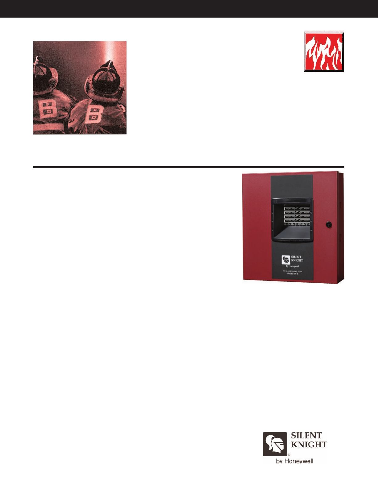
The SK-4 and SK-4E (SK-4/E) are four zone conventional fire alarm
control panels (FACPs) that bring the latest in microprocessor technology
to conventional fire controls. The SK-4 is a 120 VAC FACP and the SK-4E
is a 240 VAC FACP. These FACPs provide reliable fire signaling protection
for small- to medium-sized commercial, industrial, and institutional buildings.
For more information about the SK-4/E system, or to locate your nearest source, please call
1-800-446-6444, or in Minnesota, call 763-493-6435.
FIRE ALARM CONTROL PANEL
Description
The four zone SK-4/E is a 24 VDC
FACP that provides four Class B
initiating device circuits and two Class
B notification appliance circuit (NAC).
The SK-4/E NAC protocol includes the
ability to silence audible devices while
strobes continue to flash, using only a
single pair of wires. The SK-4/E is also
compatible with conventional input
devices such as two- and four-wire
smoke detectors, pull stations,
waterflow devices, tamper switches and
other normally-open contact devices.
Activation of a compatible smoke
detector or any normally-open fire
alarm initiating device activates audible
and visual signaling devices, illuminates
an indicating LED, sounds the piezo
sounder at the F
alarm relay, and operates an
ACP
F
optional module used to notify a remote
station or initiate an auxiliary control
function.
The SK-4/E is compatible with System
®I3
Sensor
advanced features such as drift
compensation, maintenance alert, and
freeze warning.
synchronization of audio/visual devices
is provided, using three selections for
manufacturer protocol.
ACP, activates the
detectors providing
Automatic
Features
• Four Style B (Class B) initiating
device circuits (IDCs)
• Two Style Y (Class B) notification
appliance circuit (NAC)
• Optional module converts all IDCs
and NACs to Class A (PN SK-CAC4)
• Support for synchronization of
standard ANSI audible signals and
ADA compliant strobes per NFPA72
• Selectable for System Sensor,
Wheelock, and Gentex protocols
• Selective silence feature allows
manual silence of horns while strobes
continue to flash on the same NAC
• Program for combination tamper
supervisory monitor and waterflow
alarm on one zone
• Silent or audible walk test operation
mode
• Alarm verification selectable per zone
• Program each zone for supervisory or
fire with separate red and yellow
LEDs
• Disable switches provided per zone
• Program NACS for
– Silence inhibit
– Auto silence
– Strobe synchronization
emporal or steady signal
T
–
– Silenceable or nonsilenceable
– Disable
Form C alarm, trouble, and
•
supervisory relays
• 3A total usable current
6A total usable current with optional
•
second transformer (PN SK-TRM24
or SK-TRM24E)
• Optional dress panel (PN SK-DP2/4)
Electrical Specifications
SK-4 Primary AC: 120 VAC @ 50/60
Hz, 2.3A
SK-4E Primary
1.15A
Wiring: 14 AWG (2.0 mm
insulation min
AC: 240 VAC @ 50 Hz,
2
) with 600 V
SK-4
Initiating Device Circuits (IDCs)
Operating Voltage: 22 VDC nominal;
power-limited
Standby Current: 4 mA
Alarm Current: 15 mA min
Short-circuit Current: 40 mA max
Loop Resistance: 100Ω max
EOL Resistor: 4.7K Ω, 1/2 watt
NACs
Signaling Current: 2.5A
with standard transformer or 5A
total (2.5A
optional transformer
EOL Resistor: 4.7K Ω, 1/2 watt
Form C Relays
ypes: Trouble, alarm, and
T
supervisory
Contact Ratings: 2A @ 30 VAC,
resistive
per NAC) with additional
@ 24 VDC
, power-limited
Page 2

FIRE ALARM CONTROL PANEL
SK-4 & SK-4E
Fire Control Panel
Engineering Specifications
The contractor shall provide a completely electrically supervised fire alarm control panel Silent Knight Model SK-4/E. The system shall contain a fire
alarm control panel capable of operating and supervising smoke detection devices, alarm notification devices, and an on-board annunciator. It shall be
compatible with a digital communicator accessory.
The fire alarm control panel shall have a power limited supply, four Class B initiation circuits which shall accommodate heat detectors, smoke detectors,
and manual pull stations. Smoke detection shall be achieved with either 2- or 4-wire detectors that are compatible with the system. The initiation inputs
hall be programmable as 1) verification zones in which detectors are automatically reset one time before signaling an alarm condition; or 2)
s
combination waterflow supervisory zones that allows the FACPto distinguish between an alarm switch (waterflow device) and a supervisory switch
(tamper) installed on the same circuit. The FACPshall have two 2.5 amp or 5 amp (with an additional optional standard transformer) programmable
notification outputs. It shall have dedicated relays for alarm, trouble, and supervisory. It shall have two power outputs, one resettable and one nonresettable, each rated at 500 mA.
The FACPshall have an on-board annunciator to indicate alarm, supervisory, trouble, and maintenance conditions. The annunciator must include LEDs
for AC, GENERALTROUBLE, ALARM SILENCE, WALK TEST, EARTH FAULT, AND LOW BATTERY. The annunciator shall also contain LEDs to
annunciate fire alarms, troubles, supervisory
for ACKNOWLEDGE, ALARM, SILENCE, RESET, and WALK TEST. The annunciator must also have separate DISABLE switches for each zone and
notification circuit.rr
, and maintenance by zone. The FACPmust be fully operational from the annunciator and include buttons
Electrical Specifications (cont)
Auxiliary Output
Resettable and non-resettable
Operating Voltage: 24 VDC nominal
Current: 500 mA max, power-limited;
total current for nonresettable power,
resettable power and two NACs must
not exceed 6.0A (requires additional
transformer)
Battery
Type: Sealed lead acid only
Charging Circuit: 27.6 VDC @ 0.8A
max normal flat charge
Charging Capacity: 18 AH
Size: 7 AH max allowed in FACP.
Larger batteries can housed
in an RBB accessory cabinet
Compatible Initiating and NAC
Devices
See SK document PN 52612.
Mechanical Specifications
Cabinet Backbox Dimensions:
14.5" W x 15" H x 3" D
(36.83 W x 38.10 H x 7.62 D cm)
Cabinet Door:
14.677" W x 15.342" H x 0.375" D
(37.28 W x 38.97 H x 0.95 D cm)
Cabinet Color: Red
Telephone Requirements:
FCC Part 15 and Part 68 approved
ype of Jack: RJ31X (two required)
T
Installation
The SK-4/E can be surface mounted
using two key slots at the top of the
backbox and two additional 0.25”
diameter holes at the bottom, or semiflush mounted using the optional Trim
Ring P/N TR-1-R
Approvals
NFPA 72; UL Listed;
CSFM 7165-0559: 145;
MEA 297-01-E-3
Ordering Information
SK-4
120 VAC Four Zone Conventional
FACP
SK-4E
AC Four Zone Conventional
240 V
FACP
Accessories
SK-DP2/4
Dress Panel.
panel controls but restricts access to
system wiring.
SK-CAC4
Class AConvertor. Converts Style B
(Class B) IDCs to Style D (Class A) and
Style B (Class B) NACs to Style Z
(Class
Allows access to the
A)
SK-4XTM
Transmitter Module. Provides a
supervised output for local energy
municipal box transmitter and alarm
and trouble reverse polarity.
SK-4XLM
LED Interface Module.
SK-XRM24
110 Volt Transformer 3–6A.
SK-XRM24E
220 Volt Transformer 3–6A.
SK-RZA4
Remote Annunciator.
SK-4XZM
Zone Relay Module.
RBB
Remote Battery Box Accessory
Cabinet. Use if back up batteries are
too large to fit into F
Dimensions: 16”W x 10”H x 6”D
Digital Communicator Accessories
5104B
Six-zone fire control communicator
5129
Four channel slave fire communicator
ACP cabinet.
This document is not intended to be used for installation purposes. W
keep our product information up-to-date and accurate. We cannot cover all
specific applications or anticipate all requirements. All specifications are
subject to change without notice. For more information, contact Silent Knight
7550 Meridian Circle Suite 100, Maple Grove, Mn 55369-4927.
Phone: (800) 328-0103, Fax: (763) 493-6475.
e try to
MADE IN AMERICA
FORM# 350305 Rev
Copyright © 2006 Silent Knight
. C 12/06
 Loading...